1
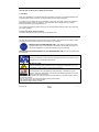
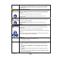
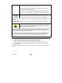
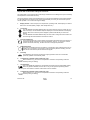
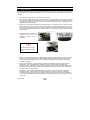
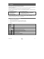
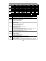
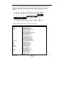
OPERATING INSTRUCTIONS English SUPRA 450/550/750/850/950 – 750Mt°/850Mt°/950Mt° & Nordic version 1. INTRODUCTION This guide has been prepared for the operator of Carrier Transicold refrigeration units. It contains basic instructions for the daily operation of the refrigeration unit as well as safety information, troubleshooting tips, and other information that will help you to deliver the load in the best possible condition. Please take the time to read the information contained in this booklet and refer to it whenever you have a question about the operation of your Carrier Transicold unit. This manual refers to the standard model. Some options may not appear in it, and in such cases you are requested to consult our Technical Services. Your refrigeration unit has been engineered to provide long, trouble-free performance when it is properly operated and maintained. The checks outlined in this guide will help to minimize on the road problems. In addition, a comprehensive maintenance program will help to insure that the unit continues to operate reliably. Such a maintenance program will also help to control operating costs, increase the unit's working life, and improve performance. When having your unit serviced, be sure to specify genuine Carrier Transicold replacement parts for the highest quality and best reliability. At Carrier Transicold, we are continually working to improve the products that we build for our customers. As a result, specifications may change without notice. CONTENTS 1. INTRODUCTION ..........................................................................................................................3 2. IDENTIFICATION .........................................................................................................................5 3. 3.1. WARNINGS AND PRECAUTIONS ..............................................................................................5 Warning stickers maintenance ................................................................................................9 4. PRODUCT LOADING .................................................................................................................10 5. RECOMMENDED TRANSPORT TEMPERATURES .................................................................12 6. 6.1. 7. QUICK GLANCE ON THE DISPLAY BOARD ............................................................................13 Cab control ............................................................................................................................13 OPERATION...............................................................................................................................15 7.1. Pretrip inspection...................................................................................................................15 7.2. Starting the unit – Road operation.........................................................................................16 7.3. Starting the unit – Standby operation ....................................................................................16 7.3.1. Standby operation guidelines ........................................................................................16 7.4. Unit shut down.......................................................................................................................17 7.5. To change setpoint temperature ...........................................................................................17 7.6. Manual defrost.......................................................................................................................17 7.7. To display unit data ...............................................................................................................17 7.8. To change a function.............................................................................................................18 62-61107-02 3 8. OPTIONAL CONTROL PANEL ..................................................................................................19 8.1. Description ............................................................................................................................19 8.2. To operate with auxiliary control panel..................................................................................19 8.2.1. To change the setpoint..................................................................................................20 8.2.2. To set pre-set setpoint...................................................................................................20 8.2.3. To remove pre-set setpoint ...........................................................................................20 8.2.4. To lock and unlock the control panel.............................................................................20 9. 9.1. 9.2. PROBLEMS ................................................................................................................................21 Fuses location .......................................................................................................................21 Fault alarm display and safety features.................................................................................21 10. MAINTENANCE..........................................................................................................................22 Maintenance schedule .....................................................................................................23 10.1. 10.2. Service description...........................................................................................................23 10.3. Recommended oil ............................................................................................................24 11. A.T.P. EUROPE REGULATION EXTRACT ...............................................................................25 12. 24H ASSISTANCE .....................................................................................................................26 62-61107-02 4 2. IDENTIFICATION Keep the fold out sheet while reading the instructions. 1. Nameplate Each unit is identified by a nameplate attached to the frame of the unit. The nameplate identifies the complete model number of the unit, the serial number and some other information. If a problem occurs, please refer to the information on this plate, and make a note of the model and serial number before calling for assistance. This information will be needed when you contact a technician so that he may properly assist you. The complete nameplate is fixed on the frame (1a) and the Serial Number is fixed on the control box (1b): easily readable. 2. Noise level sticker (fixed if available) This sticker indicates the noise level in Lwa (sound power level). 3. WARNINGS AND PRECAUTIONS This manual contains safety and service instructions to follow in order to prevent any accident. Some of following stickers have been placed on the product for your SAFETY. BEFORE USING THIS REFRIGERANT UNIT, read carefully all safety information explained in this manual and indicated on the product. Be sure that everybody who will use this refrigeration unit has been trained to use it in a safe way. DURING THE USE OR MAINTENANCE OF THIS REFRIGERATION UNIT, the notes on safety are to be considered. Personal protective equipment : Always use adequate Personal Protective Equipment before doing anything on this refrigerant unit, as explained in this manual. Working at height : Take all necessary safety precautions when accessing this refrigeration unit : use safe ladders, working platforms with appropriate guards. Automatic start : This refrigeration unit is equipped with Auto-Start/Stop, a valuable fuel saving feature. When this refrigeration unit is set for Auto-start/Stop operation it may start at any time and without warning. Before servicing refrigeration unit, make sure the main power switch is on the OFF position. Ensure the unit will not restart. Lock-out / Tag-out can be performed by disconnecting and enclosing : - The negative battery cable in diesel mode - The electrical plug in electrical mode. 62-61107-02 5 AUTOMATIC START UP IN DIESEL WHEN LOSS OF STANDBY FROM EPROM 3.19 – FOR MONO TEMP FROM EPROM 4.05 – FOR MULTI TEMP NOTE : This option must be configured in service centre according to customer request. To activate this function: TIME STRT set up in functional parameters. When the unit is started in standby, the "ROAD" light is flashing and the "STANDBY" light is lit. After 5 minutes of loss of power, the unit automatically starts in diesel. 5 minutes after the power comes back, the unit starts again automatically in electric mode. The "STANDBY MOTOR" alarm appears, alarm that you would have to clear. * This function will be active even after a stop (OFF) of the unit. To deactivate it: set up TEMP STRT in functional parameters. DEACTIVATE THIS FUNCTION WHEN UNIT IS RUNNING IN A CLOSED AREA ! NOTE : For MONO TEMP – from EPROM 3.23 To be available, this option must be previously configured in Service Center according to customer request. Belts and fans : This refrigeration unit is equipped with Auto-start/stop, it may start at any time and without warning. When the unit is running beware of belts and fans that are moving. Before servicing refrigeration unit, make sure the main power switch is on the OFF position. Ensure the unit will not restart. Lock-out / Tag-out can be performed as described above. When there is protective structure (fan grid or guard for example) make sure they are in place. Never removed them when the refrigeration unit is running. Always keep your hands, body parts, clothes, hairs and tools far from moving parts. 62-61107-02 6 Electricity : When this refrigeration unit is running in electrical operation, some devices are powered up especially in the electrical control box. Before servicing refrigeration unit, make sure the main power switch is on the OFF position. Ensure this refrigeration unit is disconnected from the local electrical network. Lock-out / Tag-out can be performed as described above. Before working in the electrical control box, it is required to control the lack of tension. WHEN IT IS NECESSARY TO WORK IN THE ELECTRICAL CONTROL BOX UNDER TENSION, PEOPLE MUST BE QUALIFIED FOR WORKS UNDER LOW OR HIGH VOLTAGE. Always use adequate tools and Personal Protective Equipment when working on electrical devices : safety gloves and safety glasses. Engine coolant : This refrigeration unit is equipped with a pressurised cooling system. Under normal operating conditions, the coolant in the engine and radiator is under high pressure and very hot. Coolant is very slippery. It can be harmful in case of ingestion. Never remove the cap from a hot radiator when this refrigeration unit is running or immediately after. If the cap must be removed, wait at least 10 minutes and then do so very slowly in order to release the pressure without spray. In case of leakage, immediately clean the floor to prevent slipping. Avoid contact with the skin and eyes. Always use Personal Protective Equipment when handling engine coolant : safety clothes, safety gloves and safety glasses. Refrigerant : The refrigerant contained in this refrigeration unit can cause frostbite, severe burns or blindness in case of projection and direct contact with the skin or eyes. In contact with flame or heat refrigerant generate toxic gas. Refrigerant handling must be done by qualified people. Keep any flame, any lighted object or any source of sparks away from the refrigerant unit. Always use Personal Protective Equipment when handling refrigerant: safety clothes, safety gloves and safety glasses. First aid in case of frost-bite : a. Cover up the frost-bitten part. b. Quickly warm up the frost-bitten part by dipping it into lukewarm water (not hot). If you don't have water, wrap the injured part in a clean cloth. 62-61107-02 7 c. If refrigerant fluid has been splashed into your eyes, rinse them immediately with clean water. As a precaution, you are recommended to have a medical examination as well. Burning with hot and cold : When this refrigeration unit is running or even after, different components can be very cold or hot (exhaust pipe, tubes, coils, receiver, accumulator or engine for example) Beware when operating closed from cold or hot components. Always use adequate safety gloves when doing any maintenance on this refrigeration unit. Cuttings : Beware when handling or operating closed from parts that could be sharp (coils, evaporators, clamps for example). Always use adequate safety gloves when doing any maintenance on this refrigeration unit. Battery : This refrigeration unit may be equipped with a lead-acid type battery. When charging the battery normally vents small amounts of flammable and explosive hydrogen gas. Projections of acids on the skin or eyes can cause severe burns. Keep any flame, any lighted object or any source of sparks away from the battery elements. Always use Personal Protective Equipment when handling and charging battery: safety clothes, safety gloves and safety glasses. Cooling oil : - avoid prolonged or repeated contact with the skin. - wash carefully after handling. "Low pollution" engine : - The TRI-VORTEX-type indirect injection system minimizes exhaust fume pollution. - NEVER START THE ENGINE IN A CLOSED ROOM, EXHAUST GAS IS POISONOUS. - It is colourless and odourless and created by the incomplete combustion of hydrocarbons. - Exhaust gas is poisonous, breathing it in induces drowsiness and may lead to loss of consciousness. 62-61107-02 8 The following symptoms indicate exhaust gas has been inhaled : - Blackout, intense headache, sudden weakness and sleepiness, vomiting, muscular contractions, beating temples. If you feel one of the above mentioned symptoms, go out and breathe fresh air. If you notice a noise or modification of the exhaust system, immediately stop the engine and call your service centre for checking and repair. Environment : Think about protection of environment during all the life of this refrigeration unit. To prevent environmental damages NEVER release refrigerant in the atmosphere, NEVER throw coolant, oil, battery and chemicals in the nature. It must be recuperate and recycle according to current regulations. When disposing this refrigerant unit do it in an environmentally sound way and in accordance with current regulations. CAUTION Under no circumstances should anyone attempt to repair the Logic or Display Boards. Should a problem develop with these components, contact your nearest Carrier Transicold dealer for replacement. Under no circumstances should a technician electrically probe the processor at any point, other than the connector terminals where the harness attaches. Microprocessor components operate at different voltage levels and at extremely low current levels. Improper use of voltmeters, jumper wires, continuity testers, etc. could permanently damage the processor. Most electronic components are susceptible to damage caused by electrical static discharge (ESD). In certain cases, the human body can have enough static electricity to cause resultant damage to the components by touch. This is especially true of the integrated circuits found on the truck/trailer microprocessor. 3.1. Warning stickers maintenance a. Keep the warning pictograms clean and without any obstruction material. b. Clean the pictograms with water and soap and wipe them with soft fabric. c. Replace damaged or missing pictograms with new pictograms available in Carrier network. d. If a component having a pictogram is replaced by a new one, be sure that the new component has the right pictogram. e. Place a warning pictogram by applying it on a dry surface. Press to external sides to eliminate air bubbles. 62-61107-02 9 4. PRODUCT LOADING Proper air circulation in the insulated box, air that can move around and through the load, is a critical element in maintaining product quality during transport. If air cannot circulate completely around the load: hot spots or top-freeze can occur. The use of pallets is highly recommended. Pallets, when loaded so air can flow freely through the pallets to return to the evaporator, help protect the product from heat passing through the floor of the truck. When using pallets, it is important to refrain from stacking extra boxes on the floor at the rear of the truck, because this will cut off the airflow. Product stacking is another important factor in protecting the product. Products that generate heat, fruits and vegetables for example, should be stacked so the air can flow through the product to remove the heat; this is called "air stacking" the product. Products that do not create heat, meats and frozen products, should be stacked tightly in the centre of the box. All products should be kept away from the sidewalls of the body, allowing air to flow between the body and the load; this prevents heat filtering through the walls from affecting the product. It is important to check the temperature of the product being loaded to ensure that it is at the correct temperature for transport. The refrigeration unit is designed to maintain the temperature of the product at the temperature at which it was loaded; it was not designed to cool a warm product. SOME ADVICE Before loading • Pre-cool the inside of the insulated body by lowering the temperature for about 15 minutes. • Evacuate the humidity existing inside the box by carrying out a manual defrost. This can only take place when enabled by the defrost thermostat (box temperature lower than 3°C during pulldown and 8°C during heating). • Evaporator fans are protected by safety grills. In the event of heavy duty use of the unit, ice can accumulate on the grills. It is therefore recommended to clean them regularly by means of a small brush. The operation MUST be done when the unit has been SHUT DOWN. WHEN LOADING • To be carried out with the unit stopped. • It is recommended to open doors as little as possible to avoid the intake of hot air and humidity. • Select the temperature by means of the thermostat, according to the transported goods. • Check the internal temperature of the goods being loaded (using a probe thermometer). • Take care not to obstruct the air intakes on the evaporator section and the ventilation ducts. 62-61107-02 10 • Leave a free space of about : Load spacers Load on pallets - 6 to 8 cm between load and frontwall, - 20 cm between the top of the load and the roof, - between the floor and the load (gratings, pallets). • Do not forget to close the doors. OPTIONS FOR INSULATED BODIES • Mobile partition The mobile partition must be placed at a minimum distance from the evaporator of: - 1300 mm for Supra 450 - 1600 mm for Supra 550 and 750 - 1700 mm for Supra 850 and 950 - 1000 mm from the auxiliary evaporator • Ducting of evaporator air outlet Ventilation ducts must never be covered. • Before closing the doors, check your load once more and see that nobody is shut inside the box. NOTE : For stationary utilization, we recommend to place the body in the shade. IMPORTANT Never leave your unit more than a month without running. 62-61107-02 11 5. RECOMMENDED TRANSPORT TEMPERATURES Below are some general recommendations on product transport temperatures and operating modes for the unit. These are included for reference only and should not be considered pre-emptive of the set-point required by the shipper or receiver. More detailed information can be obtained from your Carrier Transicold dealer. PRODUCT Bananas Fresh fruits vegetables Fresh meats seafood Dairy products Ice Frozen fruits vegetables Frozen meats seafood Ice cream SETPOINT RANGE 15°C 60°F and and and and OPERATING MODE* Continuous +4°C to +6°C +39°F to +43°F Continuous +2°C +36°F Auto-Start/Stop or Continuous +2°C to +6°C -20°C +36°F to +43°F -4°F Auto-Start/Stop or Continuous Auto-Start/Stop -18°C 0°F Auto-Start/Stop -20°C -4°F Auto-Start/Stop -25°C -13°F Auto-Start/Stop * During delivery cycles that include frequent stops and door openings, it is recommended that the unit always be operated in the continuous run mode to help insure product quality. It is essential to shut down the compartment during the periods when the doors are open, in order to maintain the temperature of the cargo in the other compartments and keep the unit operating correctly. It is essential to shut down the compartment during the periods when the doors are open, in order to maintain the temperature of the cargo in the other compartments and keep the unit operating correctly. To do so, the main O/I switch (O:stop/I:start) should be switched to O). 62-61107-02 12 6. QUICK GLANCE ON THE DISPLAY BOARD 6.1. Cab control Keep the fold out sheet while reading the instructions. This refrigeration unit is equipped with a wide range of features that are designed to improve reliability and temperature control within the body. The microprocessor controls incorporated into this unit are the most reliable control system available. It is also designed to be easiest to use, offering great flexibility in control, yet minimal user input for normal operation : a true "set it and forget it" design. 1. Display window : shows set-point, box temperature, operating mode, alarm displays, as well as data on the unit itself (battery voltage, water temperature etc.). 2. Arrows key The UP ARROW and DOWN ARROW keys are used to alter the set-point. Press the up or down arrow keys until the desired setpoint is displayed on the left-hand side of the display window. When the correct set-point is displayed, press the ENTER key to confirm the setting. The UP ARROW and DOWN ARROW keys are also used to change the unit functions and scroll through the FUNCTION and UNIT DATA screens. 3. Function Change key The function change key is used to display the operating parameters. Each time this key is pressed the display will advance to the next parameter. This key, in conjunction with the up/down arrow and enter keys, will allow the user to change the parameters. 4. RUN/STOP switch The main unit RUN/STOP switch controls the unit operation. When switched to the Run (I) position, the unit will start in the operating mode last entered (Road or Standby). The setpoint will be at the last set-point entered on the keypad. 5. Road key The ROAD key puts the unit into Road (or engine) operation when the unit has been previously operated in the Standby mode. 6. Compartment 1 ON/OFF switch (multi temp only) When switched on (I), the unit and compartment 1 will start in the operating mode last entered (cooling or heating). 7. City Speed key The CITY SPEED key toggles the unit between high speed and low speed (diesel mode). When City Speed is selected, the unit will run only in low speed except during defrost cycles. This feature is useful in areas where noise is restricted. 8. Compartment 2 ON/OFF switch (multi temp only) When switched on (I), the unit and compartment 2 will start in the operating mode last entered (cooling or heating). 62-61107-02 13 9. Manual defrost key The MANUAL DEFROST key places the unit in a defrost cycle. Under most conditions it is not necessary to defrost the unit manually as this is done automatically with the air switch or the defrost timer. Manual defrost may become necessary due to ice accumulated on the evaporator coil during frequent door openings in humid environments. 10. Compartment 3 ON/OFF switch (multi temp only) When switched on (I), the unit and compartment 3 will start in the operating mode last entered (cooling or heating). 11. Buzzer Off key The BUZZER OFF key temporarily turns off the FAULT ALARM buzzer. The red light "Fault alarm" remains illuminated on the command cab. 12. Standby key The STANDBY key places the unit in Standby (or electric) mode when the previous mode of operation has been Road. 13. Pretrip Check key The PRETRIP key initiates a check of all normal operating modes. The temperature inside the box must be below 5°C ± 1°C (35°F ± 2°F) to start this check. Upon initiation, the unit will cycle through all operating modes at 30 second intervals. The display will show "PPPP" at the beginning and will show various unit data during the pre-trip cycle. Upon completion of the pre-trip cycle the unit will be placed into the defrost mode. 14. Auto Start/Stop Continuous key The AUTO-START/STOP key toggles the unit operating mode between Auto-Start/Stop and continuous run. When the unit is set for Auto-Start/Stop operation, the unit will run until the box temperature reaches set-point and then cycle off (after the minimum run time has been met) until further cooling or heating is necessary. When in the continuous mode, the unit will cycle between heat and cool as required to maintain the set temperature in the body. If the setpoint is below –12°C (10°F) the unit will not heat, it will run continuously in low speed cool. 15. Unit Data key This key scrolls the display through the various operating condition displays, engine temperature or battery voltage, for example. A more complete description of the function is found later in this chapter. 16. Fault Alarm led : illuminates when an alarm is detected. 17. Enter key The ENTER key confirms changes made to unit operation. It must be pressed to change the setpoint after using the arrow keys to adjust it. If the ENTER key is not pressed, the setpoint will revert to the previously entered setting. The ENTER key must also be pressed whenever a FUNCTION setting is being altered. If this key is not pressed, the function will revert to its previous setting. 62-61107-02 14 7. OPERATION 7.1. Pretrip inspection The pre-trip inspection should be performed before picking up any load. This inspection is essential to anticipate and help minimize the possibility of "over-the-road" problems. These checks take only a few minutes. 1. Place the unit's main switch (4.) in the STOP (O) position. 2. Fuel - drain any water and impurities from the sump of the refrigeration unit fuel tank by opening the drain-cock located on the bottom of the tank (if so equipped). Close the valve when only pure fuel emerges. Check the fuel level in the tank, ensuring that the fuel supply is adequate for unit operation. Refuel if necessary. 3. Engine Oil - the engine oil should be checked last since it is necessary for oil to drain out of the block and into the oil pan to obtain a correct reading. Remove the plug/dip-stick, wipe it off and reinsert it fully into the engine block. Once again, remove the dip-stick and observe the oil level; it should be somewhere between the full and add marks. If it is below the add mark, add oil until the level is correct. 4. Check coolant level through the openings of the front grill: complete coolant level if necessary. DO NOT remove the cap from a hot radiator : burns risks. 5. Battery - on unit equipped with serviceable batteries, the level of the electrolyte in each of the cells should be checked. If the level is low, distilled water should be added to the correct level. Most units, however, are equipped with low or no-maintenance batteries. Check battery connections and battery supports. 6. Over-all Unit inspection - visually inspect the entire unit for leaks, loose bolts, frayed, loose, or broken wires, etc. The radiator and condenser coils of the unit should be free of dirt, bugs, cardboard, or any other debris that may obstruct airflow across the coils. The evaporator (located inside the body) should be free of debris also, especially shrink-wrap, which is often used during transport to prevent cargo shifting. 7. Truck body - The body should be inspected prior to loading. Check the door and vent seals for damage and wear. Inspect the entire interior and exterior of the body to detect any damage including in the inner and outer skins of the body. Damage to the insulation may compromise the unit's ability to maintain the product temperature by increasing the amount of heat gain across the truck body. 62-61107-02 15 7.2. Starting the unit – Road operation 1. Complete the PRETRIP inspection described in the previous section. 2. Place the RUN/STOP switch (O/I) (4.) to the RUN position (I) 3. Press the ROAD operation key (5.) (only if the unit has been previously used in standby mode). 4. Place either one or two compartments OFF/ON switches (6. or 8.) to ON (I) - For Mt° only 5. Then, the unit will : - perform a complete diagnostic check on the microprocessor controller - pre-heat for the required amount of time based on the engine temperature - starts automatically 7.3. Starting the unit – Standby operation 1. Check that the unit is connected to a suitable electricity supply. (see section 7.3.1). 2. Place the RUN/STOP switch (4.) (O/I) to the RUN position (I) 3. Press the STANDBY operation key (12.). 4. Place either one or two compartments OFF/ON switches (6. or 8.) to ON (I) - For Mt° only 5. Then, the unit will begin to run on electric power. 7.3.1. Standby operation guidelines For safe, reliable operation in Standby mode, it is important to consider the following guidelines : a. NEVER plug the unit in to the power source with the main switch in the RUN position. The main switch should always be in the STOP position when connecting the unit to the power source. b. The fusing and extension cable used for Standby operation should conform to the following: Unit Supra 450 Supra 550 Supra 750 Supra 750Mt° Supra 850 Supra 850Mt° Supra 950 Supra 950Mt° Fuse 200/240/3/50Hz 220/256/3/60Hz 16 A 16 A 23 A 50 A 40 A Fuse 350/415/3/50Hz 380/460/3/60Hz 10 A Standardized extension cable H.07.RNF 230 volts 400 volts 4 x 4 mm 2 13 A 30 A 29 A 4 x 2.5 mm 4 x 6 mm 4 x 10 mm 2 2 4 x 6 mm 2 2 4 x 6 mm 2 c. The unit connection cable must be fitted with a ground connection. The cable must be connected to earth. d. On standby mode, the unit MUST BE CONNECTED to a high sensibility (30mA) differential protection. 62-61107-02 16 e. When performing service and/or maintenance procedures on a refrigeration unit, make certain that the unit is disconnected from the power source and that the main unit switch is turned OFF. f. Operations on the 400 V supply for the unit must only be carried out by authorized personnel. g. The user is liable for ensuring that the above measures are taken. Warning : changing the operation of a unit from 400 V to 220 V implies a change in the electrical coupling, adjustment of the overload relay and for certain unit models, the replacement of some components. Please consult our technical service. 7.4. Unit shut down 1. Place C1, C2 or C3 switches (6., 8. or 10.) to the OFF position (O) – For Mt° only. 2. Place the RUN/STOP switch (4.) (O/I) to the OFF (O) position. To shut down the unit, ALWAYS use the cab command. 7.5. To change setpoint temperature The sequence is the same for each compartment. 1. 2. 3. Start the unit by placing the RUN/STOP switch (4.) to the RUN position (I). When the setpoint box temperature is displayed, press the UP or DOWN ARROW key (2.) to change the temperature setpoint. Press the ENTER key (17.) to validate. 7.6. Manual defrost 1. Press the MANUAL DEFROST key (9.). If conditions are required, a defrost cycle will be initiated. 7.7. To display unit data The unit data list can be scrolled through by pressing the UNIT DATA key (15.). The list will advance by one with each key press; or, press the UNIT DATA key once and use the UP or DOWN ARROW (2.) keys to scroll through the list more quickly. Press the ENTER key (17.) to display the data for 30 seconds. UNIT DATA CODE CD1 CD2 CD3 CD4 CD5 CD6 CD7 CD8 CD9 62-61107-02 ENGLISH SUCT ENG WT RAS *SAS *REM ATS EVP CDT DATA Suction pressure Engine hours Engine temperature Return air temperature Supply air temperature Remote air temperature Ambient temperature Evaporator temperature Compressor discharge temperature 17 CD10 BATT Battery voltage CD11 SBY Standby (electric motor) hours CD12 MOD V Future expansion CD13 REV Software revision CD14 SERL Serial number low CD15 SERU Serial number upper CD16 2RA Compartment 2 – return air temperature CD17 3RA Compartment 3 – return air temperature CD18 MHR1 Maintenance hour meter 1 CD19 MHR2 Maintenance hour meter 2 CD20 SON Switch on hour meter *SAS and REM are options. SAS is displayed when the SUP PROBE function is selected. REM is displayed when the REM PROBE function is selected. 7.8. To change a function 1. 2. 3. 4. Press the FUNCTION CHANGE key (3.) until the function you want to change appears on the display. Press the ENTER key (17.). Press the UP or DOWN ARROW key (2.) until the function setting you want appears on the display. Press the ENTER key (17.) to validate new setting. CODE ENGLISH FN0 DEFR FN1 ON CITY SPEED FN1 OFF HIGH SPEED FN2 OFF T FN3 ON T FN4A REM PROBE FN4B SUP PROBE FN5 F/C DEGREES F/C FN6 ON TIME STRT FN6 OFF TEMP STRT FN7 0 MOP SDT FN7 -5 MOP FN7 +4 MOP + FN10 ON AUTO OP FN10 OFF MAN OP FN11 T RANGE CODES / ENGLISH NORM / ADD GLOW FUNCTION PARAMETERS AVAILABLE SELECTIONS Defrost interval 1.5, 3, 6 or 12hr Low speed only Low and high speed Minimum Off-time 10, 20, 30, 45 or 90mn On-time 4 or 7 mn Controlling probe Standard unit selected (default C) Maximum Off time Mop selection Start mode Out of range (A=2°C / B=3°C / C=4°C) Code or english display format Manual glow override. Normal of add 30 seconds Alarm RST = Alarm reset required ALARM RST / CLR Alarm CLR = No alarm active Selection in bold are factory settings. 62-61107-02 18 8. OPTIONAL CONTROL PANEL 8.1. Description Keep the fold out sheet while reading the instructions. User-friendly indicator and operator control panels clearly show individual compartment temperatures with easy-to-read displays. These compact panels can be mounted to suit the individual operator's preferences. (Example : on the front bulkhead, in the cab or in the refrigerated compartment - including mounting in the truck wall itself) 18. 19. 20. 21. 22. Compartment on/OFF key Control panel power on Unit ON/OFF key Manual defrost key Control panel locking 23. 24. 25. 26. Up and down arrow keys Heating operating mode light of a compartment Cooling operating mode light of a compartment Temperature indicated in °C or °F From this optional control panel, you can : switch on the unit, check compartment 1, 2 or 3 temperatures, change setpoints, energize a manual defrost. 8.2. To operate with auxiliary control panel 1. Start the unit as mentioned before. 2. Press the SYSTEM ON/OFF key (20.). Power light will go ON. 3. Press the ON/OFF key (18.) to energize selected compartment. 4. Display waiting for communication with unit compartment temperature display setpoint temperature display evaporator status (heat or cool or null) compartment shut-down via remote control defrost compartment temperature sensor malfunction 62-61107-02 19 8.2.1. To change the setpoint Setpoint change can be made from control panel or cab control. 1. Press the UP or DOWN ARROW key (23.) to increase or decrease setpoint. This is the same operation for each compartment. 8.2.2. To set pre-set setpoint The control panel allows the user to pre-set 5 different temperatures on each compartment. 1. Switch main RUN/STOP switch (4.) and required remote compartment switches (18.) on the unit to RUN. 2. Press Carrier logo and the lock light will be displayed. 3. Press host compartment UP ARROW key for 10 seconds. P1 will be displayed in all compartments. 4. Set lowest setpoint temperature required. 5. Press Carrier logo and P2 will be displayed. Set next lowest temperature required up to five preset setpoints are available. 6. Pressing the second compartment up or down arrow will allow the lowest temperature required to be preset in the second compartment. Pressing Carrier logo will then move on to the nest lowest (up to five). 7. Press the Carrier logo for 10 seconds and this will remove the lock light and store the pre-set setpoints in memory. 8.2.3. 1. To remove pre-set setpoint Switch main RUN/STOP switch and required remote compartment switches on the unit to RUN. 2. Press Carrier logo and the lock light will be displayed. 3. Press host compartment up arrow for 10 seconds. P1 will be displayed in all compartments. 4. Set temperature to lowest possible and OFF will be displayed. 5. Press the UP ARROW key on remote compartments will display the presets, take the temperature to the lowest possible and OFF will be displayed. 6. Press the Carrier logo for 10 seconds and the new information will be stored in memory. 8.2.4. To lock and unlock the control panel 1. Press the CARRIER logo 10 seconds to lock the control panel. 2. then, starts to flash in the new logic. 3. Press again the CARRIER logo 10 seconds to unlock. 4. The indicator goes off. NOTE It is not necessary for the compartment to be running in order to modify or see the setpoint value and the temperature of the compartment. The unit can be shut down both with the control panel and the general switch. 62-61107-02 20 9. PROBLEMS Everything possible has been done to ensure that your unit is the most reliable, trouble-free equipment available on the market today. If, however, you run into problems, the following section may be of assistance. If you do not find the trouble that you have experienced listed below, please call your Carrier Transicold dealer for assistance. Unit won't crank, by the starter Unit won't start Unit won't run Unit dies Unit not cooling properly General problems Check battery condition Check battery connection Check all fuses Check fuel level Check all fuses Check fuel level Check engine oil level Check all fuses Check belts Check engine oil level Check coolant level Check fuel level Check all fuses Defrost unit Check evaporator for airflow restriction Check condenser for airflow restriction Check body for damage or air leaks 9.1. Fuses location Refer to the electrical schematic provided with the unit. If a fuse has blown, AL15 FUSE BAD will be displayed. Please contact your Carrier Service Center. 9.2. Fault alarm display and safety features Display will alternate between an alarm message and the normal display whenever any of the failures listed below occur. NOTE : Whenever the fault light is on, check display for fault message. 1. - Reset the micro to start the unit by moving the RUN/STOP switch (4.) to STOP (O) then to RUN (I). 2. - Press FUNCTION CHANGE key (3.). 3. - Press the UP/DOWN ARROW keys (2.) until ALARM RST is displayed. 4. - Press the ENTER key (17.) to clear alarm. Alarm CLR will now be displayed and unit will restart. 62-61107-02 21 Other method to reset : move RUN/STOP switch (4.) to STOP. Unit resets and will start when RUN/STOP switch is moved to run position. ALARM DISPLAY √ = FAULT LIGHT ON CODE ENGLISH DESCRIPTION AL0 ENG OIL √ Low oil pressure AL1 ENG HOT √ High coolant temperature AL2 HI PRESS √ High pressure AL3 STARTFAIL √ Start failure AL4 LOW BATT √ Low battery voltage AL5 HI BATT √ High battery voltage AL6 DEFRFAIL Defrost override AL7 ALT AUX (√) Alternator auxiliary AL8 STARTER √ Starter motor AL9 RA SENSOR √ Return air sensor AL10 SA SENSOR Supply air sensor AL11 WT SENSOR Coolant temperature sensor AL12 HIGH CDT √ High discharge temperature AL13 CD SENSOR Discharge temperature sensor AL14 SBY MOTOR √ Standby motor overload AL15 FUSE BAD √ Fuse open AL16 SYSTEM CK System check AL17 DISPLAY Display AL18 SERVICE1 Maintenance hour meter 1 AL19 SERVICE2 Maintenance hour meter 2 AL20 RAS OUT √ Main compartment out-of-range AL21 2RA OUT √ Remote compartment 2 out-of-range AL22 3RA OUT √ Remote compartment 3 out-of-range AL23 NO POWER No power for standby √ = FAULT LIGHT ON WARNING : AL0 (ENG OIL) could come up if alternator is badly connected. 10. MAINTENANCE A comprehensive maintenance program will help to insure that the unit continues to operate reliably. Such a maintenance program will also help to control operating costs, increase the unit's working life, and improve performance. NOTE All maintenance services must be done by a technician trained on Carrier products respecting all safety and quality standards of Carrier. 62-61107-02 22 10.1. Maintenance schedule Unit Supra 450 500 Supra 750&Mt 850&Mt Supra 950&Mt HOURS Initial service Service A Service B Service C HOURS Initial service Service A Service B Service C HOURS Initial service Service A Service B Service C 250 500 1000 1500 2000 2500 3000 3500 4000 4500 5000 5500 6000 6500 7000 7500 8000 8500 1500 2250 3000 3750 5250 6000 6750 7500 8250 9000 750 4500 2000 3000 5000 6000 7000 8000 1000 4000 250 9750 10500 11250 12000 12750 13500 250 9000 10000 11000 12000 13000 14000 15000 16000 17000 18000 10.2. Service description Initial service Service A Service B Service C • Check the tightness of bolts and screws and that the unit is correctly fastened onto the box • Drain the engine oil, replace oil filter and by-pass filter (if so equipped) • Drain the engine oil, replace oil filter and by-pass filter (if so equipped) • Clean up the cartridge of the dry air filter • Clean up battery & battery clamps • Check engine cooling system • Adjust all the belts • Operations of service A + • Replace fuel filter • Replace the cartridge of the dry air filter • Clean up fuel pump filter • Clean up condenser and radiator coil • Clean up mechanical clutch • Check the battery terminals and fluid levels • Check compressor oil level • Check alternator brushes • Check engine thermostat for proper operation • Check defrost (check timer setting and function, check refrigerant control valves, fans stop, defrost ends automatically, water drains from evaporator) • Check fan motor brushes and replace if necessary • Check and adjust rocker arms • Operations of service B + • Replace alternator brushes • Replace all the belts • Check refrigerant level • Check engine speed under load • Clean and adjust fuel injectors Filter Drier, Compressor oil & Refrigerant change EVERY TWO YEARS 62-61107-02 • • • • 9000 Replace filter drier Clean up the expansion valve Replace compressor oil - only use Ester oil (POE) approved by Carrier Transicold Replace refrigerant 23 10.3. Recommended oil Engine oil : the oils recommended for use in your refrigeration unit must comply with the American Petroleum Institute's (API) SG/CD rating. The use of oil of the proper weight (viscosity) is also essential. The following chart indicates the SAE Weight Rating of the oil to be used in various climates: 20W or 15W40 20W or 15W40 10W or 10W30 The following oils are accepted for use in Europe with these units. RECOMMENDED OILS CARRIER CARRIER TD+15W-40 AGIP ANTAR BP SIGMA TURBO SHPD 15W-40 GRAPHITE R 15W-40 VANELLUS C3 EXTRA 15W-40 VANELLUS FE 15W30 MULTIPERFORMANCE4D 15W-40 PERFORMANCE TROPHY 15W-40 URANIA TURBO 15W-40 KAPPA LDO 15W-40 KAPPA TD PLUS 15W-40 KAPPA EXTRA 15W-40 DETERGENTE 4DM 15W-40 STRADEX 900 ECO 15W-40 SYNTHIDEX ECO 15W-40 RALLYE TURBO 4E 15W-40 RALLYE TURBO 4E LD 15W-40 RAFF SUPER HPDO 15W-40 MEGAMAXI 15W-40 DELVAC SHC 15W-40 DELVAC 1400 SUPER OPALGET D 500 15W-40 TURBO 2002 15W-40 POLATRUCK 15W-40 KMX 2 PLUS 15W-30 KMX 2 PLUS 15W-40 MV5 EUROPE " URSA SUPER TD 15W-40 RUBIA TIR MAX 15w40 MYRINA TX 15W-40 MYRINA T 15W-30 SUPER ROC 3D 15W-40 TURBO DX 15W-40 SM 4D + 15W-40 ELF FIAT FINA HAFA IGOL IMPERATOR LABO MOBIL OPAL ORLY POLAROIL RENAULT TEXACO TOTAL SHELL UNIL YACCO 62-61107-02 24 11. A.T.P. EUROPE REGULATION EXTRACT Approval of vehicles intended for the carriage of perishable goods. Before putting a refrigerated vehicle into service, it is necessary to have it approved by the Regional Health Department. Characteristics of vehicles used for carrying perishable goods; refrigeration unit. The refrigeration unit is an insulated unit with a cooling system which makes it possible, with a mean outside temperature of +30°C, to lower the temperature inside the empty body and to maintain this low temperature in the following way: class A : Refrigeration unit furnished with a cooling system whereby a temperature between +12°C and 0°C inclusive can be chosen. class B : Refrigeration unit furnished with a cooling system whereby a temperature between +12°C and –10°C inclusive can be chosen. class C : Refrigeration unit furnished with a cooling system whereby a temperature between +12°C and –20°C inclusive can be chosen. The cooling capacity of a unit is determined by a test carried out in one of the approved testing stations and ratified by an official report. Note: The "K" factor of bodies intended to be classified as C must be equal to or lower than 0.4 W/m2 °C. Signs, identification marks and plates to be attached to refrigeration units Refrigeration Plate This reference must be followed by identification marks according to the following list: Standard refrigeration unit Class A FNA Reinforced refrigeration unit Class A FRA Reinforced refrigeration unit Class B FRB Reinforced refrigeration unit Class C FRC In addition to the above identification marks, the date (month and year) of expiry of the approval certificate must be indicated. Example: FRC 6-2004 (6 = month (June) 2004 = year) Very important Regularly check the expiry date of the approval certificate. During transport, the approval certificate or provisional certificate should be shown on request of qualified agents. To have an insulated unit approved as a refrigeration unit, an application to modify the approval certificate should be sent to the regional health office. 62-61107-02 25 12. 24H ASSISTANCE At Carrier Transicold we're working hard to give you complete service when and where you need it. That implies a worldwide network of dealers and available an emergency service. These service centres are manned by factory-trained service personnel and backed by extensive parts inventories that will assure you of prompt repair. Should you encounter a unit problem with your refrigeration unit during transit, follow your company's emergency procedure or contact the nearest Carrier Transicold service centre. Consult the directory to locate the service centre nearest you. This directory may be obtained from your Carrier Transicold dealer. If you are unable to reach a service center, call Carrier Transicold’s 24Hour Assistance: In Europe, please use the following free phone numbers from : A B CH D DK E F FIN GB GR H I IRL L RUS N NL P PL S AUSTRIA BELGIUM SWITZERLAND GERMANY DENMARK SPAIN FRANCE FINLAND GREAT BRITAIN GREECE HUNGARY ITALY IRELAND LUXEMBURG RUSSIA NORWAY THE NETHERLANDS PORTUGAL POLAND SWEDEN 0800 291039 0800 99310 0800 838839 0800 1808180 808 81832 99 993213 0800 913148 0800 113221 0800 9179067 00800 3222523 06800 13526 800 791033 1800 553286 800 3581 810 800 200 31032 800 11435 0800 0224894 8008 32283 00800 3211238 020 790470 From other countries / Direct : +32 9 255 67 89 In Canada or United States, call 1 – 800 – 448 1661 When calling, please have the following information ready for fastest service : • • • • • Your name, the name of your company, and your location A telephone number where you can be called back Refrigeration unit model and serial number Box temperature, setpoint and product Brief description for the problem you are having and what you have already done to correct the problem. We will do everything we can to get your problem taken care of and get you back on the road. 62-61107-02 26