1
'&OPERATING
INSTRUCTIONS
INDEX
1
OPENING AND CHECKING THE PACKAGE....................................................................................... 5
1.1
1.2
1.3
1.4
2
Contents of the package ................................................................................................................ 5
Opening the package ..................................................................................................................... 5
Checking the markings................................................................................................................... 5
Marking Data ................................................................................................................................. 5
DESCRIPTION ..................................................................................................................................... 6
2.1
Specifications................................................................................................................................. 6
2.1.1
2.1.2
2.1.3
2.2
Equipment that can be connected to the DCJ keyboard.................................................................. 6
2.2.1
2.2.2
2.2.3
2.3
2.4
2.5
3
Keys and connectors...................................................................................................................... 7
Second function keys ..................................................................................................................... 8
Dip switch ...................................................................................................................................... 8
Video and telemetry lines ............................................................................................................... 9
RS485 and system types ............................................................................................................... 9
Standard connection cable........................................................................................................... 10
One control keyboard per line ...................................................................................................... 11
More than two devices on the same line....................................................................................... 11
KEYBOARD SETUP .......................................................................................................................... 12
4.1
4.2
4.3
4.4
Keys ............................................................................................................................................ 12
Selecting and inserting values...................................................................................................... 12
Menu items .................................................................................................................................. 12
Assigning the telemetry lines........................................................................................................ 15
4.4.1
4.4.2
4.4.3
4.5
4.6
Default setting............................................................................................................................................18
Modifying the list ........................................................................................................................................18
Accepting the request for multiplexers.......................................................................................... 18
4.7.1
4.7.2
4.8
4.9
4.10
4.11
4.12
4.13
Default setting............................................................................................................................................16
Modifying the list ........................................................................................................................................16
Warning message ......................................................................................................................................17
Accepting the request for monitors ............................................................................................... 18
4.6.1
4.6.2
4.7
Default setting............................................................................................................................................15
Assigning all receivers to a single line .......................................................................................................15
Modifying the list ........................................................................................................................................15
Accepting requests for cameras ................................................................................................... 16
4.5.1
4.5.2
4.5.3
Default setting............................................................................................................................................18
Modifying the list ........................................................................................................................................18
Accepting requests for functions................................................................................................... 18
Joystick calibration and test.......................................................................................................... 19
Buzzer ......................................................................................................................................... 20
Password..................................................................................................................................... 20
Warning and error messages ....................................................................................................... 20
Autotest of serial channels ........................................................................................................... 21
4.13.1
5
Video matrix.................................................................................................................................................6
Video multiplexer .........................................................................................................................................7
Telemetry receivers and domes...................................................................................................................7
COMMUNICATION LINES AND CONNECTIONS ................................................................................ 9
3.1
3.2
3.3
3.4
3.5
4
Keyboard .....................................................................................................................................................6
Set up ..........................................................................................................................................................6
Security........................................................................................................................................................6
Autotest procedure.....................................................................................................................................21
VIDEO MANAGEMENT...................................................................................................................... 22
5.1
5.2
Description of the display ............................................................................................................. 22
Video: fundamental concepts ....................................................................................................... 22
Pag. 1
DCJ 4302
5.2.1
5.2.2
5.2.3
5.2.4
5.3
Video matrix SM84A and SM164A ............................................................................................... 26
5.3.1
5.3.2
5.3.3
5.4
Description.................................................................................................................................................40
Connexion..................................................................................................................................................40
Dedicated functions ...................................................................................................................................41
Controlling the multiplexer using a video device ........................................................................... 41
5.11.1
5.11.2
6
Description.................................................................................................................................................38
Direct connection .......................................................................................................................................38
Dedicated functions ...................................................................................................................................39
Video multiplexer SP16C ............................................................................................................. 40
5.10.1
5.10.2
5.10.3
5.11
Description.................................................................................................................................................35
Connection.................................................................................................................................................35
Matrix setup ...............................................................................................................................................36
Video multiplexer Javelin/Hitron ................................................................................................... 38
5.9.1
5.9.2
5.9.3
5.10
Description.................................................................................................................................................34
Connection.................................................................................................................................................34
Matrix setup ...............................................................................................................................................34
Video matrix SW164OSM ............................................................................................................ 35
5.8.1
5.8.2
5.8.3
5.9
Description.................................................................................................................................................32
Connection.................................................................................................................................................32
Operational test .........................................................................................................................................32
Video device setup.....................................................................................................................................33
Video matrix SW328 .................................................................................................................... 34
5.7.1
5.7.2
5.7.3
5.8
Description.................................................................................................................................................30
Connection.................................................................................................................................................30
Video device setup.....................................................................................................................................31
Switchers Linxs LXRPS42A and LXRPS82A ................................................................................ 32
5.6.1
5.6.2
5.6.3
5.6.4
5.7
Description.................................................................................................................................................28
Connection.................................................................................................................................................28
Video device setup.....................................................................................................................................29
Video matrix Linxs LXRPS84A and LXRPS164A.......................................................................... 30
5.5.1
5.5.2
5.5.3
5.6
Description.................................................................................................................................................26
Connexion..................................................................................................................................................26
Video device setup.....................................................................................................................................27
Switchers SM42A and SM82A ..................................................................................................... 28
5.4.1
5.4.2
5.4.3
5.5
Direct selection of a camera ......................................................................................................................23
Selecting the previous/next camera ...........................................................................................................23
“Views”.......................................................................................................................................................23
Receivers associated with the cameras.....................................................................................................24
Selecting a monitor connected to the video matrix.....................................................................................41
Selecting a monitor connected to the multiplexer ......................................................................................42
TELEMETRY CONTROL.................................................................................................................... 43
6.1
6.2
Controlling the telemetry directly and using video systems ........................................................... 43
Common telemetry operations ..................................................................................................... 44
6.2.1
6.3
6.4
6.4.1
6.4.2
6.5
Special codes ............................................................................................................................................45
Typographical conventions ........................................................................................................................45
Elmo dome .................................................................................................................................. 46
6.5.1
6.5.2
6.5.3
6.5.4
6.5.5
6.5.6
6.5.7
6.6
Changing the active receiver .....................................................................................................................44
Communication problems between keyboard and receiver ........................................................... 44
Notes regarding telemetry control................................................................................................. 45
Reference material and documents ...........................................................................................................46
Connection.................................................................................................................................................46
Setup .........................................................................................................................................................46
Autopan .....................................................................................................................................................47
Preset, scan, home ....................................................................................................................................48
Sequences and Cruise...............................................................................................................................48
Other functions ..........................................................................................................................................48
Ernitec Saturn Dome.................................................................................................................... 49
6.6.1
6.6.2
6.6.3
Reference material and documents ...........................................................................................................49
Connection.................................................................................................................................................49
Setup .........................................................................................................................................................49
Pag. 2
DCJ 4302
6.6.4
6.6.5
6.6.6
6.6.7
6.6.8
6.6.9
6.7
JVC Dome ................................................................................................................................... 52
1.1.1
6.7.2
6.7.3
6.7.4
6.7.5
6.7.6
6.7.7
6.8
Reference material and documents ...........................................................................................................63
Connection.................................................................................................................................................63
Setup .........................................................................................................................................................63
Autopan .....................................................................................................................................................64
Preset, scan, home, patrol .........................................................................................................................64
Pattern .......................................................................................................................................................64
Other functions ..........................................................................................................................................65
Sensormatic / American Dynamics dome ..................................................................................... 66
6.11.1
6.11.2
6.11.3
6.11.4
6.11.5
6.11.6
6.11.7
6.12
Reference material and documents ...........................................................................................................60
Connection.................................................................................................................................................60
Setup .........................................................................................................................................................60
Preset, scan, home ....................................................................................................................................60
Pattern .......................................................................................................................................................61
Zone...........................................................................................................................................................61
Lenses .......................................................................................................................................................61
Relays and alarms .....................................................................................................................................61
Other functions ..........................................................................................................................................62
Samsung Dome ........................................................................................................................... 63
6.10.1
6.10.2
6.10.3
6.10.4
6.10.5
6.10.6
6.10.7
6.11
Reference material and documents ...........................................................................................................55
Important protocol note ..............................................................................................................................55
Connection.................................................................................................................................................55
Setup .........................................................................................................................................................56
Autopan .....................................................................................................................................................56
Autopan functions for WV-CS850 model ...................................................................................................57
Limit movement for WV-CS850 model.......................................................................................................57
Preset, scan, home ....................................................................................................................................57
Patrol Setup for the WV-CS850 model ......................................................................................................57
Patrol setup for WV-CS600 model .............................................................................................................57
Shutter and Electronic sensitivity setup .....................................................................................................57
Autoflip.......................................................................................................................................................58
Lenses and flip...........................................................................................................................................58
Relè (only WV-CS850 model)....................................................................................................................59
Other functions (only WV-CS850 mode)....................................................................................................59
Pelco dome.................................................................................................................................. 60
6.9.1
6.9.2
6.9.3
6.9.4
6.9.5
6.9.6
6.9.7
6.9.8
6.9.9
6.10
Reference material and documents ...........................................................................................................52
Connection.................................................................................................................................................52
Setup .........................................................................................................................................................52
Autopan .....................................................................................................................................................53
Preset, home, scan ....................................................................................................................................53
Patrol .........................................................................................................................................................54
Other commands and special codes..........................................................................................................54
Panasonic dome .......................................................................................................................... 55
6.8.1
6.8.2
6.8.3
6.8.4
6.8.5
6.8.6
6.8.7
6.8.8
6.8.9
6.8.10
6.8.11
6.8.12
6.8.13
6.8.14
6.8.15
6.9
Autopan .....................................................................................................................................................50
Preset, scan, patrol and home ...................................................................................................................50
Auxiliary relays...........................................................................................................................................51
Lenses .......................................................................................................................................................51
Return position...........................................................................................................................................51
Other special codes ...................................................................................................................................51
Reference material and documents ...........................................................................................................66
Connection.................................................................................................................................................66
Setup .........................................................................................................................................................66
Preset, scan, home ....................................................................................................................................67
Pattern and “apple peel” ............................................................................................................................67
Relays........................................................................................................................................................67
Other functions ..........................................................................................................................................68
Star Dome ................................................................................................................................... 69
6.12.1
6.12.2
6.12.3
6.12.4
6.12.5
6.12.6
Reference material and documents ...........................................................................................................69
Connection.................................................................................................................................................69
Preset, scan, home ....................................................................................................................................69
Autopan, patrol, tour ..................................................................................................................................69
Setup .........................................................................................................................................................72
Other functions ..........................................................................................................................................73
Pag. 3
DCJ 4302
6.13
VCL Dome ................................................................................................................................... 74
6.13.1
6.13.2
6.13.3
6.13.4
6.13.5
6.13.6
6.13.7
6.14
6.15
Videotec and Linxs receivers........................................................................................................ 77
Videotec and Linxs receivers with Videotec protocol..................................................................... 78
6.15.1
6.15.2
6.15.3
6.15.4
6.15.5
6.15.6
6.15.7
6.16
Reference material and documents ...........................................................................................................74
Connection.................................................................................................................................................74
Preset, scan, home ....................................................................................................................................74
Autopan and tour .......................................................................................................................................74
Camera setup ............................................................................................................................................75
Lenses .......................................................................................................................................................76
Other functions ..........................................................................................................................................76
Reference material.....................................................................................................................................78
Connexion..................................................................................................................................................78
Preset, scan, home ....................................................................................................................................78
Autopan .....................................................................................................................................................78
Patrol .........................................................................................................................................................79
Relays........................................................................................................................................................79
Other functions ..........................................................................................................................................79
Videotec Receivers with Macro protocol ....................................................................................... 80
6.16.1
6.16.2
6.16.3
6.16.4
6.16.5
6.16.6
6.16.7
6.16.8
6.16.9
6.16.10
Note ...........................................................................................................................................................80
Reference material and documents ...........................................................................................................80
Connection.................................................................................................................................................80
Setup .........................................................................................................................................................80
Autopan .....................................................................................................................................................80
Preset, scan, home ....................................................................................................................................81
Patrol .........................................................................................................................................................81
Relays........................................................................................................................................................82
Lenses .......................................................................................................................................................82
Other functions ......................................................................................................................................82
7
MAINTENANCE ................................................................................................................................. 84
8
SPECIFICATIONS.............................................................................................................................. 85
The manufacturer declines all responsibility for any damage caused by an improper use of the
appliances mentioned in this manual; furthermore, the manufacturer reserves the right to modify its
contents without any prior notice. The documentation contained in this manual has been collected
with great care: the manufacturer, however, cannot take any liability for its use. The same thing can
be said for any person or company involved in the creation and production of this manual.
Pag. 4
DCJ 4302
1 Opening and checking the package
The following procedures should be carried out before connecting to the power supply,
unless indicated otherwise.
Installation should only carried out by skilled technical personnel.
1.1 Contents of the package
When the product is delivered, make sure the package is intact and has no obvious signs of
dropping scrapes or scratches. If the package is damaged contact the supplier immediately.
• 1 DCJ keyboard
• 1 external power supply
• 6 telephone cables 6/6 point-to-point, length 150 cm approx.
• 6 RJjack shunt boxes
• this user’s manual
Make sure the contents correspond to the materials listed above.
1.2 Opening the package
If the package has no obvious defect due to dropping or abnormal scrapes and scratches, check the
materials it contains with the list supplied in the previous paragraph.
The technician will be responsible for disposing of the packaging material by recycling or, in any
case, according to the current legislation in the country of use.
1.3 Checking the markings
Before proceeding with the installation, check the marking labels to make sure the supplied
material corresponds to the required specifications as described in the next paragraph. Never, under
any circumstances make any changes or connections that are not described in this manual: the use
of inappropriate equipment may be very dangerous for the safety of personnel and the system itself.
1.4 Marking Data
A label, conformed to CE markings, is placed on the lower side of the DCJ keyboard.
It contains the identification code of the model (Barcode EXT3/9).and indicates the serial number of
the model (Barcode EXT3/9).
When you are ready to install, check if the characteristics of the keyboard’s power supply correspond
to the requested ones. The use of unsuitable equipment can be cause of safety hazards to personnel
and to the system itself.
Pag. 5
DCJ 4302
2 Description
2.1 Specifications
The DCJ keyboard is a product for professional use in applications for security and
surveillance.
In a security system the keyboard is used to control video switching, to manage alarm conditions
should they occur and for remote control of digitally controlled receivers.
2.1.1
Keyboard
Backlighted LCD with 4 lines of 20 characters for controlling operations
Ergonomic key configuration
Easy to use: the most commonly used operations are activated by pressing a single key
Telemetry control by joystick
2.1.2
Set up
Complete keyboard on display setup
National language selection
Control of a wide range of high speed domes and receivers
Input and output enabling/disabling can be controlled by each keyboard
Enabling/disabling of groups of keys
Autotest of communication channels
RS485 communication lines.
2.1.3
Security
Buzzer for breaks in communication and alarm
3 password levels, which can be set up individually within each keyboard:
• connection password: requested when the keyboard is switched on, to prevent use by
unauthorised personnel;
• alarm reset password: requested when alarm is cleared from the keyboard;
• setup password: requested when setup is required (of either the keyboard or the matrix).
Every password consists of a series of 5 digits and can be disabled if set to 00000.
2.2 Equipment that can be connected to the DCJ keyboard
2.2.1
Video matrix
SM42A, SM82A
SM84A, SM164A
SW328
SW164OSM (with RS232 - RS485 line adapter)
Pag. 6
DCJ 4302
LXRPS42A, LXRPS42TA
LXRPS82A, LXRPS82TA
LXRPS84A
LXRPS164A
2.2.2
Video multiplexer
SP16C
Javelin/Hitron color and B/W model
2.2.3
Telemetry receivers and domes
DTRX1
DTRX3
DTMRX1
DTRXDC
MICRODEC485
Dome Elmo D7720B
Dome Ernitec Saturn
Dome Jvc TK-C675
Dome Panasonic 600 e Panasonic 850
Dome Pelco Spectra e Spectra Lite
Dome Samsung SCC64-1P
Dome Sensormatic DeltaDome
Dome Star
Dome Vcl VC5S-ORBM.
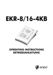
2.3 Keys and connectors
The keys are grouped according to their function:
keys for video management V
keys for telemetry management T
function keys F
Pag. 7
DCJ 4302
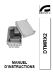
The DCJ keyboard has three RJ11 connectors on the
back of the mechanical part, a power supply
connector, dip-switches for setup and a DB9
connector to update the firmware when necessary.
The VIDEO line controls the video system connected
to the keyboard. Lines A and B control the first and
second telemetry channel respectively.
The dip switches are used to insert or remove the
120 ohm termination load for each of the RS485 lines
(see § RS485 and system types, page 9)
2.4 Second function keys
Some keys (
6, -, .) can be used to activate second functions if pressed simultaneously
with other keys.
For example,
6 means: press the 6 key followed by the key, keeping 6
pressed down. The keys can be released in any order.
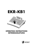
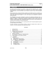
2.5 Dip switch
The back of the keyboard has a set of dip-switches that are used to insert/remove the load of the
RS485 lines and block keyboard programming from the PC. Refer to §3.1 Video and telemetry lines,
page 9, for further information about inserting the line loads.
DIP4: load on Video line
ON: load inserted
OFF: load removed
DIP3: load on Telemetry B line
ON: load inserted
OFF: load removed
DIP2: load on Telemetry A line
ON: load inserted
OFF: load removed
DIP1: internal firmware update
ON: update is possible
OFF: update is not possible
Pag. 8
DCJ 4302
3 Communication lines and connections
3.1 Video and telemetry lines
The DCJ keyboard can be used to control a wide range of products, for both video control (video
matrixes and multiplexers) and telemetry control (receivers and domes). It is therefore necessary to
define the system structure at the keyboard level to achieve efficient communication between the
connected devices.
“Video line” means the communication channel intended to control the video devices; “telemetry
lines” means the two channels available for telemetry control.
We advise starting with the setup of the single “video line” and after that passing to the setup of the
“telemetry lines”.
3.2 RS485 and system types
The RS485 communication channels are 2-wire lines whose maximum length from end to end is
1200m.
The termination of the RS483 lines prevents signal reflection along the cable and should be inserted
in each of the devices that forms the end of a connection.
Systems can be of different types, therefore the way of terminating the lines will also be different.
In the diagrams shown below, the devices requiring termination are indicated by the # symbol.
Setup
Description
Example
Star /
Single lines
For each connection between two
devices there should be a separate
communication line, with a maximum
length of 1200m.
All devices should be terminated, since
each device is connected to an end of
the line
Backbone
A single line is used, and the
transmitters can be placed in any
position along it. The two ends of the
line (keyboard K and receiver R3 in the
example) are terminated; the other
devices (R1 and R2) are not
terminated. The maximum length of the
line is 1200m.
The specifications for the RS485
standard allow at least 32 devices to be
connected along the same line.
Pag. 9
DCJ 4302
Setup
Description
Example
Line with stub
A certain number of stubs can be
shunted in parallel to the normal RS485
line, for connection to other devices.
Since the stubs are not at the ends of
the line, they should not be terminated
and they should be very short in length
(of the order of a couple of metres).
The specifications for the RS485
standard allow at least 32 devices to be
connected along the same line.
Devices in a
chain
The devices are connected in pairs
using single lines. These should be
terminated at the ends. This type of
setup can only be made when the
devices have a separate input
(reception) and output (transmission)
channel, like the Videotec DTRX1 and
DTRX3 receivers.
The received signal is sent “clean” to
the next device. If one device is
blocked, communication is cut off to the
devices later in the chain.
The maximum total length is equal to
the number of lines multiplied by
1200m for each distance.
Mixed setup
It is possible to set up mixed
configurations, always bearing in mind
the limits given above:
each line can have a maximum length
of 1200m
each line should be terminated at the
ends
the stubs should be very short (max.
2m)
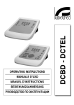
3.3 Standard connection cable
The connection between the DCJ keyboard and the various controlled devices is made only and
exclusively using a RS485 serial channel.
When the controlled device does not provide this channel it will be necessary to insert a signal
converter (e.g. RS486-RS232 or RS485- Current loop) between the keyboard and the device itself.
Connection with the latest generation of Videotec products (video switchers SM42A, SM82A, video
matrix SW328, SM84A, SM164A, etc.) can be made directly using a serial 1.5m telephone cable,
which is supplied.
A pair of telephone cables with a pair of RJjack shunt boxes can be used to arrive at distances of up
to 1200m using the following connection diagram:
Pag. 10
DCJ 4302
DCJ
RJjack 1
RJjack 2
Device
RS485A
White
Blue
RS485A
RS485B
Yellow
Black
RS485B
3.4 One control keyboard per line
Connection is performed by means of one standard connection cable, which is described in the
previous paragraph.
3.5 More than two devices on the same line
The presence of more than one keyboard on the same communication line requires the use of Rjjack
boxes, to be connected in the correct way. As specified in § 3.2 RS485 and system types, page 9,
identify the two devices which represent the line ends and correctly terminate them (to terminate the
DCJ keyboard, see § 2.5 - Dip switch, page 8).
Particular attention must be paid for the length of the stubs.
Transmitters (keyboards)
Receivers
(video matrixes, telemetry)
White
RS485A
Blue
Yellow
RS485B
Black
Pag. 11
DCJ 4302
4 Keyboard setup
Programming is carried out on the keyboard display. The following is a description of the procedure
to start programming the various menu items shown on the display.
4.1 Keys
To enter setup:
-
To move the cursor within the menus:
2 choose the line with the joystick
3 change the value with the joystick
enter the submenu indicated by the cursor
exit to previous menu
To exit setup: press repeatedly.
4.2 Selecting and inserting values
When a menu allows multiple choices, the selected item is indicated by the L symbol.
If a numeric value is to be inserted, it should be confirmed by
last digit inserted, and
. can be used to erase the
to exit without saving. If the numeric value is invalid, an acoustic signal
will warn the operator of the error.
The individual menu items are not displayed when the previous choices make them unnecessary.
4.3 Menu items
Shown on display
Submenu
Description
R (1.8(.,
20081S*(7S216
Choice of menu and message language.
R7(US(12
The selected language is indicated by the *
1.US6/
5(1*(S6
symbol.
,876*/
RR
Definition of devices connected to the
S+,2
keyboard, see § 2.2 - Equipment that can
,U,0,75< US1, be
connected to the DCJ keyboard, page 6
,U,0,75< US1, R R R Parameters for video line; see § 5 - Video
R
management, page 22
<3,D
;;;
5272*2UD ;;;
(+85(7,D ;;;
Pag. 12
DCJ 4302
Shown on display
,U,0,75< US1,6
**,37,+ 9(U8,6
Submenu
Description
PR P
5272*2UD ;;;
211,*7PD ;;;
(8+5(7,D ;;;
PR P
5272*2UD ;;;
211,7PD ;;;
(8+5(7,D ;;;
R
k /(1., 66S.1,0,17
UU 21 US1, UU 21 US1, Parameters for telemetry line A; see § 6.3 Communication problems between
keyboard and receiver, page 44
(0,5(6
21S7256
81*7S216
8U7S3U,;,5
Acceptance of requests for cameras,
monitors, functions and multiplexers.
Acceptance is a very practical way of
limiting keyboard operations, without
having to make use of further system
passwords
,7 ,-(8U7
2+S-< US67
Accepting the request for individual
cameras; see § 4.5 - Accepting requests
for cameras, page 16
R
,7 ,-(8U7
2+S-< US67
Accepting the request for individual
monitors
see § 4.6 - Accepting the request for
monitors, page 18
Parameters for telemetry line B; see § 6.3 Communication problems between
keyboard and receiver, page 44
Assignment of receiver lines; see § 4.4 Assigning the telemetry lines, page 15
R
Accepting the request for functions;
5,9PQ,;7 D ;;
see § 4.8 - Accepting requests for
21S725 /. D ;;
functions, page 18
S+,2 ,783 D ;;
,*,S9P,783D ;;
U(50 ,6,7 D ;;
2<67S*T
D ;;
,16,6
D ;;
8723(1Q*(1D ;;
,*,S9,5 /.D ;;
,U(<6
D ;;
S3,5Q(6/,5D ;;
R Accepting the request for individual
,7 +,-(8U7
multiplexers;
2+S-< US67
see § 4.7 - Accepting the request for
multiplexers, page 18
,<)2(5+ 80),5
RO
80),5D Z JCQ;;K
System identification number of keyboard.
Each keyboard in the system should be
identified by a different number: the
presence of more than one keyboard with
the same number could cause
communication problems.
2<67S*T (US)5P
R RPC
,U,(6, 7/, [2<
(1+ 35,66 17,5
72 *217S18,PPP
*7S9(7S21
US*T 21 T,<5,66
Joystick calibration and test
see § 4.9 - Joystick calibration and test,
page 19
8==,5
Pag. 13
Activation of warning buzzer;
see § 4.10 - Buzzer, page 20
DCJ 4302
Shown on display
(66:25+
7/,5 3(5(0,7,56
(9, (1+ ,;S7
Submenu
Description
27 86,+
1 U(50
1 20 (8U7
1 U(50Q20 P
R
27 86,+
/257
21.
211,*7S21 :+
U(50 ,6,7 :+
,783 :+
R R1387 3(66:25+D
WLL X
R 21-S50 3(66:25+D
WLLL X
2:,56(9S1.
5525 ,66(.,6
S1,6 8727,67
2<67S*T ,67
,025< ,67
S63U(< 2175(67
,783 ,6,7
R
27 86,+
1()U,+
Definition of keyboard passwords;
see § 4.11 - Password, page 20
Concealed password insertion
Concealed password confirmation
Power saving puts the keyboard in low
consumption mode after one minute of
inactivity.
27 6/2:1
8720P 12 8==,5
8720P :S7/ 8==,5
S7/ 21-S50(7S21
R RP
' OOOOO '
D D D
72 ,1+
R D 0S1D 0(;D
D 0S1D 0(;D
D 0S1D 0(;D
(.,D ;;;Q!CC
72 ,1+
R ;;;
RQP/(1.,
CP,-(8U7
P5,9S286 P;S7
Management of warning and error
messages;
see § 4.12 - Warning and error messages,
page 20
2 <28 :(17 72 5,6,7
72 +,-(8U7 *21-S.'
WX WX
Resets factory default values. The reset
operation should be confirmed by the
operator.
Autotest of serial channels
see § 4.13 - Autotest of serial channels,
page 21
Joystick operation test.
The test is described at § 4.9 - Joystick
calibration and test, page 19
Internal memory test, useful in the case of
faulty operation and telephone assistance.
Changes display contrast: press
8 and
9 to alter contrast.
* recalls the previous contrast value
and ! recalls the default value.
Saves new settings and exits menu.
Pag. 14
DCJ 4302
4.4 Assigning the telemetry lines
Since two telemetry lines, A and B, are present, it is necessary to determine which is the line (and
hence also protocol) of reference when a receiver is requested.
The distinction between lines A and B only has any sense if both lines are used; if at least one is
unused any telemetry line assignment setup will be ignored
4.4.1
Default setting
The default setting assigns all receivers to line A: line B is not used.
4.4.2
Assigning all receivers to a single line
It is possible to assign all receivers to a single line in the submenu
R Q UU 21 US1, O :
R
/(1., 66S.1,0,17
k UU 21 S1, UU 21 S1, R
66S.1 (UU ,*,S9,56
72 S1, '
WX WX
4.4.3
Recall the menu by selecting it with the joystick, and press
Select with the joystick and confirm with
.
.
Modifying the list
The modify list menu displays the various sets of receivers to be set up:
R
k ,*,S9PCOC
,*,S9PCCO
,*,S9PCO
It is important to note the three specific symbols on the right of the display:
indicates that all receivers in the group are connected to line A
indicates that all receivers in the group are connected to line B
indicates that some receivers in the group are connected to line A, and some to line B.
There are 999 receivers available, although probably only a smaller number will be present in the
system.
The display in the example shows three sets of receivers: the first from number 1 to number 100; the
second from number 101 to 200, the third from 201 to 300.
The other groups of receivers can be selected by moving the joystick
2.
The cursor k shows the set of receivers being set up:
•
•
!
to assign all receivers in the set to line A press *.
to assign all receivers in the set to line B press
Pag. 15
DCJ 4302
•
If the set of receivers is to be defined more precisely (some receivers in the set are to be
assigned to line A and some to line B), press
•
Press
to subdivide the set shown into smaller sets.
to return to the previous display menus.
4.5 Accepting requests for cameras
Accepting requests for cameras allows keyboard use to be limited solely to authorised input videos
without having to use further system passwords. We recommend defining the accepted input video
groups for each keyboard only after clearly defining the system configuration.
Accepted cameras makes use of a two-level menu:
k ,7 +,-(8U7
2+S-< US67
4.5.1
Default setting
The default setting allows control of all cameras, erasing any previously defined setting.
4.5.2
Modifying the list
Modify list allows more precise definition of the list of cameras that can be requested from the
keyboard.
The modify list menu displays the various sets of cameras to be set up:
k (0P COC
(0P CCO
(0P CO
a
c
b
It is important to note the three special symbols on the right of the display:
b
c
a
indicates that no camera in the corresponding set is accepted
indicates that some cameras in the set are accepted and some are not
indicates that all cameras in the set are accepted.
There are 9999 cameras available: normally a much smaller set of cameras will be used but the
possibility of selection over a wide interval is useful for video management with large sized devices
where the “zone” feature is available.
The display in the example shows three sets of cameras: the first from number 1 to number 1000;
the second from number 1001 to 2000, the third from 2001 to 3000.
The other groups of cameras can be selected by moving the joystick
The cursor k shows the set of cameras being set up:
2.
!.
•
to accept the request for all the cameras in the set press
•
to disable all the cameras in the set press
•
if the set of accepted cameras is to be defined more precisely (some cameras in the set should
be accepted and others not), press
*.
to subdivide the set shown into smaller sets.
Pag. 16
DCJ 4302
•
press
to return to the previous display menus.
The following example shows how to accept cameras 1 to 7, and at the same time disable access to
all the others:
k (0P COC
(0P CCO
(0P CO
a
b
b
All cameras in the 1-1000 set are accepted, while those from
1001 to 3000 are not. Select the 1-1000 set with the joystick
and press
k (0P COC
(0P CCO
(0P CO
b
b
b
* to completely disable all cameras.
2
The icons on the right of the display show that none of the
cameras in the sets from 1 to 3000 are now available on request.
Select the 1-1000 set with the joystick
2 and press to pass
to a more precise definition level.
k (0P COC
(0P CCO
(0P CO
b
b
b
The sets shown on the display are now of 100 cameras each.
None of the cameras in the sets are accepted.
Select the 1-100 set with
2 and press to pass to a more
precise definition level.
k (0P COC
(0P CCO
(0P CO
a
b
b
Select the 1-10 set and press
! to accept all cameras in the
set from 1 to 10.
Then press
to define acceptance at the individual camera
level.
k
(0,5( C
(0,5( (0,5( a
a
a
Since all cameras from 1 to 10 are now accepted, it is necessary
to run through the list with the joystick to disable cameras 8,9,10,
so as to satisfy the requirements of the example.
2 until camera 8 is reached.
Scroll the list with
4.5.3
* to disable camera 8. Continue in the same way to
(0,5( #
k
(0,5( $
(0,5( %
a
b
b
Press
k (0P COC
(0P CCO
(0P CO
c
b
b
After completing modification, pressing
disable cameras 9 and 10.
will return to the
previous menu and then again on up to the main menu.
The icon of the 1-10 set has now been changed to c to show that
only some of the cameras in the group are now accepted.
Warning message
If a disabled camera is requested, the display will show a message warning the operator that the
request is not authorised:
Pag. 17
DCJ 4302
(0,5( CC
S6 +S6()U,+>
35,66 4.6 Accepting the request for monitors
Accepting the monitors is used to prevent an unauthorised operator from operating monitors that are
not within his duties.
4.6.1
Default setting
The default setting allows control of all monitors, erasing any previously defined setting.
4.6.2
Modifying the list
The procedure for accepting and disabling the monitors is the same as that just described for the
cameras (see § 4.5 - Accepting requests for cameras, page 16).
Usually 99 monitors can be selected from the keyboard.
4.7 Accepting the request for multiplexers
Accepting the multiplexers is used to prevent an unauthorised operator from operating multiplexers
that are not within his duties.
4.7.1
Default setting
The default setting allows control of all multiplexers, erasing any previously defined setting.
4.7.2
Modifying the list
The procedure for accepting and disabling the multiplexers is the same as that just described for the
cameras (see § 4.5 - Accepting requests for cameras, page 16).
Usually 39 multiplexers can be selected from the keyboard.
4.8 Accepting requests for functions
Each operator can be enabled (or not) to carry out specific operations from the keyboard.
These are divided into groups of functions and are:
5,9Q,;7: enabling camera selection with the
9 and 8 keys; since these keys are able to
cause a break in the automatic sequence it may be necessary to disable them if this likelihood is to
prevented.
21S725 /.P: enabling monitor change; if an operator has a single monitor, this can be frozen so
that it cannot be changed any more.
S+,2 ,783: enabling video device (switcher or matrix) setup; even if enabled this can be subject
to insertion of a password
,*,S9P,783: enabling dome or telemetry receiver setup; if enabled this can also be subject to a
password
U(50 ,6,7: enabling reset of video device alarms; if enabled this can also be subject to a
password
2<67S*T: enabling use of joystick
Pag. 18
DCJ 4302
,16,6 enabling control of lens functions in telemetry receivers
8723(1Q*(1: enabling changes to pan & tilt /dome movement by sending autopan and scan
type commands
,*,S9,5 /.: enabling change to receiver number associated with a camera
,U(<6: enabling relays control
S3,5Q(6/,5: enabling wiper and washer control.
4.9 Joystick calibration and test
Joystick calibration is process which allows correct operation of the device. Normally it is only done
at the production stage and recalibration by the operator should never be necessary. If the joystick
behaves incorrectly (if, for example, a pan or tilt direction stays active when the joystick is at rest) it
may be necessary to carry out the calibration procedure.
R RP C
,U,(6, 7/, [2<
,(1+ 35,66 17,5
72 *217S18,PPP
First stage: with the joystick at rest (released) press
will specify the point at rest. Pressing
. This
will pass to testing
without continuing with calibration.
R RP 29, 7/, [2<
21 7/, *251,56
R RP O !C ! M!
O! ! " M! "
17,5 72 ,1+
After pressing
, move the joystick without forcing it until it
reaches its maximum extension upwards, downwards, to the right
and to the left.
During movement the values for certain readings will appear on
the display. These are of no interest to the operator unless there
is faulty operation, in which case they may be useful for
telephone assistance. The joystick should be moved until the
values given for O, M, O and M (values that show the limit
points to the left, right, bottom and top) do not change when the
joystick is moved. The values shown in the centre of the display
change continually when the joystick is moved.
will pass to the next stage of setup.
Pressing will pass to testing without completing calibration.
Pressing
R RP 27(7, *U2*T:S6,
(1+ *2817,5*U2*T:S6,
17,5 72 ,1+
During normal operation, activation of the zoom will correspond
to rotation of the joystick.
R RP O$C ! M!
17,5 72 ,1+
Rotate the joystick until the two extremes are reached several
times, until the values shown by O and M (limit points for the
counterclockwise and clockwise directions) do not change.
Pressing
will complete setup and pass to testing, pressing
will pass to testing without recalibrating the zoom.
R D 0S1D 0(;D
D 0S1D 0(;D
D 0S1D 0(;D
Joystick test: after calibration this enables the operator to check
whether calibration was successful.
Pag. 19
DCJ 4302
With the joystick at rest the values shown by D, D and D
should be equal to 0. Move the joystick until the limit is reached in
the four directions and rotate it to the limit in the clockwise and
counter-clockwise directions. If, after these operations, the three
0S1D parameters and the three 0(;D parameters show calibration was successful.
Otherwise it is advisable to recalibrate the joystick since a setup
error in the joystick will affect its operation.
4.10 Buzzer
The keyboard is equipped with a buzzer for acoustic signals when abnormal situations occur.
The buzzer can be enabled to:
•
recognise video device (switcher or matrix) alarm status
•
recognise a break in communications with the video device
•
give a small warning click when a key is pressed.
It should be noted that alarm status and breaks in communication are only available for some of the
video devices available for connection: SM42A, SM82A, SM84A, SM164A, SW164OSM, SW328.
4.11 Password
Keyboard security is managed by three password levels:
•
connection password: requested when the keyboard is switched on, it is used to prevent
improper use of the keyboard by unauthorised personnel
•
setup password: requested whenever it is necessary to carry out a setup. For connection with
certain video devices (switchers SM42A / SM82A and matrix SM84A / SM164A) the password is
not requested since it is managed directly at the video device level: in this case it should be
inserted as described in the manual for the controlled device
•
reset alarm password: requested when an alarm has to be cleared.
Passwords are defined at the individual keyboard level, and may therefore differ for each operator.
They can be disabled (default status, when leaving the factory) by setting to 00000.
Warning: it is not possible to retrieve a setup password that is lost or forgotten.
4.12 Warning and error messages
The keyboard will advise the operator of a requested operation failure by messages on the display.
These messages can be set up in four different ways:
•
disabled messages: messages are not shown
•
automatic message without warning beep: the message will be shown for about 3 seconds and
will then disappear automatically without the acoustic signal; it can be removed in advance by
pressing
•
.
automatic message with warning beep: the message will be shown for about 3 seconds and is
accompanied by a beep; it will disappear automatically and can be removed by pressing
•
.
message with confirmation: the message is accompanied by a warning beep and only
disappears when the operator presses
.
Pag. 20
DCJ 4302
4.13 Autotest of serial channels
In the case of faulty operation or to check the keyboard, it is possible to carry out a simple test to
make sure the communication channels to the video device and the telemetry are working perfectly.
Disconnect any devices connected to the V, A and B lines and make up the following test cable,
using two telephone cables and two RJjack boxes supplied with the keyboard:
Phone cable
RJjack 1
RJjack 2
Phone cable
RS485A
White
White
RS485A
RS485B
Yellow
Yellow
RS485B
Warning: this cable is different from the standard connection cable described in § 3.3 Standard connection cable, page 10
4.13.1 Autotest procedure
1) Connect the cable to connectors A and B
2) Connect the cable to connectors A and V
3) Connect the cable to connectors B and V.
R RP
FOOOG D'' D D
72 ,1+
The display shows FOOOG .
This means that input and output communication lines for the two
lines are functioning correctly.
R RP
OOOOG D D' D'
72 ,1+
Other types of message mean that the connecting cable is
incorrect or that the test lines are not working. In the example
channel A is able to transmit and B receives correctly, but
communication is only in one direction.
R RP
FOOOG D D D
72 ,1+
The third line shows the results of the test: D, D and D stand
for the three lines - Video, Telemetry B and Telemetry A
respectively.
For each line, A, B and V, one of the following messages will be shown:
'': the line is not working and is unable to transmit or receive data
': the line is able to transmit but not receive
': the line receives but is unable to transmit
: the line transmits and receives correctly.
Pag. 21
DCJ 4302
5 Video management
The back of the keyboard has a VIDEO connector to control the video devices. It is necessary to set
up both the keyboard and the controlled device correctly, since both the chosen communication
protocols and speeds (baud rate) should be the same.
If these parameters are set up incorrectly, communication between the devices is impossible.
5.1 Description of the display
The DCJ keyboard display shows all the information required by the operator.
A typical display is as follows:
C
RP C
R x
The four rows show, respectively:
: the last camera selected by the operator.
If an icon appears, and not a number, this means that specific functions have been requested:
•
icon de: next camera expected by the sequence
•
icon fg: previous camera expected by the sequence
•
icon ih: automatic sequence
RD telemetry receiver associated with camera; all telemetry operations are directed to this
receiver
R: active monitor; all video operations are directed to this monitor
Message line ( in the example): alarm messages and the keys pressed are shown on this
line.
The x symbol stands for the joystick position at rest and changes as the joystick moves.
5.2 Video: fundamental concepts
The DCJ keyboard allows two fundamental types of operations for controlling the video signal:
•
selection of a camera on the active monitor
•
starting a preset automatic sequence on the active monitor
All operations requested by the keyboard refer to the active monitor, which is always shown on the
display.
Camera selection is subject to the setup of accepted cameras. If a camera is not accepted for the
request, the selection attempt is accompanied by an error message; see § 4.5.3 - Warning message,
page 17.
Note that not all the functions are accepted by the different video devices (switchers and matrix).
When a requested function is not allowed for a video device, an error message warns the operator
that it is impossible to carry out the command.
Pag. 22
DCJ 4302
5.2.1
Direct selection of a camera
followed by the camera number and confirm with .
For example: !" selects camera 12 on the active monitor.
When possible, insertion is completed automatically without waiting for the key.
Press
5.2.2
Selecting the previous/next camera
9 and 8 keys select, respectively, the previous and next cameras as set up in the
automatic sequence preset at the video device level. If the automatic sequence is in progress, the
first time the 9 and 8 keys are pressed, it will be halted.
The 9 and 8 keys can be disabled and are managed the most recent versions of the video
The
devices (switchers SM42A, SM82A and matrix SM84A, SM164A).
If the keys are pressed for the other video devices, they will be ignored.
5.2.3
“Views”
Views can be used to carry out a series of four operations by pressing only one key:
•
selection of a new active monitor
•
selection of a camera on the new active monitor
•
selection of the receiver associated with the camera
•
scan operation on a pan & tilt position that is already stored in the receiver.
If the views are set up correctly this will speed up operations by making 10 preset
camera/monitor/receiver/scan operations available to the operator.
! is associated with camera 12
(which usually corresponds to receiver 12), monitor 3 and scan 5, just pressing key ! will replace
The use of views is especially useful in alarm situations: if key
the sequence
# !" !" %.
By pressing the key the operator will therefore be able to quickly recall a preset position defined on a
monitor.
Defining the views
Views are set up by pressing three keys simultaneously, from
6-* to 6-), if
the operator is authorised to set up the views.
The display shows the current setup of the view for about one second, and then passes to the
request for new parameters:
R PC
(0,5(
C
21S725 O
*(1
O
The display in the example illustrated here shows that when key
1 is pressed, this is a request for camera 1 on the active monitor
(the O symbol means that no monitor in particular is requested for
the operation) and there is no request for a scan for the pan & tilt
associated with the camera (the O symbol next to the word
*(1).
Pag. 23
DCJ 4302
R PC
(0,5(
CZ
21S725 O
*(1
O
Inserting the camera.
Insert a number or press
to confirm the previously defined
number.
R PC
(0,5(
C
21S725 Z
*(1
O
Inserting the monitor.
Insert a number or press
to confirm the previously defined
number. If the number 0 is inserted this means the active monitor
will not be changed when the view is requested.
R PC
(0,5(
C
21S725 *(1
!Z
Inserting the scan position.
Insert a number or press
to confirm the previously defined
number. If the number 0 is inserted this means no scan operation
will be requested when the view is requested.
Requesting the views
Press a key from
* to ) to request the corresponding view.
Erasing the customised views
Press keys
6- simultaneously.
The default settings for the views can be used to recall cameras 1 to 9 directly without changing the
active monitor and without making scans. The
5.2.4
* recalls camera 10.
Receivers associated with the cameras
To each camera is associated a telemetry receiver.
It is possible for one receiver to be present for each camera and this receiver is assigned
permanently at the system installation stage. When the camera-receiver association has been
defined it should never be changed unless there are changes to the system itself.
The installation procedure normally expects the assignment of a receiver number corresponding to
that of the video input (for example, camera number 10 is controlled by receiver number 10), but the
assignment may be more flexible.
Every time a camera has been requested and following this selection a new receiver number is
requested, this receiver number will be “remembered” by the keyboard. If requesting a different
receiver number from the pre-assigned number is not to be allowed, we advise disabling the setup
menu option: **,37,+ 9(U8,6 Q 81*7S216 Q ,*,S9P*/.
For example:
!
C
RP C
R x
Camera 1 has been requested. The display
shows that the receiver currently associated
with this camera is number 1.
%
C
RP !
R x
If the operator is authorised to do so, he can
assign another receiver number to the camera;
if not the display shows an error message.
Pag. 24
DCJ 4302
"
RP R x
Camera 2 has been requested, and the display
shows that it is currently associated with
receiver 2.
!
C
RP !
R x
Following the new request for camera 1 the last
receiver associated with camera 1 is shown.
Pag. 25
DCJ 4302
5.3 Video matrix SM84A and SM164A
5.3.1
Description
Matrix SM84A and SM164A are products for professional use in applications for security and
surveillance and dedicated to the management of video signals. The SM84A and SM164A models
differ only in the number of possible video input connections, 8 and 16 respectively; there are four
video outputs, one of which can be managed directly by a VCR.
As well as the usual switching, alarm management and on screen menu programming operations,
the SM84A / SM164A matrix is equipped with an optional auxiliary line that can be used to control
the telemetry or multiplexer units. Refer to the matrix manual for further information on this subject.
5.3.2
Connexion
Cable
The communication cable is standard, as described in § 3.3 - Standard connection cable, page 10.
Matrix settings
The new generation matrix SM84A / SM164A can be controlled by different types of keyboard and
therefore emulates the respective protocols: to control the switcher with the DCJ keyboard the
MACRO protocol with baud rate 38400 should be used.
Set the dip switches in the matrix as required (all dips are OFF, with the exception of Macro Protocol,
baud rate 38400, programming).
Keyboard settings
While the keyboard is being set up, the RR
set as follows:
Q R R
R R RP
<3,D
$Q
5272*2UD (*52
(8+5(7,D $ Control of a SM84A matrix
R R RP
<3,D
C"Q
5272*2UD (*52
(8+5(7,D $ Control of a SM164A matrix
submenu should be
The presence of a maximum of four keyboards connected to the matrix means it is necessary to
define a different identification number for each one (from 1 to 4).
Operational test
If the keyboard is connected directly with the switcher set up in this way using the telephone cable
supplied, it should be possible to switch the input videos immediately:
•
•
! to select monitor 1
press !, ", to select the cameras.
press
Pag. 26
DCJ 4302
5.3.3
Video device setup
The setup procedure is described in the video device’s instruction manual.
Press
- to enter setup, and insert setup password if it has been enabled.
Pag. 27
DCJ 4302
5.4 Switchers SM42A and SM82A
5.4.1
Description
Switchers SM42A and SM82A are products dedicated to the management of video signals. The
SM42A and SM82A models differ only in the number of possible video input connections, 4 and 8
respectively; there are two video outputs, one of which can be managed directly by a VCR.
As well as the usual switching, alarm management and on screen menu programming operations,
the SM42A / SM82A switcher is equipped with an optional auxiliary line that can be used to control
the telemetry or multiplexer units. Refer to the switcher manual for further information on this subject.
5.4.2
Connection
Cable
The communication cable is standard, as described in § 3.3 - Standard connection cable, page 10
Switcher settings
The new generation switcher SM42A / SM82A can be controlled by different types of keyboard and
therefore emulates the respective protocols: to control the switcher with the DCJ keyboard the
MACRO protocol with baud rate 38400 should be used.
Set the dip switches in the switcher as required (all dips are OFF, with the exception of Macro
Protocol, baud rate 38400, programming).
Keyboard settings
While the keyboard is being set up, the RR
as follows:
Q R R submenu should be set
R R RP
<3,D
Q
5272*2UD (*52
(8+5(7,D $ Control of a SM42A switcher
R R RP
<3,D
$Q
5272*2UD (*52
(8+5(7,D $ Control of a SM82A switcher
The presence of two keyboards connected to the switcher means it is necessary to define two
different identification numbers (from 1 to 4).
Operational test
If the keyboard is connected directly with the switcher set up in this way using the telephone cable
supplied, it should be possible to switch the input videos immediately:
•
•
! to select monitor 1
press !, ", to select the cameras.
press
Pag. 28
DCJ 4302
5.4.3
Video device setup
The setup procedure is described in the video device’s instruction manual.
Press
- to enter setup, and insert setup password if it has been enabled.
Pag. 29
DCJ 4302
5.5 Video matrix Linxs LXRPS84A and LXRPS164A
5.5.1
Description
Matrix LXRPS84A and LXRPS164A are products for professional use in applications for security and
surveillance and dedicated to the management of video signals. The LXRPS84A and LXRPS164A
models differ only in the number of possible video input connections, 8 and 16 respectively; there are
four video outputs, one of which can be managed directly by a VCR. They are used to control the
usual switching, alarm management and on screen menu programming operations. Refer to the
matrix manual for further information on this subject.
5.5.2
Connection
Cable
The communication cable is standard, as described in § 3.3 - Standard connection cable, page 10.
Matrix settings
The baud rate of the matrix can be selected by the dip switch SW1 inside the matrix:
• dip 6 off: 9600 baud (default status)
• dip 6 on: 1200 baud
Operations to modify the baud rate should be carried out after disconnecting the power supply to the
matrix. Refer to the respective manual.
Keyboard setting
While the keyboard is being set up, the RR
set as follows:
Q R R
R R RP
<3,D
$Q
5272*2UD S1;6
(8+5(7,D %"
Control of a LXRPS84A matrix
R R RP
<3,D
C"Q
5272*2UD S1;6
(8+5(7,D %"
Control of a LXRPS164A matrix
submenu should be
the baud rate is normally 9600 baud
the baud rate is normally 9600 baud
Even in the presence of more than one keyboard connected to the matrix, the identification number
of each keyboard is of no importance.
Operational test
If the keyboard is connected directly with the matrix set up in this way using the telephone cable
supplied, it should be possible to switch the input videos immediately:
•
•
! to select monitor 1
press !, ", to select the cameras.
press
Pag. 30
DCJ 4302
5.5.3
Video device setup
Connect a camera to input no.1 and a monitor to output no.1, as specified in the video device’s
instruction manual.
Press
- to start the setup then insert the setup password if it has been enabled.
Keyboard’s display shows the mode change:
R R R
72 ,1+
: setup end
Joystick 2: choice of a menu line
Joystick 3: enter submenus and change of values
Key : confirm choice when this is necessary
Keys !..(: direct value (ie. during password change)
Key
Pag. 31
DCJ 4302
5.6 Switchers Linxs LXRPS42A and LXRPS82A
5.6.1
Description
Switchers LXRPS42A and LXRPS82A are products for professional use in applications for security
and surveillance and dedicated to the management of video signals. The LXRPS42A and
LXRPS82A models differ only in the number of possible video input connections, 8 and 4
respectively; there are two video outputs, one of which can be managed directly by a VCR. They are
used to control the usual switching, alarm management and on screen menu programming
operations. Refer to the switcher manual for further information on this subject.
5.6.2
Connection
Cable
The communication cable is standard, as described in § 3.3 - Standard connection cable, page 10.
Switcher settings
The baud rate of the switcher can be selected using the bump contact JP1 inside the switcher:
• bump contact open: 9600 baud (default status)
• bump contact shorted: 1200 baud
Operations to modify the baud rate should be carried out after disconnecting the power supply to the
switcher. Refer to the respective manual.
Keyboard settings
While the keyboard is being set up, the RR
set as follows:
Q R R
R R RP
<3,D
Q
5272*2UD S1;6
(8+5(7,D %"
Control of a LXRPS42A matrix
R R RP
<3,D
$Q
5272*2UD S1;6
(8+5(7,D %"
Control of a LXRPS82A matrix
submenu should be
the baud rate is normally 9600 baud
the baud rate is normally 9600 baud
Even in the presence of more than one keyboard connected to the switcher, the identification
number of each keyboard is of no importance.
5.6.3
Operational test
If the keyboard is connected directly with the switcher set up in this way using the telephone cable
supplied, it should be possible to switch the input videos immediately:
•
•
! to select monitor 1
press !, ", to select the cameras.
press
Pag. 32
DCJ 4302
5.6.4
Video device setup
Connect a camera to input no.1 and a monitor to output no.1, as specified in the video device’s
instruction manual.
Press
- to start the setup then insert the setup password if it has been enabled.
Keyboard’s display shows the mode change:
R R R
72 ,1+
: setup end
Joystick 2: choice of a menu line
Joystick 3: enter submenus and change of values
Key : confirm choice when this is necessary
Keys !..(: direct value (ie. during password change)
Key
Pag. 33
DCJ 4302
5.7 Video matrix SW328
5.7.1
Description
Matrix SW328 is a product for professional use in applications for security and surveillance and
dedicated to the management of video signals. It can be used to control 32 input videos; there are
eight video outputs, one of which can be managed directly by a VCR. It is used to control the usual
switching and alarm management operations. Refer to the matrix manual for further information on
this subject.
5.7.2
Connection
Cable
The communication cable is standard, as described in § 3.3 - Standard connection cable, page 10.
Matrix settings
No setting is necessary.
Keyboard settings
While the keyboard is being set up, the RR
set as follows:
R R RP
<3,D
Q$
5272*2UD S+$
(8+5(7,D %"
Q R R
submenu should be
Control of a SW328 matrix
The baud rate is fixed at 9600 baud.
The presence of more keyboards connected to the switcher means it is necessary to define a
different identification number for each (from 1 to 8).
Operational test
If the keyboard is connected directly with the switcher set up in this way using the telephone cable
supplied, it should be possible to switch the input videos immediately:
•
•
! to select monitor 1
press !, ", to select the cameras.
press
Warning! Matrix SW328 can be set up so as to exclude control by the keyboard during certain
periods of the day or in specific situations. In this case switching will be impossible. Refer to
the respective manual.
5.7.3
Matrix setup
A remote keyboard can only set date and time on matrix SW328
To change date and time press
-.
: move the cursor to the next position
Key : move the cursor to the previous position
Keys 8/9: increase/decrease the value.
Key
Pag. 34
DCJ 4302
5.8 Video matrix SW164OSM
5.8.1
Description
Matrix SW164OSM is a product for professional use in applications for security and surveillance and
dedicated to the management of video signals. It can be used to control 16 input videos; there are
four video outputs, one of which can be managed directly by a VCR. It is used to control the usual
switching and alarm management operations. Refer to the matrix manual for further information on
this subject.
5.8.2
Connection
Cable
The connection between the matrix and the keyboard is made using an RS232 channel, which limits
its length to about 15 metres. It is necessary to create a connection cable, which is inserted between
DB9 on the back of the keyboard and one of the RJ11 connectors on the back of the matrix.
DCJ
DB9
RJjack
SW164OSM
RX
2
yellow
TX
TX
3
white
RX
GND
5
red
GND
Alternatively, it is possible to use RS485-RS232 interfaces, which allow a maximum distance
between keyboard and matrix of 1200 metres. In this case the connection diagram is as follows:
DCJ
RS485A
RS485B
RJjack 1
White
Yellow
Interface
RJjack2
SW164OSM
IN
OUT
A
RX
yellow
TX
TX
white
RX
GND
red
GND
B
Pag. 35
DCJ 4302
Matrix settings
Inside the matrix, both jumpers JP1 and JP2 should be set up for RS232 type communication, as
shown in the drawing.
Dip switch SW1 is used to select the baud rate:
Baudrate
dip 3
dip 4
9600 baud
ON
ON
1200 baud
OFF
ON
Refer to the respective manual for further information.
Keyboard settings
While the keyboard is being set up, the RR
set as follows:
R R RP
<3,D
C"Q
5272*2UD S+,2
(8+5(7,D %"
Q R R
submenu should be
Control of a SW164OSM matrix.
Even in the presence of more than one keyboard connected to the matrix, the identification number
of each keyboard is of no importance.
Operational test
If the keyboard is connected directly with the switcher set up in this way using the telephone cable
supplied, it should be possible to switch the input videos immediately:
•
•
5.8.3
! to select monitor 1
press !, ", to select the cameras.
press
Matrix setup
Connect a camera to input no.1 and a monitor to output no.1, as specified in the video device’s
instruction manual.
Press
- to start the setup then insert the setup password if it has been enabled.
Keyboard’s display shows the mode change:
R
72 ,1+
Key
: setup end
To maintain compatibility to previous keyboards the usual meaning of DCJ keys was in a few cases
changed.
The following table shows the indications read on monitor during setup, the corresponding
DCS2/KEYPLUS keys, and the new keys used on DCJ:
Pag. 36
DCJ 4302
On screen menu
Meaning
numbers 1..9
choice of cameras 1..9
number 0
choice of camera 10
numbers 11..16
choice of cameras 11..16
DCS2
KEYPLUS
4 (id-text menu only) move cursor up
9 (id-text menu only) move cursor down
8 (id-text menu only) move cursor left
0 (id-text menu only) move cursor right
PROG
PROG key
ENT
ENTER key
CLR
CLEAR key
M/A
Automatic sequence
9 (arrow up)
previous/increase
; (arrow down)
next/decrease
Pag. 37
..
)..
)
"
DCJ
!..)
*
-*..-&
$
Joystick Down or )
Joystick Left or (
Joystick Right or *
8
9
Joystick Up or
DCJ 4302
5.9 Video multiplexer Javelin/Hitron
5.9.1
Description
The Javelin/Hitron multiplexer allows the connection of 16 input videos, which are digitalized and
shown as a composite image at output. A spot service monitor supplies the display of one of the
inputs.
Communication from keyboard to multiplexer is one-way. It is necessary to determine whether the
connected multiplexer is a black & white or colour model, since the specifications and protocols are
different in the two cases.
It is also possible to control the multiplexer indirectly, using a new generation video matrix from the
SM series (SM42A, SM82A, SM84A, SM164A). This type of control is described in § 5.11 Controlling the multiplexer using a video device, page 41.
5.9.2
Direct connection
Cable
DCJ
RJjack 1
RJjack 2
JAVELIN
RS485A
White
Black
RS485A
RS485B
Yellow
Green
RS485B
The connection is of the RS485 type (one-way) and the maximum distance between keyboard and
multiplexer is 1200 metres.
Multiplexer settings
The Javelin multiplexer is available in two versions that differ in their control protocol.
It can only be set up using the local multiplexer keyboard.
See the respective manual.
Keyboard settings
While the keyboard is being set up, the RR
set as follows:
R R RP
<3,D
8;
5272*2UD (9P 2U
(8+5(7,D %"
Q R R
submenu should be
Control of a Javelin/Hitron multiplexer
It is necessary to specify whether the multiplexer is a colour
model (9P2U) or black & white ((9PQ).
Four baud rate values are available.
Pag. 38
DCJ 4302
It is only possible to connect one keyboard to each Javelin multiplexer, and therefore the
identification number of the keyboard is of no importance. More than one multiplexer can be
controlled by the same keyboard, as long as they are identified by different unit numbers.
Operational test
If the keyboard is connected directly with the multiplexer set up in this way using the cable as
indicated above, it should be possible to switch the input videos immediately:
•
•
! to select multiplexer unit 1
press !, ", to select the input videos.
press
Each command sent by the keyboard corresponds to the lighting up of an LED on the local
multiplexer keyboard.
Warning! If the number of the multiplexer unit does not coincide with the commands sent
from the keyboard, they will be ignored.
5.9.3
Dedicated functions
As well as the normal procedure for selecting input videos, the Javelin/Hitron multiplexer is equipped
with numerous other functions that can be activated by pressing key combinations, and that
correspond to the keys present on its local keypad.
The
key is used to change the number of the unit responding to the command.
Only some of the functions given below are available for both models of the multiplexer. Refer to the
multiplexer manual for further information.
6 live record, - vcr, . spot monitor
select, - double select
- menu
. spot monitor output, auto, - full, . freeze
6* “2nd” key, 6! pip1, 6" 2x2, 6# 3x3
6$ 4x4, 6% pip2, 6& zoom, 6' 3+4
6( 2+8, 6) set.
Pag. 39
DCJ 4302
5.10 Video multiplexer SP16C
5.10.1 Description
The SP16C allows the connection of 16 input videos, which are digitalized and shown as a
composite image at output. A spot service monitor supplies the display of one of the inputs.
Communication from keyboard to multiplexer is one-way.
It is also possible to control the multiplexer indirectly, using a new generation video matrix from the
SM series (SM42A, SM82A, SM84A, SM164A). This type of control is described in § 5.11 Controlling the multiplexer using a video device, page 41.
5.10.2 Connexion
Cable
DCJ
RJjack 1
RJjack 2
SP16C
RS485A
White
Black
RS485A
RS485B
Yellow
Yellow
RS485B
The connection is of the RS485 type (one-way) and the maximum distance between keyboard and
multiplexer is 1200 metres.
Multiplexer settings
The multiplexer can only be set up using the local multiplexer keyboard.
See the respective manual.
Keyboard settings
While the keyboard is being set up, the RR
set as follows:
R R RP
<3,D
8;
5272*2UD S+,27,*
(8+5(7,D %"
Q R R
submenu should be
Control of a SP16C multiplexer
Four baud rate values are available.
It is only possible to connect one keyboard to each SP16C, and therefore the identification number of
the keyboard is of no importance.
Pag. 40
DCJ 4302
Operational test
If the keyboard is connected directly with the multiplexer set up in this way using the cable as
indicated above, it should be possible to switch the input videos immediately:
press
!, ", to select the input videos.
Each command sent by the keyboard corresponds to the lighting up of an LED on the local
multiplexer keyboard.
5.10.3 Dedicated functions
As well as the normal procedure for selecting input videos, the SP16C is equipped with numerous
other functions that can be activated by pressing key combinations, and that correspond to the keys
present on its local keypad.
6 live, - vcr
6" function 1+12 / top
6$ function 3x3 / left
6& function 4x4 / right
6( function 2x2 / bottom
- full/zoom
sel
auto
5.11 Controlling the multiplexer using a video device
The multiplexer can be controlled using a
new generation video device from the SM
series (SM42A, SM82A, SM84A, SM164A).
In order to control a multiplexer in this way,
the MACRO protocol must be used.
In this case control may refer equally to the video matrix or the multiplexer. Therefore the choice of
active monitor should be made differently in each case.
5.11.1 Selecting a monitor connected to the video matrix
Press
, followed by the monitor number and if correct confirm with .
After selecting a monitor the display will show the word R, followed by the monitor number.
Only monitors that have been defined as “enabled” in the can be requested.
Pag. 41
Q R menu
DCJ 4302
5.11.2 Selecting a monitor connected to the multiplexer
To each multiplexer corresponds a single main monitor. To use the optional spot monitor see the
respective users’ manual..
If the multiplexer is identified by an address (Javelin/Hitron multiplexer for example), press
6, followed by the multiplexer address and if correct confirm with .
If the multiplexer is not identified by an address (a SP16C mux for example) press
and if correct confirm with
.
6!
After selecting a multiplexer the display will show the word R, followed by the multiplexer
number.
Only multiplexers that have been defined as “enabled” in the can be requested.
Pag. 42
Q R menu
DCJ 4302
6 Telemetry control
6.1 Controlling the telemetry directly and using video systems
Using the SM series of switchers e matrix (SM42A, SM82A, SM84A, SM164A) it is possible to
control a telemetry line directly from the video device. This saves an output telemetry cable from the
keyboards. This series of switchers can also be used for the transmission of telemetry commands on
the video signal coax.
Control is of the traditional type, with the keyboard controlling two
distinct communication channels: receiver R1 is controlled by
keyboard line A; the VIDEO line controls the SM matrix.
There are two output cables from the keyboard.
The video cable of camera C1 can pass through video signal
management devices such as video multiplexers, video
distributors, twisted pair transmitters, etc.
Telemetry control is carried out by the AUX outlet of the video
matrix.
There is only one output cable from the keyboard.
The SM matrix should be set up to retransmit the telemetry
messages using the MACRO or VIDEOTEC protocol. Receiver
R1 should be able to recognise the transmitted protocol (MACRO
or VIDEOTEC).
Communication between keyboard and matrix can only use the
MACRO protocol.
The video cable of camera can pass through video signal
management devices such as video multiplexers, video
distributors, twisted pair transmitters, etc.
Telemetry line A (or B) is set up to transmit messages along the
video cable, so that the A (or B) connector on the back of the
keyboard may not be used to address other telemetry devices,
but should be left without a connection.
Pag. 43
DCJ 4302
Telemetry control is carried out by the transmitted output signals
from the video matrix to the coax cable. There is only one output
cable from the keyboard.
The SM matrix should be set up to retransmit the telemetry
messages using the FSK protocol along the video input cables.
Receiver R1 should be fitted with the DTCOAX decodification
card.
Communication from keyboard to matrix can only use the
MACRO protocol.
The video cables from the receivers to the matrix may not pass
through any device and must be direct.
Telemetry line A (or B) is set up to transmit messages along the
video cable, so that the A (or B) connector on the back of the
keyboard may not be used to address other telemetry devices,
but should be left without a connection.
6.2 Common telemetry operations
Telemetry operations are divided into different categories:
• setup operations (receiver/dome setup, preset, etc.)
• manual handling operations (pan & tilt)
• automatic handling operations (autopan, scan, patrol, etc.)
• lens control operations
• relay and auxiliary contact control operations.
The keyboard can be enabled or disabled for the request of each group of operations. If an operation
belonging to a disabled group is requested, the display will show an error message.
In the following text the term “receiver” refers to any device set up to receive telemetry commands.
6.2.1
Changing the active receiver
Telemetry commands are always directed to the active receiver, shown on the display.
If the keyboard is enabled to make a change, press
and insert a new active receiver number.
6.3 Communication problems between keyboard and receiver
If a receiver does not respond to the commands it will be necessary to check:
•
does the receiver model connected to the telemetry line (A or B) use the protocol setting for the
telemetry line?
•
does the receiver number correspond to that shown on the display?
•
does the receiver baud rate correspond to the setting for the telemetry line?
•
does the telemetry line in question output to a video cable or to a dedicated connector?
•
has the connection between keyboard and receiver been implemented correctly?
•
if the line passes through an SM matrix, has the matrix been set up correctly?
Pag. 44
DCJ 4302
6.4 Notes regarding telemetry control
6.4.1
Special codes
The DCJ keyboard can be used to control a considerable number of telemetry functions, and to
recall some of these there are no suitable key combinations.
They can therefore be activated by using the following procedure:
7 key
•
press the
•
insert the numeric code
confirm with
The
6.4.2
.
5555 corresponding to the required function and
key cancels the code insertion operation.
Typographical conventions
75555 (min÷max) means that it is possible to insert numeric
codes between the specified min and max limit: for example 7"*55 (0÷19)
means that it is possible to insert special codes from 2000 to 2019. For each 5 symbol, a
The indication
numeric digit should be inserted.
The terms “Video programming”, “On Screen Menu” and “OSM” should be considered equivalent: in
the dome user’s manual these terms are interchangeable.
Pag. 45
DCJ 4302
6.5 Elmo dome
6.5.1
Reference material and documents
Dome D7720B-J1P
Surveillance Control Protocol (DSCP), ver2.4, 2001.05.25
6.5.2
Connection
Cable
White
RS485A
Red
Yellow
RS485B
Black
Red
GND
Green
Warning!
Both phone-cables (one connected to the keyboard, the other to the dome) are supplied as standard
with the DCJ keyboard. DO NOT USE the grey phone cable included in the ELMO dome equipment;
its use can cause the damage of the keyboard.
Dome settings
Dome ID-number must be set according to the respective installation manual.
Keyboard settings
During Keyboard setup, submenu RR
set:
PR O P
5272*2UD U02
211,*7PD ,UPO
(8+5(7,D %"
6.5.3
Q R O, must be suitably
Baudrate is fixed (9600 baud).
Setup
Dome setup is mostly carried out by On Screen Menu.
Some parameters can be set up by pressing a combination of keys or by inserting a special code.
For all setup operations the keyboard must be enabled to perform the receiver setup (menu
**,37,+ 9(U8,6 Q 81*7S216 Q ,*,S9P,783).
OSM Setup
Connect the dome directly to the keyboard and connect a monitor to the dome video outlet.
The DCJ keyboard enters special mode while the dome is being set up. When
is pressed for
the first time, the keyboard is reset to normal operation.
Pag. 46
DCJ 4302
- starts dome setup.
The dome shows the menu on video; the keyboard shows the mode change on the display:
6* 72 ,1+
end setup
enter submenu
Joystick 2: shifts the cursor within the menus
Joystick 3: changes the value shown by the cursor.
When dome movement is required in OSM mode, the 6 key should be held down while the
joystick is being moved 4.
Activation of Zoom Tele and Zoom Wide, when required, is obtained by rotating the joystick 1.
Direct setup
Some parameters can be set up by pressing the keys or inserting a special code:
increase, decrease.
Automatic autoflip: 7%** enable, 7%*! disable
Zoom speed: 7&*5 (1÷4); slow zoom (X = 1), fast zoom (X = 4)
Pan speed proportional to thezoom: 7"!! enabled, 7"!*disabled
Digital zoom: 7&!* disabledd, 7&!5 (2÷8) enabled 2x÷8x
Focus speed: 7&"5 (1÷4); focus slow (X = 1), focus fast (X = 4)
Autofocus:
on/off (toggle), .
off
Autoiris : on
Line lock phase:
6.5.4
Autopan
: start autopan
.: stop autopan; the autopan stops at a limit switch
7$**: store the present position as the first limit switch
Pag. 47
DCJ 4302
7$*!: store the present position as the second limit switch
7$*": movement towards the right
7$*#: movement towards the left
7$!5(1÷4): autopan speed from slow (X = 1) to fast (X = 4); the speed change is
maintained at the next Autopan restart.
6.5.5
Preset, scan, home
555(1÷128): store the present position as preset position number X
555 (1÷128): movement towards previously stored preset position X
.555(1÷128): erase previously stored preset position X
7555(1÷128): slow scan towards preset position X
: movement towards the Home position
7!555 (1÷128): Home position setting from 1 to 128.
6.5.6
Sequences and Cruise
Sequences (patrol function) and the “cruise” function are defined at the OSM level. They are
activated by special codes:
7"*5(1÷4): start sequence X
7#**: activate the cruise function.
6.5.7
Other functions
7#%! visible, 7#%* non visible
Title: 7#&!visible, 7#&* invisible
7)))): dome reset.
Identification text:
Pag. 48
DCJ 4302
6.6 Ernitec Saturn Dome
6.6.1
Reference material and documents
Dome Ernitec Saturn
ICU Installation Instruction, Manual No.3040-00014, Rev.980220
6.6.2
Connection
Cable
White
RS485A
Rx+
Yellow
RS485B
Rx-
Dome settings
Dome ID-number must be set according to the respective installation manual.
Baudrate can be selected among the following values: 1200, 2400 (default), 4800, 9600, 19200
baud.
Keyboard settings
During Keyboard setup, submenu RR
set:
PR O P
5272*2UD 51S7,*
211,*7PD ,UPO
(8+5(7,D 6.6.3
Q R O must be suitably
Baudrate must be equal to the one selected for the dome.
Setup
Dome setup is mostly carried out by On Screen Menu.
Some parameters can be set up by pressing a combination of keys or by inserting a special code.
For all setup operations the keyboard must be enabled to perform the receiver setup (menu
**,37,+ 9(U8,6 Q 81*7S216 Q ,*,S9P,783KP
OSM setup
Connect the dome directly to the keyboard and a monitor to the dome video outlet.
-: starts dome setup (corresponding to the command Preset 128 shown in the relevant
dome instruction manual).
The dome shows the menu on video; the keyboard shows the mode change on the display:
Pag. 49
DCJ 4302
R
6* 72 ,1+
end setup
or: enter submenu and confirm the values; corresponding to key Iris Open
Joystick 4, keys 8 e 9: shifting the cursor within the menus, values change
and : correspond to the keys Previous e Next
6.6.4
Autopan
: start autopan
7555(0÷255): autopan speed from 0 slow 255 fast (not available for Saturn model).
7#*!: store the present position as the first limit switch
7#*": store the present position as the second limit switch
6.6.5
Preset, scan, patrol and home
: start the patrol sequence
: movement towards the Home position, corresponding to preset position 1.
555 (1÷128) store the present position as preset position number X
555(1÷128): movement towards previously stored preset position X
Patrol setup
The patrol sequence is set up using special codes:
7!***: erase the patrol sequence
7!555 (1÷128): insert preset position X in the patrol sequence
7"***: show patrol sequence
7"555 (1÷128): remove preset position X from the patrol sequence
7#555(0÷255): assign a dwell time in seconds when reaching the position
The following is an example of setup and use of the patrol sequence:
7!***, erase the previously defined sequence
Pag. 50
DCJ 4302
7!**!, insert preset position 1 in the sequence
7!**%, insert position 5 in the sequence
7!**&, insert position 6 in the sequence
7"**%, remove position 5
7#**%, 5 seconds dwell time between one position and the next
, start the patrol sequence.
6.6.6
Auxiliary relays
-
5 (1÷8): activate relay X
.
5 (1÷8): deactivate relay X.
6.6.7
Lenses
: autofocus on
: autoiris on
6.6.8
Return position
It is possible to configure the dome to move automatically to a “return position” after a set interval of
inactivity.
7$555, where X consists of:
•
the first two digits show the return position to be considered (only positions from 1 to 99
are allowed; positions from 100 to 128 can not be selected)
•
the third digit shows the return time:
0: 10 seconds, 1: 20 seconds, 2: 30 seconds,
3: 40 seconds, 4: 1 minute,
6: 5 minutes,
9: 40 minutes
For example, the code
5: 2 minutes,
7: 10 minutes, 8: 20 minutes,
7$"!& sets the dome to return to position 21
after 5 minutes of inactivity.
6.6.9
Other special codes
7$**: text shown/not shown (toggle)
7%**: Backlight compensation on/off (toggle)
7)))): reset internal memory of dome
Pag. 51
DCJ 4302
6.7 JVC Dome
6.7.1
Reference material and documents
Dome JVC TK-C675
TK-C675 Programmer’s manual, version 1.00/Feb.1998
TK-C675/C675B Programmer’s manual (supplement), version 0.01/Dec.1998
JVC CCTV Serial Communication Protocol, Basic Protocol Reference, version 2, Jan.1998
6.7.2
Connection
Cable
White
RS485A
Rx +
Yellow
RS485B
Rx -
Dome settings
Dome ID-number must be set according to the respective installation manual.
Protocol must be set as Multidrop/Simplex.
Keyboard settings
During Keyboard setup, submenu RR
set:
PR O P
5272*2UD 9*
211,*7PD ,UPO
(8+5(7,D %"
6.7.3
Q R O must be suitably
Baudrate is fixed (9600 baud).
Setup
Dome setup is mostly carried out by On Screen Menu.
Some parameters can be set up by pressing a combination of keys or by inserting a special code.
For all setup operations the keyboard must be enabled to perform the receiver setup (menu
**,37,+ 9(U8,6 Q 81*7S216 Q ,*,S9P,783).
OSM setup
Connect the dome directly to the keyboard and a monitor to the dome video outlet
-: start dome setup
The dome shows the menu on video; the keyboard shows the mode change on the display:
Pag. 52
DCJ 4302
6* 72 ,1+
setup end
corresponds to Set key shown in the dome instruction manual, to enter the submenu
allows the exit from submenu
Joystick 4: for shifting the cursor within the menus and for the dome movement
Special commands for some submenus, as described in the dome instruction manual:
1: zoom tele and zoom wide
e : focus near and focus far
: Home key
55 (1÷63): corresponding to the keys Pos1-Pos63, when a position insertion is
required; remove insertion.
Joystick
6.7.4
Autopan
: start autopan
.: stop autopan; if the autopan function is active the dome will not respond to other
commands until it has been stopped
7!: store the present position as the first limit switch
7#: show the position of the first stored limit switch
7": store the present position as the second limit switch
7$: show the position of the second stored limit switch
6.7.5
Preset, home, scan
55(1÷63): store the present position as preset position number X
.55 (1÷63): erase previously stored preset position number X
.-: erase all previously stored preset and home positions
: movement towards the Home position
-: store present position as Home position
.: erase previously stored Home position
Pag. 53
DCJ 4302
55 (1÷63): movement towards preset position X
6.7.6
Patrol
The three patrol sequences are set during OSM setup.
7"5 (1÷3): selects the active patrol sequence and starts immediately, without pressing
the key. Warning! If the patrol function is active the dome will not respond to other commands
until it has been stopped by .
7#5 (1÷3): selects the active patrol sequence and waits for the key to be pressed
to activate the selected sequence
: starts the active patrol sequence. Warning! If the patrol function is active the dome will not
respond to other commands until it has been stopped by .
.: stops the patrol.
6.7.7
Other commands and special codes
horizontal rotation through 180 degrees (autoflip)
Enabling automatic autoflip: 7% enable; 7& disable
Information on video: 7) information on the camera, 7!* service information,
7!! no information shown on video
“Area title”: 7' shown, 7( hidden
“Event display mode”: 7!" enabled, 7!# disabled
: autofocus on
Pag. 54
DCJ 4302
6.8 Panasonic dome
6.8.1
Reference material and documents
Dome Panasonic WV-CS600 e Panasonic WV-CS850
Protocol Information WV-CS850 ver 2.2, Nov.28, 2001
Protocol Information WV-CSR600, WV-CSR400, WV-BSR300 ver 5.3, Nov.27, 1997
6.8.2
Important protocol note
The Panasonic protocols allow the control of a range of domes with different features. As the
protocols have been wholly implemented the following commands can be used both for the WVCS600 and WV-CS850 models or they’re peculiar of only one model. Where possible, this difference
has been specified in the following paragraphs. In any case, check in the dome instruction manual
for the available functions list.
6.8.3
Connection
Cable
Panasonic WV-CS600
Panasonic WV-CS850
White
RS485A
Yellow
Yellow
RS485B
Green
Dome settings
Warning! Even though the two Panasonic dome control protocols (Panas600 and Panas850) are
compatible to a certain degree, to achieve better control of the dome we advise choosing the more
suitable.
Set “Conventional protocol”, LOCAL (not REMOTE)
8 data bits, no parity, 1 stop bit, Full Duplex
Wait time = 0
Dome ID-number must be set according to the respective installation manual.
Baudrate can be selected among the following values: 2400, 4800, 9600, 19200 (default) baud.
Keyboard settings
During Keyboard setup, submenu RR
set:
PR O P
5272*2UD (1(6"
211,*7PD ,UPO
(8+5(7,D C%
Q R O must be suitably
Panasonic 600
Baudrate must be equal to the one selected for the dome.
Pag. 55
DCJ 4302
PR O P
5272*2UD (1(6$!
211,*7PD ,UPO
(8+5(7,D C%
6.8.4
Panasonic 850
Baudrate must be equal to the one selected for the dome.
Setup
Dome setup is mostly carried out by On Screen Menu.
Some parameters can be set up by pressing a combination of keys or by inserting a special code.
For all setup operations the keyboard must be enabled to perform the receiver setup (menu
**,37,+ 9(U8,6 Q 81*7S216 Q ,*,S9P,783).
OSM Setup
Connect the dome directly to the keyboard following the diagram shown and a monitor to the dome
video outlet.
- starts dome setup
The dome shows the menu on video; the keyboard shows the mode change on the display:
R
6* 72 ,1+
ends setup
Joystick 4: movement within the menus
: “set”
: “exit”
: enter special menu
: reset all
Focus / , Zoom 1 when provided.
6.8.5
Autopan
The autopan setup changes are enabled only when the next time autopan is started.
(equivalent to 7&%): autopan on
Warning! the autopan function acts differently depending on the menu setting for the item
“auto pan key”
. (or 7&&): stop autopan
Auto mode: 7'! off, 7'" seq on, 7'# sort on
7'&: endless mode
Pag. 56
DCJ 4302
7'': endless off mode
6.8.6
Autopan functions for WV-CS850 model
Autopan speed:
7&' increase, 7&( decrease
7&): store the present position as first limit switch
7'*: store the present position as second limit switch
7'$: Autopan inverting direction
6.8.7
Limit movement for WV-CS850 model
7!**): limits enabled
7!*!*: limits disabled
6.8.8
Preset, scan, home
55(1÷64): store the present position as preset position number X
55(or 755): movement towards previously stored preset position X (1÷64)
(or 7()): movement towards the Home position
6.8.9
Patrol Setup for the WV-CS850 model
Patrol (Pattern)
(or 7!&%): start patrol
. (or 7!&&): stop patrol.
- (or 7!&'): store the pattern
.: end storing pattern
6.8.10 Patrol setup for WV-CS600 model
Patrol (Auto sequence)
(or 7'"): Auto Sequence on
. (or 7'!): Auto Sequence off
6.8.11 Shutter and Electronic sensitivity setup
Shutter
7!'!: on
Pag. 57
DCJ 4302
7!'": off
7!'#: increase
7!'$: decrease
Manual electronic sensitivity
7!'': on
7!'(: off
7!'): increase
7!(*: decrease
Automatic electronic sensitivity
7!(!: on
7!(": off
7!(#: increase
7!($: decrease
6.8.12 Autoflip
(or 7!('): autoflip
-(or 7'(): enabling digital autoflip
.(or 7')): disabling digital autoflip
6.8.13 Lenses and flip
(or 7((): autofocus on
Autofocus stop: 7(& on, 7(' off
Autoiris: on, . off
- or -: reset camera iris
Super-D: 7($ on, 7(% off
BW: 7)* on, 7)! off, 7)" automatic
AGC: 7!'% on, 7!'& off
Line lock sync: 7!(% increase, 7!(& decrease
Pag. 58
DCJ 4302
7!*** on
ELC: 7!**! on
AWC: 7!**" on
ATW: 7!**# on
ALC:
6.8.14 Relè (only WV-CS850 model)
-
5 (1÷2): activate relay number X
.
5 (1÷2): deactivate relay number X
6.8.15 Other functions (only WV-CS850 mode)
7)( on, 7)) off
Pan/tilt speed proportional to zoom factor: 7(* enabled, 7(! disabled
Camera ID: 7)# enabled, 7)$ disabled
Area titles: 7)% North/South/East/West type, 7)& type defined by user,
7)' off
Cleaning: 7!(( on, 7!() off
Motion detect: 7!**$on, 7!**% off
Privacy zone: 7!**& on, 7!**' off
Refresh: 7!*!!
Reset: 7)))(
Complete reset: 7)))).
Electronic zoom:
Pag. 59
DCJ 4302
6.9 Pelco dome
6.9.1
Reference material and documents
Dome Spectra II 3.31
Pelco Protocol Manual, “D” Protocol, March 2, 1999
6.9.2
Connection
Cable
White
RS485A
RX+
Yellow
RS485B
RX-
Dome settings
Dome ID-number must be set according to the respective installation manual.
Protocol must be set as Type ‘D’.
Keyboard settings
During Keyboard setup, submenu RR
set:
PR O P
5272*2UD ,U*2II
211,*7PD ,UPO
(8+5(7,D 6.9.3
Q R O must be suitably
Baudrate is fixed (2400 baud).
Setup
The dome can be set up by pressing a combination of keys or by inserting a special code.
For all setup operations the keyboard must be enabled to perform the receiver setup (menu
**,37,+ 9(U8,6 Q 81*7S216 Q ,*,S9P,783).
6.9.4
Preset, scan, home
55 (1÷32): store the present position as preset position number X
.55 (1÷32): erase previously stored preset position number X
55 (1÷32): movement towards previously stored position X
: movement towards the Home position, corresponding to preset position 1
Pag. 60
DCJ 4302
7*: movement towards pan position 0
6.9.5
Pattern
: start pattern
-: start pattern setup
.: end pattern setup
6.9.6
Zone
7"*: start zone scan
7"!: stop zone scan
7!*5 (1÷8): store from the beginning of zone number X
7"*5 (1÷8): store from the end of zone number X
6.9.7
Lenses
Autofocus
7$"): automatic autofocus active
7$*: autofocus on
7$!: autofocus off
(or
Autoiris
(o 7%"): automatic autoiris active
7%*: autoiris on
7%!: autoiris off
Automatic Gain Control
7&*: AGC on
7&!: AGC off
7&": automatic AGC
6.9.8
Relays and alarms
-
5 (1÷8): activation of relay number X
.
5 (1÷8): deactivation of relay number X
Pag. 61
DCJ 4302
75 (1÷8): recognition of alarm number X
6.9.9
Other functions
: autoflip
7)): clean screen
7))): reset camera remote (pan/tilt)
7)))): reset camera remote (default values)
White balance: 7(* on, 7(! off
Back Light Compensation: 7'* on, 7'! off
7)*: enable “device phase delay mode”
7#5 (0÷3): set zoom speed
7!#5 (0÷3): set focus speed
7!***: shutter speed*
7!**!: line lock level*
7!**": adjust white balance R-B *
7!**#: adjust white balance M-G *
7!**$: gain*
7!**%: autoiris level*
7!**&: autoiris peak*
Note *) after the code has been inserted, a value between o and 40000 will be requested. Its
meaning is described in the dome user’s manual.
Pag. 62
DCJ 4302
6.10 Samsung Dome
6.10.1 Reference material and documents
Dome Samsung SCC-641
Samsung Protocol
6.10.2 Connection
Cable
White
RS485A
Txd +
Yellow
RS485B
Txd -
Dome settings
Dome ID-number must be set according to the respective installation manual.
Baudrate can be selected among the following values: 4800, 9600 (default), 19200, 38400 baud.
Keyboard settings
During Keyboard setup, submenu RR
set:
PR O P
5272*2UD (0681.
211,*7PD ,UPO
(8+5(7,D %"
Q R O must be suitably
Baudrate must be equal to the one selected for the dome.
6.10.3 Setup
Dome setup is mostly carried out by On Screen Menu.
Some parameters can be set up by pressing a combination of keys or by inserting a special code.
For all setup operations the keyboard must be enabled to perform the receiver setup (menu
**,37,+ 9(U8,6 Q 81*7S216 Q ,*,S9P,783).
OSM Setup
Connect the dome directly to the keyboard and connect a monitor to the dome video outlet.
The DCJ keyboard enters special mode while the dome is being set up.
- starts dome setup.
The dome shows the menu on video; the keyboard shows the mode change on the display:
Pag. 63
DCJ 4302
6* 72 ,1+
setup end
Joystick 4: movement within the menus
Zoom 1, Focus / , Iris / when present
: enter submenus
%: ‘5’ key when necessary, as specified in the dome manual
6.10.4 Autopan
: start autopan
.: stop autopan
6.10.5 Preset, scan, home, patrol
Warning! The ‘Scan’ and ‘Patrol’ instructions given in the dome manual do not correspond to
commonly accepted use in this manual: for practical purposes the functions take on the ‘standard’
meaning and not that suggested by the dome manual:
•
•
key) means storage of the present position
‘scan’ (associated with the key) means the pan & tilt movement towards a previously
‘preset’ (associated with the
stored position; in the dome manual this function is called ‘preset’
•
‘patrol’ (associated with the
key) means a series of scans, where the previously stored
positions are shown one after the other in sequence; in the dome manual this function is called
‘scan’.
The preset positions are stored using OSM and cannot be carried out from the keyboard using direct
commands.
555 (0÷127): movement towards previously stored preset position X
: movement towards the Home position, corresponding to preset position 1
: start patrol
.: stop patrol
6.10.6 Pattern
start pattern number 1
Pag. 64
DCJ 4302
. end pattern number 1
start pattern number 2
. end pattern 2
start pattern number 3
. end pattern 3
6.10.7 Other functions
: autofocus on
5 (1÷4): activate/deactivate (toggle) relay X
Pag. 65
DCJ 4302
6.11 Sensormatic / American Dynamics dome
6.11.1 Reference material and documents
Dome Sensormatic DeltaDome II
Rs-422/RS-485 Communication Protocols, 8000-2694-01, Rev.A
6.11.2 Connection
Cable
White
RS485A
RX +
Yellow
RS485B
RX -
Dome settings
Dome ID-number must be set according to the respective installation manual.
Keyboard settings
During Keyboard setup, submenu RR
set:
PR O P
5272*2UD ,16250P
211,*7PD ,UPO
(8+5(7,D $
Q R O must be suitably
Baudrate is fixed (4800 baud).
6.11.3 Setup
Dome setup is mostly carried out by On Screen Menu.
Some parameters can be set up by pressing a combination of keys or by inserting a special code.
For all setup operations the keyboard must be enabled to perform the receiver setup (menu
**,37,+ 9(U8,6 Q 81*7S216 Q ,*,S9P,783).
OSM Setup
Connect the dome directly to the keyboard and a monitor to the dome video outlet.
The DCJ keyboard enter in special mode during the dome setup.
- start dome setup
The dome show the On Screen Menu; the keyboard shows the change mode in the display:
Pag. 66
DCJ 4302
R
6* 72 ,1+
setup end
Joystick 4: cursor movement within the menus
or / : select the submenus
8 or0 to increase a value; cursor to the right in text definitions
9 or/ to decrease a value; cursor to the left in text definitions
6.11.4 Preset, scan, home
5 (1÷7): store the present position as preset position number X
5 (1÷7): movement towards previously stored preset position X
: movement towards the Home position, corresponding to preset position 1
6.11.5 Pattern and “apple peel”
, , start pattern 1,2,3 ( “repeat” mode)
-, -, - pattern 1,2,3 definition:
R
6* 72 ,1+
move the joystick and press zoom/focus to define the new pattern;
when the definition is concluded press
to save it.
., ., . pattern 1,2,3 erase.
6 start “apple peel”
6.11.6 Relays
The four relays are controlled simultaneously with special codes. The special code shows the relays
to be activated; those not shown in the code are considered deactivated. The order in which the
relay numbers are inserted in the code has no significance.
For example:
7!# (or 7#!) activates relays 1 and 3; relays 2 and 4 are deactivated
Pag. 67
DCJ 4302
7!#$ (or 7#$!, 7$!#, etc.) activates relays 1, 3 and
4; relay 2 is deactivated
7* deactivates all relays
6.11.7 Other functions
autoflip
autofocus
7)))) reset dome remote
VPhase delay
6 increase Vphase delay; increase continues until the key is released
6 decrease Vphase delay; decrease continues until the key is released
Pag. 68
DCJ 4302
6.12 Star Dome
6.12.1 Reference material and documents
Dome Star SMD
MD200 Series Control Command Reference, rev.2.02, September 1, 1999
6.12.2 Connection
Cable
White
RS485A
Data +
Yellow
RS485B
Data -
Dome settings
Dome ID-number must be set according to the respective installation manual.
Keyboard settings
During Keyboard setup, submenu RR
set:
PR O P
5272*2UD 7(5
211,*7PD ,UPO
(8+5(7,D %"
Q R O must be suitably
Baudrate is fixed (9600 baud).
6.12.3 Preset, scan, home
55 (0÷63): store the present position as preset position number X
.55 (0÷63): erase preset position number X
55 (0÷63): movement towards previously stored position X
: movement towards the Home position
6.12.4 Autopan, patrol, tour
For the Star dome, the autopan and patrol functions are called swing and group respectively. In
addition, autopan can be of the horizontal type (Pan Swing) or vertical (Tilt Swing).
Swing is a movement between the horizontal or vertical limits of two preset positions.
Group is a continuous movement between as series of preset positions.
Pag. 69
DCJ 4302
Tour is used to join different groups into a single sequence of positions.
Swing
Start swing
When the key is pressed the display asks what type of swing to start, Pan or Tilt:
R
:S1. <3,D
WX WRX
Choose with the joystick
3 and confirm with .
. Deactivate the swing
- Set the swing
When the keys are pressed the display asks what type of swing to set, Pan or Tilt:
R
:S1. <3,D
WX WRX
R
k S0S76 J35,6,7K
:,UU 7S0,
3,,+ 6,783
Choose with the joystick
3 and confirm with .
Choose the items with the joystick
2 and confirm with .
R
RR
7(57 326S7PD Z
1+ 326S7P D Z
JO"K
Insert the preset position numbers chosen as swing limits.
R
R
,*21+6D Z
JOC#K
Insert the dwell time when the position is reached.
R
3,,+D Z
Insert the swing speed, from 1 (slow) to 64 (fast).
JCO" K
Groups
start a group sequence.
When the key is pressed the display will ask for activation mode:
5283 12PD Z JO!K
Insert the group number (from 0 to 5)
Pag. 70
DCJ 4302
5283 12PD JO!K
WR X WX
Use the joystick
3 to choose whether the positions are to be
requested in the setup order or in a random sequence.
Confirm with
.
. stop a group sequence.
Warning! The dome will not respond to keyboard commands until the Group function is
switched off.
- setup of the group sequences.
When the key is pressed the display will ask which group number to modify:
.5283 12PD Z JO!K
Insert the group number to be modified (from 0 to 5)
k 2+S-< 5283
,029, 5283
Use the joystick to modify or remove the group.
R k ++ 26S7S21
(9, (1+ ;S7
When this menu is entered, the group has been erased. Choose the
line “Add position” as many times as necessary to redefine the
sequence of positions for the group. When the sequence is complete
choose “Save and exit”
RR 80),5 Z
JO "K
3,,+ "
JCO " K
PS0, C JOC#K
Insert the desired position, the scan speed and dwell time in seconds
(when the position is reached).
Confirm with
.
For “Speed” and “Dwell time”, default values are suggested, but these
can be changed.
Tour
A Tour is available, which is defined as a combination of a series of groups. See the dome manual
for further explanation.
start tour
. end tour
- set up tour
When the key is pressed the display will ask what kind of change to make to the tour:
Pag. 71
DCJ 4302
k 2+S-< 285
,029, 285
Use the joystick to modify or remove the tour.
R k ++ 5283
(9, (1+ ;S7
When this menu is entered, the tour has been erased.
Confirm with
.
Choose the line “Add group” as many times as necessary to
redefine the sequence of tour groups. When the sequence is
complete choose “Save and exit”
5283 12PD Z
JO!K
Insert the group to add to the tour sequence.
6.12.5 Setup
The dome can be set up by pressing a combination of keys or by inserting a special code.
For all setup operations the keyboard must be enabled to perform the receiver setup (menu
**,37,+ 9(U8,6 Q 81*7S216 Q ,*,S9P,783).
Exposure Control
7! AE mode
7" priority
7"! flickerless shutter
7"" increase shutter value
7"#decrease shutter value
7"$increase iris open, 7!"$iris open
7"%increase iris close, 7!"%iris close
7#manual
7#!increase shutter value
7#"decrease shutter value
7##increase iris open, 7!##iris open
7#$increase iris close, 7!#$iris close
7#%increase gain
7#&decrease gain
Pag. 72
DCJ 4302
7#'maximum positive gain
7#(maximum negative gain
Other setups
7$on, 7%off, 7&one shot
White balance: 7!*auto, 7!!one shot
Exposure: 7$*lighter, 7$!darker, 7$"default
Autopower mode: 7'enable, 7(disable
Digital zoom: 7%*on, 7%!off
7!)))synchronise internal video
7!555(0÷359): synchronise external video (X phase in degrees)
Autofocus:
6.12.6 Other functions
autoflip
autofocus on
7))))reset dome
Pag. 73
DCJ 4302
6.13 VCL Dome
6.13.1 Reference material and documents
Dome VCL 8” Internal Orbiter
Details of VCLTP Protocol, file ref. CIMICRO8 26.05.99
6.13.2 Connection
Cable
White
RS485A
D+
Yellow
RS485B
D-
Dome settings
Dome ID-number must be set according to the respective installation manual.
Keyboard settings
During Keyboard setup, submenu RR
set:
PR O P
5272*2UD *U
211,*7PD ,UPO
(8+5(7,D %"
Q R O must be suitably
Baudrate is fixed (9600 baud).
6.13.3 Preset, scan, home
555(0÷127): store the present position as preset position number X
555(0÷127): movement towards previously stored preset position X
: movement towards the Home position, corresponding to preset position 1
6.13.4 Autopan and tour
Autopan is simulated with a movement between preset positions 1 and 2, thus modifying tour 4. Any
previously stored setup for tour 4 will be lost.
Autopan
start autopan
Pag. 74
DCJ 4302
. stop autopan
Tour
Tour corresponds to patrol. There are 4 tour sequences available.
start tour
When the key is pressed the display will ask for the tour number to be activated:
285 12PD Z JO K
Insert the tour number (1-4) or 0 to indicate the last tour to
be stopped.
. stop tour
-set up tour
When the keys are pressed the display will ask for the tour number to be modified::
R 285 12PD Z
JCO K
Insert the tour number (1-4).
R k ++ 26S7S21
(9, (1+ ;S7
When this menu is entered, the tour has been erased.
Choose the line “Add group” as many times as necessary
to redefine the sequence of tour positions.
When the sequence is complete choose “Save and exit”.
RR
2P
3,,+
PS0,
Z
JOC#K
JOC#K
C JOC#K
Insert the desired position, the scan speed and dwell time
in seconds (when the position is reached). For “Speed”
and “Dwell time”, default values are suggested, but these
can be changed.
6.13.5 Camera setup
The dome allows the enabling of IR mode and automatic autoflip; These parameters are setup at the
same time. Only some VCL models allow the one-colour changeover. In case of infrared illumination,
the IR mode is suggested. The autoflip, when enabled, consists of a 180° dome rotation when the
limit switch is joined towards the low.
For all setup operations the keyboard must be enabled to perform the receiver setup (menu
**,37,+ 9(U8,6 Q 81*7S216 Q ,*,S9P,783).
7!: IR mode disabled, autoflip disabled
7": IR mode enabled, autoflip disabled
7#: IR mode disabled, autoflip enabled
7$: IR mode enabled, autoflip enabled.
Pag. 75
DCJ 4302
6.13.6 Lenses
. off
Autoiris: on, . off
Change mono/colour: on/off (toggle), 6 automatic
Autofocus:
on,
6.13.7 Other functions
autoflip
on, . off
Relay: -
on, .
off
washer on
wiper on
Alarm mode:
Pag. 76
DCJ 4302
6.14 Videotec and Linxs receivers
The functions of Videotec and Linxs telemetry receivers are different depending on the selected
model. See following reference table:
DTRX3
Videotec Protocol
Macro Protocol
Basic functions
Variable speed
Autopan toggle
Autopan start/end
No. of relays
Relays toggle
Relays activ./disactiv.
Standard patrol (14 pos.)
Extended patrol (99 pos.)
DTRX1
with DTRP
DTRX1
w/o DTRP
DTRXDC
DTMRX
MICRODEC
9
9
9
9
-
-
-
-
-
9
9
9
9
-
-
-
-
-
9
9
9
9
9
9
9
9
-
-
-
-
-
-
4
4
4
4
1
-
9
9
9
1)
9
9
9
9
1)
1),2)
1)
only using Macro protocol
2)
40 positions
9
9
9
9
9
-
-
-
-
-
9
-
9
-
-
-
-
-
-
-
Pag. 77
-
DCJ 4302
6.15 Videotec and Linxs receivers with Videotec protocol
6.15.1 Reference material
Videotec and Linxs telemetry receivers:
DTRX1, DTRX3 (with Videotec protocol), DTRXDC, DTMRX, MICRODEC
Receiver settings
The new generation of Videotec receivers allows the choice of two protocol types (Videotec and
Macro).
The chapter refers only to the Videotec protocol.
For all setup operations the keyboard must be enabled to perform the receiver setup (menu
**,37,+ 9(U8,6 Q 81*7S216 Q ,*,S9P,783).
Receiver ID-number must be set according to the respective installation manual.
Baudrate can be selected among the following values: 1200, 9600 (default).
Keyboard settings
During Keyboard setup, submenu RR
set:
Q R O must be suitably
PR O P
5272*2UD S+,27,*
211,*7PD ,UPO
(8+5(7,D %"
Videotec Receivers
PR O P
5272*2UD S1;6
211,*7PD ,UPO
(8+5(7,D %"
Linxs Receivers
Baudrate must be equal to the one selected for the receiver.
Baudrate must be equal to the one selected for the receiver.
6.15.2 Connexion
Cable
The Videotec and Linxs receivers can be connected directly to the keyboard using the telephone
cable supplied (for testing and checks) or a telephone cable for distances of up to 1200 using the
standard connection cable described in § 3.3 - Standard connection cable, page 10.
6.15.3 Preset, scan, home
55 (1÷14): store the present position as preset position number X
55(1÷14): movement towards previously stored position X
: movement towards the Home position corresponding to preset position 1
6.15.4 Autopan
autopan on/off (toggle)
Pag. 78
DCJ 4302
6.15.5 Patrol
The patrol sequence consists of a series of preset positions that are shown one after the other, with
a fixed dwell time when each position is reached. The standard patrol allows a maximum of 14
positions.
start patrol
-patrol setup
When the keys are pressed the display shows a modify patrol menu.
The patrol is only actually modified when the setup is transmitted to the receiver:
k 5,6,7 326S7S216
:,UU 7S0,
5(160S7 +(7(
Select “Preset positions” to define the patrol sequence.
RR
k 5,6,7 C D ,6
5,6,7 D ,6
5,6,7 D 2
Use the joystick to select each position and define whether is active
(joystick to the right) or not (joystick to the left).
5,6,7 326S7S216
k :,UU 7S0,
5(160S7 +(7(
Select “Dwell time” to define the dwell time when each position is
reached. The time is the same for all positions.
R
,*21+6D Z
JCO"K
Insert a time between 1 and 60 seconds.
5,6,7 326S7S216
:,UU 7S0,
k 5(160S7 +(7(
Select “Transmit data” to transmit the patrol setup to the receiver.
to end.
6.15.6 Relays
When the activation/deactivation of a relay is requested, the display will always show the message “4
relays available”. Their number may actually be different, depending on the receiver model that is
connected, as described in the table “Available functions for each receiver model”.
activate/deactivate relays (toggle); when the key is pressed the display will ask for the relay
number.
6.15.7 Other functions
washer on
wiper on
Pag. 79
DCJ 4302
6.16 Videotec Receivers with Macro protocol
6.16.1 Note
The Macro protocol extends over a range of products with widely different specifications.
Consult the receiver manual for information to find out which functions are available.
6.16.2 Reference material and documents
Videotec DTRX3 telemetry receiver
Receiver settings
The new generation of Videotec receivers allows the choice of two protocol types (Videotec and
Macro).
The chapter refers only to the Macro protocol. Configure the receivers following the instructions
given in the respective manuals.
For all setup operations the keyboard must be enabled to perform the receiver setup (menu
**,37,+ 9(U8,6 Q 81*7S216 Q ,*,S9P,783).
Receiver ID-number must be set according to the respective installation manual.
Baudrate can be selected among the following values: 1200, 9600 (default), 19200, 38400 baud.
Keyboard settings
During Keyboard setup, submenu RR
set:
PR O P
5272*2UD (*52
211,*7PD ,UPO
(8+5(7,D %"
Q R O must be suitably
Baudrate must be equal to the one selected for the dome.
6.16.3 Connection
Cable
The Videotec and Linxs receivers can be connected directly to the keyboard using the telephone
cable supplied (for testing and checks) or a telephone cable for distances of up to 1200 m, using the
standard connection cable described in see § 3.3 - Standard connection cable, page 10.
6.16.4 Setup
- start setup
. end of setup and reset receiver
6.16.5 Autopan
activate/deactivate autopan (toggle)
- autopan on
Pag. 80
DCJ 4302
. autopan off
6.16.6 Preset, scan, home
55 (1÷99): store the present position as preset position number X
.55(1÷99): erase preset position number X
-.: erase all preset positions
55 (1÷99): movement towards previously stored preset position X
: movement towards the Home position
-: store the present position as the “home position”
.: erase the home position.
6.16.7 Patrol
The patrol sequence consists of a series of preset positions that are shown one after the other, with
a fixed dwell time when each position is reached. The Macro protocol allows the management of two
types of patrol: standard patrol and extended patrol.
Standard patrol
The standard patrol is the same as that described in see § 6.15.5 - Patrol, page 79.
activate/deactivate standard patrol (toggle)
- configure standard patrol
6 standard patrol on
. standard patrol off
Extended patrol
Extended patrol allows the management of 99 preset positions with different individual dwell times. It
is only available on some receiver models that use the Macro protocol and have the preset functions.
activate/deactivate extended patrol (toggle)
6 extended patrol on
. extended patrol off
- extended patrol setup
When the keys are pressed the display shows a menu for modifying the extended patrol:
Pag. 81
DCJ 4302
k 26S7S21 -520Q72
,-(8U7 :,UU 7S0,
S1.U, :,UU 7S0,
Select “Positions” to define the patrol sequence.
RR
520D Z
JCO%%K
2 D Z
JCO%%K
Insert the first and last position of the patrol sequence:
the patrol sequence consists of all the positions between these two
ends, and they are recalled one after the other
26S7S21 -520Q72
k ,-(8U7 :,UU 7S0,
S1.U, :,UU 7S0,
Select “Default dwell time” if the same dwell time is to be used for all
positions:
the previously set individual pause times will be erased.
R
,*21+6D Z
JO"K
Insert the default dwell time value, from 0 to 60 seconds.
R 26S7S21 -520Q72
,-(8U7 :,UU 7S0,
k S1.U, :,UU 7S0,
Select “Single dwell time” to set a dwell time when a specific position
is reached.
RR
520D Z JCO%%K
2 D
JO"K
Insert the position number and dwell time, from 0 to 60 seconds.
6.16.8 Relays
When the activation/deactivation of a relay is requested, the display will always show the message “4
relays available”. Their number may actually be different, depending on the receiver model that is
connected, as described in the table “Available functions for each receiver model”.
activate/deactivate relays (toggle); when the key is pressed the display will ask for the relay
number, from 1 to 4.
-
activate relay; the display will ask for the relay number
.
deactivate relay; the display will ask for the relay number
6.16.9 Lenses
. off
Autoiris: on, . off
Autofocus:
on,
6.16.10 Other functions
washer on
wiper on
Pag. 82
DCJ 4302
autoflip
- “digital flip” on
. “digital flip” on
Pag. 83
DCJ 4302
7 Maintenance
The DCJ keyboard does not need any particular maintenance.
The cleaning must always be carried-out with the machine turned-off. Clean the keyboard
periodically with a dry cotton cloth, avoiding the use of detergents or wet cloths.
Pag. 84
DCJ 4302
8 Specifications
Dimensions
Dimensions:
298 x 107 x 210 mm
Weight:
810 g
Power supply
Input voltage:
100-240 VAC 47-63Hz
Output voltage: 12VDC
Connector:
1A
Jack
Pag. 85
DCJ 4302
Videotec s.r.l.
Sede Legale: Via Lago Maggiore, 15 - I-36015 SCHIO (VI)
Unità Produttiva: Via Lago di Albano, 45 - I-36015 SCHIO (VI)
Telefono ++39 0445 697411 - Telefax ++39 0445 697414
R.E.A. n. 189121/Vicenza - Registro Imprese n. 19533//VI116
M/VI 018155 - Capitale Sociale L. 1.000.000.000 int. Versato
Codice Fiscale 00882600240 - Partita I.V.A. IT00882600240
e-mail: [email protected] - url: www.videotec.com
UNI EN ISO 9001
N° IT-1102
N° 9170.VID3
Dichiarazione di conformità
Declaration of conformity
La Ditta Videotec srl, Via Lago Maggiore 15 Schio (VI), dichiara sotto la sua responsabilità che i prodotti:
Videotec srl, having its head office in Schio (VI) Italy Via Lago Maggiore 15, declares under its responsibility that
the products:
DCJ
tastiera di controllo video e telemetria
video and telemetry control keyboard
ai quali questa dichiarazione si riferisce sono conformi ai seguenti documenti normativi:
to whom this declaration refers are in conformity with the following standards:
EN 50081-1 :1992
Compatibilità elettromagnetica – Norma generica sull’emissione
Parte 1: Ambienti residenziali, commerciali e dell’industria leggera
Electromagnetic compatibility - Generic emission standard
Part 1: Residential, commercial and light industry
EN 50130-4:1995
Sistemi d'allarme - Parte 4: Compatibilità elettromagnetica
Norma per famiglia di prodotto: Requisiti di immunità per componenti di sistemi antincendio,
antintrusione e di allarme personale
Alarm systems – Part 4: Electromagnetic compatibility
Product family standard: Immunity requirements for components of fire, intruder and social alarm system
EN 60065 : 1998
Prescrizioni di sicurezza per apparecchi elettronici e loro accessori collegati alla rete per uso
domestico e analogo uso generale
Safety requirements for mains operated electronic and related apparatus for household and similar general use.
In base a quanto previsto dalle seguenti direttive comunitarie CEE:
With reference to what it is provided for the following EEC-directives:
-
89/336/CEE.
92/31/CEE.
93/68/CEE.
73/23/CEE.
Firma
Signature
Schio 03/07/2002
Alessio Grotto
(Presidente)