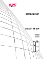
1
Installation InRow® RP CW ACRP500 ACRP501 ACRP502 This manual is available in English on the enclosed CD. Dieses Handbuch ist in Deutsch auf der beiliegenden CD-ROM verfügbar. Deze handleiding staat in het Nederlands op de bijgevoegde cd. Este manual está disponible en español en el CD-ROM adjunto. Ce manuel est disponible en français sur le CD-ROM ci-inclus. Questo manuale è disponibile in italiano nel CD-ROM allegato. 本マニュアルの日本語版は同梱の CD-ROM からご覧になれます。 Instrukcja Obsługi w jezyku polskim jest dostepna na CD. O manual em Português está disponível no CD-ROM em anexo. Данное руководство на русском языке имеется на прилагаемом компакт-диске. 您可以从包含的 CD 上获得本手册的中文版本。 您可以从付属的CD上获得本手册的中文版本。 동봉된 CD 안에 한국어 매뉴얼이 있습니다 . American Power Conversion Legal Disclaimer The information presented in this manual is not warranted by the American Power Conversion Corporation to be authoritative, error free, or complete. This publication is not meant to be a substitute for a detailed operational and site specific development plan. Therefore, American Power Conversion Corporation assumes no liability for damages, violations of codes, improper installation, system failures, or any other problems that could arise based on the use of this Publication. The information contained in this Publication is provided as is and has been prepared solely for the purpose of evaluating data center design and construction. This Publication has been compiled in good faith by American Power Conversion Corporation. However, no representation is made or warranty given, either express or implied, as to the completeness or accuracy of the information this Publication contains. IN NO EVENT SHALL AMERICAN POWER CONVERSION CORPORATION BE LIABLE FOR ANY DIRECT, INDIRECT, CONSEQUENTIAL, PUNITIVE, SPECIAL, OR INCIDENTAL DAMAGES (INCLUDING, WITHOUT LIMITATION, DAMAGES FOR LOSS OF BUSINESS, CONTRACT, REVENUE, DATA, INFORMATION, OR BUSINESS INTERRUPTION) RESULTING FROM, ARISING OUT, OR IN CONNECTION WITH THE USE OF, OR INABILITY TO USE THIS PUBLICATION OR THE CONTENT, EVEN IF AMERICAN POWER CONVERSION CORPORATION HAS BEEN EXPRESSLY ADVISED OF THE POSSIBILITY OF SUCH DAMAGES. AMERICAN POWER CONVERSION CORPORATION RESERVES THE RIGHT TO MAKE CHANGES OR UPDATES WITH RESPECT TO OR IN THE CONTENT OF THE PUBLICATION OR THE FORMAT THEREOF AT ANY TIME WITHOUT NOTICE. Copyright, intellectual, and all other proprietary rights in the content (including but not limited to software, audio, video, text, and photographs) rests with American Power Conversion Corporation or its licensors. All rights in the content not expressly granted herein are reserved. No rights of any kind are licensed or assigned or shall otherwise pass to persons accessing this information. This Publication shall not be for resale in whole or in part. Contents General Information ........................................................ 1 Overview . . . . . . . . . . . . . . . . . . . . . . . . . . . . . . . . . . . . . . . . . . . . . . . . 1 Save these instructions . . . . . . . . . . . . . . . . . . . . . . . . . . . . . . . . . . . 1 Safety symbols that may be used in this manual . . . . . . . . . . . . . . 1 Cross-reference symbol used in this manual . . . . . . . . . . . . . . . . . 1 Safety . . . . . . . . . . . . . . . . . . . . . . . . . . . . . . . . . . . . . . . . . . . . . . . . . . . 2 Inspecting the Equipment . . . . . . . . . . . . . . . . . . . . . . . . . . . . . . . . . . 3 Storing the Equipment Before Installation . . . . . . . . . . . . . . . . . . . . . 3 Moving the Equipment . . . . . . . . . . . . . . . . . . . . . . . . . . . . . . . . . . . . . 3 Moving the equipment to its final location . . . . . . . . . . . . . . . . . . . . 3 Model Identification . . . . . . . . . . . . . . . . . . . . . . . . . . . . . . . . . . . . . . . 4 Component Identification. . . . . . . . . . . . . . . . . . . . . . . . . . . . . . . . . . . 5 Install kit inventory . . . . . . . . . . . . . . . . . . . . . . . . . . . . . . . . . . . . . . . 5 Exterior components . . . . . . . . . . . . . . . . . . . . . . . . . . . . . . . . . . . . . 6 Interior components (front) . . . . . . . . . . . . . . . . . . . . . . . . . . . . . . . . 7 Electrical panel . . . . . . . . . . . . . . . . . . . . . . . . . . . . . . . . . . . . . . . . . . 9 Main controller board . . . . . . . . . . . . . . . . . . . . . . . . . . . . . . . . . . . . 10 Piping Diagrams . . . . . . . . . . . . . . . . . . . . . . . . . . . . . . . . . . . . . . . . . 11 Connections . . . . . . . . . . . . . . . . . . . . . . . . . . . . . . . . . . . . . . . . . . . . 12 Pre-Installation . . . . . . . . . . . . . . . . . . . . . . . . . . . . . . . . . . . . . . . . . . 13 Room preparation . . . . . . . . . . . . . . . . . . . . . . . . . . . . . . . . . . . . . . . 13 Air distribution . . . . . . . . . . . . . . . . . . . . . . . . . . . . . . . . . . . . . . . . . 13 Incoming power supply requirements . . . . . . . . . . . . . . . . . . . . . . 13 Service access . . . . . . . . . . . . . . . . . . . . . . . . . . . . . . . . . . . . . . . . . 14 Dimensions and Weight . . . . . . . . . . . . . . . . . . . . . . . . . . . . . . . . . . . 15 Dimensions . . . . . . . . . . . . . . . . . . . . . . . . . . . . . . . . . . . . . . . . . . . . 15 Weight . . . . . . . . . . . . . . . . . . . . . . . . . . . . . . . . . . . . . . . . . . . . . . . . 15 Piping and Power Access Locations . . . . . . . . . . . . . . . . . . . . . . . . 16 Top piping and power access locations (top view) . . . . . . . . . . . . 16 Bottom piping and power access locations (bottom view) . . . . . 17 InRow RP CW Installation i Installation...................................................................... 18 Joining the Equipment to Enclosures . . . . . . . . . . . . . . . . . . . . . . . 18 Joining to NetShelter® SX enclosures . . . . . . . . . . . . . . . . . . . . . . 18 Joining to NetShelter VX and VS enclosures . . . . . . . . . . . . . . . . . 18 Removing the Doors and Panels. . . . . . . . . . . . . . . . . . . . . . . . . . . . 19 Removing the front and rear doors . . . . . . . . . . . . . . . . . . . . . . . . . 19 Removing the side panel . . . . . . . . . . . . . . . . . . . . . . . . . . . . . . . . . 20 Installing the side panel . . . . . . . . . . . . . . . . . . . . . . . . . . . . . . . . . . 20 Removing the electrical panel cover . . . . . . . . . . . . . . . . . . . . . . . . 21 Leveling the Equipment . . . . . . . . . . . . . . . . . . . . . . . . . . . . . . . . . . . 22 Mechanical Connections . . . . . . . . . . . . . . . . . . . . . . . . . . . . . . . . . . 23 Top water piping . . . . . . . . . . . . . . . . . . . . . . . . . . . . . . . . . . . . . . . . 23 Bottom water piping . . . . . . . . . . . . . . . . . . . . . . . . . . . . . . . . . . . . . 24 Humidifier . . . . . . . . . . . . . . . . . . . . . . . . . . . . . . . . . . . . . . . . . . . . . . 25 Condensate pump . . . . . . . . . . . . . . . . . . . . . . . . . . . . . . . . . . . . . . . 26 Condensate overflow . . . . . . . . . . . . . . . . . . . . . . . . . . . . . . . . . . . . 27 Leak sensor . . . . . . . . . . . . . . . . . . . . . . . . . . . . . . . . . . . . . . . . . . . . 28 Filling and Purging the Unit. . . . . . . . . . . . . . . . . . . . . . . . . . . . . . . . 29 Chiller. . . . . . . . . . . . . . . . . . . . . . . . . . . . . . . . . . . . . . . . . . . . . . . . . . 30 InRow RP requirements . . . . . . . . . . . . . . . . . . . . . . . . . . . . . . . . . . 30 Electrical Connections . . . . . . . . . . . . . . . . . . . . . . . . . . . . . . . . . . . . 31 User interface connectors . . . . . . . . . . . . . . . . . . . . . . . . . . . . . . . . 32 Description of user interface connectors . . . . . . . . . . . . . . . . . . . . 33 Rack temperature sensors . . . . . . . . . . . . . . . . . . . . . . . . . . . . . . . . 35 Water outlet temperature sensors . . . . . . . . . . . . . . . . . . . . . . . . . . 36 Communication connections . . . . . . . . . . . . . . . . . . . . . . . . . . . . . . 37 Network port . . . . . . . . . . . . . . . . . . . . . . . . . . . . . . . . . . . . . . . . . . . 39 Power Connections . . . . . . . . . . . . . . . . . . . . . . . . . . . . . . . . . . . . . . 40 Wiring configurations . . . . . . . . . . . . . . . . . . . . . . . . . . . . . . . . . . . . 40 Top routing . . . . . . . . . . . . . . . . . . . . . . . . . . . . . . . . . . . . . . . . . . . . . 40 Bottom routing . . . . . . . . . . . . . . . . . . . . . . . . . . . . . . . . . . . . . . . . . . 40 Strain relief (ACRP502 only) . . . . . . . . . . . . . . . . . . . . . . . . . . . . . . . 41 Voltage selection . . . . . . . . . . . . . . . . . . . . . . . . . . . . . . . . . . . . . . . . 41 ii InRow RP CW Installation Warranty ......................................................................... 42 One-Year Factory Warranty . . . . . . . . . . . . . . . . . . . . . . . . . . . . . . . .42 Terms of warranty . . . . . . . . . . . . . . . . . . . . . . . . . . . . . . . . . . . . . . . 42 Non-transferable warranty . . . . . . . . . . . . . . . . . . . . . . . . . . . . . . . . 42 Exclusions . . . . . . . . . . . . . . . . . . . . . . . . . . . . . . . . . . . . . . . . . . . . . 42 Warranty claims . . . . . . . . . . . . . . . . . . . . . . . . . . . . . . . . . . . . . . . . . 43 Warranty Procedures . . . . . . . . . . . . . . . . . . . . . . . . . . . . . . . . . . . . .44 Claims . . . . . . . . . . . . . . . . . . . . . . . . . . . . . . . . . . . . . . . . . . . . . . . . . 44 Parts . . . . . . . . . . . . . . . . . . . . . . . . . . . . . . . . . . . . . . . . . . . . . . . . . . 44 InRow RP CW Installation iii General Information Overview Save these instructions This manual contains important instructions that must be followed during the installation of this equipment. Safety symbols that may be used in this manual Electrical Hazard: Indicates an electrical hazard which, if not avoided, could result in injury or death. Danger: Indicates a hazard which, if not avoided, could result in severe personal injury or substantial damage to product or other property. Warning: Indicates a hazard which, if not avoided, could result in personal injury or damage to product or other property. Heavy: Indicates a heavy load that should not be lifted without assistance. Caution: Indicates a potential hazard which, if not avoided, could result in personal injury or damage to product or other property. Tip Hazard: This equipment is easily tipped. Use extreme caution when unpacking or moving. Note: Indicates important information. Cross-reference symbol used in this manual See another section of this document or another document for more information on this subject. InRow RP CW Installation 1 Safety Note: All work should be performed by American Power Conversion (APC®) authorized personnel only. Follow all local and national codes and regulations when installing this equipment. Caution: Keep your hands, clothing, and jewelry away from moving parts. Check the equipment for foreign objects before closing the doors and starting the equipment. Heavy: The equipment is heavy. For safety purposes, at least two people must be present when moving or installing this equipment. Tip Hazard: This equipment has a high center-of-gravity. Use extreme caution when unpacking and moving. When using a forklift to move the equipment, make sure to lift only from the bottom. Electrical Hazard: Only a licensed electrician may connect the equipment to utility power. Electrical Hazard: Do not wear jewelry when working near energized components. 2 InRow RP CW Installation Inspecting the Equipment Your APC InRow RP air conditioner has been tested and inspected for quality assurance before shipment from APC. Carefully inspect both the exterior and interior of the equipment immediately upon receipt to ensure that the equipment has not been damaged during transit. Verify that all parts ordered were received as specified and that the equipment is the correct type, size and voltage. Filing a claim. If damage is identified on receipt of the equipment, note the damage on the bill of lading and file a damage claim with the shipping company. Contact APC Worldwide Customer Support at one of the numbers listed on the back page of this manual for information on how to file a claim with the shipping company. The shipping claim must be filed at the receiving end of the delivery. Note: In case of shipping damage, do not operate the equipment. Keep all packaging for inspection by the shipping company. Storing the Equipment Before Installation If the equipment will not be installed immediately, store it in a safe place, protected from the weather. Caution: Leaving the equipment uncovered and exposed to possible damage from the environment will void the factory warranty. Moving the Equipment Moving the equipment to its final location The recommended tools for moving the equipment while it is still on the pallet include the following: Pallet jack Forklift Note: The equipment can be rolled to its final location using its casters if the floor is smooth and clean. InRow RP CW Installation 3 Model Identification The model number can be found on the outside of the shipping crate and on the nameplate located inside the unit as shown. Use the table below to verify that the unit is the correct size and voltage. Model Configuration Voltage Reheat Humidifier Air Pattern ACRP500 ACRP501 ACRP502 Chilled water Chilled water Chilled water 200-240/3~/50-60 Hz 460-480/3~/60 Hz 380-415/3~/50-60 Hz Electric Electric Electric Steam canister (replaceable) Steam canister (replaceable) Steam canister (replaceable) Back to front Back to front Back to front na2600a Nameplate 4 InRow RP CW Installation Component Identification na2571a Install kit inventory Item Description Insertion adapter Quantity 2 Item Description Strain relief, metal (ACRP502 only) Wire clip 1 Humidifier PLC pipe thread, shutoff, 1/4-in NPT* (ACRP500 and ACRP501 only) 1 Wire tie - 200-mm (8 in) Humidifier PLC pipe thread, shutoff, 1/4-in BSPT ** (identified with notches on the hex head portion) (ACRP500 and ACRP502 only) 1 Wire tie - 390-mm (15.3 in) Condensate pump HFC35 pipe thread, shutoff, 3/8-in BSPT** 2 Resistor, 150-Ohm Hose adapter clamp 2 Cable tie Extension adapter Temperature sensor 3 Hose adapter 4 Reducer, 3/8-in to 1/2-in BSPT* Ring seal ® M5 x 10-mm Torx screw with 5 Reducer, 3/8-in to 1/2-in NPT** washer 5 Voltage jumper M6 x 12-mm Torx screw with washer 5 Up-connection adapter (top M6 x 10-mm self-tapping Torx screw piping adapter) M6 x 16-mm Torx screw with 5 washer * National Pipe Thread ** British Standard Pipe Thread *** Quantity varies depending on usage. See “Voltage selection” on page 38. InRow RP CW Installation Quantity 2 9 10 3 1 10 1 1 1 *** 1 5 na1824a Exterior components 6 Removable rear doors Caster Side panel lock Door handle and lock Removable side panel Display interface Adjustable leveling foot Removable front door InRow RP CW Installation na2090a Interior components (front) Electrical heater Electrical panel Fan Main feed breakers Fan guard User interface connectors Humidifier Ground wire Condensate drain pan Supply humidity sensor Condensate pump Supply temperature sensor InRow RP CW Installation 7 na2105a Interior components (rear) Chilled water coil Rear doors Chilled water control actuator Air filters Chilled water three-way valve body Return humidity sensor Flow meter Return temperature sensor Pipe chase 8 InRow RP CW Installation Electrical panel Transformers User interface connectors Main controller board Relay board Ground lug Main circuit breaker — power feed A Main circuit breaker — power feed B Automatic transfer switch (ATS) contactors ATS timers ATS transformer (ACRP501 only) ATS timer circuit breakers Fan circuit breakers Controller circuit breaker Humidifier circuit breaker Heater circuit breaker Heater contactors Humidifier contactor na2008a InRow RP CW Installation 9 Main controller board Network Management Card CRAC controller single inline memory module (SIMM) Differential Pressure SIMM Internal RS485 SIMM OPTO-isolated Input SIMM J23 connector na2082a 10 InRow RP CW Installation Piping Diagrams InRow RP Bottom piping InRow RP Return Supply Top piping Supply Return InRow RP na2572a InRow RP Flex hose or copper Circuit setter (field-installed) Copper tubing Hose end drain with cap Y-strainer with 20 mesh screen (field installed)* Isolation valve *Blow down may be installed on Y-strainer. Note: Top or bottom entry can be chosen individually for each type of connection, i.e. power, condensate drain, humidifier water supply, chilled water supply and chilled water return. Top piping configuration will have the same valves and strainers as bottom piping configuration. InRow RP CW Installation 11 Connections All connections to and from the equipment can be made through either the top or the bottom of the equipment. All connections are made with connectors so no soldering, welding, or gluing is necessary. See the following tables for information about the sizes and types of connectors. Power Connections for Power Feed A and Power Feed B Model Minimum Circuit Ampacity (MCA) Maximum Overload Protection (MOP) Full Load Amperes Rated Load Amperes (FLA) (RLA) ACRP500 42 40 ACRP501 22 20 ACRP502* 22 *Consult local and national codes for wire size, conduit requirements and overload protection. Piping Connections Type ACRP500 ACRP501 22 ACRP502 Chilled water supply Union* 1 1/2 in NPSM 1 1/2 in NPSM 1 1/2 in NPSM Chilled water return Union* 1 1/2 in NPSM 1 1/2 in NPSM 1 1/2 in NPSM Humidifier water supply Quick coupling 1/4 in NPT or BSPT 1/4 in NPT 1/4 in BSPT Condensate drain Quick coupling 1/2 in NPT or BSPT 1/2 in NPT or BSPT 1/2 in NPT or BSPT * If ring seal is damaged, use a new seal (supplied) to prevent leakage. Torque union to 20 Nm (15 lb ft) Communication Connections Type Minimum Wire Size Maximum Wire Size Rack temperature 1 RJ-45 - - - Rack temperature 2 RJ-45 - - - Rack temperature 3 RJ-45 - - - A-Link IN RJ-45 - - - A-Link OUT RJ-45 - - - Network port RJ-45 - - - Console port DB-9 Customer output, NC—Normally Closed Customer output, COM—Common Customer output, NO—Normally Open Supply GND Supply 12 VDC Supply 24 VDC Customer input + Customer input Modbus D1 Modbus D0 Modbus GND Screw connector Screw connector Screw connector Screw connector Screw connector Screw connector Screw connector Screw connector Screw connector Screw connector 2 0.2 mm (AWG 24) 2 0.2 mm (AWG 24) 0.2 mm2 0.2 mm2 (AWG 24) (AWG 24) 2 0.2 mm (AWG 24) 2 0.2 mm (AWG 24) 0.2 mm2 (AWG 24) 2 0.2 mm (AWG 24) 2 0.2 mm (AWG 24) 0.2 mm2 (AWG 24) 2 Torque - - 2 0.75 mm (AWG 18) 0.6 Nm 2 0.6 Nm 0.75 mm (AWG 18) 0.75 mm2 (AWG 18) 0.6 Nm 0.75 mm2 (AWG 18) 0.6 Nm 2 0.75 mm (AWG 18) 0.6 Nm 2 0.6 Nm 0.75 mm (AWG 18) 0.75 mm2 (AWG 18) 0.6 Nm 2 0.75 mm (AWG 18) 0.6 Nm 2 0.6 Nm 0.75 mm (AWG 18) 0.75 mm2 (AWG 18) 0.6 Nm 2 Screw connector 0.2 mm (AWG 24) 0.75 mm (AWG 18) 0.6 Nm Temperature sensor (front) RJ-45 - - - Humidity sensor (front) RJ-45 - - - Display interface RJ-45 - - - 12 InRow RP CW Installation Pre-Installation Room preparation Unacceptable operating limits Acceptable operating range 15 20 25 30 35 40 45 50 90 80 70 60 50 40 30 20 10 0 60 Ambient temperature (°C) Unacceptable operating limits Acceptable operating range 65 70 75 80 85 90 95 100 105 110 115 na2544a 90 80 70 60 50 40 30 20 10 0 10 Relative humidity (% RH) Relative humidity (% RH) During the design of the data center, consider ease of entry for the equipment, floor loading factors, and accessibility to piping and wiring. In addition, the room temperature and humidity combination should conform to the environmental operating envelope as defined in the following graphics. Ambient temperature (°F) Seal the room with a vapor barrier to minimize moisture infiltration. Polyethylene film is recommended for ceiling and wall applications. Apply rubber- or plastic-based paints to concrete walls and floors. Insulate the room to minimize the influence of exterior heat loads. Reduce fresh air to the minimum required by local and national codes and regulations. Fresh air imposes extreme load variation on the cooling equipment from summer to winter and causes increased system operating costs. Air distribution The equipment distributes air in a back-to-front discharge pattern, removing hot air from a hot aisle and discharging cooled air into a cold aisle. Note: The equipment is designed for free air discharge or for use with the Rack Air Containment System or Hot Aisle Containment System. The equipment is not intended to be connected to a duct system. Incoming power supply requirements Automatic Transfer Switch (ATS). The function of the ATS is to transfer load from feed A to feed B if the power is lost on feed A. na2252a • Feed A (Primary Power Feed) supplies power to all functions in the equipment. • Feed B (Redundant Power Feed) supplies power to all functions in the equipment. Feed A Feed B Electrical Hazard: The equipment requires three-phase electrical service. Electrical service must conform to local and national electrical codes and regulations. The equipment must be grounded. InRow RP CW Installation 13 Service access An area of minimum 900 mm (36 in) of clear floor space in front of and behind the equipment is recommended for service. All required normal maintenance can be performed from the front or back of the equipment. An area of minimum 1200 mm (48 in) of clear floor space in front of or behind the equipment is recommended to roll the equipment out of a row. Note: Check local and national codes and regulations for further service access requirements Access required to remove from row na1825a Access required to service within row Dimensions are shown in mm (in). 14 InRow RP CW Installation Dimensions and Weight na1822a Dimensions Dimensions are shown in mm (in). Weight Model Weight of equipment, packed Weight of equipment, unpacked ACRP500, ACRP501, ACRP502 462 kg (1,019 lb) 352 kg (776 lb) InRow RP CW Installation 15 Piping and Power Access Locations Top piping and power access locations (top view) 554 (21.81) 554 (21.81) 59 (2.32) 40 (1.58) 59 (2.32) 211 (8.29) 176 (6.92) FRONT—COLD AISLE Dimensions are shown in mm (in). Chilled water supply Chilled water return Trough for communication cables Power connections—dual feed Humidifier supply Condensate drain 16 InRow RP CW Installation 160 (6.3) 112 (4.4) na2274a 177 (6.97) 737 (29.02) 0 635 (24.99) 380 (14.98) 325 (12.81) 0 73 (2.86 ) 105 (4.12) 40 (1.58) REAR—HOT AISLE Bottom piping and power access locations (bottom view) 425 (16.72) 184 (7.24) 187 (7.35) 479 (18.86) 397 (15.63) 796 (31.34) 172 (6.77) 0 138 (5.43) 0 345 (13.58) 345 (13.58) REAR—HOT AISLE na2104a 156 (6.13) 115 (4.53) 141 (5.54) 176 (6.91) 57.25 (2.25) FRONT—COLD AISLE Dimensions are shown in mm (in). Chilled water supply Chilled water return Condensate overflow Communication connections—27.80 mm (1.09 in) Power connections—dual feed Condensate drain Humidifier supply InRow RP CW Installation 17 Installation Joining the Equipment to Enclosures Joining to NetShelter® SX enclosures The equipment comes with four joining brackets (two for the front and two for the rear). 1. Remove the front and rear doors. See “Removing the front and rear doors” on page 19. 2. Locate the four joining brackets. Rotate each bracket ninety degrees toward the adjoining enclosure so the bracket is parallel to the floor and install using the screws provided with the enclosure. For more information, see the Unpacking, Installation, and Customization manual for the NetShelter SX Enclosure. Joining to NetShelter VX and VS enclosures For information on joining the equipment to NetShelter VX and VS enclosures, see the installation sheet NetShelter® Enclosure Accessories Joining Kits SX to VX/VS—AR7601, AR7602. 18 InRow RP CW Installation Removing the Doors and Panels Removing the front and rear doors 1. Unlock and open the door 90 degrees. 2. Unplug the ground wires and display connection cables. na2010a 3. Lift the door up and off the hinges. Caution: When re-installing doors, reconnect the ground wires and the display interface connection cable. InRow RP CW Installation 19 na2315a Removing the side panel na2316a Installing the side panel 20 InRow RP CW Installation Removing the electrical panel cover Remove the electrical panel cover to install the main power cable. 1. Remove the five M4 screws securing the cover. 2. Remove the cover by opening it and sliding it toward the front of the equipment. na2194a Electrical Hazard: Ensure all wiring is not energized before routing cables into this equipment. Only qualified service and maintenance personnel should work on this equipment. InRow RP CW Installation 21 Leveling the Equipment Note: The leveling feet at the corners of the equipment provide a stable base if the floor is uneven, but they cannot compensate for a badly sloped surface. 1. Remove the front and rear doors. See “Removing the front and rear doors” on page 19. Note: Before removing the front door, unplug the ground wires and any other wire connections that may interfere with the removal of the doors. na1572a 2. For each leveling foot, insert a Phillips PH2 or slotted screwdriver into the screw above the leveling foot. Turn the screw clockwise to extend the leveling foot until it makes firm contact with the floor. 3. Reinstall the front and rear doors. Caution: After reinstalling the front door, reconnect the ground wire and other wire connections. Note: Use a 13-mm open-ended wrench to level the equipment without removing the doors. 22 InRow RP CW Installation Mechanical Connections Top water piping Note: The top chilled water supply pipe is supplied with the equipment and must be installed on-site. Note: You may need to remove the top panel from the equipment to gain access to the water connections. Note: New items are provided with the equipment as shown. See “Install kit inventory” on page 5. 1. Remove the air filters. 2. Loosen the two screws holding the rear condensate drain pan bracket and remove the bracket. 3. Loosen the two screws holding the air filter bracket located on the left side of the unit and remove the bracket. 4. Remove the insulation cap from the union (not shown). 6. Position the insulated chilled water supply pipe in the equipment. Mount a new gasket and connect the pipe to the union. Tighten the union to 20 Nm (14.8 ft-lb). na2027a 5. From both supply and return connections, remove the union nuts and save for reuse. Remove and discard the union end blank plates and the gaskets . 7. Insulate the joint with the provided insulation (not shown). 8. Connect the water supply pipe to the field-installed pipe using a gasket , union end , and union nut . 9. Connect the cold water return fitting to the field-installed pipe using two gaskets , union end , union nut and extension adapter . 10.Reinstall the air filter bracket . 11. Reinstall the rear condensate drain pan bracket and the air filters. na2576a 12.Reinstall the top panel, if removed. InRow RP CW Installation 23 Bottom water piping 1. Remove the insulation cap from the union (not shown). 2. Remove the union nut , and save it for reuse. Remove and discard the union end blank plate , and the ring seal . Note: New items are provided with the equipment as shown. See “Install kit inventory” on page 5. 3. Install the union nuts to fieldsupplied tubing . na2745a 4. Install new ring seals , extension adapters , and insertion adapters , as shown. 24 InRow RP CW Installation Humidifier The humidifier water supply line is routed to the unit in flexible tubing (or alternative tubing approved by local building codes) that will allow the humidifier water supply line connector to be moved approximately 25 mm (1 in) away from the equipment. This facilitates removing the equipment from a row. na2193a A factory-installed quick-connector for connecting the tubing to the equipment is supplied. See “Install kit inventory” on page 5. The quick connector has a male 1/4-in NPT or male-1/4 in BSPT to connect to a compression fitting. The quick-connector has a shut-off function, so no separate shut-off valve is necessary. na2345a The humidifier water supply line can be connected through either the top or the bottom of the equipment as shown. Male quick-connectors are positioned in both the top and the bottom of the equipment. Water pressure should be between 100 and 800 kPa (15 and 115 psi) for proper humidifier operation. Connection Connection Dirty water must be filtered through bottom through top before it is supplied to the humidifier. Water temperature must be between 1ºC and 40°C (34ºF and 104°F). Do not use softened, de-mineralized, or de-ionized water. See the manual included with the humidifier for more information about water quality, mineral content, hardness, and minimum/maximum levels for conductivity. Note: It is recommended that a solenoid water valve be installed in the humidifier supply line, connected to a leak detector. Note: Perform all piping in accordance with applicable industry guidelines as well as local and national codes and regulations. Connect the fittings to the humidifier water supply line as shown, then connect the water supply line quick-connector to the top or bottom humidifier input. Flexible tubing (field supplied and installed) Compression fitting (field supplied and installed) Quick-connector (supplied) na2536a InRow RP CW Installation 25 na2345b Condensate pump The pump is factory-wired and piped internally to the condensate drain pan and humidifier outlet. The pump can move liquid a maximum of 18 m (60 ft), which may include a maximum lift of 3.5 m (11.5 ft) at a flow rate of 87 l/hr (23 gph). For example, if your lift is 3 m (10 ft), you will have 15 m (50 ft) of usable run remaining. The pump uses an on-board condensate high level float switch wired into the equipment for alarm capabilities. Connection through top Connection through bottom Flexible tubing (field supplied and installed) 1/2-in male NPT or 1/2-in male BSPT fitting (field supplied and installed) Straight reduction (supplied) Quick connector (supplied) na2534a The condensate drain line can be connected through either the top or the bottom of the equipment using factory-installed male quick connectors and tubing approved by local building codes that will allow the drain line connector to be moved approximately 25 mm (1 in) away from the equipment. This facilitates removing the equipment from a row. Female quick connectors and reduction fittings are supplied with the equipment. Connect the fittings as shown, then connect the drain line quick connector to the top or bottom condensate pump output line. Note: Perform all piping in accordance with applicable industry guidelines as well as local and national codes and regulations. Warning: Failure to properly route the condensate pump drain line before operation could result in water damage. Warning: Do not route drain or supply lines above computer equipment, Uninterruptible Power Supply (UPS) units, Power Distribution Units (PDUs), or light fixtures. 26 InRow RP CW Installation Condensate overflow Caution: Failing to perform the following procedure may result in condensate pan overflow and possible damage to the data center. na2538a Connect the equipment condensate overflow line to an external drain using the fittings, as shown. InRow RP Hose adapter clamp (supplied) Hose adapter (supplied) 7/8-in copper tubing (field supplied and installed) InRow RP CW Installation 27 Leak sensor na1584a Install up to four optional leak sensors (AP9326) as needed. 1. Connect the leak sensor to the equipment using the plug located on the service bracket, as shown. LEA K DETEC TOR CA BLE SUC TIO N DI SCHA RG E na2266a SERV ICE 2. Position the leak sensor inside or outside the equipment. Note: Install leak sensors on a clean surface, and do not allow them to touch metal that is in an air stream. 3. Route the leak sensor to the outside through either the bottom plate or the door. na2073a 4. Secure the leak sensor wire to surfaces using cable ties and cable tie holders (provided with the leak detector). 28 InRow RP CW Installation Filling and Purging the Unit When the unit has been properly piped, begin the filling process (top piping configuration shown). Electrical Hazard: Ensure that all electrical connections are unplugged before you introduce water into the unit. 1. Open the 2-way bypass shutoff valve by turning the handle 90° clockwise.Using a 2.5-mm hex key, turn the flow control actuator to the fully open position. Top coil vent 2. Remove the cap from the top coil vent and push the vent. 3. At the water supply, open the appropriate valves to begin letting water slowly into the unit. Flow control actuator 4. Stop pushing the top coil vent when water begins slowly flowing out of the vent. Open Bypass 5. At the water supply: a. Open all valves no greater than 113 l/m (30 GPM), and allow the water supply to reach the highest possible flow to the unit for 45 seconds. na2031a b. Close the valves to a 3.8–11.4 l/m (1–3 GPM) flow for 60 seconds. Open c. Open the valves to maximum flow for another 45 seconds. d. Balance the system to provide the designed flow rate to all equipment. 2-way bypass shutoff valve InRow RP CW Installation 29 Chiller Three types of chillers can be connected to the unit: • APC size-matched chiller/thermal storage system • Building chilled water system • Existing dedicated chiller InRow RP requirements Entering water temperature 7.2–12.8°C (45–55°F) Weight of unit fully flooded with chilled water 370 kg (816 lb) Flow rate 1.2–2.5 l/s (19.0–39.6 GPM) See the chiller installation, operation, and maintenance manuals for proper installation procedures. 30 InRow RP CW Installation Electrical Connections The following electrical connections are required in the field: • Controls (user interface, Network Management Card) • Communication (A-Link, Building Management System) • Power All electrical connections must be in accordance with local and national codes and regulations. See the nameplate of the unit for voltage and current requirements. All low-voltage connections, including data and control connections, must be made with properly insulated wires. Low-voltage wiring must be insulated based on the wiring with which it is routed. Wiring does not require 300-V insulation if it is separated from line voltage wiring. However, it will need 600-V insulation if it is wired in the same cable tray as 480-Vac wiring. Electrical Hazard: Potentially dangerous and lethal voltages exist within this unit. More than one disconnect switch may be required to energize or de-energize this equipment. Observe all cautions and warnings. Failure to do so could result in serious injury or death. Only qualified service and maintenance personnel may work on this equipment. Warning: Before making any electrical connections, make sure that the unit is turned off and locked-out. Lockout/tagout represents safety procedures that remove access to a device and physically labels the device as intentionally out of service. Electrical Hazard: Three-phase (plus ground) electrical service is required. Electrical service must conform to local and national electrical codes and regulations. The equipment must be grounded. Check the nameplate for correct Full Load Current and Minimum Disconnect Size. InRow RP CW Installation 31 User interface connectors Rack inlet temperature sensors 1, 2, 3 A-Link IN A-Link OUT Network port Console port Customer output, NC (Normally Closed) Customer output, COM (Common) Customer output, NO (Normally Open) Supply GND (Ground) Supply 12 Vdc (current limit: 20 mA) Supply 24 Vdc (current limit: 20 mA) Remote shutdown+ (12–30 Vac/Vdc, 24 Vdc @ 11 mA) Remote shutdown- Modbus D1 (RXTX+) Modbus D0 (RXTX–) Modbus GND Supply air temperature sensor (front) Supply air humidity sensor (front) Display interface na2009a Note: For a top installation, route control wiring through the wire channel located at the top left hand corner just above the user interface connectors. 32 For a bottom installation, route the control wiring to the customer access hole in the bottom of the equipment through wire clamps from the interface connectors. Then, route the wiring down along the electrical panel and secure with wire clamps. InRow RP CW Installation Description of user interface connectors Item Description Rack temperature sensors 1, 2, 3 Three temperature sensors which must be installed on the cold aisle side of the server racks. See “Rack temperature sensors” on page 35. A-Link IN A-Link OUT In and out connections for A-Link. The terminators supplied with the equipment must be plugged into the first A-link port and the final A-Link port for the system. Network port 10/100 Base-T Network port. Connects the equipment to the network; Status and Link LEDs indicate network traffic. • Status LED—blinks orange and green at startup; indicates the status of the network connection (solid green—IP address established; blinking green—attempting to obtain an IP address). • Link LED—blinks to indicate network traffic (green—operating at 10 mbps; orange— operating at 100 mbps). Console port RS-232 communication port used for local service access to the equipment. Use configuration cable (APC part number 9400103) to connect to this port. Customer output, Normally Closed (NC) Customer output, Common (COM) Customer-configurable output relay which can be activated for all types of alarms or critical alarms. The relay can be connected to external equipment using 30 Vac/dc, 2 A. Customer output, Normally Open (NO) Supply GND Can be used for customer input and output interface. Supply 12 Vdc Can be used for customer input and output interface. Current limit is 20 mA. Supply 24 Vdc Can be used for customer input and output interface. Current limit is 20 mA. Remote shutdown+ Used for remote shutdown of the InRow RP. Voltage is applied from the internal power supply or by using an external power supply. Remote shutdown- Ground connection point for remote shutdown supply source. InRow RP CW Installation 33 34 Item Description Modbus D1 (RXTX+) Modbus D0 (RXTX–) Modbus GND Connections for Building Management System. Wire a 150 Ohm terminator resistor (supplied) into the final InRow RP, between Modbus D0 and Modbus D1. Supply air temperature sensor (front) Temperature sensor installed on the front of the equipment. Supply air humidity sensor (front) Humidity sensor installed on the front of the equipment. Display interface Connection for the display interface installed on the front door of the equipment. InRow RP CW Installation Rack temperature sensors The rack temperature sensors control the unit airflow and ensure adequate supply of cooling air to the server racks in the data center. gen0744a The unit is supplied with three external rack temperature sensors. These sensors, along with wire clamps and wire clips, are included in the install kit supplied with the unit in a separate box. Installing the rack temperature sensors 1. Insert the rack temperature sensor connector in the temperature sensor port at the user interface. See “User interface connectors” on page 32. a. For a top installation, push the rack temperature sensor through the wire channel located at the top of the equipment in the left hand side just above the user interface connectors. Temperature sensor Wire clip 2. Route the sensor through either the top or the bottom of the adjacent server rack. 3. Secure the temperature sensor cable to the front door of the adjacent server rack at multiple locations using the provided wire clips as shown. gen0767a b. For a bottom installation, route the sensor through the wire clamps along the electrical panel and then push the sensor through the customer access hole in the bottom of the equipment. Note: Remote temperature sensors must be installed for proper operation. The sensors must be installed where lack of sufficient cooling air is most likely. The optimum position of the rack temperature sensors will vary from installation to installation. Servers most likely to have insufficient or inadequately cooled cooling air due to the recirculation of hot air from the hot aisle include: a. Servers positioned at the top of a rack. b. Servers positioned at any height in the last rack at an open end of a row. c. Servers positioned behind flow-impairing obstacles such as building elements. d. Servers positioned in a bank of high-density racks. e. Servers positioned next to racks with Air Removal Units (ARU). f. Servers positioned very far from the equipment. g. Servers positioned very close to the equipment. InRow RP CW Installation 35 Water outlet temperature sensors The unit is delivered with top connection as the default configuration, i.e. the wire with a green wire tie is positioned in connector J23 (marked with green) on the main board. If the configuration is changed from top to bottom, switch the wire already positioned in the connector J23 with the wire labeled with a green and a white wire tie. This wire is part of the wire harness inside the electrical panel. 36 Top connection: Wire with green wire tie in J23 J23 na2263a There are two water outlet temperature sensors, one for top connection and one for bottom connection. These sensors are wired to the main board on the electrical panel. See “Main controller board” on page 10. Bottom connection: Wire with green and white wire ties in J23 InRow RP CW Installation Communication connections A-Link connections. The A-Link bus connection allows communication between equipment. Only one InRow RP needs to be defined through the display. The numbering of the other equipment (up to a maximum of twelve) will take place automatically. To enable the equipment to work as a group, link the units using CAT-5 cables with RJ-45 connectors as shown. Terminators must be inserted into the A-Link ports at the first and last InRow RP. The maximum wire length for the entire group may not exceed 1000 m (3,280 ft). Second InRow RP Last InRow RP na0733a First InRow RP A-Link IN (with provided RJ-45 terminator) InRow A-Link cable (CAT-5 ethernet cable) A-Link IN A-Link OUT (with provided RJ-45 terminator) A-Link out InRow RP CW Installation 37 Building Management System (BMS). The Modbus interface allows each InRow RP to communicate with the BMS. Use a three-wire cable to connect each InRow RP in turn. Wire a terminator resistor (150 Ohm, 1/4 W) into the Modbus master and the final InRow RP between Modbus D0 and Modbus D1. This terminator is included in the installation kit (see “Install kit inventory” on page 5). Each InRow RP has a three-wire Modbus terminal on the user interface. A connector with screw terminals is used to allow wiring to be attached. See “User interface connectors” on page 32 for specific layout of the user interface. For information on setup of Modbus parameters, see the InRow RP Operation manual. First InRow RP InRow RP # 2 Last InRow RP na1766a Modbus master Termination resistor (provided) Modbus cable (RS-485) 38 InRow RP CW Installation Network port The Network port allows communication from the InRow RP to the network. First InRow RP Second InRow RP Last InRow RP Switch/Hub Network port LAN cable (10/100 Base-T) InRow RP CW Installation 39 Power Connections Wiring configurations Electrical Hazard: Only a licensed electrician may connect the equipment to utility power. Route incoming power from the PDU to the electrical panel located in the left side of the equipment. Power can be routed either through the top or the bottom. Top routing 1. Roll the unit into the row. 2. Remove the electrical panel cover. See “Removing the electrical panel cover” on page 21. 3. Locate the power connection plate in the top of the unit. See “Top piping and power access locations (top view)” on page 16. 4. Loosen the screw securing the connection plate, and remove the plate. 5. Attach the conduit connectors using the pilot hole in the connection plate. 6. Route the cabling to the main breakers as shown. 7. Connect feed A and B power wiring to the tops of the two main circuit breakers using the torque specified on the breakers. Connect the phases of the two power feeds as marked next to the terminals. 8. Connect the ground wires to the ground terminal block located above the main circuit breakers. 9. Reinstall the connection plate and the electrical panel cover. Bottom routing 1. Roll the equipment into the row. 2. Remove the electrical panel cover. See “Removing the electrical panel cover” on page 21. 3. Locate the power connection plate in the bottom of the unit. See “Bottom piping and power access locations (bottom view)” on page 17. 4. Loosen the screw securing the connection plate, and remove the plate. 5. Attach the conduit connectors using the two pilot holes in the connection plate. 6. Route the cabling to the main breakers as shown. 7. Fasten the cabling inside the unit with the provided wire ties. 9. Connect the ground wires to the ground terminal block located just above the main circuit breakers. 10.Reinstall the connection plate and the electrical panel cover. 40 InRow RP CW Installation na2328a 8. Connect feed A and feed B power wiring to the tops of the two main circuit breakers using the torque specified on the breakers. Connect the phases of the two power feeds as marked next to the terminals. Strain relief (ACRP502 only) Adjustable metal strain reliefs are provided. See “Install kit inventory” on page 5. 1. Hook one strain relief into a pair of slots in each of the two locations shown. 2. Route the electrical cable up from the bottom of the equipment, passing through the strain reliefs. 3. Tighten the screws on the strain reliefs to capture the electrical cable, taking the weight off of the inner conductors. na2542a 4. Continue connecting electrical wiring to the circuit breaker. Voltage selection na2540a Your equipment can operate at various supply voltages, provided the proper voltage jumpers are connected to the input transformers. Read the part number on the jumpers connected at the factory and compare that number to the table below. If the correct jumpers for your input voltage are not connected, remove them and connect the proper jumper. Jumper Connections Transformer B connected to J51 () Transformer A connected to J50 () SKU ACRP500 ACRP501 ACRP502 Input Voltage Use Jumper Part Number 208 (50/60 Hz) 0W2540 (default) 230 (50/60 Hz) 0W2541 460 (60 Hz) 0W2545 480 (60 Hz) 0W2546 (default) 380 (50/60 Hz) 0W2542 400 (50/60 Hz) 0W2543 (default) 415 (50/60 Hz) 0W2544 InRow RP CW Installation 41 Warranty One-Year Factory Warranty The limited warranty provided by American Power Conversion (APC®) in this Statement of Limited Factory Warranty applies only to products you purchase for your commercial or industrial use in the ordinary course of your business. Terms of warranty American Power Conversion warrants its products to be free from defects in materials and workmanship for a period of one year from the date of purchase. The obligation of APC under this warranty is limited to repairing or replacing, at its sole discretion, any such defective products. This warranty does not apply to equipment that has been damaged by accident, negligence or misapplication or has been altered or modified in any way. Repair or replacement of a defective product or part thereof does not extend the original warranty period. Any parts furnished under this warranty may be new or factoryremanufactured. Non-transferable warranty This warranty extends only to the original purchaser who must have properly registered the product. The product may be registered at the APC Web site, www.apc.com. Exclusions APC shall not be liable under the warranty if its testing and examination disclose that the alleged defect in the product does not exist or was caused by end user’s or any third person’s misuse, negligence, improper installation or testing. Further, APC shall not be liable under the warranty for unauthorized attempts to repair or modify wrong or inadequate electrical voltage or connection, inappropriate on-site operation conditions, corrosive atmosphere, repair, installation, start-up by non-APC designated personnel, a change in location or operating use, exposure to the elements, Acts of God, fire, theft, or installation contrary to APC recommendations or specifications or in any event if the APC serial number has been altered, defaced, or removed, or any other cause beyond the range of the intended use. THERE ARE NO WARRANTIES, EXPRESS OR IMPLIED, BY OPERATION OF LAW OR OTHERWISE, OF PRODUCTS SOLD, SERVICED OR FURNISHED UNDER THIS AGREEMENT OR IN CONNECTION HEREWITH. APC DISCLAIMS ALL IMPLIED WARRANTIES OF MERCHANTABILITY, SATISFACTION AND FITNESS FOR A PARTICULAR PURPOSE. APC EXPRESS WARRANTIES WILL NOT BE ENLARGED, DIMINISHED, OR AFFECTED BY AND NO OBLIGATION OR LIABILITY WILL ARISE OUT OF, APC RENDERING OF TECHNICAL OR OTHER ADVICE OR SERVICE IN CONNECTION WITH THE PRODUCTS. THE FOREGOING WARRANTIES AND REMEDIES ARE EXCLUSIVE AND IN LIEU OF ALL OTHER WARRANTIES AND REMEDIES. THE WARRANTIES SET FORTH ABOVE CONSTITUTE APC’S SOLE LIABILITY AND PURCHASER’S EXCLUSIVE REMEDY FOR ANY BREACH OF SUCH WARRANTIES. APC WARRANTIES EXTEND ONLY TO PURCHASER AND ARE NOT EXTENDED TO ANY THIRD PARTIES. 42 InRow RP CW Installation IN NO EVENT SHALL APC, ITS OFFICERS, DIRECTORS, AFFILIATES OR EMPLOYEES BE LIABLE FOR ANY FORM OF INDIRECT, SPECIAL, CONSEQUENTIAL OR PUNITIVE DAMAGES, ARISING OUT OF THE USE, SERVICE OR INSTALLATION, OF THE PRODUCTS, WHETHER SUCH DAMAGES ARISE IN CONTRACT OR TORT, IRRESPECTIVE OF FAULT, NEGLIGENCE OR STRICT LIABILITY OR WHETHER APC HAS BEEN ADVISED IN ADVANCE OF THE POSSIBILITY OF SUCH DAMAGES. SPECIFICALLY, APC IS NOT LIABLE FOR ANY COSTS, SUCH AS LOST PROFITS OR REVENUE, LOSS OF EQUIPMENT, LOSS OF USE OF EQUIPMENT, LOSS OF SOFTWARE, LOSS OF DATA, COSTS OF SUBSTITUENTS, CLAIMS BY THIRD PARTIES, OR OTHERWISE. NO SALESMAN, EMPLOYEE OR AGENT OF APC IS AUTHORIZED TO ADD TO OR VARY THE TERMS OF THIS WARRANTY. WARRANTY TERMS MAY BE MODIFIED, IF AT ALL, ONLY IN WRITING SIGNED BY AN APC OFFICER AND LEGAL DEPARTMENT. Warranty claims Customers with warranty claims issues may access the APC customer support network through the Support page of the APC Web site, www.apc.com/support. Select your country from the country selection pull-down menu at the top of the Web page. Select the Support tab to obtain contact information for customer support in your region. InRow RP CW Installation 43 Warranty Procedures Claims To obtain service under the warranty, contact APC Customer Support (see the back cover of this manual for contact information). You will need the model number of the Product, the serial number, and the date purchased. A technician will also ask you to describe the problem. If it is determined that the Product will need to be returned to APC, you must obtain a returned material authorization (RMA) number from APC Customer Support. Products that must be returned must have the RMA number marked on the outside of the package and must be returned with transportation charges prepaid. If it is determined by APC Customer Support that on-site repair of the Product is allowed, APC will arrange to have APC authorized service personnel dispatched to the Product location for repair or replacement, at the discretion of APC. Parts • APC warrants the parts of their systems for 1 year from the date of commissioning or 18 months from the ship date. This warranty only covers the cost of the part and not the labor for installation. • Calls for warranty parts requests need to have specific unit information (serial number, model number, job number) to allow proper identification and processing of the warranty part transaction. • A purchase order may be required to issue any warranty parts. An invoice will be sent once the parts are shipped to the field. You have 30 days to return the defective parts to APC. After 30 days, the warranty invoice will be outstanding, and payment of the invoice will be expected in full. • Return authorization documentation will be sent with the replacement part. This documentation must be sent back with the defective part to APC for proper identification of the warranty return. Mark the warranty return number on the outside of the package. • After the part has been received at APC, we will determine the status of the credit based on the findings of the returned part. Parts that are damaged from lack of maintenance, misapplication, improper installation, shipping damage, or acts of man/nature will not be covered under the parts warranty. • Any warranty parts request received before 1:00 PM EST will be shipped same-day standard ground delivery. Any costs associated with Next Day or Airfreight will be the responsibility of the party requesting the part. • Return freight of warranty parts to APC is the responsibility of the party returning the part. 44 InRow RP CW Installation Radio Frequency Interference Changes or modifications to this unit not expressly approved by the party responsible for compliance could void the user’s authority to operate this equipment. USA—FCC This equipment has been tested and found to comply with the limits for a Class A digital device, pursuant to part 15 of the FCC Rules. These limits are designed to provide reasonable protection against harmful interference when the equipment is operated in a commercial environment. This equipment generates, uses, and can radiate radio frequency energy and, if not installed and used in accordance with this user manual, may cause harmful interference to radio communications. Operation of this equipment in a residential area is likely to cause harmful interference. The user will bear sole responsibility for correcting such interference. Canada—ICES This Class A digital apparatus complies with Canadian ICES-003. Cet appareil numérique de la classe A est conforme à la norme NMB-003 du Canada. Japan—VCCI This is a Class A product based on the standard of the Voluntary Control Council for Interference by Information Technology Equipment (VCCI). If this equipment is used in a domestic environment, radio disturbance may occur, in which case, the user may be required to take corrective actions. この装置は、情報処理装置等電波障害自主規制協議会(VCCI)の基準 に基づくクラス A 情報技術装置です。この装置を家庭環境で使用すると、電波 妨害を引き起こすことがあります。この場合には、使用者が適切な対策を講ず るように要求されることがあります。 Taiwan—BSMI 警告使用者 : 這是甲類的資訊產品 , 在居住的 環境中使用時 , 可能會造成射頻 干擾 , 在這種情況下 , 使用者會 被要求採取某些適當的對策。 APC Worldwide Customer Support Customer support for this or any other APC product is available at no charge in any of the following ways: • Visit the APC Web site to access documents in the APC Knowledge Base and to submit customer support requests. – www.apc.com (Corporate Headquarters) Connect to localized APC Web sites for specific countries, each of which provides customer support information. – www.apc.com/support/ Global support searching APC Knowledge Base and using e-support. • Contact an APC Customer Support center by telephone or e-mail. – Regional centers Direct InfraStruXure Customer Support Line (1)(877)537-0607 (toll free) APC headquarters U.S., (1)(800)800-4272 Canada (toll free) Latin America (1)(401)789-5735 (USA) Europe, Middle East, Africa (353)(91)702000 (Ireland) Western Europe (including Scandinavia) +800 0272 0272 Japan (0) 36402-2001 Australia 1(800) 652 725 (toll free) New Zealand 0 (800) 333 373 (toll free) – Local, country-specific centers: go to www.apc.com/support/contact for contact information. Contact the APC representative or other distributor from whom you purchased your APC product for information on how to obtain local customer support. To obtain a repair authorization number for a Cooling Solutions product, call Cooling Solutions Technical Service between 8:00 A.M. and 5:00 P.M. Eastern time, Monday through Friday: • Phone: (1)(888)695-6500 (USA and Canada only, toll free) • Fax: (1)(401)788-2691 Entire contents copyright 2008 American Power Conversion Corporation. All rights reserved. Reproduction in whole or in part without permission is prohibited. APC, the APC logo, NetShelter, and InRow are trademarks of American Power Conversion Corporation. All other trademarks, product names, and corporate names are the property of their respective owners and are used for informational purposes only. 990-2710B-001 *990-2710B-001* 04/2008