1
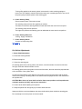
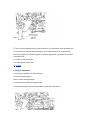
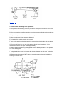
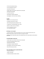
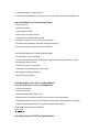
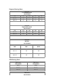
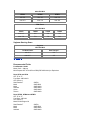
3961 Miraloma Avenue
Anaheim, CA 92806
Toll Free 800.326.6992
Local 714.572.3656
Fax 714.572.0282
Operation
1. Manual Steering Gear.
A mechanical means of steering control.
The steering wheel turns a shaft attached to the input shaft, which turns a spiral worm gear.
The spiral worm gear turns an output shaft, which horizontally moves the pitman arm, drag
link and steering arms, turning the front wheels.
2. Manual Steering Gear with Valve-in-Linkage Assist.
A mechanical means of steering with a hydraulic control valve and a cylinder.
The hydraulic control valve is installed in the vehicle drag link.
Turning effort applied to the steering wheel actuates the valve, which, in turn, directs
hydraulic fluid from the pump to the power cylinder located in the steering linkage.
3. Semi-Integral Steering Gear.
A mechanical means of steering with a hydraulic control valve and a cylinder.
The hydraulic control valve is attached to the steering gear.
Ross Hydrapower Steering Gear
Turning effort applied to the steering wheel overcomes the valve centering spring and
hydraulic reaction which moves the valve spool, restricting the return port. This increases
the flow to one of the cylinder ports, actuating one end of the piston giving hydraulic power
to the linkage where the cylinder is attached.
Saginaw Steering Gear
Turning effort applied to the steering wheel turns the input shaft attached to a torsion bar.
When receiving resistance from the wheels the torsion bar is twisted actuating the control
valve. This directs fluid to one end of the piston in the cylinder giving hydraulic power to the
linkage.
4. Integral Steering Gear.
A mechanical means of steering with a hydraulic control valve and a cylinder combined into
one component.
Turning effort applied to the steering wheel overcomes the valve centering springs or
torsion bar. The hydraulic reaction restricts the return port, increasing the flow to one end of
the piston giving hydraulic power to the steering gear.
5. Power Steering Pump.
Pressure means work. Flow means speed.
The steering pump produces flow (gallons per minute).
The faster or slower the steering wheels turn will determine how much fluid is required.
The steering pump relieves pressure.
The higher the pressure the steering gear can withstand the more work it can perform.
6. Power Steering Reservoir.
Cooling, supply, and filtration
7. Power Steering Hoses.
A means of transporting fluid
Top of page
On-Vehicle Adjustments
1. Sector Shaft Adjustment:
A. Center the steering wheels.
B. Remove drag link.
C. Center the steering gear.
On steering gears with no timing mark on the sector, count the number of turns from full left to
full right, come back half the number of turns.
On steering gears with a timing mark on the end of the sector, the mark should be perpendicular
to the centerline of the cylinder bore.
On the Ross TAS steering gears align the timing mark on the end of the sector with the timing
mark on the housing. The timing mark on the sector should be perpendicular to the centerline of
the cylinder bore.
CAUTION: More than one input shaft revolution from center position could reposition the
automatic poppets and they may become inoperative.
D. Loosen sector shaft adjusting screw jamnut.
E. Grasp the pitman arm and gently try to rotate it back and forth.
Attempt to feel the movement between the sector shaft and the piston inside the steering gear.
Do not attempt to move the piston or the worm shaft.
Attempt to feel the movement between the sector shaft and the piston inside the steering gear.
Do not attempt to move the piston or the worm shaft.
F. Turn the sector adjusting screw counter-clockwise if no movement is felt in the pitman arm.
G. Turn the sector adjusting screw clockwise until no movement is felt in the pitman arm.
Do not over-adjust or over-tighten, tighter is not better, adjustment is complete as soon as no
movement is felt.
H. Torque jam-nut 40-45 ft lbs.
I. Recheck pitman arm for lash.
Top of page
2. Drag-link adjustment:
A. Remove the drag link from the pitman arm.
B. Center the steering gear.
Refer to sector shaft adjustment
C. Set the front steering tires straight ahead.
D. Adjust the drag-link to the pitman arm without moving the pitman arm.
Top of page
3. Pressure Relief / Unloading Valve Adjustment:
A. The pressure relief/unloading valves are provided to reduce pressure when the wheels have
reached the end of turn.
B. The valves keep the pump from operating at maximum pressure relief when the steer wheels
reach their steering limits.
C. Adjust axle stops according to the manufacturer's specs
D. Start the engine and allow it operate at idle speed.
E. Full weight of the vehicle must be on the wheels.
F. Turn steering wheel one direction until a high pressure hiss is heard or the axle stop makes
contact.
G. Turn the relief valve in or out until a high-pressure hiss is heard when there is 1/8-inch
clearance between the axle stops. (See diagram below).
H. Repeat the procedure steering in the opposite direction adjusting the valve on the opposite
end of the steering gear.
I. Turning the adjusting screws in increases the clearance between the axle stops. Turning the
adjusting screws out decreases the clearance.
On Sheppard steering gears DO NOT screw the adjusting screws out beyond flush with the
housing or a leak will occur.
Top of page
4. Ross TAS Automatic Poppet Valve Adjustment:
For installation of new and remanufactured steering gears only.
1. Lift front wheels off the ground.
2. Start engine and let operate at idle. All linkage must be connected at this point.
3. Steer wheels to full travel in one direction until the linkage firmly bottoms against the axle stop.
(Maximum torque 30lbs. of rim pull on a 20inch wheel for this step).
4. Steer wheels to the other direction-repeating step 3.
5. Set front wheels on the ground rechecking travel.
Top of page
5. Ross TAS manual readjustment of poppet valves:
(Two people will be required for this procedure.)
A. Set axle stops to vehicle manufacture's wheelcut or clearance specifications.
B. Start the engine and let run for 5 to 10 minutes to allow hydraulic fluid to warm up. Turn off
engine
C. If the steering gear is equipped with a fixed poppet bolt and washer at the lower end of the
housing, it must be replaced with an adjusting poppet screw and sealing nut. (The adjusting
screw will have to be purchased separately, part #021407X1 for most gears).
D. Screw the sealing nut onto the drive screw until it is flush with the end of the adjusting screw.
E. Screw the adjusting screw in until the sealing nut is firmly against the housing. Tighten the
sealing nut.
F. Lift front wheels off the ground and check fluid levels.
G. Observe the end of the sector shaft for the direction of travel (see page 6).
H. Start the engine and let it run at idle.
I. Note which timing mark is nearest to the housing piston bore.
J. Turn the steering wheel in the direction that makes the timing mark move toward the adjusting
screw at the end of the housing. Turn in this direction until the axle stop contact is made.
K. Pull hard on the steering wheel (about 40lbs. of rim pull on a 20-inch diameter wheel) after the
axle stop contact is made.
L. Turn the steering wheel in the opposite direction until the other side axle stop is contacted.
M. Pull hard on the steering wheel (about 40lbs. of rim pull on a 20-inch diameter wheel)
N. Release the steering wheel and shut off the engine.
O. Loosen sealing nut and back out adjusting screw 1 inch past the end of the sealing nut.
P. Tighten the sealing nut against the housing.
Q. Start engine and let engine idle.
R. Turn the steering wheel in the opposite direction (timing mark toward adjusting screw) until
the axle stop contact is made.
S. Hold the steering wheel in this position for no more than 10 seconds and release as many
times as necessary while completing the next two steps.
T. Loosen the jam nut and hold it in place with a wrench.
U. Turn in the adjusting screw in with an allen wrench using finger pressure only (don't use a
ratchet) until the allen wrench stops turning. Do not attempt to turn in any farther. Caution:
Applying pressure to the steering wheel at the end of travel for more than 10 seconds may
damage the steering pump.
V. Back out the adjusting screw 3-1/4 of a turn and tighten the sealing nut.
W. The adjusting screw must not exceed 1-1/16 inch beyond the sealing nut for proper thread
engagement.
X. Torque adjusting screw sealing nut 35-ft lbs.
Top of page
TRW Input Shaft Seal Replacement for TAS Gears.
1. Disconnect the return line from the steering. Plug off the return line and cap the return port of
the gear with a high pressure fitting.
2. Remove the steering column from the input shaft of the steering gear.
3. Remove the dirt and water seal from the steering gear.
4. Wipe out the grease to remove the spiral retaining ring. Insert a screwdriver into the notch
formed in the end of the ring. Be careful not to scratch the bore with the screwdriver.
5. Slip the steering column back onto the input shaft and install the pinch bolt, do not tighten.
6. Wrap or tie a shop towel around the input shaft area and place a drip pan under the vehicle to
catch the oil.
7. Check the fluid level and add as necessary.
8. Momentarily turn the starter without starting the engine (quickly turn off the engine if it starts).
9. Remove the shop towel, check to be sure the seal was forced out.
10. Remove the steering column and remove the input shaft seal.
11. Check for and remove any seal fragments left in the seal area.
12. Apply clean grease on the inside diameter of the new input shaft seal.
13. With the small diameter of the input shaft seal installer against the seal, tap the tool until the
tool shoulder is squarely against the valve housing (seal installer tool will have to be purchased
separately). CAUTION: If a socket is used to install the seal you will not be able to control the
depth possibly causing a leak.
14. Insert the new retaining ring into the groove.
15. Apply grease around the input shaft seal and apply grease to the correct size dirt and water
seal. Install the seal over the input shaft and seat it against the valve housing.
16. Reconnect the steering column to the input shaft and tighten the pinch bolt to the proper
torque.
17. Remove return line plug and cap and reconnect the return line to the steering gear.
18. Check steering fluid level and air bleed the steering system.
Top of page
Flushing the Steering System:
1. Lift front wheels off the ground.
2. Disconnect the return line from the reservoir. Put in a container and plug off the reservoir.
3. Disengage the ignition.
4. Engage starter while turning wheels from left to right.
5. Do not allow the reservoir to run out of fluid.
6. Reattach return line to reservoir.
7. Recheck fluid level.
Top of page
Filling and Air Bleeding the System:
1. Fill the reservoir nearly full, start and run engine for 10 seconds.
2. Check and refill the reservoir.
3. Repeat this at least three times. Do not allow reservoir to run out of fluid. This may induce air
into the system.
4. Start the engine and let idle for two minutes. Then turn off the engine. Recheck the fluid level.
5. Lift the front wheels off the ground.
6. Start the engine and let idle.
7. Steer front wheels full left then full right to complete bleeding.
The relief/unloading valve adjustment should be implemented before completing this process.
Check if the gear is mounted in an inverted position with a manual bleed screw.
8. If equipped with a manual bleed screw turn full left to full right several times.
9. Loosen manual bleed screw one turn, allowing fluid to bleed out.
10. Close bleed screw after only clear fluid is bleeding out.
11. Repeat the last three steps to be sure only clear fluid is bleeding out.
Top of page
Pressure and Flow Testing the Steering System
Pump Testing:
1. Make necessary gauge/meter connections on pressure line between pump and steering gear.
2. Start engine and check fluid level assuring that oil flow is in proper direction through the flow
meter.
3. Place thermometer in reservoir.
4. Steer from lock to lock several times to allow system to warm up. (140º to 160º F.)
5. At idle speed slowly turn the shutoff valve until closed, reading the pressure at which the
pressure relief valve opens. Quickly open the valve to avoid heat build up or possible damage.
Caution: If the pressure rises rapidly or is uncontrollable do not completely close the valve.
Damage may occur or hoses may rupture.
6. Read the flow at idle and at 1500 rpm in a stationary position. (The flow must not be above the
maximum flow specification).
7. At idle turn the steering wheel full left and full right observing the flow rate. (The flow must not
drop below the minimum Gallons Per Minute flow specification while turning with a load on the
front axle).
8. Normal backpressure will be 50 to 75 PSI with the engine idling and the steering wheel
stationary. Check at normal operating temperature.
Top of page
Steering Gear Internal Leakage Test:
1. With engine running steer the vehicle to the left.
2. Place a one inch spacer block long enough to keep fingers clear, between the axle and axle
stop (to prevent the operation of the unloading/poppet valves).
3. Apply 20 lbs. to the rim of the steering wheel to be sure the control valve is fully closed.
4. The pressure relief valve should read pump relief pressure as noted in the pump test.
5. The flow should range from 0 to 1 GPM.
6. If the flow exceeds 1gpm check for an auxiliary gear or cylinder, disconnect and repeat the
test.
7. Repeat the test for the opposite direction of turn.
Top of page
Steering Column Maintenance:
The steering column is probably the most overlooked area in steering system maintenance. Most
of the causes of the steering column problems are related to improper lubrication. Some of the
common symptoms are as follows:
1. Vehicle will continue to steer by itself after an initial turn is started.
2. Vehicle will wander
3. Vehicle will stay steering wherever the steering wheel is put.
4. Steering wheel will lock up or hang up every quarter of a turn.
Top of page
Steering Column Checks:
Do these steps with the vehicle on the ground and engine off.
1. Pull around the steering wheel about 4 to 5 inches the steering wheel must spring back.
2. If the steering wheel will not spring back install an inch pound torque wrench on the column
nut at the steering wheel. Record the readings from the torque wrench steering full left to full
right.
3. If the torque wrench fluctuates more than 15 inch pounds from right to left you have a u-joint
or timing problem.
A. One greaseless u-joint cap or improperly installed cap may cause this problem. The entire
steering column may have to be removed to find this problem.
B. The u-joints are designed to operate best at a maximum of 25 degrees between the drive
shaft and the driven shaft.
C. If the steering column is not timed properly it will also cause this problem. On most steering
columns there are arrows to show the proper phasing. When no arrows are present, make sure
the column yokes are in line to maintain proper timing.
D. If proper timing still has not been accomplished rotate the two piece shaft one spline at a time
until the torque reading is the same through the rotation of the wheel.
4. If a problem still exists the next step is to remove the steering column yoke off the steering
gear.
5. Install an inch pound torque wrench on the gear, If the readings between the gear and the
steering wheel, is more than 10inch pounds you still have a steering column problem.
A. Check the slip-yoke to be sure it is not frozen tight and that the u-joints are moving properly.
B. Check the steering column slip-joint making sure it has movement within itself.
C. Check the steering wheel, to see that it is not tight into the steering column housing.
Top of page
POSSIBLE STEERING PROBLEMS AND CAUSES
ROAD WANDER
- Tire pressure incorrect or unequal left to right.
- Components in steering linkage loose or worn (Steering wheel to road wheel).
- Wheel bearings improperly adjusted or worn.
- Front end alignment out of specification.
- Dry fifth wheel or poor finish on fifth wheel or trailer plate.
- Steering gear mounting bolts loose on frame.
- Steering gear improperly adjusted.
- Looseness in rear axle assemblies or trailer bogies.
NO RECOVERY
- Tire pressure low
- Front end components binding
- Front end alignment incorrect
- Tight front axle king pins
- Looseness in rear axle assemblies or trailer bogies.
NO RECOVERY
- Tire pressure low
- Front end components binding
- Front end alignment incorrect
- Tight front axle king pins
- Dry fifth wheel or poor finish on fifth wheel or trailer plate
- Steering column binding
- Pump flow insufficient
- Steering gear improperly adjusted
- Steering gear control valve sleeve sticking
SHIMMY
- Badly worn or unevenly worn tires
- Improperly mounted tire or wheel
- Wheel bearings improperly adjusted or worn
- Components in steering linkage loose or worn
- Wheels or brake drums out of balance
- Front end alignment incorrect
- Air in the hydraulic system
EXTERNAL OIL LEAKAGE
- Finding the location of leak may be difficult, since oil may run away from leak source, the
fittings, hoses, pumps, or gear to a low point on the gear or chassis.
- A leak from the vent plug at the side cover indicates failure of the sector shaft oil seal inside the
side cover.
OVERSTEERING OR DARTING
- Dry fifth wheel or poor finish on fifth wheel or trailer plate
- Front end components binding or loose
- Steering column binding
- Steering gear improperly adjusted
- Steering gear control valve sleeve sticking
- Rear axle mounts (rear steer)
HIGH STEERING EFFORT IN ONE DIRECTION
- Unequal tire pressure
- Vehicle overloaded
- Inadequate hydraulic system pressure
- Excessive internal leakage in one direction of turn only (verify with internal (leakage test)
HIGH STEERING EFFORT IN BOTH DIRECTIONS
HIGH STEERING EFFORT IN ONE DIRECTION
- Unequal tire pressure
- Vehicle overloaded
- Inadequate hydraulic system pressure
- Excessive internal leakage in one direction of turn only (verify with internal (leakage test)
HIGH STEERING EFFORT IN BOTH DIRECTIONS
- Low tire pressure
- Vehicle overloaded
- Low hydraulic fluid level
- Low pressure or flow from pump
- Components of steering system binding
- Restriction in return line, or line too small in diameter
- Excessive internal leakage (verify with internal leakage test)
- Oversize tires (check manufacturer's specifications)
LOST MOTION (LASH) AT THE STEERING WHEEL
- Steering wheel loose on the shaft
- Loose connection between the steering gear, intermediate column, and steering column
- Steering gear loose on frame
- Pitman arm loose on out put shaft
- Components in steering linkage loose or worn
- Steering gear improperly adjusted
- Worn front spring bushing
EXCESSIVE HEAT (150º F (65.6º C) OVER AMBIENT).
NOT TO EXCEED 250º F (121º C) CONTINUOUSLY
- Excessive pump flow
- Vehicle overloaded
- Undersized replacement hose or line
- Restricted hose or line that is kinked or severely bent or internally blocked
- Restricted recentering of gear valve caused by column bind or side load on the input shaft
- Poppet not adjusted properly (only for gears equipped with poppets)
- Prolonged stationary vehicle operation
Top of page
Operating Pressure & Oil Flow Specifications
Sheppard Steering Gears
Sheppard
Low Pressure Series
1300 PSI MAX
Top of page
Operating Pressure & Oil Flow Specifications
Sheppard Steering Gears
Sheppard
Low Pressure Series
1300 PSI MAX
191
39
491
51
59
min. 2.2
3.6
4.3
4.8
5.7
max. 2.7
4.4
5.3
6.0
7.0
Sheppard
High Pressure Series
2000 PSI MAX
292
372
392
492
592
min. 3.2
3.6
3.6
4.3
5.7
max. 4.0
4.4
4.4
5.3
7.0
Sheppard
M Series
2175 PSI MAX
M80
M90
M100
min. 2.1
2.5
3.0
max. 6.0
6.0
6.0
TRW Steering Gears
TRW / Ross
1500 PSI MAX
TRW / Ross
1750 PSI MAX
HF54
HF64
min. 2.5
min. 3.2
max. 6.0
max. 6.0
TRW / Ross
2000 PSI MAX
HFB52
HFB64
HFB70
min. 2.0
min. 2.9
min. 3.4
max. 6.0
max. 6.0
max. 8.0
min. 2.5
min. 3.2
max. 6.0
max. 6.0
TRW / Ross
2000 PSI MAX
HFB52
HFB64
HFB70
min. 2.0
min. 2.9
min. 3.4
max. 6.0
max. 6.0
max. 8.0
TRW / Ross
2175 PSI MAX
TAS40
TAS55
TAS65
TAS85
min. 2.2
2.6
3.0
3.6
max. 7.0
7.0
7.0
8.0
Saginaw Steering Gears
Saginaw
1550 PSI MAX
710 Dual Piston
Semi-Integral
min. 2.3
2.3
max. 4.5
4.5
Top of page
Recommended Fluids
Ford Bendix C-300N
Motor Craft — Marcon
Multi-Purpose ATF XT-2-QDX or DDX (ESP-M2C166-H) or Equivalent
Ross HF54 and HF64
ATF "E" or "F"
Ford Spec. M2C138CJ
ATF Dexron 2
Shell Rotella T
Mobil
Mobil
Ashland
Union
Texaco
SAE30
SAE10E30
SAE10W40
SAE10W40
SAE10W40
SAE10W40
Ross HFB52, HFB64 and HFB70
ATF "E" or "F"
Ford Spec. M2C138
ATF Dexron 2
Mack EO-K2 Engine Oil
Shell Rotella T
Mobil
Mobil
Ashland
Union
Texaco
Unocal Guardol
Unocal Guardol
Essolube
SAE30
SAE10E30
SAE10W40
SAE10W40
SAE10W40
SAE10W40
SAE15W40
SAE30
SAE15W40
Ford Spec. M2C138
ATF Dexron 2
Mack EO-K2 Engine Oil
Shell Rotella T
Mobil
Mobil
Ashland
Union
Texaco
Unocal Guardol
Unocal Guardol
Essolube
Chevron
SAE30
SAE10E30
SAE10W40
SAE10W40
SAE10W40
SAE10W40
SAE15W40
SAE30
SAE15W40
SAE15W40
Ross TAS40, TAS55, TAS65 or TAS85
ATF "E" or "F"
Ford Spec. M2C138CJ
ATF Dexron 2
Mack EO-K2 Engine Oil
Shell Rotella T
Mobil Super
Mobil
Ashland
Union
Texaco
Unocal
Unocal Guardol
Chevron Custom
Chevron
SAE30
SAE10W40
ATF210
SAE10W40
SAE10W40
SAE10W40
SAE10W40
SAE30
SAE10W40
SAE10W40
M-Sheppard (M80, M90, M100 and M110)
15W40 Motor Oil
ATF Dexron 2
GM Power Steering Fluid
Hydraulic Fluid
Sheppard 292, 392, 492*, 592 Series
10W40 (API SD-SE) Motor Oil is preferred
ATF
GM Power Steering Fluid
Hydraulic Fluid
Dexron2
NOTE: The filter element should always be changed when the oil in the steering system is
changed or a unit is changed.
WARNING: Completely flush the system with recommended fluids only. Do not mix oil
types. Any mixture or any unapproved oil could lead to seal deterioration and leaks. A
leak could ultimately cause the loss of fluid, which could result in loss of power steering
assist.
Top of page
© Copyright 2001, Steering Components, Inc.