1
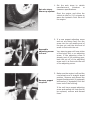
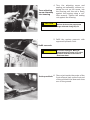
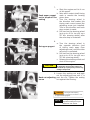
INSTALLATION
INSTRUCTIONS
REMANUFACTURED STEERING
BOXES
The installation procedures outlined in this booklet are intended to be used as a general
guide. Always refer to manufacturer’s service manuals for complete instructions on
mounting your steering gear for each application.
Upon being rebuilt your steering gear has been adjusted to factory
specifications. Red rubber coating has been put on these
adjustment points and must not be tampered with. Blue rubber
coating has been put on poppet adjustment points where
applicable and poppet adjustment must be performed. Failure to
perform poppet adjustments at blue coated points will affect
warranty consideration.
As recommended by all power steering manufacturers, a flow and
pressure gauge should be used in troubleshooting and installation
of power steering components. This will aid the installer in diagnosis
of problems and aid in poppet adjustments, etc.
Keep your system clean:
We recommend that when a power steering gear or pump has been rebuilt or
replaced:
• All hoses and fittings are inspected
• Fluid is flushed and replaced
• All filters are changed
Fluid
The steering system must be kept filled to the specified levels at all
times. Any mixture or unapproved oil could lead to seal deterioration
and leaks.
TRW/ROSS
ATF Type “E’ or “F”
Ford Spec. M2C138CJ
Dexron II or III
Mack EO-K2 Engine Oil
Texaco SAE 10W40
Texaco SAE 15W40
SHEPPARD
10W40 Motor Oil
Note: Series 5 & 6 Gears may be operated
with ATF
GM Power Steering Fluid, Hydraulic Fluid or
Dexron
Motor Oil is Preferred
Note: M - Series gears may use 15W40,
Dexron II or III
Power Steering Fluid and ATF Type E & F
Air Bleeding Single Steering Systems
For steps 1 and 2, do not turn
steering wheel. Otherwise air
may be induced into the system.
CAUTION
1. Fill the reservoir to nearly full. Crank the engine for 10 seconds
without allowing it to start, if possible. If the engine does start, shut
off immediately. Check and refill reservoir. Repeat at least 3 times,
each time checking and refilling the reservoir.
CAUTION
Do not allow the fluid level to
drop significantly or run out of the reservoir.
This may induce air into the system.
2. Start the engine and let it idle for 2 minutes. Shut the engine off and
check the fluid level in the reservoir.
3. Steer vehicle left and right several times but avoid steering full
stop. Add fluid, as necessary, to full line on the dipstick. The above
procedure should remove all air from the steering system; unless the
gear is mounted in an invert position and is equipped with a manual
bleed screw, commonly found in TRW/ROSS steering gears. If so,
refer to step 4.
4. Follow steps 1, 2, and 3. Leave engine idling. With the steering gear
in its center position, loosen the manual bleed screw about 1 turn,
allowing the air and aerated fluid to “bleed out” around the bleed screw
until only clear (non-aerated) fluid is bleeding out. Then close the
bleed screw (5/16th inch socket required). Check and refill reservoir.
Repeat procedure 3 or 4 times. Torque the manual bleed screw to
27-33lbs.
CAUTION
Do not move pitman arms by
hand as this could introduce air into the system.
Air Bleeding Dual Steering Box Systems
With the steering gears installed, install the pitman arms to manufacturer’s
specifications on appropriate timing mark. Ensure the arms will not
interfere with any object when gears are stroked full travel. Fill
reservoir, set park brake and fast idle engine.
During bleeding process, check fluid in reservoir, add as required.
With engine running and drag links disconnected, turn steering wheel left
and right until slave gear strokes to full travel. Repeat 3 or 4 times.
Install drag link on master box and repeat stroking slave a few more times.
Turn steering wheel to align slave gear pitman arm to align with drag link
and install.
CAUTION
Do not move pitman arms by
hand as this could introduce air into the system.
Air bleeding for an assist cylinder procedures are same as gears, only
disconnect rod end and stroke unit in and out to full travel. Ensure rod will
not interfere with any object.
For RCS series slave gears, refer to manufacturer’s specifications or contact
supplier.
Poppet Adjustment
HF, HFB, 292,392, 492, 592, M-Series
The relief valve plunger adjustment is provided to automatically reduce
the steering pressure when the road wheels have reached their limits
of turn. This keeps the supply pump from operating at its maximum
relief pressure when the road wheels are at their steering limits. System
temperatures are therefore reduced and high stress loads on the
mechanical components of the steering system are relieved.
High pressure oil at either end of the piston will push the relief ball valve
off its seat and fill the relief passage with oil at high pressure. At the
opposite end of its passage the relief ball valve is held against the seat
and holds the high pressure in the relief passage. As the piston moves
close to limits of stroke, the adjustable relief plungers push the relief
ball off its seat and the pressure is relieved. The distance the piston can
move is dependant upon the total from axle/steering geometry and tire
size. The relief valve plungers are adjustable to allow for variations or
change in these areas.
Adjustment Procedure:
1. Start engine and allow it to run at idle speed
2. Turn the steering wheel in one direction until a high pressure hiss is
heard or the axle stops contact.
3. Turn the relief plunger in or out until the high pressure hiss is heard
when ⅛th to 3/16th inch clearance between the axle stops.
4. Repeat this procedure for the opposite direction of steer and adjust
the relief valve plunger on the opposite end of the steering gear.
TRW TAS Series Gears
All TAS series gears are equipped with a grease fitting by the sector shaft that
must be greased using NLG 1 grade 2 chassis lube, using hand operated
grease gun. Add grease until it begins to extrude past sector shaft dirt and
water seal. It is recommended this be performed quarterly, more in severe
applications. Your rebuilt unit has been pre-greased upon rebuilding.
Failure to perform above procedures will affect warranty considerations.
Service Bulletin #TAS-101
On-Vehicle Poppet Readjustments for TAS Gears
What are poppets?
Poppets are pressure unloading valves set to trip just before full turn is reached
in each direction. When this procedure is completed correctly, system pressure
will be reduced before the axle stop screw contacts the axle stop in both
directions.
To determine if the poppets require readjustment or if they are performing
properly, install a Power Steering System Analyzer (PSSA) between the power
steering pump and the steering gear. If poppet readjustment is necessary,
you can leave the PSSA in the system to verify that the following procedure is
completed properly.
Why poppets might need to be readjusted:
•
•
•
•
•
•
•
After steering gear has been rebuilt
Changing to larger tires
Reduced vehicle wheel cut
Pitman arm mistimed, condition corrected
Steering gear being installed on a different truck
Steer axle stop bolt(s) were bent or broken
Steer axle U-bolt(s) were bent or broken
Note:
This resetting procedure will work in most cases with at least 1 ¾ hand wheel
turns from each side of center. If you’re making a large reduction in wheel
cut and this procedure does not work, you may have to internally reset the
poppets using the procedure described in the TAS service manual.
1. Set the axle stops to vehicle
manufacturer’s
wheelcut
or
clearance
specifications.
Set axle stops,
Warm-up system
Start the engine and allow the
vehicle to idle for 5-10 minutes to
warm the hydraulic fluid. Shut off
the engine.
Assemble
adjusting screw
into nut
2. If a new poppet adjusting screw
and nut are being used, turn the
screw into the non-sealing end of
the jam nut until the drive end of
screw is flush with the nut.
Your steering gear will have either
a fixed stop bolt or an adjusting
screw. If the adjusting screw is
already part of the steering gear,
back the nut off of the adjusting
screw until it is flush with the end
of the adjusting screw.
3. Make sure the engine is off and the
road wheels are in straight ahead
position. Remove and discard the
poppet fixed stop bolt (if equipped)
Remove poppet
and washer (if equipped) from the
stop bolt
lower end of the housing.
If the unit has a poppet adjusting
screw and sealing nut that need to
be replaced, remove and discard
them.
4. Turn the adjusting screw and
sealing nut assembly, without rotating the nut on the screw, into
Turn adjusting
the housing until the nut is firmly
screw assembly
against the housing using a 7⁄32”
into housing
Allen wrench. Tighten the sealing
nut against the housing.
CAUTION
If the drive end of the screw is below
the face of the nut, the poppet seat
flange will break during step 7d.
5. Refill the system reservoir with
approved hydraulic fluid.
Refill reservoir
CAUTION
Do not mix fluid types. Mixing of
transmission fluid, motor oil, or other
hydraulic fluids will cause seals to
deteriorate faster.
Jack up vehicle 6. Place a jack under the center of the
front axle and jack up the front end
of the vehicle so the steer axle tires
are off the ground.
7.
a. Start the engine and let it run
at idle speed.
b. Note which output shaft timing
Push upper poppet
mark is nearest the housing
out to prepare it for
piston bore.
setting
c. Turn the steering wheel in
the direction that makes this
timing mark move toward the
adjusting screw just installed.
Turn in this direction until axle
stop contact is made.
d. Pull hard on the steering wheel
(put up to 40 lb. rim pull on a
20” dia. steering wheel) after
the axle stop is contacted.
8.
Set upper poppet
CAUTION
a. Turn the steering wheel in
the opposite direction (end
of timing mark away from
adjusting screw) until the other
axle stop is contacted.
b. Pull hard on the steering wheel
(put up to 40 lb. rim pull on a
20” dia. steering wheel).
c. Release the steering wheel and
shut off the engine.
Do not hold the steering wheel at full turn
for more than 10 seconds at a time; the
heat build-up at pump relief pressure may
damage components.
9. Loosen the sealing nut and back
out the adjusting screw until 1” is
Back out adjusting past the nut. Tighten the sealing
screw
nut against the housing.
WARNING The length of the adjusting
screw beyond the nut must be no more than 1 1/16”
for proper thread engagment
NOTE
The length of adjusting screw
beyond the sealing nut may be
different for each vehicle.
10.
Set lower poppet
11.
Position adjusting
screw
a. Start the engine and let it idle.
b. Turn the steering wheel in
the original direction (end of
timing mark toward adjusting
screw), until axle stop contact
is made.
c. Hold the steering wheel in
this position (with up to 40 lb.
rim pull) for 10 seconds, then
release. Repeat this hold and
release process as many times
as necessary while completing
step 11.
a. With steering wheel held tightly
at full turn loosen the jam nut
and hold it in place with a
wrench.
b. Turn the adjusting screw
in (clockwise) using fingerpressure only (don’t use a
ratchet), until the Allen wrench
stops. Do not attempt to turn
it in further. Pause the turningin process each time the driver
releases the steering wheel;
continue turning only while the
wheel is held at full turn.
c. Back off the adjusting screw 3¼
turns and tighten the sealing
nut. Torque sealing nut to 35
lbf•ft.
12.The poppets have now been
completely reset. Lower the
vehicle. Check the reservoir and fill
if required.