1
DIGITAL SPEAKER PROCESSOR
DS48
•User Guide
•Reference Manual
professional products
®
i
IMPORTANT SAFEGUARDS
CONTENTS
Jump ahead to
quick start
DS48 Features
……………………………………………………………………iv
1 Introduction ………………………………………………………………………v
2 What is a Speaker Management System? ……………………………………1
2.1 Crossover ……………………………………………………………………1
2.2 Equalization …………………………………………………………………1
2.3 Delay
………………………………………………………………………1
2.4 High Pass and Low Pass Filters …………………………………………1
2.5 Limiting ………………………………………………………………………1
2.6 Signal Distribution……………………………………………………………1
3 Front Panel ………………………………………………………………………2
4 Rear Panel
………………………………………………………………………3
5 Quickstart
………………………………………………………………………4
6 Installation
………………………………………………………………………6
6.1 Rack Mounting ………………………………………………………………6
6.2 Connectors……………………………………………………………………6
7 Operation
………………………………………………………………………7
7.1 Navigating Front Panel Controls …………………………………………7
7.1.1 Hints for Operation ………………………………………………7
7.2 Submenus ……………………………………………………………………8
7.2.1.1 Crossover Submenu ……………………………………………8
7.2.1.2 Load a Xover ……………………………………………………8
7.2.1.3 Design a Xover …………………………………………………8
7.2.1.4 Store a Xover ……………………………………………………8
7.2.1.5 Erase a Xover ……………………………………………………8
7.3 Security Submenu …………………………………………………………8
7.4 Subsystem Submenu ………………………………………………………9
7.5 Interface Submenu …………………………………………………………10
7.6 Parameter……………………………………………………………………10
7.6.1 Gain ………………………………………………………………10
7.6.1.1 Inputs ……………………………………………………………10
7.6.1.2 Outputs …………………………………………………………10
7.6.1.3 Polarity …………………………………………………………11
7.6.1.4 Delay ……………………………………………………………11
7.6.1.5 HPF ………………………………………………………………11
7.6.1.6 LPF ………………………………………………………………11
7.6.1.7 PEQ ………………………………………………………………12
7.6.1.8 Limiter ……………………………………………………………12
7.6.1.9 Name of channel ………………………………………………13
7.6.1.10 Input Signal ……………………………………………………13
7.6.1.11 Copy Output Data ……………………………………………13
7.7 DS48 BLOCK DIAGRAMS ………………………………………………14
8 Graphical User Interface (GUI)…………………………………………………19
8.1 MINIMUM SYSTEM REQUIREMENTS …………………………………19
ii
CONTENTS
®
8.2 INSTALLING SYSOMAX ON YOUR COMPUTER ………………………19
8.3 STARTING UP SYSOMAX …………………………………………………20
8.3.1 From the Start menu ……………………………………………20
8.3.2 From Windows Explorer or My Computer ……………………20
8.4 Navigating SYSOMAX ……………………………………………………20
8.4.1 Top Line Menu……………………………………………………21
8.5 Device Program Manage/Memory ………………………………………22
8.6 Lock Unit ……………………………………………………………………23
8.7 Help
……………………………………………………………………23
9 Creating a Program ………………………………………………………………24
9.1 GAINS
……………………………………………………………………25
9.1.1 Input Signal Selection ……………………………………………25
9.1.2 Output ……………………………………………………………25
9.2 Delays
……………………………………………………………………26
9.3 Limiters ……………………………………………………………………26
9.4 Out 1, Out 2, etc. …………………………………………………………27
9.5 Crossover Filters ……………………………………………………………27
9.6 Parametric Equalizers: ……………………………………………………29
10 SPECIFICATIONS ………………………………………………………………30
11 Service
……………………………………………………………………31
12 Warranty
……………………………………………………………………31
13 Maintenance ……………………………………………………………………32
IMPORTANT! BEFORE YOU BEGIN, PLEASE CHECK THE CONTENTS WITHIN
THIS BOX TO INSURE THESE ITEMS ARE INCLUDED:
1. The BBE DS48 Digital Speaker Processor.
2. The BBE DS48 Digital Speaker Processor User’s Manual.
3. Power cord.
4. Warranty registration card.
5. Software Disc
6. DB-9 type serial cable for connection between unit and PC.
If any of these items are found to be damaged or missing, immediately contact
the BBE dealer you purchased it from. This manual will help you to effectively
utilize the BBE DS48. Reviewing the information contained in this manual will
answer most of the common questions that our service department receives.
If you still have questions, please feel free to call 800-233-8346.
iii
DS48 FEATURES
Crossovers
• 4 inputs 8 outputs and includes 10 configurations
Parametric
Equalizers
• Choice of Operating and Crossover Modes: 4 X 2-way, 2 X 3-way + 2 Aux,
2 X 4-way, 1 X 5-way + 3 Aux, Mono Dist., Stereo Dist., LCRS w/Mono
Subs, 4 X 4 Processor, Muted/Flat Startup
Driver
Alignment
Delay
Speaker
Protection
limiter
10 user
memories
• Input gain control for each channel
• Separate crossover controller
• 5 band fully parametric equalizer
• Driver Alignment Delay for each output up to 7ms in .1ms increments
• Output gain and phase control
• Three front panel encoders to speed programming
• Security lockout to discourage system tampering
• RS-232 remote control PC interface (Windows compatible software
included)
• Each group parametric equalizer has 360 ISO frequencies with + or 12dB gain
• Each group Q value is from 0.5 to 128 and provides Hi shelf/Lo shelf
select function.
• Separate limiter with Attack, Hold, Decay and Threshold parameters
• High Pass and Low Pass filter avail for each channel @ 6 or 12dB slope
• Choice of 6dB, 12dB,18dB, 24dB, 48dB Butterworth, Linkwitz-Riley or
Bessel frequency response curve
• Memory for up to 30 on-board user programs
• 8X7 bit input/output precision digital LED meter.
• 2X20 LCD backlit. LED Display
iv
®
INTRODUCTION
Thank you for choosing the BBE DS48 Speaker Management System. This
product will enable you to obtain the best possible performance from your
loudspeaker system. You can also reduce the amount of outboard gear that
is required to transport, set-up and operate as part of the sound system.
The DS48 offers many powerful functions. It is highly recommended that you
read through this manual before you begin connection and operation. For
those that are familiar with this type of device or if you simply can't wait to
hear how good your system will sound, a Quick Start section follows on
pages 4-5.
SOME TERMS THAT WILL BE USED IN THIS MANUAL:
Configuration: This refers to a particular group of settings, with
the primary parameter being the crossover type.
Program: A program is a configuration with either the factory
default or a user-created name.
Configuration and Program may be used interchangeably, though
a configuration must be programmed for a program to exist.
Parameter: A component of a setting such as the center frequency of one band of parametric EQ or the attack time of a limiter.
WARNING! To prevent possible speaker or
amplifier damage, always power-up peripheral
devices first, wait 10 seconds, and then turn on the
power amplifier. Turn off power amplifier first, then
power-down peripheral devices.
v
WHAT IS A SPEAKER MANAGEMENT SYSTEM?
A Speaker Management System uses digital signal processing to accomplish multiple functions that affect the audio signal between the mixer and
the power amplifiers. These functions include crossover, equalization,
delay, limiting, high-pass and low-pass filtering as well as signal distribution. Programs may be created, selected and edited with the DS48's front
panel controls. However, to create new programs, it is best to use the
included free PC software and configure the programs using the graphical
user interface (GUI) and a Windows PC.
2.1 Crossover:
This function uses filters to divide the audio spectrum into multiple bands, such as Highs,
Mids, and Lows. When these separate signals are individually amplified and sent to a
speaker matched for that range, the result is a much more efficient system with more
punch and clarity as compared to system using a two or three-way speaker box with a
passive cross-over. The common terms used for two or three-way systems are "bi-amp"
and "tri-amp".
2.2 Equalization:
This function provides control of the tonal spectrum. It can be used to compensate for differing acoustic conditions, speaker cabinet responses or boosting/cutting certain frequency ranges to create a specific type of sound. In some rooms, "ringing" or feedback is
present due to a number of conditions. Use the PEQ function to reduce the ringing frequencies.
2.3 Delay:
This function is used to "time-align" the different transducers in a speaker system. A
properly aligned system will have better phase coherence resulting in more focused
sound.
2.4 High Pass and Low Pass Filters:
These are used to reduce any signal outside of the desired bandwidth and are part of the
equalization function. This frees the power amps and speakers from trying to reproduce
signals that are not an intended part of the mix or simply beyond the reproduction range
of the loudspeakers.
2.5 Limiting:
This function prevents a signal from exceeding a certain pre-determined level. It prevents
input overload with its resultant distortion and also keeps amplifiers from clipping, which
protects the speakers.
2.6 Signal Distribution:
This allows the signals from each of the four inputs to be processed and sent to the corresponding output. The crossover function is not active when in this mode. An LCRS (Left,
Center, Right, SUB) mode is also available.
1
FRONT PANEL
®
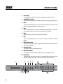
1. LCD Display
The 2x20 backlit LCD displays the program and programming choices of the unit.
2. <BACK/NEXT> Buttons
These buttons allow navigation for selection of sub-menus and some parameter values.
3. Menu
This is one of two buttons that will access the front panel programming. This one is used
primarily to select which program to call up, edit or save.
4. Gain
This is one of two buttons that will access the front panel programming. This, along with
the <Back/Next> buttons accesses the various parameters of a program.
5. Enter
Hitting this button will write the current selection to memory.
6. Quit
This exits the programming menu and returns the display to showing the selected
program.
7. FREQ Encoder Knob
This acts as the main value selector dial for most parameters other than those associated with EQ, Q and EQ Gain.
8. Q Encoder Knob
This adjusts the Q of a selected equalizer band.
9. GAIN Encoder Knob
This adjusts the Gain levels of Inputs, Outputs and any selected equalizer band.
10. Input Meters
These display the levels of the four inputs. The seven LED lamps per display are in 6 dB
steps from –30dbV to –6dBV, then -3dBV, then Limit (0dBV), then Clip (+8 dBV)
�
� ���
� ���
2
10
11
12
FRONT PANEL
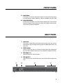
11. Output Meters
These display the levels of the eight output channels. The seven LED lamps per display
are in 6 dB steps from –30dbV to –6dBV, then -3dBV, then Limit (0dBV), then Clip (+8 dBV)
12. Output Mute Buttons
Pressing one of these buttons will mute the respective Output channel and the LED will
illuminate. All outputs will mute automatically during certain program selection and editing processes, to protect the loudspeakers
REAR PANEL
1. Power Jack
This accepts a standard IEC type AC bayonet plug. Because the unit uses universal
switching power supply, no voltage selection is required. The ON/OFF power switch is also
located here.
2. RS232 Interface
Connect this to the serial port on a PC using the included cable or other standard DB-9
type cable. With the software installed, the PC can now monitor and program the DS48.
3. XLR Outputs 1-8
These are balanced (Pin 2 Hot) XLR outputs.
4. XLR Inputs A-D
These are balanced (Pin 2 Hot) XLR inputs that accept the signal from the outputs of the
mixer.
�
�
�
�
3
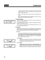
QUICK START
®
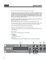
NOTE: This section will describe navigation of the front panel controls as follows:
The button to press will be shown in ALL CAPITALS. For QUICK START, a number following in
parentheses (#) will also be included. These refer to the same names and numbers as shown
in Figure 1, Front Panel Controls and Indicators. The expected display text is shown in "quotation marks". If you press a button and the display does not change, it means that the button has no effect for that particular menu item.
If you get to a certain point in the menu and want to go back, but cannot, press QUIT (6) and
begin the steps again. This is normal for the unit.
1. Before hooking up the system, make sure that all items are OFF, especially the power amps.
2. Use high quality balanced XLR mic cables to make the connections. The feeds from the DS48 at "front of
house" can also be sent through the audio snake returns to the amp stacks if used in a live setting.
3. You should know the frequency response and limits of your loudspeakers
4. Connect the main output or outputs of your mixer to the inputs of the DS48.
5. Depending on the configuration you select, connect the appropriate number of outputs from the DS48 to your
power amp inputs.
6. Turn on the DS48.
7. After a brief start up, the display will show "2 x 2 WAY X-OVER"
8. Press MENU (3).
Press ENTER (5).
Press NEXT (2) "Design a Xover"
9. Press ENTER (5).
Select the crossover mode desired with the BACK/NEXT (2) buttons. After selection, Press ENTER (5).
�
�
�
4
���
� �
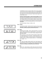
QUICK START
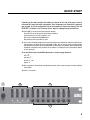
Depending on the mode selected, other options will appear for this level of the menu, primarily
concerned with input and output assignments. Some assignments are fixed with the crossover
type selected. Only those assignments that can be selected will show on the display. Either the
BACK/NEXT (2) buttons or the Parameter dial will work for stepping through the selections.
10. Press GAIN (4). Set the gain for Input A with gain knob (9).
Press NEXT (2) and set the gain for Input B with gain knob (9).
Repeat procedure to set gain for outputs C & D.
Gain value is selected with the GAIN knob (9).
After setting all gains, press NEXT (2) again.
11. You are now in the Output programming section. Depending on the configuration selected, the different outputs will show in the upper left corner of the display as OP1, OP2, etc. You can select an output and then
step through the parameters of with the BACK/NEXT (2) buttons OR use the GAIN (4) button to step through
the outputs, changing the same parameter for each output as it is displayed and cycle through the outputs
for each parameter.
12. In the PEQ screen, the ENTER (6) button is used to toggle between
✧”,
PEQ “
Low Shelf “}”,
Hi Shelf “{“, and
Bypass “=”
13. After completion of the patching and programming, power up the rest of the system and enjoy improved
sound quality.
14. Practice “safe sound”.
�
10
11
12
5
INSTALLATION
®
Your DS48 was carefully packed at the factory and the packaging was
designed to protect the unit from rough handling. Nevertheless, we recommend that you carefully examine the packaging and its contents for any
signs of physical damage that may have occurred in transit.
6.1 RACK MOUNTING
The DS48 fits into one standard 19” rack unit of space. Please allow at least an additional 4” depth for the connectors on the back panel. Though this device does not generate
significant heat, be sure that there is enough air space around the unit for cooling. To
avoid overheating, do not place the DS48 in rack above devices that generate significant
heat such as power amplifiers.
6.2 CONNECTORS
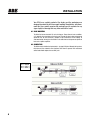
The DS48 must be installed using standard 3 –pin type XLR jacks. Although the inputs are
fully balanced, the automatic servo-functions allow them to operate with unbalanced
source/loads. Audio outputs also use XLR jacks.
PIN 1 = Ground
PIN 2 = HOT (+)
PIN 3 = COLD (-)
6
OPERATION
There are two methods of creating and selecting programs on the DS48.
1.The first method uses the front panel controls of the unit and requires
stepping through menus to access the proper parameters that need
adjusting. Once programs have been saved to the onboard memory, calling up a program is quite simple. See QUICKSTART for an example of navigating and creating a program.
2.The second method uses the included Graphical User Interface (GUI)
software run on a Windows PC. The computer connects to the DS48 and
gives a more global view of the parameters and the choices for settings.
This is the most efficient method to create the programs you use most and
want to save to memory on the unit. They can then be called up as needed. If an adjustment is required and it is not convenient to hook up a PC,
the edits can be made from the front panel controls of the unit. The
Sysomax software also lets you monitor and remote control a DS-48 in real
time from your computer.
NOTE: More detailed descriptions of how the various functions work are in
Section 8, Creating A Program.
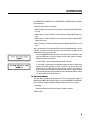
7.1 Navigating Front Panel Controls
There are six buttons and three encoder knobs on the front panel, as well as mute buttons for each of the outputs. In conjunction with the display, the six buttons and three
knobs let you create, edit, save, recall and delete programs. You can also set security levels as to how much access to the programming menus, if any, is available to multiple
users.
When the unit powers up, it will display the currently selected program by showing either
the crossover type or a name for that program that has been selected and saved.
7.1.1 Hints for Operation:
The MENU and GAIN buttons access the different levels of the available selections.
MENU is used to access submenus for Crossover, Security, Subsystem and Interface.
The GAIN button is used to access specific parameters for a configuration
NOTE: In some sub-MENU items, both the arrow keys and the FREQ knob will select
different parameter values. If you get to a spot where you need to step back and the
7
OPERATION
®
BACK button will not step you back, simply hit EXIT and start again.
Where an additional "ENTER" press is required to write the selection to memory, the
screen will prompt you with "[ENTER] to Confirm".
The LED display also offers some navigation help. Left or right arrows on the top line
indicate the BACK/NEXT buttons will step to other choices.
7.2 SUBMENUS
7.2.1.1 Crossover Submenu
This menu selects the type of crossover and is the primary submenu to create,
recall, delete, and name a program configuration.
Press MENU and ENTER to access this submenu. Then use the BACK, NEXT and
ENTER buttons to adjust the Xover Submenu. Included submenus follow:
7.2.1.2 Load a Xover:
This will load a configuration that has previously been saved into the memory
of the unit. Until you have saved other programs into the unit, nothing will be
available to load. Only the previously selected program will display.
7.2.1.3 Design a Xover;
Use this mode to select from the ten different types of X-OVER and distribution
configurations.
7.2.1.4 Store a Xover:
Store all the configuration settings of a X-OVER. The DS48 will store up to 30
program configurations in user memory locations. (An unlimited number can be
stored on a PC or other PC accessible memory.) Each of the 30 programs can
have a name containing up to 16 letters and numbers. If the program name is
not edited, it is stored under the corresponding mode name, such "2 x 4 WAY
XOVER".
7.2.1.5 Erase a Xover:
This will delete a user-created configuration.
7.3 Security Submenu
This menu allows you lockout various combinations of any or all front panel programming
functions. A password with up to four-characters is created by the primary user and
entered using the FREQ knob to select the character and the BACK/NEXT buttons to move
the cursor to the four available spaces. To unlock the system, the password must be reentered.
8
OPERATION
Press MENU, NEXT and ENTER. Then use the NEXT/BACK and ENTER buttons to adjust the
Security Submenu.
The various locking modes are as follows:
1. LOCK: Changes only: Parameters can be viewed, but cannot be adjusted. MUTE buttons
are valid.
2. LOCK: Changes + View: Parameters cannot be viewed or adjusted. MUTE buttons are
valid.
3. LOCK: Changes + Mutes: Parameters can be viewed, but cannot be adjusted. MUTE
buttons are not valid.
4. LOCK: Everything: Parameters cannot be viewed or adjusted. MUTE buttons are not
valid.
Once a security mode is selected, press ENTER. You will be prompted to enter a security
code. This can be from one to four characters. Any of the characters available from the
on-board selection choices may be used.
A. Press the BACK/NEXT buttons to shift the cursor to one of the four positions. Then
rotate the FREQ knob to select the desired character (letter, number or symbol).
Repeat for the other three positions.
B. Press “ENTER”, confirm the password and display as follows:
C. The system is locked when the reentered password matches the original entry
otherwise the locking operation is invalid. If invalid, the screen will show “Bad
Confirmation". If the codes match, the screen will show "Lock Success". Though up
to four characters may be used, the lock out will work with just a single character.
The initial and confirming entry must both be in the same position. NOTE: If nothing
is entered (all blanks) the unit will still lock.
7.4 Subsystem Submenu
This menu allows selection of Input Linking and a choice of "wake up time" fade in or
Mute Hold. Press MENU, NEXT and NEXT again. Then use the BACK/NEXT and ENTER buttons to adjust the Subsystem Submenu. Subsystem Submenu items are as follows:
1. Input option:
Determines whether the A/B and C/D inputs are linked or separate.
2. Wake up time:
9
OPERATION
®
A. Determines whether the outputs will stay muted on power up until manually
switched off (Mute Hold) or the level will gradually fade up to the operating level
(Fade In). The fade-in time is fixed.
Wake up 1 Fade-in: Mutes are off, but Output channels rise to programmed levels
gradually.
Wake up 2 Mute Hold: All Output channels are muted until the mutes are manually
disabled either on the front panel or through the GUI.
7.5 Interface Submenu
This submenu selects the remote ID number for the unit. This number is identified by the
PC when connected for programming.
Press MENU, then NEXT three times and then ENTER. Use the BACK/NEXT or FREQ knob
to enter an ID value between 1 and 64.
Use this function when multiple DS48 units are used. Master Control unit is set as 1; slave
units are set with subsequent numbers.
7.6 Parameter
Parameter lets you set the specific values for a configuration. These are set for the outputs of the device. Inputs require only a gain setting. Parameters for Outputs include such
things as polarity, EQ, Limiter, Delay, HiPass Filter, LoPass Filter, and Filter Type.
7.6.1 Gain:
The first press of the GAIN button will go to Input Level adjustment for A or A&B if the
first two inputs are linked. Repeated pressing of the NEXT button will step through
the succeeding inputs and continue to the Outputs. Once in Outputs, additional
presses of GAIN will cycle you through the eight output channels. Use the BACK button to cycle back to the Inputs if needed.
7.6.1.1 Inputs:
Press GAIN to enter the Parameter setup menu. Set the gain for Input A using
the FREQ knob. Press NEXT and set the gain for Input B using the FREQ knob.
Repeat procedure to set the GAIN for Inputs C and D.
7.6.1.2 Outputs:
Press NEXT again and the screen will display an Output (Op1 = Output 1). Set
the desired input gain level. At this point you can use the BACK/NEXT buttons to
step through each of the parameters for the currently selected output. Press the
GAIN button again to go to the next Output and program all of its parameters.
10
OPERATION
(The GAIN button will now select only the Output channels; the gain adjustment
screens for the Inputs will not be displayed unless you use the BACK/NEXT buttons or exit the menu and start again.) Each Output will have both a number and
name displayed. The names are taken from a default list with labels such as
Low, Mid, Highs, Sub, etc.
An alternate method is to program a single parameter for Output 1, such as
DELAY, then press the GAIN button to go to each of the Output channels in turn
and program the delay parameter for that channel. Now select the next parameter and program that for each of the outputs in sequence. In some cases this
may make it easier to keep track of the comparative values between outputs.
For simplification, we will follow though programming all the parameters for a
single output.
Set the Gain for Output 1. Range is –40 dB to + 6 dB
7.6.1.3 Polarity:
Set the polarity for Output 1. Switching this will change the phase of the signal
180 degrees. If Outputs are linked, reversing the polarity of one of the linked
channels will also reverse the polarity of the other linked channel.
7.6.1.4 Delay:
Set the Delay time for Output 1. Delay is used to align drivers in a stack that
may be in different vertical planes or multiple speaker in a stack. Delay range
is 0ms to 7ms selectable in .1 ms increments. The delay is displayed in milliseconds, meters and feet.
NOTE: Though there are some variables, generally speaking the speed of sound
in 71 degree Fahrenheit dry air at sea level is ~773miles per hour. This is ~345
meters per second and about 1.13 feet per millisecond. .5 milliseconds equates
to about 6.78 inches. .1 milliseconds equates to about 1.36”. The DS48 displays
1ms = 343mm = 1.1ft.
7.6.1.5 HPF:
This is part of the crossover function. Sets the "knee" (corner frequency) and
filter slope type for the HiPass Filter (HPF). Frequencies below the selected frequency will be filtered by the selected filter type and slope. Rotate the FREQ
knob to select the frequency and the Q knob to select the filter type.
7.6.1.6 LPF:
Set the "knee" (corner frequency) and filter slope type for the LoPass Filter
(LPF). Frequencies above the selected frequency will be filtered by the selected
11
OPERATION
®
filter type and slope. Rotate the FREQ knob to select the frequency and the Q
knob to select the filter type.
HiPass: frequency range 10Hz~16.0KHz
LoPass: frequency range 35Hz~22.0KHz
Use HPF and LPF together to define the frequency band for this channel of the
crossover.
7.6.1.7 PEQ:
NOTE: when using Hi shelf or Lo shelf, set
Gain=0.0dB, change Q-value to Hishelf/Loshelf.
✧
}
{
=
Set the parameters for the five available bands of parametric EQ. Use the FREQ,
Q and GAIN knobs to adjust the three parameters in the display. These include
Frequency, Q, and Gain (Cut or Boost). Pressing the ENTER button in this mode
will select the symbol in the upper right corner. Depending on other settings, the
choices will include some or all of the following:
✧ (PEQ), } (Lo shelf), { (Hi shelf), = (PEQ bypass)
means PEQ
The choices for the PEQ center frequencies are 360 ISO frequencies between
20 Hz and 20 kHz.
means Lo shelf
means Hi shelf
Q is 0.5 to 128 and Hi Shelf or Lo Shelf.
means PEQ bypass
Gain is +/- 12 dB
Input
7.6.1.8 Limiter:
Input
limiting
Threshold
Time
Time
The signal BEFORE gain control and AFTER
limiter processing
The limiter is used to limit the signal going to the output stage and ultimately
the amps, to a predetermined maximum level, with the intention of preventing
clipping and its resultant distortion.
There are four parameters available to set for the Limiter
1. Input Level sets the point at which the limiting circuitry will activate. This is
sometimes referred to as Threshold. The range is -20dBV to +15dBV. A lower
input level will activate the limiter sooner, affording more protection, but possibly creating more sonic artifacts if the limiter is activating and deactivating too
frequently. Ideally, the limiter should be set so that it activates occasionally on
peaks in the program.
This control is also tied to the front panel level display meter for its selected output. As you lower the Limiter input level, the sensitivity of the meter will
increase. This means a lower input level will result in the same signal showing
more level on the Output channel display. Ideally, the output level should just
approach and occasionally cross into limiting.
12
OPERATION
2. Attack. This is the amount of time that elapses before the limiter reduces the gain
to the program level after the threshold point has been exceeded by the incoming
signal. Generally, set shorter attack times on outputs that are feeding mids and
highs and longer attack times for lows and subs. The time should be chosen carefully as the danger of dynamics distortion usually increases with shorter attack
times. The attack time of the DS48 can be set within a range of 1 to 100 milliseconds.
3. Hold determines how long the limiter's gain reduction stays in place, even after
the input signal has fallen below the Threshold. Use this to smooth out "choppiness", "pumping" or other artifacts that may occur under certain settings and program material. The hold time of the DS48 can be set within a range of 0.0 to 100
milliseconds in 1ms increments.
4. Decay: This control determines the how quickly the limiter removes the gain
reduction and returns the signal to unity gain once the input signal has fallen below
threshold. In instances where the limiter is constantly and repeatedly activated, a
longer Decay time will prevent excessive retriggering and provide a more consistent signal. This control can be adjusted from 10ms to 1000ms in 10ms increments.
7.6.1.9 Input Signal:
In this menu, LCD displays the current input channel for the selected output. This
parameter can be adjusted through all 4 input sources.
7.6.1.10 Name of channel:
This function allows you to choose a name or label for an output channel. There is
a fixed list of 32 choices to choose from. Use the PARAM Rotate to change the channel name.
7.6.1.11 Copy Output Data
This allows you to copy the settings from one output channel to another, saving
setup time.
Press ENTER and select the source channel with either the FREQ knob or the
BACK/NEXT buttons. Press ENTER again and select the target channel to copy to.
Press ENTER and then ENTER again to confirm.
13
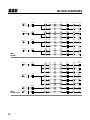
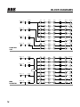
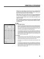
BLOCK DIAGRAMS
®
INPUT A
INPUT B
INPUT C
INPUT D
HPF
LPF
PEQS
Delay
GAIN
MUTE
LOW
OUTPUT 1
HPF
LPF
PEQS
Delay
GAIN
MUTE
HIGH
OUTPUT 1
HPF
LPF
PEQS
Delay
GAIN
MUTE
LOW
OUTPUT 2
HPF
LPF
PEQS
Delay
GAIN
MUTE
HIGH
OUTPUT 2
HPF
LPF
PEQS
Delay
GAIN
MUTE
LOW
OUTPUT 3
HPF
LPF
PEQS
Delay
GAIN
MUTE
HIGH
OUTPUT 3
HPF
LPF
PEQS
Delay
GAIN
MUTE
LOW
OUTPUT 4
HPF
LPF
PEQS
Delay
GAIN
MUTE
HIGH
OUTPUT 4
HPF
LPF
PEQS
Delay
GAIN
MUTE
LOW
OUTPUT 1
HPF
LPF
PEQS
Delay
GAIN
MUTE
MID
OUTPUT 1
HPF
LPF
PEQS
Delay
GAIN
MUTE
HIGH
OUTPUT 1
HPF
LPF
PEQS
Delay
GAIN
MUTE
LOW
OUTPUT 2
HPF
LPF
PEQS
Delay
GAIN
MUTE
MID
OUTPUT 2
HPF
LPF
PEQS
Delay
GAIN
MUTE
HIGH
OUTPUT 2
GAIN
HPF
LPF
PEQS
Delay
GAIN
MUTE
AUX
OUTPUT 1
GAIN
HPF
LPF
PEQS
Delay
GAIN
MUTE
AUX
OUTPUT 2
GAIN
GAIN
GAIN
GAIN
DS48
4X2 WAY
INPUT A
INPUT B
INPUT C
DS48
2X3 WAY + AUX
14
INPUT D
GAIN
GAIN
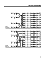
BLOCK DIAGRAMS
INPUT A
HPF
LPF
PEQS
Delay
GAIN
MUTE
LOW
OUTPUT 1
HPF
LPF
PEQS
Delay
GAIN
MUTE
MID
OUTPUT 1
HPF
LPF
PEQS
Delay
GAIN
MUTE
HIGH
OUTPUT 1
HPF
LPF
PEQS
Delay
GAIN
MUTE
LOW
OUTPUT 2
HPF
LPF
PEQS
Delay
GAIN
MUTE
MID
OUTPUT 2
HPF
LPF
PEQS
Delay
GAIN
MUTE
HIGH
OUTPUT 2
GAIN
HPF
LPF
PEQS
Delay
GAIN
MUTE
MONO SUB
OUTPUT 1
GAIN
HPF
LPF
PEQS
Delay
GAIN
MUTE
MONO SUB
OUTPUT 2
GAIN
HPF
LPF
PEQS
Delay
GAIN
MUTE
LOW
OUTPUT 1
HPF
LPF
PEQS
Delay
GAIN
MUTE
LOW MID
OUTPUT 1
HPF
LPF
PEQS
Delay
GAIN
MUTE
HIGH MID
OUTPUT 1
HPF
LPF
PEQS
Delay
GAIN
MUTE
HIGH
OUTPUT 1
HPF
LPF
PEQS
Delay
GAIN
MUTE
LOW
OUTPUT 2
HPF
LPF
PEQS
Delay
GAIN
MUTE
LOW MID
OUTPUT 2
HPF
LPF
PEQS
Delay
GAIN
MUTE
HIGH MID
OUTPUT 2
HPF
LPF
PEQS
Delay
GAIN
MUTE
HIGH
OUTPUT 2
GAIN
SUM
A+B
INPUT B
INPUT C
INPUT D
GAIN
2X3 + MONO SUB
INPUT A
INPUT B
INPUT C
INPUT D
GAIN
GAIN
GAIN
2X4 WAY
CROSSOVER
15
BLOCK DIAGRAMS
®
INPUT A
INPUT B
INPUT C
INPUT D
GAIN
GAIN
GAIN
GAIN
HPF
LPF
PEQS
Delay
GAIN
MUTE
LOW
OUTPUT 1
HPF
LPF
PEQS
Delay
GAIN
MUTE
LOW MID
OUTPUT 1
HPF
LPF
PEQS
Delay
GAIN
MUTE
HIGH MID
OUTPUT 1
HPF
LPF
PEQS
Delay
GAIN
MUTE
HIGH
OUTPUT 1
HPF
LPF
PEQS
Delay
GAIN
MUTE
SUB
OUTPUT 1
HPF
LPF
PEQS
Delay
GAIN
MUTE
AUX
OUTPUT 1
HPF
LPF
PEQS
Delay
GAIN
MUTE
AUX
OUTPUT 2
HPF
LPF
PEQS
Delay
GAIN
MUTE
AUX
OUTPUT 3
HPF
LPF
PEQS
Delay
GAIN
MUTE
OUTPUT 1
HPF
LPF
PEQS
Delay
GAIN
MUTE
OUTPUT 2
HPF
LPF
PEQS
Delay
GAIN
MUTE
OUTPUT 3
HPF
LPF
PEQS
Delay
GAIN
MUTE
OUTPUT 4
HPF
LPF
PEQS
Delay
GAIN
MUTE
OUTPUT 5
HPF
LPF
PEQS
Delay
GAIN
MUTE
OUTPUT 6
HPF
LPF
PEQS
Delay
GAIN
MUTE
OUTPUT 7
HPF
LPF
PEQS
Delay
GAIN
MUTE
OUTPUT 8
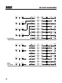
1X5 WAY AND
3 AUX
INPUT A
INPUT B
GAIN
GAIN
SUM
A+B+C+D
INPUT C
MONO
DISTRIBUTION
16
INPUT D
GAIN
GAIN
BLOCK DIAGRAMS
INPUT A
HPF
LPF
PEQS
Delay
GAIN
MUTE
LOW
OUTPUT 1
HPF
LPF
PEQS
Delay
GAIN
MUTE
LOW
OUTPUT 2
HPF
LPF
PEQS
Delay
GAIN
MUTE
LOW MID
OUTPUT 1
HPF
LPF
PEQS
Delay
GAIN
MUTE
LOW MID
OUTPUT 2
HPF
LPF
PEQS
Delay
GAIN
MUTE
HIGH MID
OUTPUT 1
HPF
LPF
PEQS
Delay
GAIN
MUTE
HIGH MID
OUTPUT 2
HPF
LPF
PEQS
Delay
GAIN
MUTE
HIGH
OUTPUT 1
GAIN
HPF
LPF
PEQS
Delay
GAIN
MUTE
HIGH
OUTPUT 2
GAIN
HPF
LPF
PEQS
Delay
GAIN
MUTE
HPF
LPF
PEQS
Delay
GAIN
MUTE
OUTPUT 2
HPF
LPF
PEQS
Delay
GAIN
MUTE
OUTPUT 3
HPF
LPF
PEQS
Delay
GAIN
MUTE
OUTPUT 4
HPF
LPF
PEQS
Delay
GAIN
MUTE
LOW
OUTPUT 5
HPF
LPF
PEQS
Delay
GAIN
MUTE
LOW MID
OUTPUT 6
HPF
LPF
PEQS
Delay
GAIN
MUTE
HIGH MID
OUTPUT 7
HPF
LPF
PEQS
Delay
GAIN
MUTE
HIGH
OUTPUT 8
GAIN
SUM
A+B
INPUT B
INPUT C
GAIN
GAIN
SUM
C+D
STEREO
DISTRIBUTION
INPUT D
INPUT A
INPUT B
GAIN
SUM
A+B+C+D
INPUT C
LCR WITH
MONO SUBS
INPUT D
GAIN
GAIN
OUTPUT 1
17
BLOCK DIAGRAMS
®
INPUT A
INPUT B
INPUT C
INPUT D
GAIN
GAIN
GAIN
GAIN
HPF
LPF
PEQS
Delay
GAIN
MUTE
HPF
LPF
PEQS
Delay
GAIN
MUTE
OUTPUT 2
HPF
LPF
PEQS
Delay
GAIN
MUTE
OUTPUT 3
HPF
LPF
PEQS
Delay
GAIN
MUTE
OUTPUT 4
HPF
LPF
PEQS
Delay
GAIN
MUTE
MUTED
OUTPUT 5
HPF
LPF
PEQS
Delay
GAIN
MUTE
MUTED
OUTPUT 6
HPF
LPF
PEQS
Delay
GAIN
MUTE
MUTED
OUTPUT 7
HPF
LPF
PEQS
Delay
GAIN
MUTE
MUTED
OUTPUT 8
HPF
LPF
PEQS
Delay
GAIN
MUTE
MUTE
OUTPUT 1
HPF
LPF
PEQS
Delay
GAIN
MUTE
MUTE
OUTPUT 2
HPF
LPF
PEQS
Delay
GAIN
MUTE
MUTE
OUTPUT 3
HPF
LPF
PEQS
Delay
GAIN
MUTE
MUTE
OUTPUT 4
HPF
LPF
PEQS
Delay
GAIN
MUTE
MUTE
OUTPUT 5
HPF
LPF
PEQS
Delay
GAIN
MUTE
MUTE
OUTPUT 6
HPF
LPF
PEQS
Delay
GAIN
MUTE
MUTE
OUTPUT 7
HPF
LPF
PEQS
Delay
GAIN
MUTE
MUTE
OUTPUT 8
OUTPUT 1
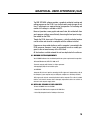
4X4 PROCESSOR
INPUT A
INPUT B
INPUT C
MUTED,
FLAT STARTUP
18
INPUT D
GAIN
GAIN
GAIN
GAIN
GRAPHICAL USER INTERFACE (GUI)
The BBE SYSOMAX software provides a graphical method of creating and
editing programs on the DS48. It can also be used to make changes in real
time, if adjustments are required during live operation. Full metering and
control of all settings is available on the PC.
Because it provides a more graphic and overall view, this method will allow
you to program settings more efficiently than using the front panel navigation method on the DS48.
Though the DS48 stores up to 30 programs, a virtually unlimited number
can be written and stored on a computer with the software installed.
Programs can be created whether or not the computer is connected to the
DS48 processor. However, it must be connected to write or modify programs to the on-board memory of the DS48 itself.
All the functions available onboard the unit are duplicated in the software.
8.1 MINIMUM SYSTEM REQUIREMENTS
Your SYSOMAX software has the following minimum system requirements for operation:
•Microsoft Windows 98, ME, NT4, 2000, or XP.
•Personal computer with Pentium 2 or higher processor.
•20 megabytes (MB) of free hard disk space.
•64 MB RAM.
•Computer RS-232 serial port for connecting the DB-9 type serial programming cable to
the computer (if your computer only has USB ports, adapters are commonly available.)
•DB-9 type serial cable for connecting the device to the computer. This cable is included
with the unit. Should it become lost or damaged, replacement cables are available at
electronics and computer supply stores.
8.2 INSTALLING SYSOMAX ON YOUR COMPUTER
To install SYSOMAX from the CD-ROM:
1. Insert the CD-ROM into the computer’s CD-ROM drive.
2. Select My Computer from the Desktop or Start menu.
19
®
GRAPHICAL USER INTERFACE (GUI)
3. Click on BBE (D) (CD-ROM drive is usually drive D)
4. Double click on the file that then displays: DS48Setup_v13.exe
5. The Setup Wizard screen will appear.
6. Follow the prompts displayed on the screen to install the program.
7. When the installation is complete, eject the CD-ROM
8.3 STARTING UP SYSOMAX
To create a preset program on a DS48 unit , first connect it to the computer with the serial cable. If your computer only has USB ports, adapters are available from computer suppliers.
NOTE: Alternatively, you can start SYSOMAX and create a program offline, without connecting to the unit. Always remember to save your programs. To upload the program to
the unit, you must then connect the cable between the unit and the computer.
After the connection is made you can start up SYSOMAX™ by using the Start menu on
your Windows desktop, or by using Windows Explorer or My Computer.
8.3.1 From the Start menu:
1. On the Windows taskbar, click the Start button.
2. From the Start menu, select Programs, then DS48. Then click on the next DS48
icon that appears.
8.3.2 From Windows Explorer or My Computer:
Use Windows Explorer or My Computer to navigate to the folder in which SYSOMAX
resides, then double-click the SYSOMAX.exe icon, or highlight it and press ENTER.
Once you have started the program, you can choose to either operate the program
online or offline to the unit. To exit the program, click the SYSOMAX Exit button in File
menu of the title bar.
8.4 Navigating SYSOMAX
1. When the program starts, the main screen will be displayed. This is a flow chart of the
various signal paths and processes.
2. You can select items from the drop down menus, the icons on the Toolbar or by clicking on one of the flow chart boxes.
20
GRAPHICAL USER INTERFACE (GUI)
8.4.1 Top Line Menu
Exit
This section provides an overview of the menu and screen choices. Those that
require a more detailed description are covered in subsequent sections.
1. Exit lets you select EXIT to exit the program.
2. Config provides six choices:
A. Online, which will open the RS-232 connection to the DS48 when it’s properly connected.
B. Offline, which will close the connection to the unit.
C. RS-232 lets you select the Com port for your particular computer.
D. Config opens the Config window. This window lets you select one of the ten
available modes.
E. Data Copy lets you copy settings from one port to another, saving repetitive
programming steps.
F. Lock/Unlock opens the Lock Unit window.
3. Program offers two choices: Device Program Manager which opens the Memory
Screen (see below) and Upload Current Program from Device, which will load the
program currently running on the DS-48 to the computer for editing and/or saving.
4. View lets you select whether or not to display the Toolbar and Status Bar on your
screen. The Toolbar is comprised of five Icons.
5. Help displays the version of the software.
6. Icon Bar offers five choices. From left to right they are :
A. M opens the Memory management window. This is where you can name,
save, erase, upload and download programs to.from the compute and the DS48.
{See 8.4.2}
B. RS232 Config
C. Online/Offline
D. Upload Current
E. About
21
GRAPHICAL USER INTERFACE (GUI)
®
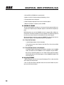
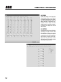
8.5
Device Program Manage/Memory
Clicking the Memory icon or selecting Device Program Manage form the Program
Menu will open a dialog box with a table displaying 30 memory locations and spaces
for names as well as 10 buttons.
To Store a program as a memory location, click on the desired Prog line in the table
for the desired save location. Then click either Store to Device or Store to PC. Write
a new name in text box if desired and click OK. The dialog box will close and you will
be returned to the main screen view.
Refresh will upload the stored programs in memory from the device to the computer.
To rename a program that has already been named, click on a program location in
the table, then click Rename. Enter the desired name in the text box and click OK.
The dialog box will close and you will be returned to the main screen view.
Recall downloads the current version of the selected program from the computer to
the device.
Erase will immediately erase a selected program. Use caution as there is no “confirm” window before the command executes.
22
GRAPHICAL USER INTERFACE (GUI)
Erase All will erase all programs in the memory table and in the device. There is a
confirm screen before this command executes.
Exit will close the window.
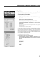
8.6
Lock Unit
Found under config dropdown menu
Provides four options for security lockouts in the pull-down menu. Make your selection and enter your password in the text box. You will then need to confirm the password and OK the lockout. To unlock the unit, under the Config menu, click on Lock/
Unlock Unit. Enter the password in the text box and click OK. Then click on the Clear
Password box.
NOTE: If you forget the password, there is a code to unlock the unit so you can reset
the password: COLO
8.7
Help
Provides the version information
23
®
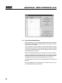
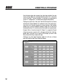
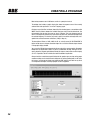
CREATING A PROGRAM
Once the device type and crossover type have been selected, the main
screen will show blocks for each programmable section. This is referred to
as the “Flow Chart”. The term “program” is used here as an equivalent to
“preset” or “configuration” as used on other programmable devices.
Clicking on any box in the “flow chart” other than the Input Gain or Source
will display the Device Window. This window has tabs at the top that provide access to all the other windows for various functions. Each function
window may in turn have additional windows. Simply click on the tab for
the desired function. If it is not the one that the window was opened under.
Example: Click on X-over for channel A. If Output 1 is assigned to Channel
A, then the crossover screen for Out-1 will appear with the Out-1 tab highlighted. Now if you want to set a delay for that output, just click on the
Delay tab and the Delays window will open.
Clicking on any of the Input Gain boxes (label In-A, In-B, etc.) or Source
boxes will open the Input Signal Selection Window.
24
CREATING A PROGRAM
Whenever any screen windows, other than the main one, are displayed, the
top-level menu will be disabled until the window is closed. To close a window, hit the escape key (esc) or Exit in the window.
When entering values into text boxes you can use your pointing device
such as a mouse or touchpad. You can also use the up/down/left/right cursor arrows for certain functions such as Gain sliders and up/down incremental value arrows.
NOTE: Downloading a program from the device to the computer will enable
the screen to graphically show the routing of input to outputs with different colored lines.
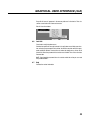
9.1 GAINS:
9.1.1 Input Signal Selection.
Clicking on an input Gain box or Source will open a new screen labeled Input Signal
Selection. This window offers gain adjustment for the four inputs plus routing assignment. The routing allows you to select which of the four inputs go to which of the
eight outputs. In all but the Mono and Stereo distribution modes, there are limits as
to how many and which outputs may be assigned to the inputs.
To set the Gain for an input channel, either use your pointing device to drag the slider to the appropriate setting, enter a value directly into the text box under the slider
or click on the slider until the border line appears and use your cursor keys. If a value
beyond the operating range is entered numerically, the system will default to the
closest minimum or maximum setting.
9.1.2 Output.
The Output channels add check boxes for Mute and 180º. Mute turns the Output
mutes on or off. If off, the default is for the channels to fade up when activated. The
180º when selected reverses the polarity of the signal for that channel.
These choices are also available for the selected output channel under the Out 1, Out
2, etc. tabs.
To set the Gain for an output channel, either use your pointing device to drag the slider to the appropriate setting, enter a value directly into the text box under the slider
or click on the slider until the border line appears and use your cursor keys. If a value
beyond the operating range is entered numerically, the system will default to the
closest minimum or maximum setting.
25
®
CREATING A PROGRAM
9.2 DELAYS:
Clicking the Delays tab will open the
Delays window. There is a text box for
each output and a display Units selector.
The Units selector gives you a choice of
whether the delay is expressed in milliseconds, feet or meters. Use the
up/down arrows to select the incremental values for each output and click OK
when finished.
9.3 LIMITERS:
Set the desired value for each of the four
parameters per Output channel. Note
that Hold Time and Decay select is in 10
ms increments. If using the computer
connected to a unit in real time with program material, the meters on the computer screen will mirror those on the
unit’s front panel. This provides remote
monitoring of the signal levels.
26
CREATING A PROGRAM
9.4 OUT 1, OUT 2, etc.
Each tab selects an output channel. Use this
screen to program crossover frequencies, filter
type, and up to five parametric EQ’s. In addition,
the same programming choices as on the GAIN
screen are duplicated here, but just for the
selected output channel.
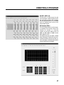
9.5 Crossover Filters:
The Low and High frequencies set the frequency bandwidth for the selected channel of the
crossover. For example, in a three-way
crossover, the Low Band might be 60 Hz to
200Hz; the Mids 200Hz to 1800Hz and the
Highs 1800Hz to 15 kHz.
The different filter types and slopes, including
Bessel, Butterworth, Linkwitz-Reilly and shelving filters with different Q values each offer particular advantages and disadvantages depending on the application and conditions.
27
®
CREATING A PROGRAM
Most analog crossovers use 24 dB/octave, so this is a good place to start.
The window also includes a graphic display that shows the response curve of the currently
selected filters and equalizers in a Level vs. Frequency graph.
Clicking on any of the filter text boxes (lower left of the window) opens a new window called
XOVER. Use the sliders to browse the available filter types and click on the desired one. Use
the horizontal slider to select the corner or “knee” frequency. This is the frequency point at
which a filter begins to attenuate any signal above (for Low Pass) and below (for High Pass)
the selected frequency. The choices are preset in specific increments and ranges that correspond to the selected crossover architecture (2 Way, 3 Way. etc.).
The description of filters as 16dB, 24dB, 48 dB, etc. actually means XX dB PER OCTAVE. A
higher number means a steeper attenuation slope. You can see the different slopes selected
in the graphic display window.
You can use the PEQ to help compensate for dips or peaks at the crossover points. Remember
though that less equalization is better: try to use a combination of slope, filter type and frequency to get the crossover point between bands (for instance: low to mids or mids to highs)
as “flat” as possible. The will minimize the need for additional equalization
Always check the manufacturers specifications for the speakers you are using so the proper
crossover settings can be used, Incorrect settings or mis-wiring (sending lows to a HF driver
for instance) can damage or destroy your equipment. BBE Sound is not liable for any direct
or consequential damages caused by improper use of its equipment.
28
CREATING A PROGRAM
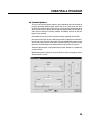
9.6 Parametric Equalizers:
The next set of text boxes provides Frequency, Gain and Q setting choices for five bands of
parametric equalization (PEQ) per output channel. There is also a check box for Flat, which
will bypass the settings for that particular filter. In a similar manner to the Crossover filters
above, clicking on any text box will open the PEQ filter settings window. Use the sliders to
select values for Frequency Q and Gain (cut/boost). An additional check box for FLAT will
bypass all value selections.
At the bottom of the screen are forward and back arrows to step through the five PEQ’s.
Gain must be set to 0 (zero) to select a different type of filter including the Hi or Low Shelf filter. Gain must remain at 0 for the shelving filters. Click the Set 0dB button to move the Gain
slider to 0 dB or move the slider. If Low Shelf is selected and the Gain is moved to a setting
other than 0, the shelving filter will be disabled and the screen functions will “grey out”.
To adjust the gain for Input A, use your pointing device (mouse, touchpad, etc.) to position the
cursor over the box.
NOTE: Whatever program settings are current will be what is saved as the program, unless a
different program is recalled.
29
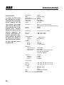
SPECIFICATIONS
®
BALANCED INPUTS
As standard, the DS48 comes
with electronically servo-balanced inputs. This circuit design
features automatic hum and
noise reduction for balanced
signals and thus allows for trouble-free operation even at high
operating levels. Externally
induced mains hum etc. will be
effectively suppressed. The
automatic servo-function recognizes the presence of unbalanced connectors and adjusts
the nominal level internally to
avoid level differences between
the input and output signals
(correction 6 dB).
Input Impedance ………………10KOhms
CMRR …………………………50dB (30Hz~20KHz)
Output Impedance ……………<50Ohms
Maximum output electrical level Vpp=7.6V
Frequency Resp ………………20Hz~20.0KHz
Dynamic Range ………………110dB (A weighted)
Distortion ………………………0.01%(THD)
A/D Processor …………………AK5392; 24 bit data channel, processing
Full 48-bit double-precision mode, 24bit/48khz sample rate
AD latency ……………………0.806MS;
DA latency ……………………0.513MS
Maximum Delay ………………7ms (selectable in .5 ms increments)
Output gain ……………………-40dB~+6dB (+/-0.5dB)
Input gain ……………………-40dB~+6dB (+/-0.5dB)
Parametric Equalizer
Filter Gain ………………+/-12dB in 1dB steps
Center Freq ………………20Hz~20KHz 31 ISO
Q value …………………0.5~10
Shelving
Lo-shelf …………………20Hz~1kHz
Hi-shelf …………………1kHz~20kHz
Shelf gain ………………+/-12dB in 1 dB steps
HPF&LPF Filter
Frequency (high pass) ……<10Hz~16.0kHz
Frequency (low pass) ……35Hz~22.0kHz
Response curve …………Butterworth 6dB, 12dB, 18dB, 24dB, 48dB
Bessel 12dB, 18dB, 24dB, 48dB
Linkwitz-Riley 24dB, 48dB
Limiter Level …………………-40~+3dB
Attack time ………………1~100ms
Holding time ……………0~100ms
Decay time ………………10-1000ms
LCD 2X20 Backlit
Input LED ……………………-30dB, -24dB, -12dB, -6dB, -3dB, Limit, Clip
Output LED ……………………-30dB, -24dB, -12dB, -6dB, -3dB, Limit, Clip
Connectors
Input ……………………XLR-3F (Pin 2 “Hot”)
Output ……………………XLR-3M (Pin 2 “Hot”)
RS232
Power …………………………110VAC 60Hz, 220VAC 50Hz,
Weight ………………………8 lbs (3.6 kg)
Size 19” x 1.74” x 8.66” (80mmX44mmX220mm)
30
SERVICE • WARRANTY • MAINTENANCE
11 SERVICE
We recommend that if at all possible, a BBE DS48 that requires service be sent to our
facility in Huntington Beach, California. We request that a “RETURN AUTHORIZATION” be
issued by the dealer from whom you purchased the unit. If this is not possible, call BBE
Sound, Inc. directly at (714) 897-6766, extension 116 to obtain a “RETURN AUTHORIZATION”. Include a copy of the bill of sale with the unit when it is shipped to BBE Sound, Inc.
so that the service can be expedited.
As the repair turnaround time is minimal, we request that the unit be sent to BBE Sound,
Inc. We also need to add reliability data to our files so that future revisions may be undertaken, if necessary, to improve the product. If unit has been purchased outside the US,
please contact your national distributor.
12 WARRANTY
Warranty registration of the unit to BBE Sound, Inc. is not necessary. It is strongly recommended that you retain a copy of the bill of sale for future reference.
IT IS THE SOLE RESPONSIBILITY OF THE END USER TO PROVIDE THE BILL OF SALE OR
OTHER MEANS OF PROOF OF PURCHASE TO VALIDATE THE WARRANTY IF WARRANTY
SERVICE IS REQUESTED.
The BBE DS48 DIGITAL SPEAKER PROCESSOR is warranted against defects in material
and workmanship for a period of two (2) years from date of purchase from BBE Sound
Inc. or from an authorized dealer. During this period, we will repair units free of charge
providing that they are shipped prepaid to BBE Sound, Inc., 5381 Production Drive,
Huntington Beach, CA 92649. We will pay return UPS shipping charges within the USA. All
charges related to non-UPS shipping, including customs clearance, will be billed. The
warranty will be honored for the longer of either 90 days from the date of any service or
the remainder of the original 2 Year factory warranty. This warranty will be considered null
and void by BBE Sound, Inc. if any of the following is found:
1. The equipment has been physically damaged.
2. The equipment shows signs of abuse.
3. The equipment has been electrically damaged by improper connection
or attempted repair by the customer or unauthorized third party.
4. The equipment has been modified without authorization.
5. The bill of sales indicates that the purchase date of the equipment
31
®
SERVICE • WARRANTY • MAINTENANCE
is not within the warranty period.
All non-warranty repairs are warranted for a period of 90 days from the date of service.
BBE Sound, Inc. is NOT LIABLE FOR CONSEQUENTIAL DAMAGES. Should the unit fail to
operate for any reason, our sole obligation is to repair it as described above.
DO NOT RETURN ANY PRODUCT TO THE ABOVE ADDRESS WITHOUT INSTRUCTIONS AND
AUTHORIZATION ISSUED BY THE ABOVE LOCATION.
13 MAINTENANCE
Maintenance of the BBE DIGITAL SPEAKER PROCESSOR is limited to proper cleaning of
the unit with mild household cleaner such as Formula 409™ or Windex™. The chassis
and cover are steel finished with a durable polyurethane paint, while the front panel is
an anodized aluminum extrusion. There are no user replaceable parts and the unit
should not be opened for any reason unless you are a qualified technician.
Calibration should be performed if parts are replaced or if a performance check-out
indicates a problem with calibration. Long term use has shown that over the life of this
unit there is little or no drift of the components in the BBE DIGITAL SPEAKER PROCESSOR that would cause a change in calibration. A very conservative design philosophy
has resulted in a piece of equipment which runs very cool and should give years of trouble-free service.
32
®
5381 Production Drive
Huntington Beach, CA 92649
714-897-6766 • FAX 714-896-0736
www.bbesound .com
BBE is the registered trademark of BBE Sound, Inc.
rev. 1 3/2006