1
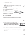
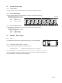
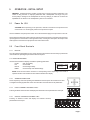
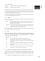
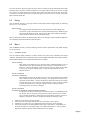
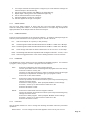
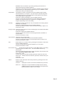
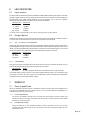
UX3600
D I G I TA L S I G N A L P R O C E S S O R / C R O S S O V E R
OWNER’S MANUAL
1
INPUTS
A
USB
B
C
Clip
-6
-12
Clip
-6
-12
Clip
-6
-12
Sig
Sig
Sig
MUTE
MUTE
UX 3600 Speaker / System Processor
System Menu
Channel Setup
Xover Setup
MUTE
OUTPUTS
LEVEL
MENU
LIM
OK
PROG
UTIL
3
2
1
4
5
6
Clip
Lim
-12
Clip
Lim
-12
Clip
Lim
-12
Clip
Lim
-12
Clip
Lim
-12
Clip
Lim
-12
Sig
Sig
Sig
Sig
Sig
Sig
MUTE
MUTE
MUTE
MUTE
MUTE
MUTE
Page ii
1. IMPORTANT SAFETY INSTRUCTIONS
1.
Read these instructions.
2.
Keep these instructions.
3.
Heed all warnings.
4.
Follow all instructions.
5.
Do not use this apparatus near water.
6.
Clean only with dry cloth.
7. Do not block any ventilation openings. Install in accordance with
the manufacturer's instructions.
15. This apparatus shall not be exposed to dripping or splashing. And no
object filled with liquid such as vases, shall be place on the apparatus.
16. Do not overload wall outlets and extension cords as this can result in
a risk of fire or electric shock.
17. This apparatus has been designed with Class-I construction and
must be connected to a mains socket outlet with a protective earthing
connection (the third grounding prong).
18. This apparatus has been equipped with a rocker-style AC mains
power switch. This switch is located on the rear panel and should
remain readily accessible to the user.
8.
Do not install near any heat sources such as radiators, heat registers,
stoves, or other apparatus (including amplifiers) that produce heat.
19. The mains plug or an appliance coupler is used as the disconnect
device, so the disconnect device shall remain readily operable.
9.
Do not defeat the safety purpose of the polarized or groundingtype plug. A polarized plug has two blades with one wider than the
other. A grounding type plug has two blades and a third grounding
prong. The wide blade or the third prong are provided for your
safety. If the provided plug does not fit into your outlet, consult an
electrician for replacement of the obsolete outlet.
20. NOTE: This equipment has been tested and found to comply with
the limits for a Class A, digital device, pursuant to Part 15 of the FCC
Rules, and the rules for Canada under ICES-003 - Feb 04. These
limits are designed to provide reasonable protection against harmful
interference when the equipment is operated in a commercial
environment. This equipment generates, uses, and can radiate radio
frequency energy and, if not installed and used in accordance with
the instruction manual, may cause harmful interference to radio
communications. Operation of this equipment in a residential area is
likely to cause harmful interference in which case the user will be
required to correct the interference at his/her own expense.
10. Protect the power cord from being walked on or pinched
particularly at plugs, convenience receptacles, and the point where
they exit from the apparatus.
11. Only use attachments/accessories specified by the manufacturer.
12. Use only with the cart, stand, tripod, bracket,
or table specified by the manufacturer, or sold
with the apparatus. When a cart is used, use
caution when moving the cart/apparatus
combination to avoid injury from tip-over.
CAUTION: Changes or modifications to this device not expressly
approved by LOUD Technologies Inc. could void the user’s authority
to operate the equipment under FCC rules.
13. Unplug this apparatus during lightning storms
or when unused for long periods of time.
14. Refer all servicing to qualified service
personnel. Servicing is required when the
apparatus has been damaged in any way, such as power-supply
cord or plug is damaged, liquid has been spilled or objects have fallen
into the apparatus, the apparatus has been exposed to rain or
moisture, does not operate normally, or has been dropped.
UX3600
Page iii
1.2
Declaration of Conformity
(Please see below for the list of standards)
European Council Directive on Low Voltage, 2006/95/EC
European Council Directive on Electromagnetic Compatibility, 2004/108/EC
EN60065:2002+A1:2006+A11:2008 Audio, video, and similar electronic apparatus – safety
requirements
EN55103-1:2009 Emissions standard for audio, video, audio-visual and entertainment
apparatus for professional use
EN55103-2:2009 Immunity standard for audio, video, audio-visual and entertainment
apparatus for professional use
Page iv
CONTENTS
1
1.2
2
2.1
2.2
2.3
3
3.1
3.2
3.4
3.5
4
4.1
4.2
4.3
4.4
5
5.1
5.2
5.3
5.4
5.5
5.6
6
6.1
6.2
7
7.1
8
8.1
8.2
8.3
8.4
9
10
IMPORTANT SAFETY INSTRUCTIONS . . . . . . . . . . . . . . . . . . . . . . . . . . . . . . . . .iii
Declaration of Conformity . . . . . . . . . . . . . . . . . . . . . . . . . . . . . . . . . . . . . . . . . . . .iv
CONTENTS . . . . . . . . . . . . . . . . . . . . . . . . . . . . . . . . . . . . . . . . . . . . . . . . . . . . . . .1
UNPACKING . . . . . . . . . . . . . . . . . . . . . . . . . . . . . . . . . . . . . . . . . . . . . . . . . . . . . .2
Contents . . . . . . . . . . . . . . . . . . . . . . . . . . . . . . . . . . . . . . . . . . . . . . . . . . . . . . . . .2
Shipping Damage . . . . . . . . . . . . . . . . . . . . . . . . . . . . . . . . . . . . . . . . . . . . . . . . . .2
Returning a Processor to EAW . . . . . . . . . . . . . . . . . . . . . . . . . . . . . . . . . . . . . . . .2
INTRODUCTION . . . . . . . . . . . . . . . . . . . . . . . . . . . . . . . . . . . . . . . . . . . . . . . . . . .3
UX3600 Description . . . . . . . . . . . . . . . . . . . . . . . . . . . . . . . . . . . . . . . . . . . . . . . .3
Features and Benefits . . . . . . . . . . . . . . . . . . . . . . . . . . . . . . . . . . . . . . . . . . . . . . .3
Front Panel . . . . . . . . . . . . . . . . . . . . . . . . . . . . . . . . . . . . . . . . . . . . . . . . . . . . . . .4
Rear Panel . . . . . . . . . . . . . . . . . . . . . . . . . . . . . . . . . . . . . . . . . . . . . . . . . . . . . . .4
UX3600 INSTALLATION . . . . . . . . . . . . . . . . . . . . . . . . . . . . . . . . . . . . . . . . . . . . .5
Physical Installation . . . . . . . . . . . . . . . . . . . . . . . . . . . . . . . . . . . . . . . . . . . . . . . . .5
AC Mains Connections . . . . . . . . . . . . . . . . . . . . . . . . . . . . . . . . . . . . . . . . . . . . . .5
Audio Connections . . . . . . . . . . . . . . . . . . . . . . . . . . . . . . . . . . . . . . . . . . . . . . . . .6
Network Connections . . . . . . . . . . . . . . . . . . . . . . . . . . . . . . . . . . . . . . . . . . . . . . .6
OPERATION - INITIAL SETUP . . . . . . . . . . . . . . . . . . . . . . . . . . . . . . . . . . . . . . . .7
Power On /Off . . . . . . . . . . . . . . . . . . . . . . . . . . . . . . . . . . . . . . . . . . . . . . . . . . . . .7
Front Panel Controls . . . . . . . . . . . . . . . . . . . . . . . . . . . . . . . . . . . . . . . . . . . . . . . .7
Level . . . . . . . . . . . . . . . . . . . . . . . . . . . . . . . . . . . . . . . . . . . . . . . . . . . . . . . . . . . .8
EQ . . . . . . . . . . . . . . . . . . . . . . . . . . . . . . . . . . . . . . . . . . . . . . . . . . . . . . . . . . . . . .8
Delay . . . . . . . . . . . . . . . . . . . . . . . . . . . . . . . . . . . . . . . . . . . . . . . . . . . . . . . . . . . .9
Menu . . . . . . . . . . . . . . . . . . . . . . . . . . . . . . . . . . . . . . . . . . . . . . . . . . . . . . . . . . . .9
LED INDICATORS . . . . . . . . . . . . . . . . . . . . . . . . . . . . . . . . . . . . . . . . . . . . . . . . . .12
Input Meters . . . . . . . . . . . . . . . . . . . . . . . . . . . . . . . . . . . . . . . . . . . . . . . . . . . . . .12
Output Meters . . . . . . . . . . . . . . . . . . . . . . . . . . . . . . . . . . . . . . . . . . . . . . . . . . . .12
EAWPILOT . . . . . . . . . . . . . . . . . . . . . . . . . . . . . . . . . . . . . . . . . . . . . . . . . . . . . . .12
Extra Capabilities . . . . . . . . . . . . . . . . . . . . . . . . . . . . . . . . . . . . . . . . . . . . . . . . . .12
MAINTENANCE AND SERVICE . . . . . . . . . . . . . . . . . . . . . . . . . . . . . . . . . . . . . . .13
Maintenance . . . . . . . . . . . . . . . . . . . . . . . . . . . . . . . . . . . . . . . . . . . . . . . . . . . . . .13
Service . . . . . . . . . . . . . . . . . . . . . . . . . . . . . . . . . . . . . . . . . . . . . . . . . . . . . . . . . .13
Return and Repair Issues . . . . . . . . . . . . . . . . . . . . . . . . . . . . . . . . . . . . . . . . . . . .13
How to Contact EAW . . . . . . . . . . . . . . . . . . . . . . . . . . . . . . . . . . . . . . . . . . . . . . . .13
TROUBLESHOOTING . . . . . . . . . . . . . . . . . . . . . . . . . . . . . . . . . . . . . . . . . . . . . .14
BLOCK DIAGRAM . . . . . . . . . . . . . . . . . . . . . . . . . . . . . . . . . . . . . . . . . . . . . . . . .15
Page 1
2
UNPACKING
2.1
Contents
1
1 set
1
1
1
1
2.2
UX3600 Digital Processor
Internal support packaging
IEC Power cable 6 ft / 2 m with Nema 15-3 ac mains plug for 115V / 120 V
IEC Power cable 6 ft / 2 m with Schuko type ac mains plug for 220 V / 240 V
UX3600 Owner’s Manual (this document)
Product registration instructions
Shipping Damage
If you find the processor is damaged after unpacking, save the packing materials for the carrier’s
inspection, notify the carrier immediately, and file a shipping damage claim. Although EAW will help in
any way possible, it is always the responsibility of the receiving party to file any shipping damage claim.
The carrier will help prepare and file this claim.
2.3
R e t u r n i n g a P r o c e s s o r t o E AW
If the processor must be returned, contact EAW for a Return Authorization. Use the original shipping
carton and packing materials. If the shipping carton is damaged, contact EAW for a new carton at a
nominal charge. EAW will not be responsible for damage caused by inadequate packing.
Page 2
3
INTRODUCTION
Congratulations on purchasing the innovative UX3600 digital signal processor (DSP) from Eastern
Acoustic Works. While designed with the fundamental principles of close-coupled processing used
since the first MX Series Processors in the 1980s, the UX3600 uses EAW’s latest advances in digital
technology to provide optimum signal processing and management of EAW loudspeaker systems.
3.1
UX3600 Description
The UX3600 is a 3-input, 6-output digital signal processor.
It functions as a user-controlled, digital signal processor, as well as providing sophisticated,
EAW-engineered digital processing for specific portable and installed EAW loudspeakers.
Processing tools include 10 EQ filters and signal delay (up to 1200 ms) for each input and output,as
well as gain, polarity, limiting, and crossover filters.
One can set up multiple processors for specific EAW loudspeaker products or loudspeaker arrays.
These pre-programed loudspeaker settings are referred to as “Greyboxes.” This term comes from
certain parameters not being user adjustable (“black-boxed”), certain parameters being user
adjustable (“white-boxed,” as it were), with the combination of black/white being grey. Greybox
settings consist of preset, EAW-engineered processing parameters for the crossovers, equalization,
limiting, and other settings as an integral part of that loudspeaker’s design and operation. These
settings include EAW’s digital processing invention called EAW Focusing™. In addition, preset limiting
parameters are designed to maximize sonic performance during active limiting while providing robust
driver protection. These preset parameters are locked down to prevent inadvertent or purposeful
modifications. However, the user retains control of gain, input EQ, signal delay, and polarity for each
Greybox loudspeaker.
The simplicity of the UX3600 is practical for entry level users and fast to operate for professional users.
This function provides for a high level of system consistency while retaining all necessary user
alignment controls.
3.2
Features and Benefits
•
“Greybox” operation – Complete processing presets for EAW loudspeakers provides ease
of setup, consistency, and interoperability between EAW products and systems.
•
Comprehensive and intuitive front panel control – Access to operational parameters
making computer control unnecessary for simple and quick adjustments.
•
EAWPilot software – Comprehensive software control of all hardware parameters.
•
EAW Focusing capable – Implements EAW Focusing for specific EAW loudspeaker
systems using the “Greybox” mode.
•
All filter parameters are compatible with EAW’s measurement and modeling software - Allows
the creation of advanced array processing.
•
Advanced Greybox Limiting - Provides more robust driver protection and better sonic
performance based on specific EAW driver and loudspeaker performance characteristics.
Page 3
3.4
Front Panel
2
A
Clip
-6
-12
USB
Sig
3
UX 3600 Speaker / System Processor
C
OK
DELAY
MUTE
MENU
4
6
5
3
2
1
EQ
Channel Setup
Xover Setup
Sig
MUTE
OUTPUTS
LEVEL
MENU
System Menu
Clip
-6
-12
Sig
MUTE
1
B
Clip
-6
-12
8
7
INPUTS
4
6
5
Clip
Lim
-12
Clip
Lim
-12
Clip
Lim
-12
Clip
Lim
-12
Clip
Lim
-12
Clip
Lim
-12
Sig
Sig
Sig
Sig
Sig
Sig
MUTE
MUTE
9
10
MUTE
MUTE
MUTE
MUTE
S
3.5
1. USB
For connection to a PC running EAWPilot.
2. Input Channels A to C
Selects the input channel for display of or editing its parameters selected by a
Function button.
3. Input Channel Meters
Provides input metering after the ADC (analog to digital converter).
4. Input Channel Mutes
Mutes the output signal of the corresponding input channel.
5. LCD Display
Displays parameters for function selected by the function buttons.
6. Arrows & OK Buttons
Control for navigating menus and changing parameter settings.
7. Function Buttons
Selects the function to be displayed or edited in the LCD display.
8. Output Channels 1 to 6
Selects the output channel for display of or editing its parameters selected by a
Function button.
9. Output Channel Meters
Provides output metering before the DAC (digital to analog converter).
10. Output Channel Mutes
Mutes the signal of the corresponding output channel.
M
Rear Panel
~100-240 VAC
50-60Hz 75W
12
6
I
O
5
OUTPUTS
4
3
2
1
PUSH
ANALOG
13
14
12. IEC Receptacle
AC Mains input, 100 V to 240 V, 50 Hz to 60 Hz.
13. Power Switch
AC Mains on and off.
14. Outputs 1 to 6
XLR connectors for audio outputs (analog).
15. Inputs A to C
XLR connectors for audio inputs (analog).
C
INPUTS
PUSH
ANALOG
B
PUSH
A
ANALOG
15
Page 4
4
UX3600 INSTALLATION
4.1
Physical Installation
CAUTION: The UX3600’s operating temperature range is 32 F to 104 F degrees / 0 C to 40 C
degrees. The UX3600 may not function properly in temperatures below this range and may be
damaged in temperatures above this range.
4.1.1
MOUNTING
The UX3600 is designed to mount in a standard, 19 in equipment rack occupying one EIA rack space
(1.75 in). When rack mounting, use screws with mating plastic washers to help protect the finish of the
UX3600. The UX3600 weighs approximately 9.5 lb / 4.3 kg.
4.1.2
VENTILATION
Side ventilation holes on the UX3600 should be left
unobstructed when installed.
MAINTAIN 1 in [25 mm] CLEARANCE
AROUND SIDE
AIR INTAKE
GRILLES
It is recommended to leave one empty rack space above
the UX3600 to provide 1.75 in / 45 mm clearance above
the top.
4.2
AC M a i n s C o n n e c t i o n s
4.2.1
AC MAINS VOLTAGE
MAINTAIN
1 in [25 mm] CLEARANCE
AROUND SIDE AIR INTAKE GRILLES
VENTILATION CLEARANCES
The UX3600 has a universal, auto-ranging power supply that operates from 100 V to 240 V, 50 Hz to 60
Hz. The UX3600 is compatible with these nominal AC Mains:
100 V, 110 V, 115 V, 120 V, 127 V, 220 V, 230 V, and 240 V at 50 Hz to 60 Hz.
CAUTION: To maintain compliance ratings, keep the AC Mains voltage between 100 V to 240 V.
4.2.2
IEC POWER CORD RECEPTACLE
An IEC-320 AC Mains inlet on the rear panel accepts the detachable power cords supplied with the
unit. Use the power cord appropriate for these nominal AC Mains supply voltages.
120 V AC Mains: use the power cord with the NEMA 5-15 plug, EAW part # 640-01-00
220 V AC Mains: use the power cord with the Schuko plug, EAW part # 640-02-02
CAUTION: It is the user’s responsibility to provide a proper AC Mains plug for any
AC Mains outlet configuration that differs from those supplied with the product.
4.2.3
~100-240 VAC
50-60Hz 75W
I
O
GROUNDING
The chassis of this product is grounded through the grounding conductor of the power cord. To avoid
electric shock, plug the power cord into a properly wired and grounded receptacle before making any
connections to or operating the product.
DANGER: This equipment must be operated with the power cord grounding conductor
connected to a properly grounded AC outlet. Do not disconnect, “lift,” or otherwise remove this
ground connection. Without this connection, accessible parts, including knobs and controls that
may appear to be insulated, can render an electric shock that can cause injury or death to
operating personnel.
Page 5
4.3
Audio Connections
4.3.1
SIGNAL CABLE
Use a good quality, 2-conductor shielded cable for all audio input and output connections.
4.3.2
INPUT CONNECTIONS
The three, female, XLR-type connectors labeled A through C are audio input connectors.
Analog Pin-Out: XLR A to XLR C
1 SHIELD
Electronically balanced, line level
Pin 1: Shield
OUTPUTS
4
5
3
6
2
Pin 2: + (plus or high)
Pin 3: - (minus or low)
1 SIGNAL EARTH
(CABLE SHIELD)
1
PUSH
C
OUTPUT CONNECTIONS
3-
2+
2+
3-
PUSH
A NALOG
ANALOG
4.3.3
INPUTS
1 SHIELD
B
PUSH
A
ANALOG
2 SIGNAL
3 SIGNAL
The six, male, XLR-type connectors labeled 1 through 6 are the audio output connectors.
Analog: XLR 1 to XLR 6
Electronically balanced, line level.
Pin 1: shield
Pin 2: + (plus or high)
Pin 3: - (minus or low)
4.4
Network Connections
4.4.1
USB
The UX3600 communicates with a computer through its built-in, front panel, USB port.
A
Clip
-6
-12
USB
Sig
4.4.8
SOFTWARE INSTALLATION -- EAWPILOT
MUTE
EAWPilot requires an IBM compatible PC equipped as follows:
Operating System:
Windows Vista, XP, 2000, NT, ME, or Windows 7
The latest EAWPilot can be downloaded from the EAW web site: www.eaw.com. Go to the
“Downloads” page. Once installed and with the computer connected to the UX3600, open EAWPilot by
clicking on EAWPilot in the Start/Programs/EAW/EAWPilot.
Page 6
5
OPERATION - INITIAL SETUP
WARNING: A digital processor provides a wide range of signal processing parameters. The
results of using incorrect or improper parameters with a loudspeaker can range from poor
sound quality to damage to the loudspeaker. Be sure any settings you make do not cause the
capabilities of the drivers in the loudspeaker system to be exceeded.
5.1
Po w e r O n / O f f
CAUTION: Before powering on the processor, make all connections to the processor and
ensure there is no audio signal present at the processor’s inputs.
Use the UX3600’s rear panel power switch to turn the AC Mains supply to the processor on and off.
Always follow prudent audio system practices and procedures for powering on equipment by powering
up all equipment in the direction of the signal flow order, meaning from the input to the output of the
audio system. Power down the equipment in the reverse of this order.
5.2
Front Panel Controls
5.2.1
DISPLAY
The LCD (liquid crystal display) screen, along with the function buttons and arrow keys provides the
user interface for operating the processor from the front panel.
5.2.2 FUNCTION BUTTONS
Use the function buttons to display and edit the operating parameters.
LEVEL
Gain and polarity
EQ
Channel EQ
DELAY
Channel signal delay
MENU
Channel setup and Global settings
UX 3600 Speaker / System Processor
System Menu
LEVEL
MENU
EQ
Channel Setup
Xover Setup
OK
DELAY
MENU
NOTE: Some function buttons will have no corresponding screen depending on the mode of
operation and the channel selected. This will be indicated in the display.
5.2.3
ARROW BUTTONS & OK
This is the primary control for operating the UX3600 from the front panel. Arrow buttons are used
to navigate and change parameter values. The OK button is used to select or set parameters.
5.2.4
INPUT CHANNELS: BUTTONS A TO C
INPUTS
A
Pressing an INPUT channel button will display the selected function’s parameters for this input.
Clip
-6
-12
Sig
C
Clip
-6
-12
Sig
MUTE
5.2.5
B
Clip
-6
-12
Sig
MUTE
MUTE
OUTPUT CHANNELS: BUTTONS 1 TO 6
Pressing an OUTPUT button will display the selected function’s
parameters for this output.
OUTPUTS
L
G
L
3
2
1
4
6
5
Clip
Lim
-12
Clip
Lim
-12
Clip
Lim
-12
Clip
Lim
-12
Clip
Lim
-12
Clip
Lim
-12
Sig
Sig
Sig
Sig
Sig
Sig
MUTE
MUTE
MUTE
MUTE
MUTE
MUTE
Page 7
5.2.6
OUTPUTS
MUTE BUTTONS
Input Mutes:
Output Mutes:
Mutes the output signal of the corresponding Input Channel.
3
2
1
4
Clip
Lim
-12
Clip
Lim
-12
Clip
Lim
-12
Clip
Lim
-12
Sig
Sig
Sig
Sig
Sig
Mutes the signal to the output XLR.
MUTE
MUTE
MUTE
MUTE
When a channel is muted the top two segments of the corresponding meter will be illuminated.
Mute settings are not saved with and therefore not recalled from Program files saved in the processor’s
memories. However, the behavior of the mutes may be changed when a program is recalled according
to the Program Load setting made in the UTIL menus.
In contrast, mute settings are saved as part of EAWPilot files (*.ept files) and are uploaded to the
processor as part of the settings stored in those files.
5.3
Level
Use the LEVEL function to set Input Channel or Output Channel gain and Polarity by selecting
the A to C or 1 to 6 buttons.
GAIN:
To change the gain parameter use the OK button to select and use the up or
down arrow button to scroll by 0.1dB steps +/- 15dB. Press OK when
finished to enter selected gain.
POLARITY: To change the POLARITY parameter use the OK button to select and use the
up or down arrow buttons to switch between Normal and Inverted polarity.
Press OK when finished to enter selected polarity.
When a Greybox has been loaded changes made to one Greybox output leg will be applied to
all output legs associated with the same Greybox.
5.4
EQ
Use the EQ function to set the Input Channel EQ and Output channel EQ (EQ is disabled for
outputs tied to a Greybox) by selecting the A to C or 1 to 6 buttons. Each channel’s EQ section
has 10 filters. Each EQ section has the following variable parameters. The available
parameters depend on the selected type.
Parametric
EQ:
Sets the entire EQ section to In (active) or Out (inactive).
Type:
Scroll through and select the type for each filter: Bell, 6 dB LoShelf,
12 dB LoShelf, 6 dB HiShelf, 12 dB HiShelf, 6 dB HPF, 12 dB HPF, 6 dB LPF,
or 12 dB LPF.
BW:
Scroll through and select the bandwidth for each filter:0.02 to 10 octaves.
Freq:
Scroll through and select the frequency for each filter : 20Hz to 20k, 1/24th
octave steps.
Gain:
Scroll through and select the gain for each filter: +/- 15dB in 0.1dB steps
Filt:
Sets the filter (1 to 10) to In (active) or Out (inactive)
5.4.1
TURNING ALL PARAMETRIC EQ ON OR OFF FOR A SELECTED CHANNEL
From the EQ menu use the right arrow key to select the In/Out parameter. Use the up or down
arrow key to select In or Out. To set parameters for an individual filter press the right arrow
button. To set parametric EQ In or Out without moving into individual filters press the OK
button.
5.4.2
5
Clip
Lim
-12
SETTING FILTER PARAMETERS FOR AN INDIVIDUAL FILTER (1 THROUGH 10)
Page 8
MU
From the EQ menu press the right arrow key twice to step through the Parametric EQ In/Out
selection field. The filter number will appear on the upper right corner of the LCD (1 through
10). Use the up and down arrows to set the Type, BW, Freq, Gain, and Flt for any given filter.
To advance to another filter press and hold the right or left arrow key for at least 2 seconds.
When finished press OK.
5.5
Delay
Use the DELAY function to set Input Channel and Output Channel signal delay by selecting
the A to C or 1 to 6 buttons.
INPUT DELAY:
To change the DELAY parameter use the OK button to select Delay and
use the left or right arrow buttons to choose millisecond (ms) or distance input
and use the OK button to select. Use the up or down arrow buttons to set delay.
Press OK when finished to enter selected delay.
When a Greybox has been loaded changes made to one Greybox output leg will be applied to
all output legs associated with the same Greybox.
5.6
Menu
Use the MENU function to setup remaining channel specific parameters and global settings
for the processor.
5.6.1
CHANNEL SETUP
Use the Channel Setup submenu to select Sources and name Input Channels and Output
Channels. Use this feature to view Greybox type, enter amplifier information into Greybox limiters,
and set listener distance into Output Channels tied to a Greybox.
INPUT SOURCE:
Each input can be fed from one or the sum of two combined Analog inputs. To
change Source use the up and down arrow buttons to choose Source 1 or
Source 2. Use the OK button to select and use the up or down arrow button
to set one of the three Analog inputs. Press OK when finished to enter
selected Source.
OUTPUT SOURCE
(WITHOUT GREYBOX):
Each Output Channel can be fed from one of the Input Channels and loaded
with a Greybox from the processors memory. To change Source use the up
and down arrow buttons. Use the OK button to select and use the up or down
arrow button to set one of the three Input Channels. Press O when finished
to enter selected Source. The type of Output Source is always System
Processing when not tied to a Greybox.
OUTPUT SOURCE
(LOADING A GREYBOX FROM INTERNAL MEMORY):
If a Greybox has been stored to the processors memory from EAWPilot it can
be used to drive an output by using the up and down arrow keys to choose
Type. Use the OK button to select and the up and down arrows to choose a
Greybox. Greyboxes are then configured through the following steps:
1.
2.
3.
4.
Select an Input Source for the Greybox.
Choose Yes to reset Input DSP for use with a Greybox or No to abort.
Assuming you chose Yes, set a High Pass Filter Frequency for the Greybox.
Choose an output for the designated Greybox leg (a leg refers to a bandpass in a
multi-amp Greybox or full range output of a single-amp Greybox). The leg will be
displayed under the Output Channel Selection on the display.
Page 9
5.
If an Output Channel has already been configured you will be asked to reassign the
selected Output to the selected leg.
6. Set the Amp Gain and Amp Volts RMS for the associated leg.
7. Repeat steps 4 through 6 for each additional Greybox leg.
8. Set the Listener Distance for the Greybox.
9. Set Delay applied to all legs of a Greybox.
10. Set Gain applied to all legs of a Greybox.
5.6.2
XOVER SETUP
Use the Xover Setup submenu to select High and Low Pass Filters applied to Output
Channels. Setting Pass Filters on an Output Channel tied to a Greybox leg will adjust the
appropriate filters for all Output Channels tied to the Greybox.
5.6.3
COMP/LIM SETUP
Press OK to select parameter for the Comp/Lim submenu. To advance vertically through the
submenu press and hold the left or right arrow key for at least 2 seconds.
Lim:
Sets the Comp/Lim to In (active) or Out (inactive)
Atk:
Scroll through and select the limiter threshold from 20 dBu to -10 dBu in 0.1 dB steps.
Thrsh: Scroll through and select the limiter threshold from 20 dBu to -10 dBu in 0.1 dB steps.
Rel:
.
Scroll through and select the limiter release from 10 ms to 2 Sec in 10 ms steps.
Ratio: Scroll through and select the compression ratio in integer increments: 1:1 to 20:1, or Inf:1
Knee: Select the aggressiveness of the onset of limiting between a hard or soft knee.
5.6.4
PROGRAM
The UX3600 has memory spaces for 50 user-savable and loadable programs. You can Save
a program, Load a program, or Delete a program from this submenu.
.
Save
Press Ok to select Save from the Program submenu.
Use the up and down arrow to scroll through the 50 program slots in the memory.
Press Ok to select a memory slot.
Using the up and down arrow keys to select a character and the left and right
arrow keys to step between characters give your program a name.
Press enter to save when finished
Load:
Press OK to select Load from the Program submenu.
Use the up and down arrow buttons to select a previously stored setting if any
settings have been stored.
Press OK to select program. When prompted “Modifies current settings.
Proceed?”, use the up or down arrows to select Yes or No.
Press the OK button to enter.
Press the OK button to enter.
Delete:
Press OK to select Delete from the Program submenu.
Use the up and down arrow buttons to select a previously stored setting if any
settings have been stored.
Press OK to delete program. When prompted “Modifies current settings.
Proceed?”, use the up or down arrows to select Yes or No.
Press the OK button to enter.
5.6.5
UTILITIES
Use the utilities submenu to view or change the following information about the processors
operations:
Device Name:
You can change the name that appears on the LCD of your UX or in
Page 10
EAWPilot when connected to your UX by pressing the OK button to
select Device from the Utilities submenu.
Using the up and down arrow keys to select a character and the left and
right arrow keys to step between characters give your UX3600 a name.
Press OK to enter your selected name.
Temperature:
Temperature is used to calculate air loss pre-emphasis when setting
listener distances in a Greybox. It is also used to calculate delay time
from distance which is in turn dependent on the speed of sound which
varies depending on temperature.
Press Ok to select Temperature from the Utilities submenu.
Use the up and down arrow buttons to set the ambient temperature
between 32 F degrees and 104 F degrees or 0 C degrees to 40 C
degrees, depending on the Units setting.
Humidity:
Humidity is used to calculate air loss pre-emphasis when setting listener
distances in a Greybox.
Press Ok to select Humidity form the Utilities submenu.
Use the up and down arrows to enter the relative humidity in steps of 1%.
Press OK to enter.
On Pgrm Load: Select the mute options for when a saved program is recalled and loaded
into active memory.
Press Ok to select from Utilities submenu.
Use the up and down arrows to scroll through No Mutes, All Mutes, or
Current Mutes.
Press the OK button to enter.
LCD Contrast:
Adjust the LCD contrast value.
Press Ok to select LCD Contrast from the Utilities submenu.
Use the up and down arrows to scroll through percent by steps of 1%.
Press the OK button to enter.
Unit:
Select either U.S. or metric units by pressing the OK button to select Unit
from the Utilities submenu.
Use the up and down arrow buttons between U.S. and metric.
Press the OK button to enter.
Front Panel Lock…
To lock the front panel functions, except Mute buttons, from being
operated select Front Panel Lock… from the Utilities submenu by
pressing OK.
Use the up and down arrow keys to enter characters into the pass code
area. The factory default code is 1234.
Press OK to enter.
To set a new pass code after selecting Set Pass Code from the Front
Panel Lock… submenu enter the old code, press OK, and then enter your
new code.
Press OK to enter.
About…
Select to view information about the processor by pressing Ok from the
Utilities submenu.
Version #:
Displays the version of firmware installed in the processor.
Device Id:
Displays the unique hardware ID assigned at the factory.
EAWPilot uses the device ID to identify and recognize each
particular device to which it can connect.
Page 11
6
LED INDICATORS
6.1
Input meters
The input meters indicate the signal level in dB below 0 dBFS (0 dB Full Scale), the clip level of the ADC
(analog to digital converter). An input meter still functions when its Input Channel is muted. Ideally, the
highest levels of the signal should illuminate the -6 LED segment, but not the CLIP segment.
Occasional flashing of the CLIP segment may be sonically acceptable.
LED Segment
Signal Level
Clip Red
0 dBFS
- 6 Yellow
-6 dBFS
-12 Green
-12 dBFS
Sig Green
-40 dBFS
An active mute is indicated when the top two LED segments are illuminated.
6.2
Output Meters
Unlike the input meters, the four LED segments of each output meter make up two different meters.
An active mute is indicated when the top two LED segments are illuminated.
6.2.1
SIG, -12, AND CLIP SIG SEGMENTS
These three segments monitor the signal level in dB below 0 dBFS (0 dB Full Scale), the clip level of
the DAC (digital to analog converter). An output meter still functions when its Output Channel is muted.
Ideally, you want the highest level to illuminate the -12 segment, but not the CLIP segment. You can set
levels lower than this, but understand that you are reducing the signal-to-noise ratio.
LED Segment
Signal Level
Clip Red
0 dBFS
-12 Green
-12 dBFS
Sig Green
-40 dBFS
6.2.2
LIM SEGMENT
This segment monitors the limiter status referenced to the level set for the limiter threshold. The Lim
segment will indicate limiting even when its Output Channel is muted.
LED Segment
Status
Lim Yellow
On when the limiter threshold is exceeded and there is gain reduction
Occasional flashing is OK. However, if the LED is rapidly flashing yellow or is on steadily a large
percentage of the time, the input signal to the loudspeaker may be exceeding the loudspeaker’s
capability and the volume level should be reduced.
7
EAWPILOT
7.1
Extra Capabilities
While the UX3600 interface window in EAWPilot software provides the same capabilities for
controlling the UX3600 as its front panel controls, it also provides additional capabilities not
available using the front panel controls.
7.1.1
LEVEL MONITORING
The meters in EAWPilot provide more accurate and much higher resolution signal level
monitoring. Both the average and peak levels are easier to read and provide mush better
tracking for critical situations.
7.1.2
PARAMETER LINKING
Using the Map tab in the UX3600 interface window, parameter values for the input
channels and the output channels may be linked so that any changes will affect all such
linked parameters.
Page 12
8
MAINTENANCE AND SERVICE
8.1
Maintenance
The only routine and periodic maintenance for the processor is physical cleaning and
performance testing.
8.1.1
CLEANING
Clean the exterior surfaces of the chassis as required, using a soft, dry cloth to remove any dust
or dirt. Remove any dirt from the air intake holes on the side and top of the chassis. Remove any
dirt accumulated on the ventilation fan grille.
CAUTION: To avoid damaging the exterior finishes or internal circuitry do not use any
liquid, cleaning solvents, or abrasives.
While the interval between cleanings will depend on the frequency of usage and the conditions
of use, it is recommended that cleaning be performed at least once a year. Clean more often if
used in dusty or dirty conditions, such as part of a portable or touring system.
8.1.2
PERFORMANCE TESTING
Perform listening tests and/or formal measurements, checking all processor functions for proper operation.
While the interval between testing will depend on the frequency of usage and the conditions of
use, it is recommended that should be performed at least once every six months. Test more often
if used in conditions that subject the unit to mechanical stress, such as part of a portable or
touring system.
8.2
Service
There are no user serviceable parts inside the UX3600 processor. In case of failure, refer all
servicing to the factory. Service and repair information may be obtained by contacting the EAW
Service Department or the EAW distributor for your country.
8.3
Return and Repair Issues
UX3600 repairs can be done either through an EAW distributor, EAW authorized service center,
or by shipping the product to EAW Service. Prior to returning any product to EAW, an RA (Return
Authorization) issued by EAW is required. Contact the EAW Service Department for details.
8.4
H o w To C o n t a c t E AW
We have tried to answer most questions you may have about the UX8800 in this manual. Should
you need further assistance, please do not hesitate to contact us. You can contact EAW in
several different ways:
GENERAL AND APPLICATION SUPPORT GROUP
Eastern Acoustic Works
Tel
800 992 5013
One Main Street
Tel
+1 508 234 6158
Whitinsville, MA 01588 USA
Fax
+1 508 234 8251
Fax
800 322 8251
Web Site
www.eaw.com
SERVICE
EAW Service Department
Building #11
One Main Street
Whitinsville, MA 01588 USA
E-MAIL
General information
Applications Support Group
Service
Tel
Tel
Fax
800 992 5013
+1 508 234 6158
+1 508 234 3776
[email protected]
[email protected]
[email protected]
Page 13
9
TROUBLESHOOTING
Troubleshooting a malfunctioning UX3600 consists primarily of determining if it is incorrect
settings, faulty or incorrect connections, or an electronic failure requiring service. This table lists
some possible trouble symptoms, causes, and corrective actions.
Symptom
Probable Cause
Corrective Action
No power light
Power cord disconnected
Ensure the power cord is properly connected.
No power light
Rear panel power switch is
switched off
Turn the power switch on.
No power light
Improper AC Mains voltage
The UX3600 is deigned for an ac mains voltage between 100 V and 240 V, 50 Hz to 60 Hz.
If outside these ranges, the UX3600 may fail to operate or become damaged.
No power light
AC Mains fuse is blown due Disconnect the AC Mains from the unit. Contact EAW Service.
to an internal failure
No input meter lights
Incorrect settings
Check to be sure that:
1. The correct input signal type has been selected for Inputs.
2. Signal sources have been assigned to a CH.
No input meter lights
No signal
Check to be sure there is signal from the source feeding the UX3600.
No input meter lights
Cables disconnected
or faulty
Check the input cables to the UX3600 for faults or mis-wiring.
No input meter lights
Internal failure
Internal failure is possible. The UX3600 should be repaired by qualified service personnel.
No input and/or output meter Incorrect settings
lights
Check to be sure that all signal processing functions, especially gain controls, are
correctly set for the intended application and that input and output channel source
assignments are correct.
No input and/or output meter Internal failure
lights
Internal failure is possible.
personnel.
No output but meter lights
work
Mutes are engaged
If the the output meters are functioning and there is no output, check to be sure that
the output mutes are not activated.
No output and no output
meter lights on some or all
channels
Incorrect configuration
Check that the output(s) is assigned an Input Channel Signal Source.
No output and no output
meter lights on some or all
channels
Incorrect settings
Check to be sure that all signal processing functions, especially gain controls, are
correctly set for the intended application.
Strange malfunction(s), LCD Digital lock-up
display corrupt, or any of the
above symptoms in this chart.
The UX3600 should be repaired by qualified service
Power off, wait 10 seconds, then power on the processor to reset the digital
electronics.
Page 14
ity
Legend:
Analog C
Analog B
Analog A
ADC
Source
Select
& Sum
Source
Select
& Sum
Source
Select
& Sum
Adjustable in group (linked parameter(s)
between greybox legs).
Non adjustable system parameter(s)
(non-generic greyboxes).
User adjustable:
• Always for System Processing greybox ,
• If they are enabled by non-generic greybox.
User adjustable only for System Processing greybox.
Always user adjustable.
C
B
A
Input Connectors A to C
Meter
Meter
Meter
Input (s)
Source
Delay
Delay
Delay
Delay
Delay
Delay
Bounded
X-Over
Filter
10 EQ
Filters
10 EQ
Filters
10 EQ
Filters
Greybox
Leg Gain
Gain &
Polarity
Gain &
Polarity
Gain &
Polarity
X-Over
Filter
Mute
Mute
Mute
Input Channels A to C
Preset EAW
Focusing™
10 EQ
Filters
Gain &
Polarity
Greybox
ity
Gain
Loudspeaker Processing
Preset EAW Focusing™ Loudspeaker Processing:
Sub-system Crossover, EQ, Gain, Polarity, Limiter,
Alignment Delay, Air Loss Pre-emphasis
Preset EAW Focusing™ Loudspeaker Processing:
Sub-system Crossover, EQ, Gain, Polarity, Limiter,
Alignment Delay, Air Loss Pre-emphasis
Preset EAW Focusing™ Loudspeaker Processing:
Sub-system Crossover, EQ, Gain, Polarity, Limiter,
Alignment Delay, Air Loss Pre-emphasis
Preset EAW Focusing™ Loudspeaker Processing:
Sub-system Crossover, EQ, Gain, Polarity, Limiter,
Alignment Delay, Air Loss Pre-emphasis
Preset EAW Focusing™ Loudspeaker Processing:
Sub-system Crossover, EQ, Gain, Polarity, Limiter,
Alignment Delay, Air Loss Pre-emphasis
Limiter
Meter
Meter
Meter
Meter
Meter
Meter
Output Channels 1 to 6
Preset EAW Focusing™ Loudspeaker Processing:
Sub-system Crossover, EQ, Gain, Polarity, Limiter,
Alignment Delay, Air Loss Pre-emphasis
UX3600 BLOCK DIAGRAM
DAC
DAC
DAC
DAC
DAC
DAC
Alignment
Delay
MUTE
MUTE
MUTE
MUTE
MUTE
MUTE
Greybox
ity
Delay
6
5
4
3
2
1
Output
Connectors
1 to 6
10
BLOCK DIAGRAMS
10.1 UX3600 Block Diagram
Page 15
One Main Street, Whitinsville, MA USA 01588 508-234-6158 FAX 508-234-8251
Part No. RD0670 (A) March 2012
© Loud Technologies Inc. 2012