1
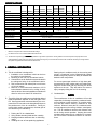
SPECIFICATIONS
59516.501
59516.506
59516.601
59516.606
600312.321 600312.421 600315.321
600315.421
13,500
MODEL NO.
57908.521 57912.621
57915.421 57915.521
57915.426 57915.526
57915.621
57915.626
59016.521
59016.526
59016.621
59016.626
Nominal Capacity (BTU/HR) *
7,100
13,500
13,500
15,000
15,000
11,000
11,000
13,500
11,000
Electrical Rating
13,500
115 VAC, 60 Hz., 1 ph.
Compressor Rated Load Amps
6.6
8.5
11.5
12.1
11.0
12.9
12.9
9.5
10.7
12.4
11.5
Fan Motor Rated Load Amps
2.5
2.5
2.5
2.5
2.5
2.5
2.5
3.1
3.1
3.1
3.1
Compressor Locked Rotor Amps
34.0
48.3
50.0
59.0
54.4
71.0
71.0
53.0
50.0
60.0
50.0
Fan Motor Locked Rotor Amps
5.8
5.8
5.8
5.8
5.8
6.0
6.0
8.8
8.8
8.8
8.8
Heater Amps/Watts @ 120VAC
NOT AVAILABLE ON THESE MODELS
12.7/1530
325 / 250
350/250
SCFM-High Speed Max./Min.
Total Static - Min/Max.
0.55 / 0.90" W.C.
Refrigerant R22 Charge ( Oz.)
17.0
16.0
13.5
Minimum Wire Size **
16.0
26.5
31.0
0.12/0.65" W.C.
16.5
16.0
15.5
101
96
17.0
12 AWG Copper Up to 24 ft.
20 Amp Time Delay Fuse or 20 Amp HACR Circuit Breaker
DC Circuit Protection
Installation must comply with all National, State, Providence, and/or local Electrical Codes
Installed Weight (Pounds)
Size ***
335/250
0.40/1.10
16.0
AC Circuit Protection
Minimum Generator
NOT AVAILABLE
75
1 Unit
2 Units
94
100
94
94
101
102
95
102
2.5 KW
3.5 KW
2.5 KW
3.5 KW
4.0 KW
5.0 KW
4.0 KW
5.0 KW
*
Maximum unit performance achieved at full rated voltage.
**
For distances over 24 ft. consult the National Electrical Code.
*** The Dometic Corporation gives GENERAL guidelines for generator requirements. These guidelines come from experiences people have had in
actual applications. When sizing the generator, the total power usage of your recreational vehicle must be considered. Also keep in mind generators
lose power at high altitudes and from lack of maintenance.
1. GENERAL INFORMATION
Starting the air conditioner early in the morning and
giving it a "head start" on the expected high outdoor
ambient will greatly improve its ability to maintain the
desired indoor temperature.
A. This air conditioner is designed for:
1. Installation on a recreational vehicle at the time
the vehicle is manufactured.
2. Mounting on the roof of a recreational vehicle.
3. Connection to an air distribution system located in
the ceiling/roof cavity of the recreational vehicle.
4. Roof construction with rafters/joists on minimum
of 16 inch centers.
5. Minimum of 2.00 inches and maximum of 5.50
inches distance between roof to ceiling of recreational vehicle. Alternate installation methods will
allow for roofs more than 5.50 inches thick.
For a more permanent solution to a high heat gain,
accessories like A&E outdoor patio and window awnings will reduce heat gain by removing the direct
exposure to the sun. They also add a nice area to
enjoy company during the cool of the evening.
C. Condensation
NOTE
B. The ability of the air conditioner to maintain the desired
inside temperature depends on the heat gain of the
RV. Some preventative measures taken by the occupants of the RV can reduce the heat gain and improve
the performance of the air conditioner. During extremely high outdoor temperatures, the heat gain of
the vehicle may be reduced by:
The manufacturer of this air conditioner will not be
responsible for damage caused by condensed moisture on ceilings or other surfaces. Air contains moisture and this moisture tends to condense on cold
surfaces. When air enters the RV, condensed moisture may appear on the ceiling, windows, metal parts,
etc. The air conditioner removes this moisture from
the air during normal operation. Keeping doors and
windows closed when this air conditioner is in operation will minimize condensed moisture on cold surfaces.
1. Parking the RV in a shaded area
2. Using window shades (blinds and/or curtains)
3. Keeping windows and doors shut or minimizing
usage
4. Avoiding the use of heat producing appliances
2