1
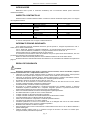
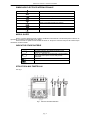
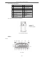
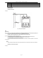
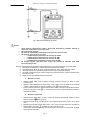
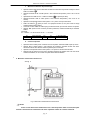
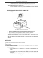
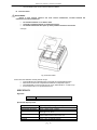
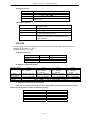
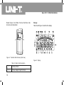
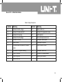
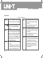
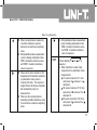
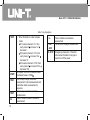
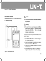
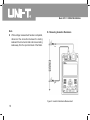
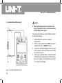
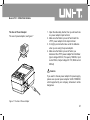
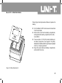
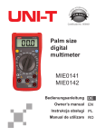
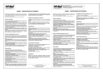
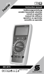
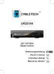
Manual de utilizare multimetru UT511
CUPRINS
INTRODUCERE ..................................................................................................................................... 2
INSPECTIA CONTINUTULUI.................................................................................................................. 2
INFORMATII PRIVIND SIGURANTA.................................................................................................... 2
SIMBOLURI ELECTRICE INTERNATIONALE...................................................................................... 3
MODUL SLEEP ...................................................................................................................................... 3
INDICATOR STARE BATERIE ............................................................................................................. 3
STRUCTURA MULTIMETRULUI ........................................................................................................... 3
AFISAJ ................................................................................................................................................... 4
FUNCTIILE TASTELOR......................................................................................................................... 5
MASURARE........................................................................................................................................... 6
A. Masurare tensiuni ............................................................................................................... 6
B. Masurare rezistenta de izolatie .......................................................................................... 6
a. Masurare continua ................................................................................................ 7
b. Masurare intrerupta .............................................................................................. 7
c. Masurarea indicelui de polarizare ........................................................................ 8
d. Functia comparare ................................................................................................ 8
C. Masurare rezistenta de valoare mica .................................................................................. 8
UTILIZAREA ADAPTORULUI PENTRU ALIMENTARE ...................................................................... 9
INTRETINERE ....................................................................................................................................... 9
A. Intretinere generala ........................................................................................................... 9
G. Inlocuire baterii . ................................................................................................................. 10
SPECIFICATII........................................................................................................................................ 10
Siguranta ................................................................................................................................ 10
Specificatii despre produs ....................................................................................................... 10
Specificatii generale ............................................................................................................... 11
Caracteristici generale ........................................................................................................... 11
PRECIZIE............................................................................................................................................... 11
A. Masurare tensiune ............................................................................................................... 11
B. Masurare rezistenta de izolatie ........................................................................................... 11
C. Masurarea rezistentelor de valoare mica ........................................................................... 11
pag. 1
Manual de utilizare multimetru UT511
INTRODUCERE
Multimetrul UT511 (numit in continuare multimetru) este un instrument dedicat pentru masurarea
rezistentei de izolatie.
INSPECTIA CONTINUTULUI
Desfaceti cutia si scoateti multimetrul afara. Controlati cu atentie urmatoarele repere pentru a va asigura
de integritatea acestora:
NUMAR
1
2
3
4
5
6
DESCRIERE
Manual de operare
Tester cu 1 fisa pentru o clema tip
crocodil
Tester cu 2 fise pentru o clema tip
crocodil
Baterii 1,5V (LR14 sau R14)
Cutie accesorii
Adaptor alimentare (optional contra
cost)
CANTITATE
1 buc.
1 buc
2 buc
8 buc.
1 buc.
1 buc.
In cazul in care lipseste ceva va rugam contactati furnizorul.
INFORMATII PRIVIND SIGURANTA
Acest multimetru respecta standardul IEC61010: grad de poluare 2, categorie supratensiune -CAT. II
1000V,CAT. III 600V si dubla izolare.
CAT. II: Nivel local, aparatura, echipament portabil etc., cu prag de tensiune mai mic decat CAT. III
CAT. III: Nivel de distributie, instalatii fixe, cu prag de tensiune mai mic decat CAT. IV
Folositi aparatul doar in conditiile specificate in acest manual.
In acest manual, atentionarile se refera la conditiile in care pot sa apara riscuri fata de utilizator, sau care
pot deteriora multimetrul sau echipamentul aflat in test.
Notele fac referire la informatii pertinente carora utilizatorul trebuie sa le acorde toata atentia.
Simbolurile electrice internationale folosite de multimetru si in acest Manual de Utilizare sunt explicate la
pagina 4.
REGULI DE SIGURANTA
ATENTIE
Respectati urmatoarele reguli pentru a preveni socurile electrice, ranirea accidentala, respectiv
defectarea multimetrului sau a echipamentului aflat in test:
•
Inspectati cu atentie carcasa aparatului inainte de utilizare. Nu folositi aparatul daca acesta prezinta
fisuri sau bucati de plastic lipsa. Asigurati-va ca exista o buna izolatie in zona conectorilor.
•
Inspectati, de asemenea, testerele pentru a verifica izolatia acestora. Verificati continuitatea acestora.
Inlocuiti testerele defecte doar cu altele identice cu aceleasi specificatii electrice.
•
Nu aplicati o tensiune mai mare de 1000 V DC sau 750 V AC.
•
Atunci cand se fac masuratori la o tensiune efectiva mai mare de 60V DC sau 42V rms AC, trebuie
acordata o atentie deosebita, existand riscul electrocutarii.
•
Folositi terminalele, functiile si scalele corespunzatoare.
•
Nu folositi si nu pastrati multimetrul in conditii de temperatura sau umiditate excesiva, in prezenta
materialelor explozive, inflamabile sau a campurilor magnetice puternice. In prezenta acestor factori
performantele multimetrului pot fi reduse sau acesta se poate deteriora.
•
Atunci cand folositi testerele, incercati sa tineti degetele in spatele aparatorilor.
•
Nu utilizati multimetrul cu parti din el sau carcasa desfacuta.
•
In timpul masurarii nu atingeti circuitul aflat in masurare.
•
In timpul masurarii rezistentei, deconectati alimentarea circuitului aflat in testare.
•
Conectati testerele ferm in multimetru inainte de masurare.
•
Pentru service folositi doar componente cu aceleasi specificatii electrice.
•
Circuitul intern al aparatului nu va putea fi modificat.
•
Curatarea aparatului se va face cu un material moale si un detergent slab. Nu se vor folosi materiale
abrazive sau solventi, pentru a preveni corodarea aparatului.
•
Multimetrul este indicat a se utiliza in incaperi.
•
Opriti multimetrul atunci cand nu este folosit si scoateti bateria atunci cand nu se va utiliza multimetrul o
perioda indelungata.
•
Verificati periodic bateria pentru a nu prezenta scurgeri si inlocuiti-o de indata ce acestea apar.
Scurgerea bateriei poate deteriora aparatul.
pag. 2
Manual de utilizare multimetru UT511
SIMBOLURI ELECTRICE INTERNATIONALE
Pericol de electrocutare.
Dubla izolatie.
AC (Curent alternativ).
DC (Curent continuu).
Impamantare.
Atentie. Consultati manualul de operare.
Baterie uzata.
Conform standardelor Uniunii Europene.
MODUL SLEEP
Pentru a mentine durata de viata a bateriei, multimetrul intra automat in modul Sleep daca in decurs de
aproximativ 15 minute nu este apasat nici un buton.
Pentru activare se apasa butonul POWER de doua ori. Timpul de 15 minute incepe sa fie masurat dupa
terminarea oricarei masurari.
INDICATOR STARE BATERIE
Indicator baterie
Tensiune baterie
8.5 V sau mai putin. Nu utilizati multimetrul cand
bateriile sunt descarcate.
8,6 V – 9 V. Bateriile sunt descarcate. Inlocuiti bateriile
cand acest simbol apare. Inca se mai pot face
masuratori.
9,1 V – 10,2 V
10,3 V sau mai mult
STRUCTURA MULTIMETRULUI
Vezi fig.1
Fig. 1 Structura frontala multimetru
pag. 3
Manual de utilizare multimetru UT511
Descriere partea frontala multimetru
1
2
3
Afisaj LCD
Buton derulare ◄
Buton lumina fundal afisaj
12
13
14
4
5
6
7
Buton stergere date
Buton derulare ▼
Buton pornire/oprire
Buton comparatie
15
16
17
18
8
9
Buton rezistenta de izolatie
Buton masurare tensiuni
19
20
10
Buton timer
21
11
Buton masurare rezistente
de valori mici
22
Buton test
Buton pentru pas
Buton retinere
(memorare) date
Buton reapelare date
Buton derulare ►
Buton derulare ▲
LINE: terminal intrare
rezistenta
COM: intrare tensiune
EARTH: terminal intrare
rezistenta
V: terminal intrare
tensiune
Testere
In fig. 2 se prezinta partea laterala a multimetrului
1 Obturator de
siguranta
2. Terminal adaptor
Fig. 2 Fata laterala multimetru
AFISAJ
vezi fig.3
Fig. 3 Afisaj
pag. 4
Manual de utilizare multimetru UT511
1
2
12
13
Reapelare date pornit
Indicator index polarizare
14
Simbol unitati
4
5
Indicator tensiune DC
Indicator date memorate
plin
Indicator prnteu stergere
date
Indicator tensiune AC
Indicator timer
15
16
6
7
8
Simbol pas
Indicator comparare
Indicator valori negative
17
18
19
9
10
11
Simbol timer1
Simbol timer2
Memorare date pornit
20
21
22
Buzzer continuitate pornit
Rezultat comparare OK
(GOOD)
Bara analogica
Risc de electrocutare
Rezultat comparare
negativ (NG)
Indicator pentru adaptor
Indicator baterie
3
FUNCTIILE TASTELOR
Tabelul de mai jos prezinta informatii cu privire la operatiile butoanelor.
ON/OFF
LIGHT
SAVE
LOAD
◄
►
▲
▼
STEP
COMP
TIME
Buton pornire multimetru. Tineti apasat pt. 1 sec. pentru a porni multimetrul
Pornire/oprire lumina fundal afisaj
Apasati pentru a memora datele masurate. Numarul maxim de date memorate este 18. Cand
numarul de memorari a ajuns la maxim, multimetru afiseaza FULL si nu mai memoreaza.
Apasati CLEAR pentru a sterge datele pentru a putea memora alte masurari
• Apasati odata pentru reapelare primele date salvate
• Apasati inca o data pentru a iesi din meniul LOAD
• Aceasta functie se poate utiliza numai cand nu exista tensiune mare la iesire
• In modul de lucru comparare rezistenta de izolatie, prin apasarea acetui buton se descreste
valoarea rezistentei de comparat
• Dupa masurarea indexului de polarizare, apasati TIME2 pentru afisarea valoarii rezistentei
si TIME1 pentru afisarea valorii rezistentei de izolatie
• Cand se seteaza durata timer pentru masurarea rezistentei, izolatiei sau index polarizare,
apasati acest buton pentru reducerea timpului. Durata maxima este de 30 minute si
multimetrul va intra singur in procesul de masurare.
• Cand se seteaza durata timer pentru masurarea rezistentei, izolatiei sau index polarizare,
apasati acest buton pentru cresterea timpului. Durata maxima este de 30 minute si
multimetrul va intra singur in procesul de masurare.
• In modul de lucru comparare rezistenta de izolatie, prin apasarea acetui buton se creste
valoarea rezistentei de comparat
• Dupa masurarea indexului de polarizare, apasati acest buton pentru afisarea indexului de
polarizare, TIME2 pentru afisarea valorii rezistentei si TIME1 pentru afisarea valorii
rezistentei de izolatie (secvential)
• In modul de masura rezistenta de izolatie, prin apasarea acestui buton se mareste domeniul
de tensiune
• In modul LOAD, prin apasarea acestui buton se reapeleaza valoarea anterioara memorata
• In modul de masura rezistenta de izolatie, prin apasarea acestui buton se micsoreaza
domeniul de tensiune
• In modul LOAD, prin apasarea acestui buton se reapeleaza valoarea urmatoare memorata
Apasati pentru afisarea secventiala S1-S2-S3:
• Daca multimetrul se afla in modul de masurare temporizata (timer):
o S1 semnifica increment de 1, fiecare apasare pe ► va creste cu 1, apasarea pe ◄ va
descreste cu 1
o S2 semnifica increment de 10, fiecare apasare pe ► va creste cu 10, apasarea pe ◄ va
descreste cu 10
o S3 semnifica increment de 30, fiecare apasare pe ► va creste cu 30, apasarea pe ◄ va
descreste cu 30
• Daca multimetrul se afla pe modul comparare:
o S1 semnifica increment de 1, fiecare apasare pe ► va creste cu 1, apasarea pe ◄ va
descreste cu 1
o S2 semnifica increment de 10, fiecare apasare pe ► va creste cu 10, apasarea pe ◄ va
descreste cu 10
o S3 semnifica increment de 30, fiecare apasare pe ► va creste cu 30, apasarea pe ◄ va
descreste cu 30
Se seteaza pragurile limita pentru test FAIL/PASS. Valoarea implicita este 100 MΩ.
Apasati acest buton pentru a trece in mod secvential pe modurile masurare continua, masurare
pag. 5
Manual de utilizare multimetru UT511
TEST
Ho
Lo
DCV/ACV
temporizata sau index polarizare
Apasati acest buton pentru a opri sau porni masurarea rezistentei de izolatie
Apasati acest buton pentru masurarea rezistentei de izolatie
Apasati acest buton pentru a masura rezistente de valori mici
Apasati acest buton pentru a masura tensiuni continue sau alternative
MASURARE
A. Masurare tensiuni
vezi fig.4
Fig. 4 Masurarea tensiunilor
Atentie
Pentru a se evita ranirea utilizatorului sau defectarea aparatului din cauza socurilor electrice, va
rugam nu incercati sa masurati tensiuni mai mari de 1000V DC sau 750 V AC.
Acordati o atentie deosebita atunci cand masurati tensiuni de valori mari.
Pentru a masura tensiuni, procedati astfel (vezi fig.4):
1. Apasati butonul DCV sau ACV pentru a selecta domeniul continuu (DC) sau alternativ (AC)
2. Conectati testerul rosu la terminalul V si testerul negru la terminalul COM
3. Conectati clestii tip crocodil la circuitul de masurat
4. Daca pe durata masurarii tensiunii continue pe testerul rosu apare o tensiune negativa, se va afisa pe
ecran semnul „-„.
NOTA
•
Dupa incheierea masurarii tensiunii, deconectati testerele de la circuitul aflat in testare si din multimetru.
B. Masurare rezistenta de izolatie
Vezi fig. 5
pag. 6
Manual de utilizare multimetru UT511
Fig. 5 Masurarea rezistentei de izolatie
Atentie
•
•
•
•
•
Cand masurati rezistenta de izolatie, deconectati alimentarea circuitului masurat si
descarcati condensatorii de tensiune mare
Nu scurtcircuitati testerele
Nu masurati rezistenta de izolatie dupa ce ati masurat o tensiune mare
Nu masurati mai mult de 10 sec cand:
o La 100V valoarea rezistentei este mai mica de 500kΩ
o La 250V valoarea rezistentei este mai mica de 1MΩ
o La 500V valoarea rezistentei este mai mica de 2MΩ
o La 1000V valoarea rezistentei este mai mica de 5MΩ
Nu atingeti testerele chiar daca sunt scoase din circuitul de masurare pana cand
tensiunile ajung la zero
Pentru a masura rezistenta de izolatie, setati multimetrul asa cum se arata in fig.5 si procedati astfel:
1. Apasati butonul HO pentru a selecta masurarea rezistentei de izolatie.
2. Apasati butoanele ▲ sau ▼ pentru a selecta tensiuni de 100V, 250V, 500V sau 1000V.
3. Conectati testerul rosu la terminalul LINE si testerul negru la terminalul EARTH.
4. Conectati crocodilii de culoare rosie si neagra la circuitul de masurat – tensiunea pozitiva este
la terminalul LINE.
5. Alegeti unul din urmatoarele moduri de masurare:
a.
•
Masurare continua
•
Apasati butonul TIME pentru a selecta modul de masurare continua, pe afisaj nu apare
iconita de timer
Apasati si tineti apasat butonul TEST pentru 1 sec. pentru a intra in domeniul de masurare
•
continua. Butonul TEST se aprinde si palpaie iconita
la fiecare 0.5 sec.
Dupa incheierea masurarii, apasati butonul TEST pentru a termina masuratoarea. Butonul
TEST se va stinge si iconita
rezistentei de izolatie.
b.
•
nu va mai palpai. Pe ecran va aparea valoarea masurata a
Masurare temporizata
Apasati butonul TIME pentru a intra in modul de masurare temporizata. Afisajul va arata
•
TIME1 si simbolul
apare pe ecran.
Apasati butoanele ◄ ► si STEP pentru a seta valoarea temporizarii ( intre 5 sec si 29:30
min).
Apasati si tineti apasat butonul TEST pentru 1 sec. pentru a incepe masurarea. Pe afisaj va
•
va palpai pe ecran la fiecare 0.5 sec.
aparea TIME1 si simbolul
Cand expira valoarea temporizarii, se termina procesul de masura in mod automat. Pe afisaj
apare valoarea masurata.
•
pag. 7
Manual de utilizare multimetru UT511
c.
•
•
•
•
•
•
Masurarea indexului de polarizare (PI)
Apasati butonul TIME pentru selectarea modului de masurare temporizata. Afisajul va arata
.
TIME1 si simbolul
Apasati butoanele ◄ ► si STEP pentru a seta valoarea temporizarii ( intre 5 sec si 29:30
min).
Apasati butonul TIME din nou. TIME2 si simbolul
va aparea pe afisaj.
Apasati butoanele ◄ ► si STEP pentru a seta valoarea temporizarii ( intre 5 sec si 30
minute).
Apasati si tineti apasat butonul TEST pentru 1 sec. pentru a incepe masurarea.
TIME1 si simbolul
apare pe ecran si va palpai la fiecare 0,5 sec pana cand se atinge
valoarea setata pentru TIME2.
• Cand cele 2 valori TIME1 si TIME2 ajung la valoarea setata, procesul de masura se opreste.
• Apasati ◄ ► pentru a trece succesiv prin index polarizare, valoarea rezistentei pe domeniul
TIME2 .
Informatii:
PI= 3 minute – 10 minute citire/ 30 sec. – 1 min citire
PI
Standard
d.
•
•
•
•
•
4 sau mai mult
Foarte bun
4-2
Bun
2-1
Avertizare
1 sau mai putin
Rau
Functia comparare
Apasati butonul COMP pentru a selecta modul comparare. Simbolul COMP apare pe ecran.
Apasati ◄ ► si STEP pentru a seta valoarea de comparat. Valoarea minima este 1MΩ.
Valoarea maxima este valoarea maxima permisa pentru masurare.
Apasati si tineti apasat butonul TEST pentru 1 sec pentru a efectua masuratoarea.
Simbolul NG va aparea pe ecran daca valoarea rezistentei de izolatie este mai mica decat
valoarea rezistentei, in caz contrar va aparea afisat simbolul GOOD.
C. Masurare rezistenta de valoare mica
Vezi fig. 6
Fig. 6 Masurarea rezistentelor de valoare mica
Atentie
Pentru a evita deteriorarea multimetrului sau a altor dispozitive aflate in testare,decuplati
circuitul si descarcati toti condensatorii de mare capacitate inainte de a masura rezistenta.
pag. 8
Manual de utilizare multimetru UT511
Pentru a masura rezistenta, setati aparatul ca in fig.6 si procedati astfel:
1. Apasati butonul LO pentru a selecta modul de masurare rezistenta de valoare mica.
2. Conectati testerul rosu la terminalul LINE si testerul negru la terminalul EARTH.
3. Conectati crocodilii de culoare rosie si neagra la circuitul pentru masurat. Cand valoarea
rezistentei este mai mica de 30 ohmi, buzzerul va suna.
4. Pe acest domeniu dse pot testa LED-uri. Conectand anodul diodei LED la testerul rosu, dioda
va lumina daca este buna. Daca dioda LED nu se aprinde, inseamna ca nu este buna.
UTILIZAREA ADAPTORULUI PENTRU ALIMENTARE
Vezi fig. 7
Fig. 7 Utilizarea adaptorului pentru alimentare
1.
2.
3.
4.
Deschideti orificiul de siguranta, pentru a avea acces la terminalul de alimentare.
Asigurati-va ca multimetrul este oprit apoi introduceti adaptorul in terminalul de alimentare.
Este recomandat sa scoateti toate bateriile din multimetru cand utilizati alimentatorul.
Asigurati-va ca multimetrul este oprit inainte de a scoate alimentatorul din el.
Caracteristici alimentator: tensiunea de intrare 230 VAC, frecventa 50/60 Hz, curent de intrare 50 mA,
tensiunea de iesire 15V DC, current de iesire max. 600 mA.
OBS. Utilizati alimentatorul SA48-150060EU recomandat de producator, in caz contrar puteti distruge
multimetrul.
INTRETINERE
Acest capitol ofera informatii de baza pentru intretinerea multimetrului.
AVERTISMENT
Nu incercati sa reparati multimetrul decat daca sunteti calificat pentru aceasta, si aveti aparatura
de calibrare si informatii de intretinere.
A.
Intretinere generala
•
•
•
•
Stergeti periodic carcasa cu un material umed si cu un detergent usor. Nu utilizati abrazivi sau
solventi.
Curatati terminalele cu o bucata de bumbac cu detergent, deoarece murdaria sau umiditatea
terminalelor poate afecta citirea valorilor.
Opriti multimetrul atunci cand nu-l folositi si scoateti bateriile cand nu-l folositi o perioada mai
lunga de timp.
Nu depozitati multimetrul in spatii cu umiditate ridicata, temperaturi ridicate, mediu exploziv,
materiale inflamabile sau camp magnetic puternic.
pag. 9
•
B.
Manual de utilizare multimetru UT511
Daca multimetrul este umed, uscati-l inainte de utilizare
Inlocuire baterii
AVERTISMENT
Pentru a evita socurile electrice sau chiar ranirea utilizatorului, scoateti testerele din
multimetru cand inlocuiti bateriile.
•
•
•
Nu amestecati baterii noi cu baterii uzate.
Verificati polaritatea bateriilor la instalarea acestora.
Nu utilizati multimetrul daca apare pe afisaj simbolul de baterie descarcata.
Vezi fig.8
Fig. 8 Inlocuire baterii
Pentru inlocuirea bateriilor urmariti pasii de mai jos:
•
Opriti multimetrul si indepartati toate conexiunile de la terminalele acestuia
•
Desurubati surubul de la compartimentul bateriilor si indepartati capacul
•
Inlocuiti bateriile cu unele noi (tip R14 sau LR14, baterii alcaline – in total 8 buc)
•
Puneti capacul din nou si puneti surubul la loc
SPECIFICATII
Siguranta
Certificari
Standarde
CE
IEC 61010 cat.II 1000V, cat. III 600V, dubla izolare
Specificatii despre produs
Afisaj LCD
Temperaturi functionare
Temperaturi de stocare
Umiditate relativa
Baterii
Dimensiuni
Greutate
Digital: afisaj max 9999, bara analogica
0oC - 40 oC (32 oF - 104 oF)
-20 oC - +60 oC (-4 oF - 140 oF)
≤85% @ 0 oC - 40 oC
o
o
≤90% @ -20 C - 60 C
8 buc 1,5V (R14 sau LR14) sau alimentator 15V.
Optional alimentatorul este contra cost.
202 x 155 x 94 mm
Aprox. 2 kg ( cu bateriile incluse)
pag. 10
Manual de utilizare multimetru UT511
Specificatii generale
Domeniu
Suprasarcina
Indicator baterie
Simboluri
Consum curent
Auto
Afisaj OL pe domeniul rezistenta de izolatie
Afisare
Pentru fiecare functie
Max.: 90mA
Mediu: 20mA
Caracteristici generale
Iluminare afisaj
Lumina intensa pentru citiri precise in zone cu
iluminare scazuta
Multimetrul alege in mod automat cel mai bun domeniu
Autoscalare
Atentionare
Masurare in mod COMP
Masurare PI
si o lumina rosie
Simbolul
Se utilizeaza acest mod pentru a compara diverse
nivele ale rezistentei de izolatie
Indicele de polarizare (PI) este o masura a rezistentei
de izolatie. Se pot preseta 2 domenii de temporizari
pentru masurare
PRECIZIE
Precizie: ±([%din valoarea masurata]+numarul celui mai putin semnificativ digit]), garanta timp de 1 an.
Temperatura de operare: 18 – 28 oC
Umiditate relative: 45 – 75 % RH
A. Masurare tensiune
Tensiune DC
±30 - ±1000V
Domeniu de masura
Precizie
Acuratete
Tensiune AC
30V – 750 V (50/60 Hz)
1V
±(2%+3)
B. Masurare rezistenta de izolatie
Tensiune iesire
Domeniu afisaj
100 V
0.1 MΩ – 99.9 MΩ
100 – 500 MΩ
Tensiune
in
circuit deschis
Curent testare
Scurt circuit
Precizie
DC100V + 20%, 0%
250 V
0.5 MΩ – 99.9 MΩ
100 – 999 MΩ
1 – 1.99 GΩ
DC250V + 20%, 0%
500 V
1 MΩ – 99.9 MΩ
100 – 999 MΩ
1 – 3.99 GΩ
DC500V + 20%, 0%
1mA-1.2mA@100kΩ
1000 V
2 MΩ – 99.9 MΩ
100 – 999 MΩ
1 – 10 GΩ
DC1000V + 20%,
0%
1mA-1.2mA@1MΩ
1mA-1.2mA@250kΩ
1mA-1.2mA@500kΩ
Aprox. 2mA
100kΩ – 100MΩ : +/- (3%+5) peste 100MΩ : +/- (5%+5)
C. Masurarea rezistentelor de valoare mica
OBS.: Pe orice domeniu de tensiune la iesire, daca valoarea rezistentei testate este mai mica de
5MΩ, timpul de masurare nu trebuie sa depaseasca 10 sec.
Functia
Domeniu de masura
Rezolutia
Precizie
Tensiune la iesire in circuit deschis
Buzzer
Protectie suprasarcina
pag. 11
Rezistenta
0.1Ω – 999.9Ω
0.1Ω
+/-(1%+3)
aprox. 2.8 V
Suna la valori mai mici de 30Ω
220V rms/10sec
Manual de utilizare multimetru UT511
ACEST MANUAL DE OPERARE SE POATE MODIFICA FARA INSTIINTARI PREALABILE.
Producator: UNI-TREND TECHNOLOGY(DONG GUAN)LIMITED
Adresa: Dong Fang Da Dao, Bei Shan Dong Fang Industrial
Development District, Hu Men Town, Dong Guan City,
Guang Dong Province, China
Sediu: Uni-Trend International Limited
Adresa: Rm901, 9/F, Nanyang Plaza 57 Hung To Road
Kwun Tong Kowloon, Hong Kong
Tel: (852) 2950 9168
Fax: (852) 2950 9303
Email: [email protected]
http://www.uni-trend.com
pag. 12
Model UT511
OPERATING MANUAL
Model UT511: OPERATING MANUAL
TITLE
Introduction
Unpacking the Meter
Safety Information
International Electrical Symbols
Battery Saver (Sleep Mode)
Battery Indication
The Meter Structure
Display
Key Functions
Measurement Operation
A.Measuring Voltages
B.Measuring Insulation Resistance
a) Continuous Measurement
b) Timed Measurement
c) Polarization Index (PI) Measurement
d) Compare Function
C. Low Resistance Measurement
PAGE
5
5
5
7
8
8
9
10
12
15
15
16
17
18
18
19
20
1
Model UT511: OPERATING MANUAL
TITLE
The Use of Power Adaptor
Maintenance
A. General Service
B. Replacing the Battery
Specifications
Safety and Compliances
Physical Specifications
General Specifications
Feature Summary
Detailed Accuracy Specifications
A. Voltage Measurement
B. Insulation Resistance Measurement
C. Low Resistance Measurement
2
PAGE
21
22
22
22
24
24
24
25
25
26
26
26
27
Model UT511: OPERATING MANUAL
Table
Title
1.
2.
3.
4.
5.
6.
7.
Unpacking Inspection
International Electrical Symbols
Battery Indication
Meter Front Description
Meter Side Description
Display Description
Key Description
Page
5
7
8
9
10
11
12
3
Model UT511: OPERATING MANUAL
4
Figure
Title
1.
2.
3.
4.
5.
6.
7.
8.
The Meter Front Structure
The Meter Side Structure
The Display
Voltage Measurement
Insulation Resistance Measurement
Low Resistance Measurement
The Use of Power Adaptor
Battery Replacement
Page
9
10
10
15
16
20
21
23
Model UT511: OPERATING MANUAL
Introduction
Uni-Trend Model UT511 insulation resistance tester
(hereafter, “the Meter”) is a handheld instrument
designed primarily to make resistance/ insulation
resistance measurement.
Unpacking the Meter
The Meter includes the following items:
Table 1. Unpacking Inspection
Item
1
2
3
Description
Qty
1 piece
English Operating Manual
One plug test lead to one alligator 2 pieces
1 piece
Two plugs test lead to one
alligator
4
1.5V Battery (R14 or LR14)
8 pieces
5
6
Tool Box
1 piece
1 piece
Power adaptor (optionally,
available at extra cost)
In the event you find any missing or damage, please
contact your dealer immediately.
Safety Information
This Meter complies with the standards IEC61010 safety
measurement requirement: in pollution degree 2,
overvoltage category (CAT. III 600V, CAT.II 1000V) and
double insulation.
CAT II: Local level, appliance, PORTABLE EQUIPMENT
etc., with smaller transient voltage overvoltages than
CAT. III
CAT III: Distribution level, fixed installation, with smaller
transient overvoltages than CAT. IV
Use the Meter only as specified in this operating manual,
otherwise the protection provided by the Meter may be
impaired.
Danger identifies conditions and actions that pose
hazard(s) to the user.
Warning identifies avoiding electric shock.
Caution identifies conditions and actions that may
damage the Meter and carrying out accurate
measurement.
5
Model UT511: OPERATING MANUAL
International electrical symbols used on the Meter and
in this Operating Manual are explained on page 4~5.
Danger
Use of instrument in a manual not specifed by
the manufactuer may impair safety features/
protection provided by the equipment. Read the
following safety information carefully before using
or servicing the instrument.
l Do not apply more than 1000VDC or 750V AC.
l Do not use the Meter around explosive gas,
vapor or dust.
l Do not use the Meter in a wet environment.
l When using the test leads, keep your figures
away from the lead contacts. Keep your
figures behind the finger guards on the leads.
l Do not use the Meter with any parts or cover
removed.
l When carrying out insulation measurement,
do not contact the circuit under test.
6
Warning
l Do not use the Meter if it is damaged or metal
part is exposed. Look for cracks or missing
plastic.
l Be careful when working above 30V rms, 42V
ac rms and 60V DC. Such voltages pose a
shock hazard.
l Discharge all loading of circuit under test after
measuring high voltage.
l Do not change battery when the Meter is in
wet environment.
l Place test leads in proper input terminals.
Make sure all the test leads are firmly
connected to the Meter’s input terminals.
Make sure the Meter is turned off when
opening the battery compartment.
Caution
l When performing resistance tests, remove all
power from the circuit to be measured and
discharge all the power.
Model UT511: OPERATING MANUAL
International Electrical Symbols
l When servicing the Meter, use only the same
model number or identical electrical
specifications of test leads and power adaptor.
l Do not use the Meter if the battery indicator
) shows a battery empty condition. Take
(
the battery out from the Meter if it is not used
for a long time.
l Do not use or store the Meter in an
environment of high temperature, humidity,
explosive, inflammable and strong magnetic
field. The performance of the Meter may
deteriorate after dampened.
l Soft cloth and mild detergent should be used
to clean the surface of the Meter when
servicing. No abrasive and solvent should be
used to prevent the surface of the Meter from
corrosion, damage and accident.
Dry the Meter before storing if it is wet.
International symbols on the Meter and in this manual
are explained in Table 2.
Table 2. International Electrical Symbols
Risk of electric shock
Equipment protected by double or
reinforced insulation.
DC Measurement
AC Measurement
Grounding
See Manual
Empty of Built-In Battery
Conforms to Standards of European Union
7
Model UT511: OPERATING MANUAL
Battery Saver (Sleep Mode)
Battery Indication
The Meter enters the Sleep Mode and blanks the display
if there is no button press for 15 minutes. This is done
to conserve battery power. The Meter comes out of
Sleep Mode when ON/OFF button is pressed two times.
There is a battery indicator shows on the display upper
left hand corner. Below Table 3 is the explanation:
Table 3. Battery Indication
Battery
The 15 minutes timer is disabled during any insulation
resistance measurement. The time period starts
immediately following any measurement.
Battery Voltage
Indicator
8.5V or less. It means the battery is
empty, don’t use the Meter as it cannot
guarantee accuracy.
8.6V~9.0V. It means the battery is nearly
empty, replacing battery is necessary.
Accuracy will not be affected.
9.1V~10.2V
10.3V or more
8
Model UT511: OPERATING MANUAL
The Meter Structure
Below Figure 1 and Table 4 shows the Meter front
structure and description
Table 4. Meter Front Description
1
2
3
4
5
6
7
8
9
10
LCD
Scroll Button
Emergency stop
Data Clear the
Display Backlight
Button,
Down Button
On/Off Button
Compare Button
Insulation Resistance
Button
Voltages
measurement Button
Timer Button.
Figure 1. The Meter Front Structure
11
Low Resistance
measurement Button
12
13
14
15
Test Button
Step Button
Data Store Button.
Data Recall Button
16
Scroll Button
17
Up Button
18 LINE: Resistance
input terminal
19 COM: Voltage input
terminal
20 EARTH: Resistance
input terminal
21 V: Voltage input
terminal
22 Testing leads
9
Model UT511: OPERATING MANUAL
Below Figure 2 and Table 5 shows the Meter side
structure and description
Display
Table 6 and Figure 3 describe the display.
Figure 2. The Meter Side Structure (Side View)
Figure 3. Display
Table 5. Meter Side Description
10
1
Safety Shutter
2
Power adaptor Input Terminal
Model UT511: OPERATING MANUAL
Table 6. Display Description
Number
Meaning
Number
Meaning
1
2
Indicator for DC voltage
Indicator for data store full
12
13
Data recall is on
Indicator for polarization index
3
Indicator for clearing
14
Unit symbols
4
5
Indicator for AC voltage
Indicator for timer
15
16
The continuity buzzer is on
Compare feature pass
6
Step symbol
17
Analogue bar graph
7
18
Risk of electric shock
8
Indicates selected pass/fail compare
value
Indicates for negative reading
19
Compare feature fail
9
10
Timer 1 symbol
Timer 2 symbol
20
21
Indicator for power adaptor
Battery life indicator
11
Data store is on
11
Model UT511: OPERATING MANUAL
Key Functions
Table 7. Key Description
ON/OFF
CLEAR/
SAVE
LOAD
12
Turn on or off the Meter. Press and hold
the button for 1 second to turn the Meter
on.
Press to clear the stored data,Push 1
SEC to turn on and off the display
backlight.
Press to store the current measurement
value. The maximum number of stored
reading is 18. When the stored readings
memory is full, the Meter shows FULL
and stop storing. Press CLEAR to clear
the stored value in order to store the
next measurement value.
l Press once to recall the first stored
value.
l Press again to exit Load feature.
l Load feature can only be used when
there is no high voltage output.
l Under insulation resistance measurement
mode: press to select one voltage
range up.
l Under load mode: press to recall
the previous stored value.
l Under insulation resistance measurement
mode: press to select one voltage
range down.
l Under load mode: press to recall
the next stored value.
l When set the timer duration for the
measurement of insulation resistance
or polarization index, press to
decrement the time. The maximum
length of time is 30 minutes, the
Meter will automatically carry out
measurement.
Model UT511: OPERATING MANUAL
Table 7. Key Description
l When compare feature measuring
insulation resistance, press to
decrement a resistance comparing
value.
l After polarization index measurement,
press to display polarization index,
TIME 2 insulation resistance value
and TIME 1 insulation resistance
value in sequence.
l When set the timer duration for the
measurement of insulation resistance
or polarization index, press to
increment the time. The maximum
length of time is 30 minutes, the Meter
will automatically carry out
measurement.
l When use the compare feature
measuring insulation resistance, press
to increment a resistance comparing
value.
l After polarization index measurement,
press to display polarization index,
TIME 2 insulation resistance value
and TIME 1 insulation resistance
value in sequence.
STEP
Press to display S1 S2
S3 in
sequence.
l When the Meter is under timed
measurement or polarization index
measurement:
S1 means increment of 1, then
each press of increase 1 or
decrease 1.
S2 means increment of 10, then
each press of increase 10 or
decrease 10.
S3 means increment of 30, then
each press of increase 30 or
decrease 30.
13
Model UT511: OPERATING MANUAL
Table 7. Key Description
STEP
COMP
TIME
TEST
Ho
14
When the Meter is under compare
mode:
S1 means increment of 1, then
each press of increase 1 or
decrease 1.
S2 means increment of 10, then
each press of increase 10 or
decrease 10.
S3 means increment of 100, then
each press of increase 100 or
decrease 100.
Set a pass / fail limit for insulation tests.
The default value is 100M
Pres to step through continuous
measurement, timed measurement and
polarization index measurement in
sequence.
Press to stop or start an insulation
resistance test
Press to initiate insulation resistance
measurement
l
Lo
DVC
/ACV
Press to initiate low resistance
measurement
Pres to initiate voltages measurement
E-STOP Emergency stop button. Press this
button when the Meter is hang and
cannot turn off the power.
Model UT511: OPERATING MANUAL
Measurement Operation
Below section explains how to make measurements.
A. Measuring Voltages
Caution
l
Special care should be taken when measuring
high voltage.
Warning
l To avoid harms to you or damages to the Meter,
please do not attempt to measure voltages
higher than 1000V DC or 750V AC, although
readings may be obtained.
Black
To measure voltages, set up the Meter as Figure 4 and
do the following:
Red
Figure 4. Voltages Measurement
1. Press DCV or ACV button to select DC voltage or
AC voltage measurement
2. Insert the red test lead into the V terminal and the
black test lead into the COM terminal.
3. Connect the red and black alligator clip to the circuit
to be measured.
4. During measurement, when the red test lead is
negative voltage, then “-“ shows on the display.
15
Model UT511: OPERATING MANUAL
Note
l When voltage measurement has been completed,
disconnect the connection between the testing
leads and the circuit under test and remove testing
leads away from the input terminals of the Meter.
B. Measuring Insulation Resistance
Red
Black
Figure 5. Insulation Resistance Measurement
16
Model UT511: OPERATING MANUAL
Caution
l When performing insulation resistance tests,
remove all power from the circuit to be measured
and discharge all the power.
l Do not short circuit two test leads under high
voltage status.
l Do not measure insulation resistance after high
voltage output.
l Do not measure over 10 seconds when:
100V measure resistance lower than 500k
250V measure resistance lower than 1M
500V measure resistance lower than 2M
1000V measure resistance lower than 5M
l When the measurement is completed, don’t
touch the circuit as the circuit has already stored
capacitance which may cause electric shock.
l Don’t touch the test leads even after it has been
removed from the circuit until voltages are all
released.
To measure insulation resistance, set up the Meter as
Figure 5 and do the following:
1. Press HO button to select insulation resistance
measurement.
2. Press and button to select voltages of 100V,
250V, 500V or 1000V.
3. Insert the red test lead into the LINE terminal and
the black test lead into EARTH terminal.
4. Connect the red and black alligator clip to the circuit
to be measured, positive voltage output from LINE
terminal.
5. Choose below insulation resistance measurement
mode.
l Press TIME button to select continuous
measurement mode, there is no timer icon on
the LCD.
l Press and hold TEST button for 1 second to
carry out continuous measurement. Output
insulation resistance testing voltage, TEST button
light up, blinks on every 0.5 seconds.
17
Model UT511: OPERATING MANUAL
Press TEST button to close the insulation resistance
measurement voltage when measurement is
, disappears.
completed. TEST button lights off
The LCD shows the current insulation resistance
measurement value.
l Press TIME button to select timed measurement
mode, the LCD displays TIME 1 and symbols.
l Press
, and STEP buttons to set the time
(00:05~29:30).
l Then press and hold TEST button for 1 second to
carry out timed measurement. TIME 1 and are
displayed and blinked on the LCD on every 0.5
seconds.
l When the set time is reached, the insulation
resistance measurement voltage will be closed and
the measurement will be automatically stopped.
The LCD displays the insulation resistance reading.
18
l Press TIME button to select timed measurement
mode, the LCD displays TIME 1 and symbols.
l Press
, and STEP buttons to set the time
(00:05~29:30).
l Press TIME button again. TIME 2, PI and symbols
appear on the LCD.
l Press
, and STEP buttons to set the time
(00:10~30:00).
l Then press and hold TEST button for 1 second to
carry out timed measurement.
l TIME 1 and are displayed and blinked on the
LCD on every 0.5 seconds before TIME 1 set time
is reached.
l TIME 2 and are displayed and blinked on the
LCD on every 0.5 seconds before TIME 2 set time
is reached.
l When the two set time are reached, the insulation
resistance measurement voltage will be closed and
the measurement will be automatically stopped.
The LCD displays the polarization index reading.
Model UT511: OPERATING MANUAL
l Press
, to set through the polarization index,
TIME 2 insulation resistance reading and TIME 2
insulation resistance reading.
Information:
PI = 3 minutes ~10 minutes reading / 30 second ~1
minutes reading
PI
4 or more 4~2
Standard The best Good
2.0~1.0
Warning
1.0 or less
Bad
l Press COMP button to select compare feature.
COMP symbol displays on the LCD.
, and STEP buttons to set the compare
l Press
value. The minimum value is 1M The maximum
value is the maximum tested voltage allowable
measurement value.
l Press and hold TEST button for 1 second to carry
out the measurement.
l The NG symbol will display if the insulation resistance
value is smaller than resistance value. Otherwise
GOOD symbol will be displayed.
19
Model UT511: OPERATING MANUAL
C. Low Resistance Measurement
Caution
l When performing insulation resistance tests,
remove all power from the circuit to be measured
and discharge all the power.
Red
To measure low resistance, set up the Meter as Figure
6 and do the following:
Black
Figure 6. Low Resistance Measurement
20
1. Press LO button to select low resistance
measurement..
2. Insert the red test lead into the LINE terminal and
the black test lead into EARTH terminal.
3. Connect the red and black alligator clip to the circuit
to be measured. When the resistance is less than
30 the buzzer sounds.
4. This range can test LED diode. Connect the anode
LED diode to the red test lead, the LED diode will
light up if it is good. If the LED diode does not light
up, it means it is damaged.
Model UT511: OPERATING MANUAL
The Use of Power Adaptor
The use of power adaptor, see figure 7
1. Open the side safey shutter, then you will see there
is a power adaptor input terminal.
2. Make sure the Meter is power off and Insert the
UT511 power adaptor to the input terminal.
3. It is highly recommed to take out all the batteries
when you are using the power adaptor.
4. Make sure the Meter is power off when you
disconnect the UT511 power adaptor from the Meter.
(Input voltage 230VAC, Frequency 50/60Hz, Input
current 50mA, Output voltage DC 15V, MAX current
600mA)
Caution
If you want to choose power adaptor for power supply,
please use special power adaptor SA48-150060EU
which supported by our company, otherwise it will be
dangerous.
Figure 7. The Use of Power Adaptor
21
Model UT511: OPERATING MANUAL
Maintenance
This section provides basic maintenance information
including battery replacement instruction.
Warning
Do not attempt to repair or service your Meter unless
you are qualified to do so and have the relevant
calibration, performance test, and service
information.
A. General Service
l Periodically wipe the case with a damp cloth and
mild detergent. Do not use abrasives or solvents.
l To clean the terminals with cotton bar with detergent,
as dirt or moisture in the terminals can affect readings.
l Turn the Meter to OFF when it is not in use.
l Take out the battery when it is not using for a long
time.
l Do not use or store the Meter in a place of humidity,
high temperature, explosive, inflammable and strong
magnetic field.
l If the Meter is wet, dry it before use.
22
B. Replacing the Battery
Warning
To avoid electric shock, remove all the test leads
from the Meter when replacing the batteries.
Caution
l Don’t mix to use old and new batteries.
l Be careful the polarity is correct when installing
batteries.
l Do not use the Meter if the battery indicator
(
) shows a battery empty condition.
Model UT511: OPERATING MANUAL
Follow Figure 8 and proceed as follows to replace the
battery:
l Turn the Meter to OFF and remove all connections
from the terminals.
l Remove the screw from the battery compartment,
and separate the battery compartment from the
case bottom.
l There are 8pcs of 1.5V (R14) carbon battteries in
the meter, except this, it can support 1.5V (LR14)
alkalescence batteries and the special power apapter
which our company provided.
l Rejoin the case bottom and battery compartment,
and reinstall the screw.
Figure 8. Battery Replacement
23
Model UT511: OPERATING MANUAL
Specifications
Safety and Compliances
Certification
Compliances
IEC 61010 CAT.II 1000V, CAT.III 600V overvoltage and double insulation standard
Physical Specifications
Display (LCD)
Operating Temperature
Storage Temperature
Relative Humidity
Battery Type
Dimensions (HxW xL)
Weight
24
Digital: 9999 counts
Analog bar graph.
-10 ~40 (14 ~104 )
-20 ~60 (-4 ~140 )
85% @ -10 ~40 below;
90% @ -20 ~60 :
8pcs of 1.5V (R14 or LR14) batteries or DC15V power adaptor. DC15V
power adaptor is optionally at extra cost.
202 x 155 x 94 mm
Approx. 2kg (including battery)
Model UT511: OPERATING MANUAL
General Specifications
Range
Overloading
Battery Indicator
Icon Display
Current Consumption
Auto
Display OL on insulation resistance range
Display
Equips with function and battery indicator icons.
Maximum: around 90mA
Average: around 20mA
Feature Summary
Display Backlight
Autorange
Warning
Voltage
COMP Measurement
PI Measurement
Bright backlight for clear readings in poorly lighted areas.
The Meter automatically selects best range
and red light will on.
Auto release voltage
Use the Compare function to set a pass/fail compare level for the insulation
measurements.
Polarization Index is the ratio of insulation resistance. You can pre-set two
point of times and automatically carry out the measurement.
25
Model UT511: OPERATING MANUAL
Detailed Accuracy Specifications
Accuracy: ([% of reading] + [number of least significant digits), guarantee for 1 year.
Operating temperature: 18 ~28
Relative humidity: 45~75%RH
A. Voltage Measurement
Measurement Range
Resolution
Accuracy
DC Voltage
30 ~ 1000V
1V
(2%+3)
AC Voltage
30V~750V (50/60Hz)
30~100V (2%+5)
100~750V (2%+3)
B. Insulation Resistance Measurement
Output Voltage
Display Range
100V
0.1M ~99.9M
100~500M
Open Circuit Voltage DC100V + 20%,-0%
Test Current
1mA~1.2mA@100k
Short Circuit
Accuracy
100k
26
250V
0.5M ~99.9M
100~999M
1.00~1.99G
DC250V + 20%, -0%
1mA~1.2mA@250k
to 100M
500V
1M ~99.9M
100~999M
1.00~3.99G
DC 500V + 20%, -0%
1mA~1.2mA@500k
Around 2.0mA
: (3%+5) 100M
above: (5%+5)
1000V
2M ~99.9M
100~999M
1.00~10.00G
DC1000V + 20%, -0%
1mA~1.2mA@1M
Model UT511: OPERATING MANUAL
Caution
At any output voltage, when the tested resistance is les than 5MΩ, the testing time cannot exceed 10 seconds.
C. Low Resistance Measurement
Function
Measurement Range
Resolution
Accuracy
Maximum open circuit voltage
Buzzer
Overload Protection
Resistance
0.1Ω~999.9Ω
0.1Ω
(1%+3)
Around 2.8V
Open at less than 30Ω
220V rms/10 seconds
27
Model UT511: OPERATING MANUAL
*END*
This operating manual is subject to change without notice.
28
Model UT511: OPERATING MANUAL
Copyright 2006 Uni-Trend Group Limited.
All rights reserved.
Manufacturer:
Uni-Trend Technology (Dongguan) Limited
Dong Fang Da Dao
Bei Shan Dong Fang Industrial Development District
Hu Men Town, Dongguan City
Guang Dong Province
China
Postal Code: 523 925
Headquarters:
Uni-Trend Group Limited
Rm901, 9/F, Nanyang Plaza
57 Hung To Road
Kwun Tong
Kowloon, Hong Kong
Tel: (852) 2950 9168
Fax: (852) 2950 9303
Email: [email protected]
http://www.uni-trend.com
29