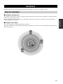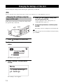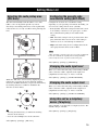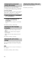
1
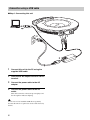
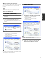
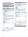
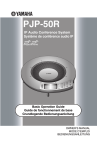
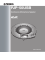
PJP-50USB
Conference Microphone Speaker
VOL
3
CLEAR
1
4
7
2
5
6
MIC MUTE
9
8
0
STANDBY
ENTER
MENU
User’s Manual
Contents
INTRODUCTION
INTRODUCTION
Introduction ................................................................................2
Controls and Functions..............................................................3
Top panel..................................................................................3
Side panel .................................................................................4
Bottom panel ............................................................................4
Top screen ................................................................................4
PREPARATION
PREPARATION
Connection ..................................................................................5
Check the following before connecting this unit to the PC......5
Connection using a USB cable.................................................6
Connection using audio connection cables ..............................9
Installation ................................................................................13
Notes for installation ..............................................................13
CONFIGURATION
CONFIGURATION
Changing the Settings of This Unit.........................................14
Changing the settings using the keys on this unit ..................14
Setting Menu List .....................................................................15
Selecting the audio pickup area (Mic Area)...........................15
Configuring the acoustic echo cancellation setting
(AEC Effect)...........................................................................15
ADDITIONAL
INFORMATION
Changing the audio input level...............................................15
Changing the audio output level.............................................15
Using this unit as a telephony device (Telephony) ................15
Configuring the environment setting (Environment) .............16
Selecting the menu language (Language) ..............................16
Restoring this unit to factory settings.....................................16
Checking the settings of this unit ...........................................16
ADDITIONAL INFORMATION
Troubleshooting........................................................................17
Q1: LED indicator does not light up ......................................17
Q2: Have an audio problem....................................................17
Using the Latest Features ........................................................18
Specifications ............................................................................19
General ...................................................................................19
Audio ......................................................................................19
1
Introduction
Thank you for purchasing Yamaha PJP-50USB. This product is a microphone/speaker unit to be connected to a video or
web conference system for use as its audio terminal. Before operating this unit, please read this manual carefully.
VOL
3
2
1
5
CLEAR
4
8
7
6
MIC MUTE
9
#
0
STANDBY
ENTER
MENU
PJP-50USB (2 persons)
Headset
Web
conference
VOL
3
2
1
5
CLEAR
4
8
7
6
MIC MUTE
9
#
0
STANDBY
ENTER
MENU
PJP-100UH (6 persons)
PJP-50USB (3 persons)
■Connection to a video or web conference system
This unit can be connected to a video or web conference system for use as a microphone/speaker of the system.
Replacing the audio input/output of the system with this unit achieves a smoother conference for both talkers and
listeners.
■Audio conference that is "easy to talk" and "easy to hear"
This unit employs arrayed microphones with high voice capturing capability and speakers with high voice reproduction
capability. It also incorporates a high-performance adaptive echo canceller to eliminate interruptions of sound or drop in
the voice level when multiple talkers speak simultaneously. These features make your audio conference "easy to talk" and
"easy to hear".
2
Controls and Functions
INTRODUCTION
Top panel
1
2
VOL
3
2
1
5
CLEAR
4
8
7
6
MIC MUTE
9
#
0
STANDBY
ENTER
MENU
3 4
5 6 78
1 Microphone indicators
When this unit is turned on, the LEDs light in blue. The
LEDs are turned off while the microphones are being
muted.
9
0
A
7 /
Press either key to select a setting item or move the cursor
up or down.
8 ENTER/MENU
2 Arrayed microphones
• Press the key to enter a setting.
The eight microphones on the top panel pick up the voices
of the talkers.
• Press the key to display the setting menu.
9 Numeric keys
3
Reserved for future extension.
0 MIC MUTE
4
/ STANDBY
• While the setting item is being displayed, press the key
to return to the top screen.
• Hold down the key to set the system to the standby
mode.
y
Hold
Press the key to select a setting item.
Press the key to temporarily defeat (mute) the
microphones of this unit. The key lights in orange when
muted.
Pressing the key when the microphones are muted releases
the mute and turns the LED off.
A VOL +/–
/
STANDBY to exit the standby mode.
Press either key to adjust the speaker volume. Holding
either key increases or decreases the volume continuously.
5 Display
The LCD shows the current status of this unit.
6 CLEAR
Press the key to cancel a setting without saving it or to
return to the previous screen.
3
Side panel
1 2
DC IN 12V
3 4
IN AUDIO OUT
1 USB port
3 AUDIO IN terminal
Connect to the PC using a USB cable.
Connect to the line output terminal or the headphone
output terminal of an audio equipment or PC.
2 DC IN 12V terminal
4 AUDIO OUT terminal
Connect the provided AC adapter.
Connect to the line input terminal or the microphone input
terminal of an audio equipment or PC.
Bottom panel
1 Serial label
2
The label carries the following information.
• MODEL No.: Model number of this unit.
• SER.: Serial number for use in management/distinction
of this unit.
2 Arrayed speakers
The four arrayed speakers on the bottom panel for use in
output of the audio.
3 Adjuster
If you cannot place this unit stably because of the shape of
the desk or other reasons, adjust the foot height using the
adjuster.
1
2 3
Top screen
1 USB mode
Displays the setting of the USB mode.
AUD : This unit functions in the audio mode.
TEL : This unit functions in the telephony mode.
Volume
2 MIC
Displays the audio input level of the microphones.
3 Volume
Displays the audio output level of the speakers.
1
2
345
4 USB indicator
Lights up when this unit is connected to the PC using a
USB cable.
5 Speaker mute
Lights up when the speakers are muted.
4
Connection
Check the following before
connecting this unit to the PC
■System requirement
Prepare the supplied USB cable.
• USB port: USB 1.1 or later (USB 2.0 recommended)
Note
Notes
Be sure to use the supplied USB cable. Otherwise operation
failure may be caused.
• You can not connect more than one conference
microphone speaker to the PC at the same time.
■Audio connection cable (when connecting
to a PC or external device without using a
USB cable)
Prepare two audio connection cables (stereo mini-jack
cables).
• Connect this unit and the PC directly. Connecting them
through a USB hub may cause problems in operation.
• Audio reproduction may be interrupted depending on
the PC usage situations (workloads or available memory
space).
y
The designs of the audio input/output terminals of video
conference systems vary depending on the models.
Always use audio connection cables having the plugs
matching the audio input/output terminals of the
connected video conference system. Note that the plugs
connected to the Projectphone should always be the stereo
mini plugs.
5
PREPARATION
■USB cable (when connecting to a PC
using a USB cable)
The PC connected to this unit should meet the following
system requirement.
• OS: Windows 7, Windows Vista SP1 or later (32 bit),
Windows XP SP2 or later (32 bit), Windows 2000
Professional SP4
Connection using a USB cable
■Step 1: Connecting this unit
To USB port
4
1
3
1 Connect this unit to the PC using the
supplied USB cable.
2 Connect the AC adapter to the DC IN 12V
terminal.
3 Connect the power cable to the AC
adapter.
4 Connect the power cable to the AC
outlet.
This unit is turned on. The start-up sound plays and
the microphone indicators light up.
y
You do not need to install the USB driver separately
because this unit is recognized as a basic audio device by
the PC.
6
2
■Step 2: Checking the connection
After connecting this unit to the PC, follow the procedure
below to check whether the PC recognizes this unit
properly.
6 Click the "Voice" tab.
Click
Note
The items in the setting screen vary depending on the PC.
When using Windows XP
1 Click [Start] - [Control Panel].
Devices".
3 Click "Sounds and Audio Devices".
7 Configure the settings as shown below.
• "Default device" in "Voice playback":
Yamaha PJP-50USB
• "Default device" in "Voice recording":
Yamaha PJP-50USB
The "Sounds and Audio Devices Properties" screen
appears.
4 Click the "Audio" tab.
Click
Change
5 Configure the settings as shown below.
• "Default device" in "Sound playback":
Yamaha PJP-50USB
• "Default device" in "Sound recording":
Yamaha PJP-50USB
Change
y
Normally, "Yamaha PJP-50USB" is automatically selected
when this unit is connected to the PC.
8 Click "OK" to close the "Sounds and
Audio Devices Properties" screen.
Change
Change
y
Normally, "Yamaha PJP-50USB" is automatically selected
when this unit is connected to the PC.
7
PREPARATION
2 Click "Sounds, Speech, and Audio
When using Windows 7/Windows Vista
In this section, Windows Vista is used as an example.
6 Click the "Recording" tab.
1 Click [Start] - [Control Panel].
2 Click "Classic View".
Click
3 Double-click "Sound".
The "Sound" screen appears.
4 Click the "Playback" tab.
7 Configure the setting as shown below.
Select "Yamaha PJP-50USB" in "Microphone", and
then click "Set Default".
Click
5 Configure the setting as shown below.
Select "Yamaha PJP-50USB" in "Speakers", and then
click "Set Default".
Click
y
Normally, "Yamaha PJP-50USB" is automatically selected
when this unit is connected to the PC.
8 Click "OK" to close the "Sound" screen.
Click
y
Normally, "Yamaha PJP-50USB" is automatically selected
when this unit is connected to the PC.
8
Connection using audio connection cables
■Step 1: Connecting this unit
5
3
2
1
PREPARATION
To audio input
terminal
To audio output
terminal
4
1 Connect the AUDIO IN terminal of this
unit to the audio output terminal of the
PC or video conference system.
2 Connect the AUDIO OUT terminal of this
unit to the audio input terminal of the PC
or video conference system.
3 Connect the AC adapter to the DC IN 12V
terminal.
4 Connect the power cable to the AC
adapter.
5 Connect the power cable to the AC
y
• The audio may be distorted or too low in certain
operating environments. In such a case, adjust "AUDIO
IN LEVEL" and "AUDIO OUT LEVEL" in "Settings".
For details, see page 15.
• To use this function, you need to change the settings of
the audio input/output of the PC and video conference
system. For the settings of the PC, see "Changing the
settings of the PC" (page 10).
• The designs of the line input/output terminals of video
conference systems vary depending on the models.
Always use audio connection cables having the plugs
matching the line input/output terminals of the
connected video conference system. The plugs
connected to the Projectphone should always be the
stereo mini plugs regardless of the designs of the plugs
connected to the video conference system.
outlet.
This unit is turned on. The start-up sound plays and
the microphone indicators light up.
9
■Step 2: Changing the settings of the PC
When you connect this unit to a PC for use as a
microphone/speaker of a conference system, you need to
change the setting so that the audio input from this unit to
the PC is not output to this unit. It is also necessary to
change the setting so that the audio input from the
connected terminal is accepted.
6 In the "Mic Volume" field, select the
"Mute" checkbox.
Note
The items in the setting screen vary depending on the PC. When
they are different from the following description, refer to the
instruction manuals of your PC or the sound card installed to your
PC, and set the parameters as follows.
Select
When using Windows XP
1 Click [Start] - [Control Panel].
Note
Which item to mute depends on the connection method.
Configure the settings depending on your operating environment.
2 Click "Sounds, Speech, and Audio
7
Devices".
In the "Sound recording" field, click
"Volume".
3 Click "Sounds and Audio Devices".
The "Sounds and Audio Devices Properties" screen
appears.
4 Click the "Audio" tab.
Click
Click
5 In the "Sound playback" field, click
"Volume".
Click
10
When using Windows 7/Windows Vista
8 In the "Mic Volume" field, clear the
In this section, Windows Vista is used as an example.
"Mute" checkbox.
1 Click [Start] - [Control Panel].
2 Click "Classic View".
3 Double-click "Sound".
The "Sound" screen appears.
PREPARATION
4 Click the "Playback" tab.
Click
Clear
Notes
• Which item to mute depends on the connection method.
Configure the settings depending on your operating
environment.
• The name of the checkbox may be "Select" on some PCs. In
such a case, select the "Select" checkbox in the appropriate field
depending on the connection method.
5 Select "Speakers" depending on the
connection method, and then click
"Properties".
The "Speakers Properties" screen appears.
Click
Note
The items displayed in the screen vary depending on the
connection method and PC. Configure the PC depending on your
operating environment.
11
6 Click the "Levels" tab.
9 Select "Microphone" depending on the
connection method, and then click
"Properties".
The "Microphone Properties" screen appears.
Click
7 In the "Microphone" field, click
to set
the mute function.
Click
Click
8 Click the "Recording" tab.
10 Click the "Levels" tab.
Click
Click
11 In the "Microphone" field, click
to
cancel the mute function.
Click
Note
The items displayed in the screen vary depending on the
connection method and PC. Configure the PC depending on your
operating environment.
12
Installation
Read the following notes and install this unit where you actually use it, such as a conference room.
Notes for installation
■Installation environment
■Position of the talkers
This unit can pick up the audio from 360-degree direction.
The audio pickup area varies depending on the talkers and settings. For details, refer to "Selecting the audio pickup area
(Mic Area)" (page 15).
VOL
3
2
1
5
CLEAR
4
8
7
6
MIC MUTE
9
#
0
STANDBY
ENTER
MENU
13
PREPARATION
The speakers of this unit are arrayed on the bottom panel facing down. Place this unit horizontally on a desktop without
placing any object below this unit.
If you cannot place this unit stably because of the shape of the desk or other reasons, adjust the foot height using the
adjuster equipped on the bottom.
Changing the Settings of This Unit
You can change the settings of this unit using the operation keys on this unit
Note
For the composition of the setting menus and the content of each setting item, see "Setting Menu List" (page 15).
Changing the settings using the
keys on this unit
Follow the procedure below to change the settings using
the operation keys on this unit.
4 Press
or to select a setting item,
and then press ENTER.
For the composition of the setting menus, see
"Setting Menu List" (page 15).
5 Change the parameter, and then press
/
CLEAR
VOL
3
2
1
5
CLEAR
4
8
7
The setting you have configured is saved in this unit.
6
MIC MUTE
9
#
0
STANDBY
ENTER
MENU
ENTER/MENU
1 Press
to display the top screen.
2 When the top screen appears, press
MENU.
Volume
MIC
The "Menu" screen appears.
3 Select "Settings", and then press
ENTER.
Menu
1. View Settings
2. Settings
The "Settings" screen appears.
14
ENTER.
y
To return to the previous screen without saving the setting,
press CLEAR.
Setting Menu List
Selecting the audio pickup area
(Mic Area)
This unit automatically tracks the talker's voice. The
talker's voice can be picked up with very narrow
directivity so that background noise can be significantly
reduced. The voice of only one talker can be picked up at a
time.
Today...
Configuring the acoustic echo
cancellation setting (AEC Effect)
Configure the acoustic echo cancellation setting
depending on your operating environment. Normally, you
do not need to change it from "Low" (default).
• Low (default): Select this setting when this unit is used
in an ordinary conference room, open space, or office.
The communication quality is most stable in this
setting.
• Mid: Select this setting if echo is produced at the other
party when this unit is used in "Low". This setting is
suited for use in a room with high reverberations.
5
4
8
7
6
MIC MUTE
9
#
0
ENTER
MENU
Note
Tracking the talker's
direction automatically
"Mid" and "High" can improve the echo processing capability but
lowers the communication quality. These settings should be
selected only when echo is produced at the other party.
Select [Menu] - [Settings] - [AEC Effect].
Changing the audio input level
VOL
3
2
1
5
CLEAR
4
8
7
6
MIC MUTE
9
#
When you connect this unit using commercially available
audio connection cables, adjust the audio input level
(amplification) in the range of -12.0 to +12.0 dB.
0
STANDBY
ENTER
MENU
Next...
Select [Menu] - [Settings] - [AUDIO IN LEVEL].
While the "Mic Area" screen is being displayed, press a
numeric key to specify the area in which the tracking
function is disabled. Each time you press the numeric key,
the tracking function is enabled or disabled in the
direction as shown below.
2
1
3
4
6
VOL
5
4
8
7
6
MIC MUTE
9
#
0
ENTER
MENU
7
When you connect this unit using commercially available
audio connection cables, adjust the audio output level
(amplification) in the range of -12.0 to +12.0 dB.
Select [Menu] - [Settings] - [AUDIO OUT LEVEL].
3
2
1
CLEAR
STANDBY
Changing the audio output level
9
8
y
• Pressing the numeric key (5) enables the tracking
function in the all areas.
• You can select multiple areas at the same time.
Using this unit as a telephony
device (Telephony)
Select "Enable" to use this unit as a telephony device. The
default setting is "Disable".
Select [Menu] - [Settings] - [Telephony].
Select [Menu] - [Settings] - [Mic Area].
15
CONFIGURATION
• High: Select this setting if echo is still produced at the
other party when this unit is used in "Mid".
VOL
3
2
1
CLEAR
STANDBY
Configuring the environment
setting (Environment)
Utilize this function to use this unit in multiple
environments. Selecting "Environment 1", "Environment
2" or "Environment 3" switches the settings of this unit.
To save the settings
Before using this function, you need to save the settings to
"Environment 1", "Environment 2" or "Environment 3".
Follow the procedure below to save the settings.
1 Select "Environment 1", "Environment
2" or "Environment 3".
2 Configure the settings of this unit
according to your operating
environment.
The settings you have configured are automatically
saved.
Select [Menu] - [Settings] - [Environment].
Selecting the menu language
(Language)
• Japanese: Select this setting to display the menus in
Japanese.
• English (default): Select this setting to display the
menus in English.
• Chinese: Select this setting to display the menus in
Chinese.
Select [Menu] - [Settings] - [Language].
Restoring this unit to factory
settings
You can restore this unit to the factory settings. Select
"Yes" to reset all settings. To cancel the reset operation,
select "No".
Note
Restoring this unit to the factory settings clears all settings you
have configured.
Select [Menu] - [Settings] - [Restore Settings].
16
Checking the settings of this unit
Display the current setting information.
Select [Menu] - [View Settings].
Troubleshooting
Refer to the following tables when this unit does not function properly. If the problem you are experiencing is not listed
or the instruction does not solve, please contact the retailer or dealer who you purchased the product from.
Q1: LED indicator does not light up
Problem
The power is not turned on.
Cause
Remedy
The power cable is disconnected or connected
improperly.
Connect the power cable to the AC outlet and AC
adapter firmly.
The AC adapter is disconnected or connected
improperly.
Connect the AC adapter firmly.
This unit is set in the standby mode.
Exit the standby mode. For information on how
to exit it, see page 3.
Q2: Have an audio problem
Problem
Cause
Remedy
The microphones are muted on the other unit.
–
The speaker mute function is working.
Cancel the speaker mute function.
The audio is interrupted.
The audio connection cable is disconnected or
connected improperly.
Connect the audio connection cable firmly.
The speaker volume can not be
turned up when this unit is
connected using audio
connection cables.
The volume setting in Windows is too low.
Adjust the volume setting in Windows.
The unit generates feedback
noises.
This unit is placed near the wall.
Move this unit away from the wall.
An object is placed near this unit.
Avoid placing an object in front of the
microphones of this unit.
This unit is used in a room with high
reverberation.
• Place objects with high sound absorbance in
the room other than in front of the
microphones.
• Decrease the speaker volume to reduce
reverberations.
17
ADDITIONAL
INFORMATION
The audio from the other unit
cannot be heard.
Using the Latest Features
You can download the firmware (program to control the functions of this unit) to use the latest features. For details, refer
to "PJP-50USB Writer Instruction Manual" included in the supplied CD-ROM.
18
Specifications
General
Audio
Interface:
Microphones:
USB 2.0 (full), Analog I/O (stereo-mini),
AC adapter (DC 12V IN)
8 units
Speakers:
Power consumption (max):
4 units
Approx. 9.0 W
Frequency bandwidth:
Radio interference standard:
FCC Part 15 (US)
EN55022 (EU)
For recording: 200 to 20,000 Hz
For playback: 300 to 20,000 Hz
Signal processing:
Operating environment:
Temperature: 0 to 40°C (32 to 104°F),
Humidity: 20 to 85%
Adaptive echo canceller, Noise reduction, Microphone
array control
Dimensions (W x H x D):
283.4 x 51.5 x 297.5 mm (11-3/16" x 2-9/32" x 11-23/32")
ADDITIONAL
INFORMATION
Weight (excl. AC adapter):
1.4 kg (3.09 lbs)
Power source:
100 to 240 V AC (50/60 Hz)
Accessories:
USB cable (2.0 m), AC adapter (1.8 m),
Power cable (2.0 m), CD-ROM, Quick Start Guide
PC environment:
OS: Microsoft® Windows® 7/Vista/XP/2000
USB port: USB 1.1 or later (USB 2.0 recommended)
Other:
Firmware revision upgrade
(transfer from PC through USB)
19
November 2010, 3rd edition