1
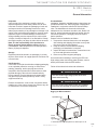
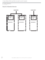
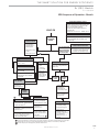
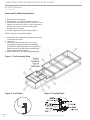
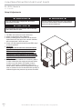
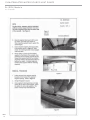
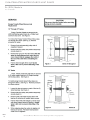
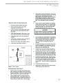
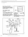
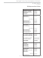
Rx (ERV) Series
Table of Contents
Commercial Rooftop
Energy Recovery Ventilator
Model Nomenclature
3-4
General Information
5
Sequence of Operation Overview
6
ERV Sequence of Operation - Sheet A
7
ERV Sequence of Operation - Sheet B
8
ERV Sequence of Operation - Sheet C
9
Roofcurbs for Mated Applications
10
Installing Hoods to ERV Unit
11
Setup & Adjustments
12
ERV Start-Up
13
Maintenance
13
AirXchange Wheel Service
15
ERV Replacement Parts - “A” Cabinet
21
ERV Replacement Parts - “B” Cabinet
22
Maintenance Instructions
ERV Replacement Parts - “C” Cabinet
23
97B0042N01
ERV Replacement Parts - “D” Cabinet
24
ERV Additional Replacement Parts
25
Revision History
26
Installation, Operation &
Revision: 09/09/08B
THE SMART SOLUTION FOR ENERGY EFFICIENCY
Rx (ERV) Module
R e v. : 0 9 / 0 9 / 0 8 B
Model Nomenclature
1
2
3 4
ERVM
5 6 7
8
9
10
11
12
13
14
15
A14
H
A
A
A
A
A
A
B
Revision Level
MODEL TYPE
B = Current Revision
ERVM = Energy Recovery Ventilator, Mated
ERVS = Energy Recovery Ventilator, Stand Alone
Option 3
ERV Cabinet Size
A = None
B = Wheel Bypass (Economizer Mode)
w/Enthalpy and Stop-Jog Control
A14 = “A” Cabinet, 1,000 - 1,400 CFM
(Mated version for RE 3 Ton only)
B20 = “B” Cabinet, 1,400 - 2,000 CFM
(Mated version for RE 4 & 5 Ton only)
B32 = “B” Cabinet, 2,500 - 3,200 CFM
(Mated version for RE 7 & 8 Ton only)
C50 = “C” Cabinet, 3,600 - 5,000 CFM
(Mated version for RE 10 & 12 Ton only)
C60 = “C” Cabinet, 5,000 - 6,000 CFM
(Mated version for RE 15 Ton only)
D85 = “D” Cabinet, 6,500 - 8,500 CFM
(Mated version for RE 20 Ton only)
E05 = “E” Cabinet, 200-550 CFM
(Mated version Not Available)
Option 2
A = None
B = Filter Maintenance Indicator
C = Airflow Monitor
D = Filter Maintenance Indicator & Airflow Monitor
Option 1
A = None
B = Frost Protection
C = Low Temperature Lockout
D = Frost Protection & Low Temperature Lockout
Voltage
F = 460/60/3
G = 208-230/60/1
H = 208-230/60/3
Supply/Exhaust Damper
Disconnect
A = None
B = Non Fused Disconnect
C = Fused Disconnect
A = Barometric/Barometric
B = Motorized/Motorized
C = Barometric/Motorized
D = Motorized/Barometric
Preheater
A = None
B = 5kw
C = 10kw
D = 15kw
E = 20kw
is designed
for 100%
Outdoor
Air (OA)
application
a “mated”
option
V*ERV
is designed
for 100%
Outdoor
Air (OA)
application
as a as
“mated”
option
the ClimateMaster
RE series
Rooftops.
Cabinets
and CFM
ranges
heforClimateMaster
RE series
Rooftops.
Cabinets
and CFM
ranges
are are
selected
this application,
and not
maybe
not
be used
in a stand-alone
cted
basedbased
upon upon
this application,
and may
used
in a stand-alone
application.
ication.
c l i m a t e m a s t e r. c o m
IOM
3
C L I M AT E M A S T E R W AT E R - S O U R C E H E AT P U M P S
Rx (ERV) Module
R e v. : 0 9 / 0 9 / 0 8 B
Model Nomenclature
Roof Curb
1
2
3
4
5
8 9 10
6 7
11 12
13
A C U R B RE AAA AA A
Revision Level
Curb For RE Series
A = Current Revision
RE = Rooftop
SA = Stand Alone
Curb Options
Curb Type RE & ERV Cabinet Size
AA = Standard 14” Curb
AB = Standard 24” Curb
HL = Horizontal Left Discharge Curb
HR = Horizontal Right Discharge Curb
SA = Seismic Curb
ZL = Horizontal Left Discharge & Seismic Curb
ZR = Horizontal Right Discharge & Seismic Curb
A A A = RE 3 to 7 Ton, UNIT ONLY (Non-ERV Applications)
A A B = RE 08 to 12 Ton, UNIT ONLY (Non-ERV Applications)
A A C = RE 15 to 20 Ton, UNIT ONLY (Non-ERV Applications)
A E A = RE 3 to 7 Ton, Mated to ERV “A” Cabinet
A E B = RE 3 to 7 Ton, Mated to ERV “B” Cabinet
B E B = RE 8 to 12 Ton, Mated to ERV “B” Cabinet
B E C = RE 8 to 12 Ton, Mated to ERV “C” Cabinet
C E C = RE 15 to 20 Ton, Mated to ERV “C” Cabinet
C E D = RE 15 to 20 Ton, Mated to ERV “D” Cabinet
Transition
1 2
3
4
5
6
7 8
9
ATR E R V AB A
Transition for “Mated” RE-ERV Application
RE Unit Size
ERV Cabinet Size
AB = “A” & “B” Cabinet
BC = “B” & “C” Cabinet
CD = “C” & “D” Cabinet
A = 3 to 7 Ton
B = 8 to 12 Ton
C = 15 to 20 Ton
Rev.: 10/04/05D
Pre-Heater
1 2
3
4
5
6
7
8
9 10 11 12
AERVPH A F 05KW
ERV Pre-Heater
Heater Size
05kW = Available for “A” & “B” Cabinet
10kW = Available for “B”, “C” & “D” Cabinet
15kW = Available for “C” & “D” Cabinet
20kW = Available for “D” Cabinet (For ”H” voltage is 19kW)
ERV Cabinet Size
A = “A” Cabinet
B = “B” Cabinet
C = “C” Cabinet
D = “D” Cabinet
Voltage
F = 460/60/3
H = 208-230/60/3
Rev.: 10/04/05D
IOM
4
C l i m a t e M a s t e r W a t e r- S o u r c e H e a t i n g a n d C o o l i n g S y s t e m s
THE SMART SOLUTION FOR ENERGY EFFICIENCY
Rx (ERV) Module
R e v. : 0 9 / 0 9 / 0 8 B
General Information
Inspection
Upon receipt of the equipment, carefully check the
shipment against the bill of lading. Make sure all units
have been received. Inspect the packaging of each unit,
and inspect each unit for damage. Assure the carrier
makes proper notation of any shortages or damage on all
copies of the freight bill and completes a common carrier
inspection report. Concealed damage not discovered
during unloading must be reported to the carrier within
15 days of receipt of shipment. If not filed within 15 days,
the freight company can deny the claim without recourse.
Note: It is the responsibility of the purchaser to
file all necessary claims with the carrier. Notify the
ClimateMaster Traffic Department of all damage within
fifteen (15) days of shipment.
Storage
Equipment should be stored in its packaging in a clean,
dry area. Store units in an upright position at all times. Do
not stack units.
Unit Protection
Cover units on the job site with either shipping packaging
or an equivalent protective covering. In areas where
painting, plastering, and/or spraying has not been
completed, all due precautions must be taken to avoid
physical damage to the units and contamination by
foreign material. Physical damage and contamination
may prevent proper start-up and may result in costly
equipment clean-up.
Examine all transitions, curbs, hoods, and options before
installing any of the system components. Remove any dirt
or trash found in or on these components.
Pre-Installation
Installation, Operation, and Maintenance instructions are
provided with each unit. ERV equipment is designed for
installation in conjunction with the RE Series Rooftop
units. The installation site chosen should include
adequate service clearance around the unit. Before unit
start-up, read all manuals and become familiar with the
unit and its operation. Thoroughly check the system
before operation.
Prepare units for installation as follows:
1. Compare the electrical data on the unit nameplate
with ordering and shipping information to verify that
the correct unit has been shipped.
2. Keep the cabinet covered with the shipping
packaging until installation is complete.
3. Inspect all electrical connections. Connections must
be clean and tight at the terminals.
4. Remove any blower support packaging.
Use caution when installing or servicing the ERV unit.
High voltage power and moving parts (blowers, motors,
wheel) are housed within the ERV cabinet.
Follow all local electrical codes and ordinances.
WARNING!
This unit contains high voltage power. Disconnect
power before servicing.
WARNING!
This unit contains high voltage power. Only qualified
technicians should install or service this equipment.
Rigging for ERV Installation
Spreader bars
Cross
corner
rigging
1. Never lift ERV unit with panels or doors open or off.
c l i m a t e m a s t e r. c o m
IOM
5
C L I M AT E M A S T E R W AT E R - S O U R C E H E AT P U M P S
Rx (ERV) Module
R e v. : 0 9 / 0 9 / 0 8 B
Sequence of Operation Overview
HVAC ON
IOM
6
HVAC OFF
Occupied
Mode
Unoccupied
Mode
Occupied or
Unoccupied
Mode
SEE SHEET A
SEE SHEET B
SEE SHEET C
C l i m a t e M a s t e r W a t e r- S o u r c e H e a t i n g a n d C o o l i n g S y s t e m s
THE SMART SOLUTION FOR ENERGY EFFICIENCY
Rx (ERV) Module
R e v. : 0 9 / 0 9 / 0 8 B
ERV Sequence of Operation - Sheet A
FILTER MAINTENANCE OPTION
- Activates field supplied 24 volt indicator when
airflow is restricted by dirty outside air filter.
- Does not interupt ERV operation.
- Activated off pressure differential across
outside air filter.
- Field set from .2" to 2.0" w .c. Default .55" w.c.
HVAC ON
ERV WHEEL MAINTENANCE INDICATOR
Switch monitors ERV wheel amp draw and sends
signal to field supplied 24 volt indiator upon
amperage surge.
OCCUPIED
MODE
LOW TEMP.
LOCKOUT OPTION
- Locks out ERV if
air temperature
entering wheel is
below setpoint.
O/A AND EXH BLOWER
MAINTENANCE INDICATOR
ONLY GO HERE IF IN
COOLING MODE
AND ECONOMIZER
OR WHEEL BYPASS
OPTION IS USED.
- Field set from -30ϒ
to 100ϒ.
Switch monitors outside air and
exhaust bloers and motors and sends
a signal to a field supplied 24V
indicator uon amperage surge.
- Factory set at -10ϒ
ERV TIMER OPTION
- 24 hr
- 7 days / week
- (24V or 115V)
CO2 OPTION
- Measures space occupancy
by CO2 PPM.
- Factory set at 1,000 PPM
- Adjust setpoint from 0 PPM to
2,000 PPM.
CO2 OPTION
- Measures
space
occupancy
by CO2 PPM.
- Factory set at
1,000 PPM
- Adjust setpoint
from 0 PPM to
2,000 PPM.
CONSTANT
VOLUME ERV
- Wheel on
- OA blower on
- Exhaust blower on
NOT FREE
COOLING
COND.
FREE
COOLING
COND.
ERV Wheel off
OA blower on
EXH blower on
2 pos. damper open
- Set A, B, C, D on
logic for enthalpy or
adj. dry bulb.
Open
1
Allows free cooling through
wheel - free cooling CFM limited
to ERV CFM
-
2 POSITION
DAMPER
OPTION
3
WHEEL BYPASS OPTION
PREHEAT OPTION
FROST PROTECTION OPTION
- Eliminates frost build up on wheel
using exhaust air. Frost protection
locked out above 35ϒ.
- Wheel on
- OA blower off (Factory set 10 min)
- EXH blower on
- Activated off pressure differential
across wheel. Field set from .2" to
2.0" w.c. Setting to be 150% of
static across ERV wheel.
1
2
3
- Provides frost protection
for wheel and slightly
warms outside air intake.
STOP JOG OPTION
- Cleans wheel by
periodically rotating
during wheel bypass.
- Wheel on
- OA blower on
- EXH blower on
- Set pre heat activation
from to -30ϒF to 100ϒF.
Set at frost threshold for
your area.
- Factory set at -5ϒF. 2
- Factory set for
activation every 10
minutes, for 20 second
jog. Adjust both
settings from 0 to 10
minutes.
If outside air temperature is under 35ϒ and is not properly maintained, a dirty wheel could activate the frost control option .
Preheat option may also use a pressure differential switch to determine if there is a frost build up on ERV wheel .
2 position damper option will slightly delay activation of ERV blowers .
c l i m a t e m a s t e r. c o m
IOM
7
C L I M AT E M A S T E R W AT E R - S O U R C E H E AT P U M P S
Rx (ERV) Module
R e v. : 0 9 / 0 9 / 0 8 B
ERV Sequence of Operation - Sheet B
FILTER MAINTENANCE OPTION
HVAC ON
- Activates field supplied 24 volt indicator when
airflow is restricted by dirty outside air filter.
- Does not interupt ERV operation.
- Activated off pressure differential across
outside air filter.
- Field set from .2" to 2.0" w.c. Default .55" w .c.
UNOCCUPIED
MODE
Switch monitors ERV wheel amp draw and sends
signal to field supplied 24 volt indiator upon
amperage surge.
ERV WHEEL MAINTENANCE INDICATOR
ONLY GO HERE IF IN
COOLING MODE
AND ECONOMIZER
OR WHEEL BYPASS
OPTION IS USED.
LOW TEMP.
LOCKOUT OPTION
Not Activated
ERV TIMER OPTION
- 24 hr
- 7 days / week
- (24V or 115V)
CO2 OPTION
CO2 OPTION
-
- Measures
space
occupancy
by CO2 PPM.
Wheel off
OA blower off
Ex blower off
2 pos. damper
closed
O/A AND EXH BLOWER
MAINTENANCE INDICATOR
Switch monitors outside air and
exhaust bloers and motors and sends
a signal to a field supplied 24V
indicator uon amperage surge.
ECONO. AT
MIN. POS.
Recommended
closed
WHEEL BYPASS OPTION
Allows free cooling through
wheel - free cooling limited
to ERVcfm.
ECONO. OPTION
Allows up to 100%
outside air.
Off
CONSTANT
VOLUME ERV
NOT FREE
COOLING
COND.
ERV Off
2 POSITION
DAMPER
OPTION
Closed
FROST PROTECTION
OPTION
- Not Energized
- ERV off
IOM
8
FREE
COOLING
COND.
FREE
COOLING
COND.
NOT FREE
COOLING
COND.
VAV OPTION
ERV off
-
ERV Wheel off
OA blower on
EXH blower on
2 pos. damper open
PREHEAT OPTION
- Not energized
- ERV off
STOP JOG OPTION
- Cleans wheel by
periodically rotating
during wheel bypass.
C l i m a t e M a s t e r W a t e r- S o u r c e H e a t i n g a n d C o o l i n g S y s t e m s
ECONO.
ONLY
-
ECONO. &
MECH.
COOL
ERV Wheel off
OA blower off
EXH blower on
2 pos. OA damper
closed - 2 pos.
EXH damper open.
THE SMART SOLUTION FOR ENERGY EFFICIENCY
Rx (ERV) Module
R e v. : 0 9 / 0 9 / 0 8 B
ERV Sequence of Operation - Sheet C
HVAC OFF
ONLY GO HERE IF IN
COOLING MODE
AND ECONOMIZER
OR WHEEL BYPASS
OPTION IS USED.
LOW TEMP.
LOCKOUT OPTION
Off
ERV TIMER
OPTION
CO 2 OPTION
Off
Off
WHEEL BYPASS OPTION
ECONOMIZER
OPTION
Allows free cooling through
wheel - free cooling limited to
ERV cfm.
Allows up to 100%
outside air.
WHEEL
BYPASS OFF
ECONOMIZER
OUTSIDE AIR
DAMPER
CLOSED
CO2 OPTION
Off
VAV OPTION
- Off
- ERV off
CONSTANT
VOLUME ERV
ERV Off
2 POSITION
DAMPER
FILTER MAINTENANCE
OPTION
Closed
Off
FROST
PROTECTION
OPTION
PREHEAT
OPTION
ERV WHEEL MAINTENANCE INDICATOR
Off
Off
Off
OA AND EXH BLOWER MAINTENANCE
INDICATOR
Off
c l i m a t e m a s t e r. c o m
IOM
9
C L I M AT E M A S T E R W AT E R - S O U R C E H E AT P U M P S
Rx (ERV) Module
R e v. : 0 9 / 0 9 / 0 8 B
Roofcurbs For Mated Applications
1. Remove curb from package.
2. Bring together one end and one side of the curb.
3. Insert tabs on curb ends into slots on curb side. Press
together until tabs lock in place. It may be necessary
to firmly step on top of curb to lock tab in place.
Repeat for all four corners.
4. Set duct supports and decks in place (Figure 1).
NOTE: Insulation on deck faces upward.
5. If lifting curb after it has been assembled, hammer all
corner tabs over to side.
6. Level curb.
7. Insulate and add cant strip to the curb. Follow
the suggested roofing procedures or acceptable
procedures for applying roofing. The roofing should
extend up to the tack strip and be secured under
proper counter flashing (Figure 3).
8. Gasket perimeter of curb with provided gasketing.
Figure 1: Curb Isometric View
Figure 2: Curb Detail
Figure 3: Roofing Detail
.52"
IOM
10
C l i m a t e M a s t e r W a t e r- S o u r c e H e a t i n g a n d C o o l i n g S y s t e m s
THE SMART SOLUTION FOR ENERGY EFFICIENCY
Rx (ERV) Module
R e v. : 0 9 / 0 9 / 0 8 B
Installing Hoods To ERV Unit
1. Locate outside air hood and relief hood, shipped
inside ERV unit. Assemble per dimensions shown.
Outside air hood: The outside air hood includes an
aluminum water entrainment filters and optional
pre-heater.
A
B
Note: Some hoods are factory assembled and installed.
2. Gasket flange of hoods and screw hoods to ERV unit
as shown.
3. Factory provides a knock-out for power supply hookup. Installing contractor must insure that cabinet is
watertight after disconnect has been installed (Factory
installed disconnect optional).
C
E
D
F
Outside Air Hood
Relief Hood
A
B
C
D
E
F
Outside Air
Aluminum Filter
A
17"
19"
31.75"
10.5"
11"
11"
(3) 12" X 12"
Cabinet
B
26.4"
24.5"
43.3"
16.2"
16"
15.9"
(3) 11" X 19.5"
C
28.6"
27.75"
59.5"
19.7"
20"
16.5"
(4) 20" X 22.5"
D
38.5"
35.15"
71.5"
23.1"
24"
21.5"
(5) 25" X 33"
Installing Transition to ERV Unit
1. Caulk mating flanges on both sides of transition and
install between HVAC unit and ERV unit.
Screw in place.
2. A Molex type connector is provided to connect the
ERV to the RE Series rooftop unit when the RE is
ordered with the ERV option. All wiring for basic
operation and options are pre-installed in the Molex
connectors. Connect the two wiring harnesses and
insure that the wiring is routed to avoid any sharp
edges or placement where the wires could be pinched.
3. Screw transition to HVAC unit. Seal watertight.
c l i m a t e m a s t e r. c o m
IOM
11
C L I M AT E M A S T E R W AT E R - S O U R C E H E AT P U M P S
Rx (ERV) Module
R e v. : 0 9 / 0 9 / 0 8 B
Setup & Adjustments
WARNING!
This unit contains high voltage power. Disconnect
power before servicing.
WARNING!
This unit contains high voltage power. Only qualified
technicians should install or service. Follow all local
electrical codes and ordinances.
CAUTION!
All access doors have a microswitch which interrupts
power when doors are open.
1. The ERV unit must have its own disconnect.
2. Check for appropriate wiring diagrams.
3. Before providing power to the ERV unit be sure all
access doors are shut tight. Door interlock switches
will interrupt power if doors are open.
4. Power unit and inspect both blowers and ERV wheel
to ensure operation.
5. Important:
For highest effectiveness the inlet and exhaust
flow should be equal across both sides of the
ERV wheel. Setting the appropriate blower
speed requires that the installer determine the
application's actual ventilation rate and external
static pressure. Adjust blowers to obtain the
required CFM.
6. ClimateMaster has installed an air monitoring station
in order to determine the supply and exhaust airflow.
In order to use this station, the installer needs to
connect a slope gage or magnehelic gage to the
airflow station. Both the low and high pressure fittings
must be used due to the fact that the airflow quantity is
calibrated against the pressure drop across the wheel.
IOM
12
C l i m a t e M a s t e r W a t e r- S o u r c e H e a t i n g a n d C o o l i n g S y s t e m s
THE SMART SOLUTION FOR ENERGY EFFICIENCY
Rx (ERV) Module
R e v. : 0 9 / 0 9 / 0 8 B
ERV Start-up Check List
1. BEFORE power is connected to the unit, check that
the Airxchange wheel can be rotated by hand. This
insures that the wheel is free of any obstructions
hindering its rotation and that the wheel is properly
mounted on its hub.
2. Insure that all wires are connected and doors are shut.
3. After applying power, check that the wheel is rotating.
This can be done by turning the unit on, opening the
door on the supply side and pushing the interlock
safety switch in. Check that the blowers are rotating
in the correct direction.
4. If any options are installed, check operation per the
installation manual and wiring diagrams.
5. Insure that when the rooftop unit is energized that
the ERV unit is operating. If the wheel bypass option
is installed, the wheel may not be rotating when
“economizer mode” is required.
6. Follow start-up check list for the rooftop unit in the
Installation Operating and Maintenance instructions.
Maintenance & Service
WARNING!
1.
Before performing service or maintenance
operations on unit, turn off main power switch to
unit. Electrical shock could cause personal injury.
2.
Do not operate the ERV without the filters installed.
These filters prevent the entry of foreign objects
such as leaves, birds, etc..
1. Fresh Air Filters: There are 1” metal mesh outside
air filters located inside the fresh air intake hood.
Periodically filters must be inspected for dirt/dust
buildup which could adversely affect performance
if allowed to restrict air flow. When a filter requires
cleaning, it is removed by pulling down the (2)
retaining clips, then grasping the filter, and pulling
the filter down and then forward. Clean the filter by
rinsing in warm water and a mild detergent.
Pleated media filters are factory installed in the
fresh air intake compartment for additional filtration.
Access is provided through a hinged access door.
A 2” filter track is provided in front of the ERV wheel
to filter the air.
2. Energy Recovery Wheel Segments: When the
ERV is used to ventilate an occupied space,
annual inspection of the self-cleaning wheel is
recommended as a minimum. However, when
unusually high levels of indoor contaminants exist, as
in smoking applications, more frequent inspections
are recommended to determine appropriate cleaning
cycles. To inspect the wheel, disconnect power to the
unit. Open hinged access doors, unplug wheel drive
motor, and pull the cassette halfway out to first stop.
Each segment is secured in place by a spring steel
retainer located on the wheel rim. Remove one end
of the steel retainer from the slot in the wheel rim and
remove. Continue to next retainer, Remove segment
and continue sequence. Clean the segment by
rinsing in warm water and a mild detergent. DO NOT
STEAM CLEAN, KEEP WATER TEMPERATURE
UNDER 140º. Segments may be installed by
reversing the procedure.
Upon completion, turn wheel clockwise by hand
to verify free operation, recheck security of each
segment and determine air seals around outside
of rotary wheel and across the center (both sides
of wheel) are secure and in good condition. Slide
cassette into the unit, plug in and secure motor lead
to the electrical receptacle, and closed hinged door.
Start unit and verify proper operation.
CAUTION!
CAUTION! Do not restart units without inspection and
remedy of faulting condition. Equipment damage may occur.
c l i m a t e m a s t e r. c o m
IOM
13
C L I M AT E M A S T E R W AT E R - S O U R C E H E AT P U M P S
Rx (ERV) Module
R e v. : 0 9 / 0 9 / 0 8 B
ERV Maintenance Check List
Visual observation of the ERV exterior – Check the
following:
❑ Make sure there are no dents, holes, loose screws,
broken hoods, etc. Make a general inspection of the
condition of the exterior.
❑ Make sure all doors are tightly secured.
❑ Make sure all dampers are free to move.
❑ Make sure all hoods, if applicable, are not damaged.
❑ Make sure that the water entrainment filter is clean.
❑ Make sure that the ERV/RTU transition is secure.
Visual observation of the ERV interior Check the following:
❑ Check that the wheel can move freely. Spin by hand to
insure that nothing is impeding the wheel’s movement.
❑ Check that the wheel is receiving power. With the
door open, push in on the safety switch and insure
that the wheel rotates. The wheels rotate between 40
and 60 rpm.
❑ Check the wheel for dirt. If the wheel or segments
of the wheel are dirty, Clean them using a non-acid
based coil cleaner or alkaline detergent solution.
❑ Check the filters. If dirty, replace.
❑ Check the blowers. Insure that the blowers are rotating
in the right direction. Check that the seals around the
doors are not cut, damaged or have holes in them that
would allow water to penetrate into the cabinet.
❑ Check belts for wear and tension. Belts can be
compressed about one-half inch.
❑ Check alignment of the pulleys.
❑ Check that the bushings in the blowers are in place.
❑ Check that the cabinet interior is dry.
CAUTION!
Do not steam clean the ERV wheel segments or subject
them to temperatures above 170°F. High temperatures
or steam will damage the heat exchange surface. Soak
the wheel segments in 140°F or cooler water temperature for cleaning.
IOM
14
C l i m a t e M a s t e r W a t e r- S o u r c e H e a t i n g a n d C o o l i n g S y s t e m s
THE SMART SOLUTION FOR ENERGY EFFICIENCY
Rx (ERV) Module
R e v. : 0 9 / 0 9 / 0 8 B
AirXchange Wheel Service
c l i m a t e m a s t e r. c o m
IOM
15
C L I M AT E M A S T E R W AT E R - S O U R C E H E AT P U M P S
Rx (ERV) Module
R e v. : 0 9 / 0 9 / 0 8 B
IOM
16
C l i m a t e M a s t e r W a t e r- S o u r c e H e a t i n g a n d C o o l i n g S y s t e m s
THE SMART SOLUTION FOR ENERGY EFFICIENCY
Rx (ERV) Module
R e v. : 0 9 / 0 9 / 0 8 B
c l i m a t e m a s t e r. c o m
IOM
17
C L I M AT E M A S T E R W AT E R - S O U R C E H E AT P U M P S
Rx (ERV) Module
R e v. : 0 9 / 0 9 / 0 8 B
IOM
18
C l i m a t e M a s t e r W a t e r- S o u r c e H e a t i n g a n d C o o l i n g S y s t e m s
THE SMART SOLUTION FOR ENERGY EFFICIENCY
Rx (ERV) Module
R e v. : 0 9 / 0 9 / 0 8 B
c l i m a t e m a s t e r. c o m
IOM
19
C L I M AT E M A S T E R W AT E R - S O U R C E H E AT P U M P S
Rx (ERV) Module
R e v. : 0 9 / 0 9 / 0 8 B
MicroMetl Distributor
IOM
20
C l i m a t e M a s t e r W a t e r- S o u r c e H e a t i n g a n d C o o l i n g S y s t e m s
THE SMART SOLUTION FOR ENERGY EFFICIENCY
Rx (ERV) Module
R e v. : 0 9 / 0 9 / 0 8 B
ERV Replacement Parts A Cabinet
ClimateMaster ERV Unit
ERV1014
ERV Wheel (2514 - all one piece)
ERV Wheel (2513 - segmented)
ERV Wheel Segment (2513 only)
ERV Wheel Motor
ERV Wheel Belt
9460-0010
9901-0174
9901-0175
9901-1808
9901-1810
Outside Air Blower
Outside Air Blower Motor
9901-0310
208/230, 460v 3ph
9901-0274
Outside Air Blower Pulley
Outside Air Blower Belt
Outside Air Split Taper Pulley
Outside Air Motor Pulley
9901-1620
9901-1621
9901-0273
9901-0271
Exhaust Air Blower
Exhaust Air Blower Motor
9901-0310
208/230, 460v 3ph
9901-0274
Exhaust Air Blower Pulley
Exhaust Air Blower Belt
Exhaust Air Split Taper Pulley
Exhaust Air Motor Pulley
9901-1620
9901-1621
9901-0273
9901-0271
Filter, 2" Outside Air (18x25x2 Qty 1)
Filter, 2" Exhaust Air (18x25x2 Qty 1)
Filter, Aluminum OA (12x12x1 Qty 3)
9460-0009
9460-0009
9460-7260
Hood, Outside Air Asy - No Filters
Hood, Exhaust Air Assembly
ERVAOAHOODSM
ERVAEXHOODSM
Shutter, Outside Air
Shutter, Exhaust Air
ERVAOASM
ERVAEXSM
Locking Handle
Non-Locking Handle
Compression Hinge
Static Pressure Tip
Pressure Sensing Tip
9908-0024
9908-0025
9908-0018
9901-0301
9901-0096
Door Interlock switch
Contactor, 3 pole
Contactor, 1 pole (not used on VAV)
24v Relay DPDT
Transformer 24 volt
9901-0302
9901-0079
9901-1510
9901-0102
208/230, 460v
Transformer (460v only)
c l i m a t e m a s t e r. c o m
9901-0253
9901-155
IOM
21
C L I M AT E M A S T E R W AT E R - S O U R C E H E AT P U M P S
Rx (ERV) Module
R e v. : 0 9 / 0 9 / 0 8 B
ERV Replacement Parts B Cabinet
ERV1420
ERV2532
ERV Wheel
ERV Wheel Segment
ERV Wheel Motor
ERV Wheel Belt
9460-0002
9901-1816
9901-0730
9901-1811
9460-0015
9901-1817
9901-0730
9901-1812
Outside Air Blower
Outside Air Blower Motor
9901-0268
9901-0268
9901-0274
9901-0277
Outside Air Blower Pulley
Outside Air Blower Belt
Outside Air Split Taper Pulley
Outside Air Motor Pulley
9901-0272
9901-0069
9901-0276
9901-0333
9901-0272
9901-0063
9901-0276
9901-0333
Exhaust Air Blower
Exhaust Air Blower Motor
9901-0268
9901-0268
9901-0274
9901-0277
Exhaust Air Blower Pulley
Exhaust Air Blower Belt
Exhaust Air Split Taper Pulley
Exhaust Air Motor Pulley
9901-0272
9901-0069
9901-0276
9901-0333
9901-0272
9901-0063
9901-0276
9901-0333
Filter, 2" Outside Air (20x25x2 Qty2)
Filter, 2" Exhaust Air (20x25x2 Qty 2)
Filter, Aluminum OA (15x19.5x1 Qty 3)
9460-7200
9460-7200
9460-7265
9460-7200
9460-7200
9460-7265
Hood, Outside Air Asy - No Filters
Hood, Exhaust Air Assembly
ERVBOAHOODSM
ERVBEXHOODSM
ERVBOAHOODSM
ERVBEXHOODSM
Shutter, Outside Air
Shutter, Exhaust Air
ERVBOASM
ERVBEXSM
ERVBOASM
ERVBEXSM
Locking Handle
Non-Locking Handle
Compression Hinge
Static Pressure Tip
Pressure Sensing Tip
9908-0024
9908-0025
9908-0018
9901-0301
9901-0096
9908-0024
9908-0025
9908-0018
9901-0301
9901-0096
Door Interlock switch
Contactor, 3 pole
Contactor, 1 pole (not used on VAV)
24v Relay DPDT
Transformer 24 volt
208/230, 460v
9901-0302
9901-0079
9901-1510
9901-0102
9901-0302
9901-0079
9901-1510
9901-0102
9901-0253
9901-0253
Transformer (460v only)
9901-1559
9901-1559
ClimateMaster ERV Unit
208/230, 460v 3ph
208/230, 460v 3ph
IOM
22
C l i m a t e M a s t e r W a t e r- S o u r c e H e a t i n g a n d C o o l i n g S y s t e m s
THE SMART SOLUTION FOR ENERGY EFFICIENCY
Rx (ERV) Module
R e v. : 0 9 / 0 9 / 0 8 B
ERV Replacement Parts C Cabinet
ClimateMaster ERV Unit
ERV3650
ERV5060
ERV Wheel
ERV Wheel Segment
ERV Wheel Motor
ERV Wheel Belt
9460-0005
9901-1818
9901-1819
9901-1813
9460-0013
9901-1820
9901-1819
9901-1814
Outside Air Blower
Outside Air Blower Motor
9901-0286
9901-0286
9901-0361
9901-0108
Outside Air Blower Pulley
Outside Air Blower Belt
Outside Air Split Taper Pulley
Outside Air Motor Pulley
9901-0326
9901-0065
9901-0276
9901-0328
9901-1688
9901-0088
9901-0276
9901-1535
Exhaust Air Blower
Exhaust Air Blower Motor
9901-0286
9901-0286
9901-0361
9901-0108
Exhaust Air Blower Pulley
Exhaust Air Blower Belt
Exhaust Air Split Taper Pulley
Exhaust Air Motor Pulley
9901-0326
9901-0066
9901-0276
9901-0328
9901-1534
9901-1776
9901-0276
9901-1535
Filter, 2" Outside Air (16x20x2 Qty 6)
Filter, 2" Exhaust Air (16x20x2 Qty 6)
Filter, Aluminum OA (20.25x22.5x1 Qty 5)
9460-6010
9460-6010
9460-7270
9460-6010
9460-6010
9460-7270
Hood, Outside Air Asy - No Filters
Hood, Exhaust Air Assembly
ERVCOAHOODSM
ERVCEXHOODSM
ERVCOAHOODSM
ERVCEXHOODSM
Shutter, Outside Air
Shutter, Exhaust Air
ERVCOASM
ERVCEXSM
ERVCOASM
ERVCEXSM
Locking Handle
Non-Locking Handle
Compression Hinge
Static Pressure Tip
Pressure Sensing Tip
9908-0024
9908-0025
9908-0018
9901-0301
9901-0096
9908-0024
9908-0025
9908-0018
9901-0301
9901-0096
Door Interlock switch
Contactor, 3 pole
Contactor, 1 pole (not used on VAV)
24v Relay DPDT
Transformer 24 volt
208/230, 460v
9901-0302
9901-0079
9901-1510
9901-0102
9901-0302
9901-0079
9901-1510
9901-0102
9901-0253
9901-0253
Overload Thermal Protection
Transformer (460v only)
na
9901-1536
na
9901-1536
208/230, 460v 3ph
208/230, 460v 3ph
c l i m a t e m a s t e r. c o m
IOM
23
C L I M AT E M A S T E R W AT E R - S O U R C E H E AT P U M P S
Rx (ERV) Module
R e v. : 0 9 / 0 9 / 0 8 B
ERV Replacement Parts D Cabinet
ClimateMaster ERV Unit
ERV Wheel
ERV Wheel Segment
ERV Wheel Motor
ERV Wheel Belt
9460-0016
9901-1821
9901-1809
9901-1815
Outside Air Blower
Outside Air Blower Motor
208/230, 460v 3ph
9901-1600
9901-1502
Outside Air Blower Pulley
Outside Air Blower Belt
Outside Air Split Taper Pulley
Outside Air Motor Pulley
9901-1583
9901-1742
9901-0276
9901-1741
Exhaust Air Blower
Exhaust Air Blower Motor
208/230, 460v 3ph
9901-1600
9901-1502
Exhaust Air Blower Pulley
Exhaust Air Blower Belt
Exhaust Air Split Taper Pulley
Exhaust Air Motor Pulley
9901-1583
9901-1743
9901-0276
9901-1741
Filter, 2" Outside Air (20x24x2 Qty 6)
Filter, 2" Exhaust Air (20x24x2 Qty 6)
Filter, Aluminum OA (25x33x1 Qty 5)
9460-7250
9460-7250
9460-7275
Hood, Outside Air Asy - No Filters
Hood, Exhaust Air Assembly
ERVDOAHOODSM
ERVDEXHOODSM
Shutter, Outside Air
Shutter, Exhaust Air
ERVDOASM
ERVDEXSM
Locking Handle
Non-Locking Handle
Compression Hinge
Static Pressure Tip
Pressure Sensing Tip
9908-0024
9908-0025
9908-0018
9901-0301
9901-0096
Door Interlock switch
Contactor, 3 pole
24v Relay DPDT
Transformer 24 volt
9901-0302
9901-0079
9901-0102
208/230, 460v
Overload Thermal Protection
IOM
24
ERV6585
9901-0253
9901-1515
C l i m a t e M a s t e r W a t e r- S o u r c e H e a t i n g a n d C o o l i n g S y s t e m s
THE SMART SOLUTION FOR ENERGY EFFICIENCY
Rx (ERV) Module
R e v. : 0 9 / 0 9 / 0 8 B
ERV Additional Replacement Parts
ClimateMaster
Part No.
Description
Frost Protection
Time delay relay
Pressure switch
9901-0292
9901-0509
Remote Timer
Remote Micro Programmer
ERV Filter Maintenance Switch
Pressure Switch
9901-0512
9901-0509
Temp Lockout
Temperature switch
9901-0517
Logic module
Enthalpy sensor
Dry bulb sensor
9901-0017
9901-0018
9901-0251
time delay relay
9901-0540
time delay relay
9901-0292
Photohelic gage
9901-0756
Motor (for all except D cabinet OA)
Motor for D cabinet OA
Balance switch (n.o.)
9901-0240
9901-0083
9901-0006
Wheel Bypass
Stop Jog
Fan Delay Timer
Airflow Monitor
2 Position Dampers
ERV Pre-heater Parts
c l i m a t e m a s t e r. c o m
IOM
25
C L I M AT E M A S T E R W AT E R - S O U R C E H E AT P U M P S
Rx (ERV) Module
R e v. : 0 9 / 0 9 / 0 8 B
Revision History
Item:
First Published
HE
AT P U M P S
A
TO
NE
BR
I
NG WITH
LYI
MP
O
IR
R
AI
R
IS
*97B0042N01*
IFIED TO ARI A
RT
S
C
CE
O
ST
AND
3
ARD 1
-1
01/01/06
Action:
Updated
WATER
TO
Decoders
MANUFACT
UR
ER
Date:
09/09/08
25
6
97B0042N01
7300 S.W. 44th Street
Oklahoma City, OK 73179
Phone: 405-745-6000
Fax: 405-745-6058
climatemaster.com
ClimateMaster works continually to improve its products. As a result, the design and specifications of each product at the time of order may be
changed without notice and may not be as described herein. Please contact ClimateMaster’s Customer Service Department at 1-405-745-6000 for
specific information on the current design and specifications. Statements and other information contained herein are not express warranties and
do not form the basis of any bargain between the parties, but are merely ClimateMaster’s opinion or commendation of its products. For the latest
version of this document go to climatemaster.com.
IOM
26
© ClimateMaster, Inc. 2008
C l i m a t e M a s t e r W a t e r- S o u r c e H e a t i n g a n d C o o l i n g S y s t e m s
Rev.: 09 Sept., 2008B