1
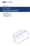
ENGINEERING
DATA
A N D S P E C I F I CAT I O N S
Marley AV
C O O L I N G TOW E R
AV Cooling Tower — Contents
2
Engineering Data
Schematic4
Support12
Hoisting Info
14
Freeze Prevention
15
Environmental16
Application17
Specifications / Base
Base18
Thermal Performance
19
19
Performance Warranty
Design Loading
19
Construction20
Mechanical Equipment
21
Fill, Louvers, and Drift Eliminators
22
Hot Water Distribution System
23
Casing, Fan Deck, Fan Cylinder, and Fan Guard
23
Access24
Cold Water Collection Basin
25
Specifications / Options
Stainless Steel Options
All Stainless Steel Cooling Tower
26
Fill, Louvers, and Drift Eliminators,
26
Hot Water Distribution System
26
Casing, Fan Deck, Fan Cylinder, and Fan Guard
27
Access27
Stainless Steel Collection Basin
28
Control Options
Fan Motor Starter Control Panel
Terminal Box
Vibration Limit Switch
Basin Heater
Fan Motor Variable Speed Drive
Single-Point Power Connection
28
28
29
30
30
31
Convenience and Safety Options
Hot Water Basin Access Platform
Ladder Extension
Ladder Safety Cage
Mechanical Equipment Access Platform
32
32
32
33
Miscellaneous Options
Fan Cylinder Extensions
Equalizer Flume Weir Gates
Marley Control Valve
Premium Efficiency Motor
FM Approval
Quiet Fan
Ultra Quiet Fan
Variable Water Flow Distribution
34
34
34
34
34
35
35
35
AV Cooling Tower
AV towers are galvanized steel, factory-assembled,
general purpose crossflow cooling towers, designed
to serve normal air conditioning and refrigeration
systems as well as light industrial loads. They evolve
from a singleflow concept of towers pioneered
by Marley in the 1950s, and incorporate all of the
design advancements that our customers have found
valuable. They represent the current state of the art
in this cooling tower category.
This booklet not only relates the language to use in
describing an appropriate AV cooling tower—but also
defines why certain items and features are important
enough to specify with the intention of insisting upon
compliance by all bidders. The left hand column of
pages 18 thru 35 provides appropriate text for the
various specification paragraphs, whereas the right
hand column comments on the meaning of the
subject matter and explains its value.
3
Pages 18 thru 25 indicate those paragraphs
which will result in the purchase of a basic cooling
tower—one that accomplishes the specified thermal
performance, but which will lack many operation—and
maintenance-enhancing accessories and features
that are usually desired by those people who are
responsible for the continued and continuing
operation of the system of which the tower is part.
It will also incorporate those standard materials
which testing and experience has proven to provide
acceptable longevity in normal operating conditions.
Pages 26 thru 35 provide paragraphs intended
to add those features, components, and materials
that will customize the tower to meet the user's
requirements.
AV Cooling Tower — Engineering Data: Schematic
4
Use this data for preliminary layouts only. Obtain
current drawing from your Marley sales representative.
UPDATE™ web-based selection software, available
at spxcooling.com/update provides AV cooling
tower model recommendations based on customer's
specific design requirements.
TOWER CL8" INLET
CL INLET
INLET FACE CL INLET
33/4
8" INLET PIPING
(BY OTHERS)
"
CL PIPING
MARLEY HC VALVE
(OPTION)
P
BASE OF
TOWER
SHORT RADIUS
ELBOW
(BY OTHERS)
8" INLET PIPING
(BY OTHERS)
INLET PIPING DETAILS
8" INLET CL
A
1'-115/16"
INLET FACE
11'-81/2"
H
INSTALLED
HEIGHT
CL
S
BASE OF
TOWER
HINGED ACCESS
DOOR
L
31/2"
CL
AV Cooling Tower — Engineering Data: Schematic
5
Shipping Weight
lb
Motor
hp
Design
Operating
Wt/Cell
lb
Weight/Cell
Heaviest
Section
117
3
8098
4248
—
138
5
8135
4285
—
71⁄2
8165
4315
—
167
10
8356
4506
—
Tower
Model
Nominal
Tons
note 2
note 3
AV6100A
AV6101A
AV6102A
157
AV6103A
Dimensions
L
8'-4"
H
12'-33⁄16"
A
8'-71⁄2"
S
11'-611⁄16"
P
12'-315⁄16"
AV6104A
195
15
8454
4604
—
AV6200A
172
5
10779
5316
—
AV6201A
193
71⁄2
10809
5346
—
AV6202A
213
10
10837
5374
—
AV6203A
229
15
11192
5729
—
AV6204A
259
20
11235
5772
—
AV6205A
275
25
11335
5872
—
11'-10"
12'-33⁄16"
12'-11⁄2"
11'-611⁄16"
12'-315⁄16"
AV6300A
190
7 ⁄2
9939
5467
3112
AV6301A
204
10
9969
5497
3142
AV6302A
232
15
10248
5776
3335
8'-4"
15'-211⁄16"
8'-71⁄2"
14'-63⁄16"
15'-37⁄16"
1
AV6303A
248
20
10344
5872
3431
AV6304A
264
25
10442
5970
3529
AV6400A
201
71⁄2
10573
5735
3112
AV6401A
217
10
10583
5765
3142
AV6402A
246
AV6403A
263
15
10836
6057
3335
20
10932
6153
3431
AV6404A
285
25
11029
6250
3528
3568
8'-4"
16'-715⁄16"
8'-71⁄2"
15'-117⁄16"
16'-811⁄16"
AV6405A
302
30
11069
6290
AV6500A
242
10
12019
6428
3513
AV6501A
270
15
12120
6529
3614
AV6502A
288
20
12468
6877
3836
9'-10"
16'-715⁄16"
10'-11⁄2"
15'-117⁄16"
16'-811⁄16"
AV6503A
311
25
12572
6981
3940
AV6504A
329
30
12615
7019
3978
AV6505A
345
40
12780
7189
4148
AV6600A
279
15
13247
6943
3990
AV6601A
305
20
13400
7036
4083
AV6602A
322
25
13774
7410
4326
AV6603A
343
30
13812
7448
4364
4534
11'-10"
15'-211⁄16"
12'-11⁄2"
14'-65⁄16"
15'-37⁄16"
AV6604A
355
40
13982
7618
AV6700A
293
15
14052
7267
3990
AV6701A
320
20
14145
7360
4083
AV6702A
344
25
14249
7464
4187
AV6703A
365
30
14578
7641
4364
AV6704A
390
40
14748
7811
4534
11'-10"
16'715⁄16"
12'-11⁄2"
15'-117⁄16"
16'-811⁄16"
NOTE
1
Use this bulletin for preliminary layouts only. Obtain current
drawings from your Marley sales representative. All table data is per
cell.
2Last numeral of model number indicates number of cells. Change as
appropriate for your selection.
3Nominal tons are based upon 95°F HW, 85°F CW, 78°F WB and 3
GPM/ton.
4Standard overflow is a 4" dia. connection in the collection basin wall
on the air inlet side of the tower. A 3" dia. drain connection is located
below the overflow. See page 7 for details
5Outlet sizes vary according to GPM and arrangement. See pages 6 and
7 for outlet sizes and details.
6Makeup water connection may be 1" or 2" dia., depending upon tower
heat load, water pressure, and desired connections. See page 6 for
additional information.
AV Cooling Tower — Engineering Data: Schematic
6
Use this data for preliminary layouts only. Obtain
current drawing from your Marley sales representative.
UPDATE™ web-based selection software, available
at spxcooling.com/update provides AV cooling tower
model recommendations based on customer's specific
design requirements.
TOWER CL8" INLET
CL INLET
INLET FACE CL INLET
33/4
8" INLET PIPING
(BY OTHERS)
"
CL PIPING
MARLEY HC VALVE
(OPTION)
P
BASE OF
TOWER
SHORT RADIUS
ELBOW
(BY OTHERS)
8" INLET PIPING
(BY OTHERS)
INLET PIPING DETAILS
8" INLET CL
A
1'-115/16"
INLET FACE
11'-81/2"
H
INSTALLED
HEIGHT
CL
S
BASE OF
TOWER
HINGED ACCESS
DOOR
L
31/2"
CL
AV Cooling Tower — Engineering Data: Schematic
7
Shipping Weight
lb
Motor
hp
Design
Operating
Wt/Cell
lb
Weight/Cell
Heaviest
Section
115
3
8232
4382
—
135
5
8283
4433
—
71⁄2
8383
4533
—
164
10
8532
4682
—
Tower
Model
Nominal
Tons
note 2
note 3
AV6100L
AV6101L
AV6102L
154
AV6103L
Dimensions
L
8'-4"
H
12'-33⁄16"
A
8'-71⁄2"
S
11'-611⁄16"
P
12'-315⁄16"
AV6104L
191
15
8653
4803
—
AV6200L
169
5
10926
5463
—
AV6201L
189
71⁄2
11027
5564
—
AV6202L
209
10
11068
5605
—
AV6203L
224
15
11344
5881
—
AV6204L
254
20
11412
5949
—
AV6205L
270
25
11584
6121
—
11'-10"
12'-33⁄16"
12'-11⁄2"
11'-611⁄16"
12'-315⁄16"
AV6300L
186
7 ⁄2
10157
5685
3330
AV6301L
200
10
10201
5729
3374
AV6302L
227
15
10449
5977
3536
8'-4"
15'-211⁄16"
8'-71⁄2"
14'-63⁄16"
15'-37⁄16"
1
AV6303L
243
20
10517
6045
3604
AV6304L
259
25
10692
6220
3779
AV6400L
197
71⁄2
10791
5953
3330
AV6401L
213
10
10815
5997
3374
AV6402L
241
AV6403L
258
15
11059
6280
3558
20
11105
6326
3604
AV6404L
279
25
11280
6501
3779
3859
8'-4"
16'-715⁄16"
8'-71⁄2"
15'-117⁄16"
16'-811⁄16"
AV6405L
296
30
11360
6581
AV6500L
237
10
12251
6660
3745
AV6501L
265
15
12345
6754
3839
AV6502L
282
20
12651
7060
4019
9'-10"
16'-715⁄16"
10'-11⁄2"
15'-117⁄16"
16'-811⁄16"
AV6503L
305
25
12821
7230
4189
AV6504L
322
30
12906
7310
4269
AV6505L
338
40
13202
7611
4570
AV6600L
273
15
13473
7169
4216
AV6601L
299
20
13578
7214
4261
15'-211⁄16"
12'-11⁄2"
14'-65⁄16"
15'-37⁄16"
AV6602L
316
25
14023
7659
4575
AV6603L
336
30
14103
7739
4655
4956
11'-10"
AV6604L
348
40
14404
8040
AV6700L
287
15
14278
7493
4216
AV6701L
314
20
14323
7538
4261
AV6702L
337
25
14493
7708
4431
AV6703L
358
30
14869
7932
4655
AV6704L
382
40
15171
8234
4957
11'-10"
16'715⁄16"
12'-11⁄2"
15'-117⁄16"
16'-811⁄16"
NOTE
1
Use this bulletin for preliminary layouts only. Obtain current
drawings from your Marley sales representative. All table data is per
cell.
2Last numeral of model number indicates number of cells. Change as
appropriate for your selection.
3Nominal tons are based upon 95°F HW, 85°F CW, 78°F WB and 3
GPM/ton.
4Standard overflow is a 4" dia. connection in the collection basin wall
on the air inlet side of the tower. A 3" dia. drain connection is located
below the overflow. See page 7 for details
5Outlet sizes vary according to GPM and arrangement. See pages 6 and
7 for outlet sizes and details.
6Makeup water connection may be 1" or 2" dia., depending upon tower
heat load, water pressure, and desired connections. See page 6 for
additional information.
AV Cooling Tower — Engineering Data: Schematic
8
Use this data for preliminary layouts only. Obtain
current drawing from your Marley sales representative.
UPDATE™ web-based selection software, available
at spxcooling.com/update provides AV cooling tower
model recommendations based on customer's specific
design requirements.
TOWER CL8" INLET
CL INLET
INLET FACE CL INLET
33/4
8" INLET PIPING
(BY OTHERS)
"
CL PIPING
MARLEY HC VALVE
(OPTION)
P
BASE OF
TOWER
SHORT RADIUS
ELBOW
(BY OTHERS)
8" INLET PIPING
(BY OTHERS)
INLET PIPING DETAILS
8" INLET CL
1'-115/16"
A
11'-81/2"
INLET FACE
H
INSTALLED
HEIGHT
CL
S
BASE OF
TOWER
HINGED ACCESS
DOOR
L
31/2"
CL
AV Cooling Tower — Engineering Data: Schematic
9
Shipping Weight
lb
Motor
hp
Design
Operating
Wt/Cell
lb
Weight/Cell
Heaviest
Section
117
3
8358
4508
—
138
5
8390
4540
—
71⁄2
8489
4639
—
167
10
8662
4812
—
Tower
Model
Nominal
Tons
note 2
note 3
AV6100C
AV6101C
AV6102C
157
AV6103C
Dimensions
L
8'-4"
H
14'-8 7⁄8"
A
S
8'-71⁄2"
P
11'-611⁄16"
12'-315⁄16"
AV6104C
195
15
8760
4910
—
AV6200C
172
5
10953
5490
—
AV6201C
193
71⁄2
11051
5588
—
AV6202C
213
10
11090
5627
—
AV6203C
229
15
11399
5936
—
AV6204C
259
20
11435
5972
—
AV6205C
275
25
11609
6146
—
1
11'-10"
14'-8 7⁄8"
12'-11⁄2"
11'-611⁄16"
12'-315⁄16"
AV6300C
190
7 ⁄2
10563
6091
3736
AV6301C
204
10
10609
6137
3782
AV6302C
232
15
10882
6410
3969
AV6303C
248
20
10926
6454
4013
AV6304C
264
25
11099
6627
4186
AV6400C
201
71⁄2
11196
6358
3735
AV6401C
217
10
11219
6401
3778
AV6402C
246
15
11470
6691
3969
AV6403C
263
20
11510
6731
4009
AV6404C
285
25
11687
6908
4186
AV6405C
302
30
11767
6988
4266
AV6500C
242
10
12619
7028
4113
AV6501C
270
15
12723
7132
4217
AV6502C
288
20
13019
7428
4387
AV6503C
311
25
13192
7601
4560
AV6504C
329
30
13277
7681
4640
AV6505C
345
40
13579
7988
4947
8'-4"
8'-4"
9'-10"
17'-8 1⁄2"
18'-111⁄16"
18'-111⁄16"
8'-71⁄2"
8'-71⁄2"
10'-11⁄2"
14'-63⁄16"
15'-117⁄16"
15'-117⁄16"
15'-37⁄16"
16'-811⁄16"
16'-811⁄16"
AV6600C
279
15
13805
7501
4548
AV6601C
305
20
13902
7538
4585
AV6602C
322
25
14349
7985
4901
AV6603C
343
30
14429
8065
4981
AV6604C
355
40
14736
8372
5288
AV6700C
293
15
14610
7825
4548
AV6701C
320
20
14647
7862
4585
AV6702C
344
25
14824
8039
4762
AV6703C
365
30
15195
8258
4981
AV6704C
390
40
15502
8565
5288
11'-10"
11'-10"
17'-81⁄2"
18'-1 ⁄16"
11
12'-11⁄2"
12'-1 ⁄2"
1
14'-65⁄16"
15'-11 ⁄16"
7
15'-37⁄16"
16'-8 ⁄16"
11
NOTE
1
Use this bulletin for preliminary layouts only. Obtain current
drawings from your Marley sales representative. All table data is per
cell.
2Last numeral of model number indicates number of cells. Change as
appropriate for your selection.
3Nominal tons are based upon 95°F HW, 85°F CW, 78°F WB and 3
GPM/ton.
4Standard overflow is a 4" dia. connection in the collection basin wall
on the air inlet side of the tower. A 3" dia. drain connection is located
below the overflow. See page 7 for details
5Outlet sizes vary according to GPM and arrangement. See pages 6 and
7 for outlet sizes and details.
6Makeup water connection may be 1" or 2" dia., depending upon tower
heat load, water pressure, and desired connections. See page 6 for
additional information.
AV Cooling Tower — Engineering Data: Piping
Outlet and Makeup Piping Details
Unless otherwise specified, single-cell towers normally
have a side-outlet suction appropriate for the design water
flow rate—see page 7. This usually assures the lowest
possible installed tower elevation. Side-suction connection
pipes extend roughly 3" outside the basin, and are beveled
for weld connection and also grooved for a mechanical
coupling.
10
Makeup Water Flow Required–gpm to maintain three (3) concentrations
Cooling "Range" (hot water° minus cold water°)
Tower
gpm
5º F
10º F
15º F
20º F
30º F
40º F
200
2
3
4
5
8
10
400
3
5
8
10
15
20
600
4
8
12
15
23
30
800
5
10
15
20
30
40
Outlet piping can be kept below the cold water basin
level by choosing a bottom outlet connection in lieu of the
side suction. Bottom outlet design conform to standard
class 125 ANSI pipe flange specifications. All outlet arrangements include easily removable debris screens.
1000
7
13
19
25
38
50
1500
10
19
29
38
57
75
2000
13
25
38
50
75
100
3000
19
38
57
75
113
150
4000
25
50
75
100
150
200
Multicell towers, intended to operate together as a common unit, are joined by steel flumes between the collection
basins. These flumes equalize the operating water level
between basins and also provide a flow passage from cells
not equipped with outlets or makeup valves, often eliminating the need to specify an outlet and makeup valve for
each cell on a multicell installation. Refer to sales drawings
to obtain flow values of suctions and bottom outlets for
multicell installations.
5000
32
63
94
125
188
250
6000
38
75
113
150
225
300
8000
50
100
150
200
300
400
The best choice for a tower used with a remote or
indoor storage tank—see page 11—or on a concrete cold
water basin is usually a bottom outlet, with or without
screen.
NOTE
• If circulating water is to be maintained at 2 concentrations instead of 3,
multiply table gpm values by 1.36 before sizing makeup valve.
Makeup Valve Flow Capacities–GPM
Pressure at Valve Inlet
while flowing–psig
1" Diameter
Valve
10
56
90
20
78
120
30
92
143
40
106
160
50
117
167
Makeup
The amount of water constantly evaporated from a
cooling tower varies directly with the heat load applied. In
addition to evaporation, water is normally lost to the blowdown (bleed-off) necessary to maintain dissolved solids
concentration at an acceptable level in the circulating water
system.
The AV tower is equipped with a float-operated, mechanical makeup valves to automatically replenish this lost
water. The following tables, calculated for a concentration
of 3 times normal, indicate the rate of water loss, and the
size of valve(s) required. If your installation’s cold water
basin will drain by gravity to a remote storage tank, or if
you plan a separate means of controlling makeup water,
we offer a price reduction for deleting the makeup valve.
NOTE
2" Diameter
Valve
• If makeup water pressure exceeds 50 psig, use pressure reducer ahead
of valve.
• For flow requirements exceeding the above limitations, use multiples of
the same size valve.
AV Cooling Tower — Engineering Data: Piping
11
WELDING
BEVEL
MECHANICAL
COUPLING GROOVE
SUCTION HOOD
REMOVABLE
TRASH SCREEN
103/8"
SUCTION CONNECTION
SEE TABLE FOR SIZE
13/16"
BASE OF
TOWER
OUT OF TOWER
SECTION
SIDE-OUTLET SUCTION CONNECTION
OUTLET
SEE TABLE FOR SIZE
TOWER COLLECTION
BASIN FLOOR
Maximum gpm Outlet
REMOVABLE
TRASH SCREEN
OUTLET
CONNECTION
Side Suction
pump flow
air inlet face
Outlet
Dia.
2 1/16"
Section
NOTE BOTTOM OUTLET IS
ALSO AVAILABLE WITHOUT
TRASH SCREEN.
BASE OF
TOWER
BOTTOM OUTLET CONNECTION
13/4"
B
Bottom Outlet
pump flow
w/anti-vortex
plate or
gravity flow
All Models
All Models
All Models
—
—
71
164
6"
—
—
162
372
8"
1595
1568
287
658
10"
2562
—
453
1038
—
644
1476
—
788
1807
14"
CL TOWER
AV62
AV66
and
AV67
Bottom Outlet
pump flow
4"
12"
A
AV61
and
AV63
thru
AV65
Side Suction
pump flow
cased face
—
3500
—
MAKEUP
1" MNPT
OVERFLOW
4" FNPT
Dimensions
Tower Model
DRAIN
3" FNPT
1'-2 3/8" 2'-7 1/4"
3 5/8"
BASE OF
TOWER
AIR INLET FACE
2"
OUT OF TOWER
SECTION
A
B
AV61
1'-9"
3'-10"
AV62
3'-6"
5'-7"
AV63
1'-9"
3'-10"
AV64
1'-9"
3'-10"
AV65
2'-6"
4'-7"
AV66
3'-6"
5'-7"
AV67
3'-6"
5'-7"
OVERFLOW, DRAIN, AND MAKEUP CONNECTION
NOTE
1 F
or gravity-flow situations (as to an indoor tank), use bottom outlet.
Side outlet suction is not recommended for gravity flow.
2 G
PM limits are based on single-cell or multicell towers with a single outlet
per cell. For multicell towers connected with collection basin flumes and
less than one outlet per tower cell consult your Marley sales representative
for more specific information.
AV Cooling Tower — Engineering Data: Support
12
L
L
OVERALL OF BASIN
OVERALL OF BASIN
D
1"
CL ANCHOR
ANCHOR CL
BOLT
BOLT
2"
A
HOLES FOR
1/2" DIA. ANCHOR
BOLTS 4 REQD
HOLES FOR
1/2" DIA. ANCHOR
BOLTS 4 REQD
11'-8 1/2" 11'-4 1/2"
BOLT
BOLT
CL ANCHOR
CL ANCHOR
11'-8 1/2" 11'-4 1/2"
2"
TOWER COLLECTION
BASIN—AIR INLET FACE
SUPPORTING STEEL
SUPPORTING STEEL
OPTION ONE
Dimensions
B
2"
TOWER COLLECTION
BASIN—AIR INLET FACE
OPTION TWO
L
D
Design Operating
Weight/Cell
lb
AV6100
8'-4"
8'-2"
8435
2815
AV6200
11'-10"
11'-8"
11314
3824
AV6300
8'-4"
8'-2"
10370
3436
AV6400
8'-4"
8'-2"
11024
3636
AV6500
9'-10"
9'-8"
12709
4203
AV6600
11'-10"
11'-8"
13912
4709
AV6700
11'-10"
11'-8"
14791
4939
Tower Model
1"
ANCHOR CL
BOLT
CL ANCHOR
ANCHOR CL
BOLT
2"
ANCHOR CL
BOLT
BOLT
D
1"
1"
Design Operating
Load at Anchor
lb
TOWER
COLLECTION
BASIN
1"
SUPPORT
BY OTHERS
1/2" WASHER REQD
BY OTHERS
NORMAL
GAUGE
SECTION A
AV Cooling Tower — Engineering Data: Support
13
L
L
OVERALL OF BASIN
OVERALL OF BASIN
D
1"
BOLT
D
1"
1"
ANCHOR CL
BOLT
CL ANCHOR
C
1"
ANCHOR CL
BOLT
CL ANCHOR
BOLT
1'-10 1/4"
MAX
ANCHOR CL
BOLT
3'-6"
ANCHOR CL
BOLT
MAX
HOLES FOR
1/2" DIA. ANCHOR
BOLTS 4 REQD
HOLES FOR
1/2" DIA. ANCHOR
BOLTS 4 REQD
11'-8 1/2"
11'-8 1/2" 8'-0"
MIN
8'- 0 1/2"
BOLT
CL ANCHOR
BOLT
CL ANCHOR
MIN
1'-10 1/4"
MAX
C
2"
TOWER COLLECTION
BASIN—AIR INLET FACE
TOWER COLLECTION
BASIN—AIR INLET FACE
SUPPORTING STEEL
SUPPORTING STEEL
OPTION FOUR
OPTION THREE
3 1/2" MAX TO CLEAR LARGEST
BOTTOM OUTLET FLANGE
MINIMUM BEARING WIDTH MUST BE
PROVIDED BY BEAM FLANGE OR BEARING
PLATE AT EACH ANCHOR BOLT LOCATION.
TOWER
COLLECTION
BASIN
6"
TOWER
COLLECTION
BASIN
1/2"
WASHER REQD
BY OTHERS
SUPPORT
BY OTHERS
NORMAL
GAUGE
B
SUPPORT
BY OTHERS
1/2" WASHER REQD
BY OTHERS
NORMAL
GAUGE
ANCHOR BOLT LOCATION RELATIVE
TO BEAM ORIENTATION IS OPTIONAL
VIEW B
VIEW C
NOTE
1Use this bulletin for preliminary layouts only. Obtain current drawings
from your Marley sales representative for final design.
2Grillage anchorage Option Three is not intended for use with the Bottom Outlet Option.
3Multicell installations shall conform to arrangements shown. The standard spacing between the side face anchor bolts is 51⁄2".
4Purchaser to provide tower support complete with holes and anchor
bolts. Do not use studs! Anchor points must be framed flush and level at
top.
5Design operating weight occurs with collection basin full to overflow
level. Actual operating weight varies with GPM and piping scheme.
6Anchorage for Supporting Steel Options One and Two are designed
for 30 psf wind and/or .7g seismic loading for AV61 and AV62, 20
psf wind and/or .3g for AV63 thru AV65 and 20 psf wind and/or .46g
for AV66 and AV67. Anchorage capacity for Supporting Steel Options
Three and Four are less and will vary with the beam spacing.
7Tower may be placed on a flat concrete slab. Side outlet must be
specified. See pages 6 and 7 and consult your Marley application sales
representative.
8Tower may be supported from piers at each anchor bolt location, as a
support alternative.
AV Cooling Tower — Engineering Data: Hoisting Information
14
OFFSET REQUIRED FOR
BALANCED LIFT
CL TOWER
10'-0 MIN
SLING LENGTH
CL TOWER
11'-9"
MIN
11'-8"
MIN
15'-0 MIN
SLING LENGTH
NOTE
1 All hoisting clip holes are 11⁄4".
2 Overall length of shackle pins should not exceed 51⁄4".
3 For overhead lifts or where additional safety is required, add slings beneath the tower unit.
AV Cooling Tower — Engineering Data: Freeze Prevention
When the ambient air temperature falls below 32°F, the
water in a cooling tower can freeze. Marley Technical Report
#H-003 "Operating Cooling Towers in Freezing Weather"
describes how to prevent freezing during operation. Available
at spxcooling.com or ask your Marley sales representative for
a copy.
During shutdown, water collects in the cold water basin
and may freeze solid. You can prevent freezing by adding heat
to the water left in the tower—or, you can drain the tower and
all exposed pipework at shutdown.
Electric Basin Heaters
An automatic basin water heater system is available consisting of the following components:
• Stainless steel electric immersion heater(s).
Threaded couplings are provided in the side of the
—
collection basin.
• N EMA 4 enclosure containing:
—Magnetic contactor to energize heater.
—Transformer to convert power supply to 24 volts for
control circuit.
Solid state circuit board for temperature and
—
low-water cutoff.
Enclosure may be mounted on the side of the tower.
• Control probe in the collection basin to monitor water
temperature and level.
Heater components are normally shipped separately for
installation by others.
ote: any exposed piping that is still filled with water at
N
shutdown—including the makeup water line—should be
electrically traced and insulated (by others).
15
Steam Jet Basin Heater
Penberthy Houdaille bronze steam jet heaters (1⁄4" to 3⁄4")
are available for freeze protection (installation by others). Injectors install in a coupling provided in the side of the collection
basin. Live steam, as required, is injected directly into the water. Condensed steam adds water to the basin, and the excess
will exit the overflow of the tower.
Indoor Storage Tank
With this type of system, water flows from an indoor tank,
through the load system, and back to the tower, where it is
cooled. The cooled water flows by gravity from the tower to
the tank located in a heated space. At shutdown, all exposed
water drains into the tank, where it is safe from freezing.
The amount of water needed to successfully operate
the system depends on the tower size and GPM and on the
volume of water contained in the piping system to and from
the tower. You must select a tank large enough to contain
those combined volumes—plus a level sufficient to maintain a
flooded suction on your pump. Control makeup water according to the level where the tank stabilizes during operation.
AV Cooling Tower — Engineering Data: Operational and Environment Awareness
Sound Control
Sound produced by an AV Series tower operating in
an unobstructed environment will meet all but the most
restrictive noise limitations—and will react favorably to natural
attenuation. Where the tower has been sized to operate within
an enclosure, the enclosure itself will have a damping effect
on sound. Sound also declines with distance—by about 6 dBA
each time the distance doubles.
All standard AV cooling towers are equipped with low
sound fans. This in combination with zero-splash crossflow
film-fill results in a line of towers capable of meeting most
noise limitations. Where noise at a critical point is likely
to exceed an acceptable limit, several other options are
available—listed below in ascending order of cost impact:
• The Marley "Quiet Package" includes the affordable
Quiet Fan mechanical option, optimized to achieve
the lowest possible sound levels while maintaining
efficiency.
• A Marley Variable Speed Drive automatically minimizes
the tower’s noise level during periods of reduced load
and/or reduced ambient temperature without sacrificing
the system’s ability to maintain a constant cold water
temperature. This is a relatively inexpensive solution,
and can pay for itself quickly in reduced energy costs.
The natural nighttime reduction in wetbulb temperature
makes this a very feasible solution in most areas of the
world. It also eliminates fan cycling. In combination with
a Marley Quiet Package, the Marley Variable Speed
Drive is capable of meeting all but the most restrictive
noise limitations.
• For more severe cases requiring the lowest possible
fan sound levels the Marley “Ultra Quiet” fan option is
now available on most AV models. Tower height will
increase—obtain current sales drawings from your
Marley sales representative for accurate dimensions.
• Extreme cases may require inlet and discharge sound
attenuator sections—however, the static pressure loss
imposed by attenuators may necessitate an increase in
tower size. This is the least desirable approach because
of the significant cost impact—and because of the
obstruction to normal maintenance procedures.
Although not an industry requirement, all published sound
data on Marley cooling towers are in accordance with CTI
ATC128 so you can be assured of sound data accuracy.
Enclosure
Occasionally, cooling towers are located inside architectural
enclosures for aesthetic reasons. Although AV Series towers
adapt well to enclosures, the designer must realize the
potential impact of a poorly arranged enclosure on the tower’s
performance and operation. The designer must take care to
provide generous air inlet paths, and the tower’s fan cylinder
discharge height should not be lower than the elevation of the
top of the enclosure. Obtain a copy of Marley Technical Report
#H-004 "External Influences on Cooling Tower Performance"
from your Marley sales representative.
16
As suggested in the aforementioned Technical Report,
it may also be advisable to specify a design wet-bulb
temperature 1°F higher than normal to compensate for
potential recirculation initiated by the enclosure. You’ll
benefit from discussing your project with your Marley sales
representative.
System Cleanliness
Cooling towers are very effective air washers. Atmospheric
dust able to pass through the relatively small louver
openings will enter the circulating water system. Increased
concentrations can intensify system maintenance by clogging
screens and strainers—and smaller particulates can coat
system heat transfer surfaces. In areas of low flow velocity—
such as the cold water basin—sedimentary deposits can
provide a breeding ground for bacteria.
In areas prone to dust and sedimentation, you should
consider installing some means for keeping the cold water
basin clean. Typical devices include side stream filters and a
variety of filtration media.
Water Treatment
To control the buildup of dissolved solids resulting from
water evaporation, as well as airborne impurities and biological
contaminants including Legionella, an effective consistent
water treatment program is required. Simple blowdown may
be adequate to control corrosion and scale, but biological
contamination can only be controlled with biocides.
An acceptable water treatment program must be
compatible with the variety of materials incorporated in a
cooling tower—ideally the pH of the circulating water should
fall between 6.5 and 8.0. Batch feeding of chemicals directly
into the cooling tower is not a good practice since localized
damage to the tower is possible. Specific startup instructions
and additional water quality recommendations can be found in
the AV Series User Manual which accompanies the tower and
also is available from your local Marley sales representative.
For complete water treatment recommendations, consult a
competent, qualified water treatment supplier.
CAUTION
The cooling tower must be located at such distance
and direction to avoid the possibility of contaminated
discharge air being drawn into building fresh air
intake ducts. The purchaser should obtain the
services of a Licensed Professional Engineer or
Registered Architect to certify that the location of
the cooling tower is in compliance with applicable air
pollution, fire and clean air codes.
AV Cooling Tower — Engineering Data: Application
17
Typical Applications
Alternative Selections
The AV cooling tower can be used in normal applications
requiring cold water for the dissipation of heat. This includes
condenser water cooling for air conditioning, refrigeration, and
thermal storage systems, as well as their utilization for freecooling in all of those systems. They are also used in the cooling of jacket water for engines and air compressors, and are
widely applied to dissipate waste heat in a variety of industrial
and manufacturing processes.
In addition to the AV Series, we offer a full scope of Marley
products in various designs and capacities to meet the special
demands of specific applications.
Choosing the all stainless steel construction option, the AV
can be confidently applied in unusually corrosive processes
and operating environments. However, no single product line
can answer all problems, and selective judgement should be
exercised in the following situations
Applications Requiring Alternative Cooling
Tower Selections
Certain types of applications are incompatible with any
cooling tower with PVC film fill—whether an AV or other
manufacturer's cooling tower of similar design. PVC is subject
to distortion in high water temperatures, and the narrow passages typical of film-type fill are easily clogged by turbid or
debris-laden water. Some of the applications, which call for
alternative tower designs are:
• E
thylene glycol content—can plug fill passages as slime
and algae accumulate to feed on the available organic
materials.
• F
atty acid content—found in processes such as soap
and detergent manufacturing and some food processing, fatty acids pose a serious threat for plugging fill
passages.
• P
articulate carry over—often found in steel mills and
cement plants, can both cause fill plugging, and can
build up to potentially damaging levels on tower structure.
• P
ulp carry over—typical of the paper industry and
food processing where vacuum pumps or barometric
condensers are used. Causes fill plugging which may be
intensified by algae.
spxcooling.com—visit us on the web for a complete list of
products, services, publications and to find your nearest sales
representative.
Corrosion Resistance
• Q
uadraFlow®—fiberglass and stainless steel construction assures long service life in virtually any environment.
Five-year full product warranty. Efficient PVC film fill.
Uniquely different and architecturally attractive.
• S
igma™—available in wood, fiberglass, HDG steel or
stainless steel structure. Field-erected for medium to
large projects. Available in a wide range of sizes.
Efficient PVC film fill.
Splash Fill
• NC® alpha—available in galvanized steel and stainless
steel, with splash-type fill. Excellent in “dirty water” applications.
AV Cooling Tower — Specifications: Base
Specifications
1.0
Base:
1.1
Provide an induced draft, crossflow type,
factory assembled, film fill, industrial duty,
galvanized steel cooling tower situated as
shown on the plans. The limiting overall
dimensions of the tower shall be _____ ft
wide, _____ ft long, and _____ ft high to
the top of the fan guard. Total operating
power of all fans shall not exceed _____
hp, consisting of ___ @ ___ hp motor(s).
Tower shall be similar and equal in all
respects to Marley Model ________.
1.2
The cooling tower shall be designed
for quiet operation, and shall produce an overall level of sound not
higher than _______ dB(A) measured at _______ ft from the location:
______________________. Sound levels
shall be measured with a Type 1 (precision) system and in full conformance
with ATC-128 test code published by the
Cooling Technology Institute (CTI). The
measurement system shall have a realtime frequency analyzer and separate
microphones with an overall tolerance
+/- 3 dB. All low sound options shall be
CTI Certified for thermal performance.
18
Specification Value
■ Your specification base establishes the type, configuration, base material,
and physical limitations of the cooling tower to be quoted. During the
planning and layout stages of your project, you will have focused your
attention on a cooling tower selection that fits your space allotment, and
whose power usage is acceptable. Limitations on physical size and total
operating horsepower avoid the introduction of unforeseen operational
and site-related influences. Specifying the number of cells, and the maximum fan hp/cell will work to your advantage.
The benefit of crossflow towers is that they are inherently easy to operate, access, and maintain. Unlike counterflow towers, they have a spacious, full height plenum for easy access to all of the tower's internal
components, and the water distribution system is readily open to view
and cleaning.
If your preference is for a stainless steel tower, or if your water or air
quality suggests that the use of stainless steel is prudent, see stainless
steel options on page 26.
Ladder and access platform
are optional accessories. See
Page 24 for specification
wording.
The ladder can be located on
either end of the platform by
simple field rearrangement of
handrails and posts.
AV Cooling Tower — Specifications: Base
2.0
Thermal Performance:
2.1 The tower shall be capable of cooling
_____ gpm of water from ____ °F to
_____ °F at a design entering air wet-bulb
temperature of _____ °F, and its thermal
rating shall be Certified by the Cooling
Tower Institute.
3.0
Performance Warranty:
3.1
CTI Certification notwithstanding,
the cooling tower manufacturer shall
guarantee that the tower supplied
will meet the specified performance
conditions when the tower is installed
according to Plans. If, because of
a suspected thermal performance
deficiency, the Owner chooses to conduct
an on-site thermal performance test
under the supervision of a qualified,
disinterested third party in accordance
with CTI or ASME standards during
the first year of operation; and if the
tower fails to perform within the limits
of test tolerance; then the cooling tower
manufacturer will pay for the cost of
the test and will make such corrections
as are appropriate and agreeable to
the Owner to compensate for the
performance deficiency.
4.0
Design Loading:
4.1
The tower structure and anchorage
shall be designed to withstand a wind
load of 20 psf (957 Pa), as well as .3g
seismic load while operating. The tower
shall be designed to withstand shipping
and hoisting loads of 2g horizontal and
3g vertical. Handrails, where specified,
shall be capable of withstanding a 200
lb. (890 N) concentrated live load in
any direction, and shall be designed in
accordance with OSHA guidelines. Fork
lift slots shall be provided in the basin
side supports to allow handling of the
tower at grade level.
Specification Value
■ CTI Certification means that the tower
has been tested under operating conditions and found to perform as rated by
the manufacturer under those circumstances. It assures the buyer that the
tower is not intentionally or inadvertently
undersized by the manufacturer.
■ However,
CTI certification alone is not sufficient to assure you that the
tower will perform satisfactorily in your situation. Certification is established under relatively controlled conditions, and towers seldom operate
under such ideal circumstances. They are affected by nearby structures,
machinery, enclosures, effluent from other towers, etc. Responsible and
knowledgeable bidders will take such site-specific effects into consideration in selecting the tower—but the specifier must insist by the written
specification that the designer/manufacturer guarantee this “real world”
performance. Any reluctance on the part of the bidder should cause you
some concern.
95ϒ
90ϒ
85ϒ
COLD WATER TEMP. (ϒF)
Specifications
19
80ϒ
5ϒF RANGE
10ϒF RANGE
15ϒF RANGE
75ϒ
70ϒ
65ϒ
60ϒ
55ϒ
50ϒ
55ϒ
60ϒ
65ϒ
70ϒ
75ϒ
80ϒ
WET BULB TEMP. (ϒF)
■ The
design wind and seismic loads at the left are the minimum allowables for any model in the line under accepted design standards. Some
models can withstand greater loads as listed below:
Model
AV61 and AV62
AV63 thru AV65
AV66 and AV67
Wind
30 psf
20 psf
20 psf
Seismic
.7g
.3g
.46g
If your application requires higher loads, consult your Marley sales representative. These standards give you assurance that the tower can be
shipped, handled, hoisted and ultimately operated in a normal cooling tower
environment.
AV Cooling Tower — Specifications: Base
Specifications
5.0
Construction:
5.1
Except where otherwise specified, all
components of the cooling tower shall be
fabricated of heavy-gauge steel, protected
against corrosion by G-235 galvanizing.
The tower shall be capable of withstanding water having a pH of 6.5 to 8.0; a
chloride content (NaCl) up to 500 ppm; a
sulfate content (SO4) up to 250 ppm; a
calcium content (CaCO3) up to 500 ppm;
and silica (SiO2) up to 150 ppm. The circulating water shall contain no oil, grease,
fatty acids, or organic solvents. Fiberglass
casing, polyurethane barriers, and thermosetting hybrids and the components that
are adhered to the sheet metal surface,
shall be considered non-recyclable and
not allowed.
5.2
The specifications, as written, are intended to indicate those materials that will be
capable of withstanding the above water
quality in continuing service, as well as the
loads described in paragraph 4.1. They
are to be regarded as minimum requirements. Where component materials peculiar to individual tower designs are not
specified, the manufacturers shall take
the above water quality and load carrying
capabilities into account in the selection
of their materials of manufacture.
5.3
The tower shall include all design and
material modifications necessary to meet
the requirements of Factory Mutual. The
product proposed shall be listed in the FM
Approval Guide, latest edition.
Specification Value
■ In the history of cooling towers, no other coating for carbon steel has
exhibited the success and longevity of galvanization in exposure to the
normal cooling tower water quality defined at left. No paints or electrostatically applied coatings, however exotic they may be, can approach
galvanization's history of success.
Except for those unusual operating situations where the circulating water
may be so laden with suspended solids, algae, fatty acids, product fibers,
active organisms reflected in BOD, and the like that plugging of the fill
is a probability, reasonable attention to the construction materials and/or
their coatings is all that is normally required.
If your preference is for a stainless steel tower, or if your water or air
quality suggests that the use of stainless steel is prudent, see stainless
steel options on page 26.
Factory Assembly
20
AV Cooling Tower — Specifications: Base
Specifications
6.0
Specification Value
Mechanical Equipment:
6.1Fan(s) shall be propeller type, incorporating
heavy duty aluminum alloy blades attached
to galvanized hubs with stainless steel
U-bolts and hardware. Blades shall be
attached to hubs with stainless steel
hardware, and shall be individually
adjustable. Fan(s) shall be driven through
an industrial grade system of V-belts,
pulleys, and tapered roller bearings.
Bearings shall be rated at 50,000 hours, or
greater.
6.2
Motor(s) shall be 40 Hp maximum,
Totally Enclosed, 1.15 service factor,
variable torque, and specially insulated for
cooling tower duty. Speed and electrical
characteristics shall be 1800 rpm, singlewinding, ___ phase, ____ Hz, ____ volts.
6.3
The fan and fan drive assembly for each
cell shall be supported by a rigid, welded,
hot dip galvanized steel structural support
that resists misalignment. The mechanical
equipment assembly shall be warranted
against any failure caused by defects in
materials and workmanship for no less
than five (5) years following the date of
tower shipment. This warranty is limited to
the fan, fan shaft, bearings, and mechanical equipment support. The motor, motor
components, sheaves and belt(s) are warranted by their manufacturer.
fans require only half the operating hp of blower-type fans.
■ Propeller-type
However, they should be readily adjustable to permit compensation for
job site conditions that may tend to overload the motor. The fans of one
manufacturer require the purchase of special positioners for each increment of fan blade pitch.
Unless otherwise specified, motor speed will be 1800 RPM in 60 Hertz
areas and 1500 RPM in 50 Hertz areas. If you prefer the operating flexibility of two-speed operation, please specify the RPM to be 1800/900
(1500/750 in 50 Hertz regions). Incidentally, two speed motors are a far
better choice than separate “pony” motors which simply double the problems indicated above.
If your preference is for a stainless steel tower, or if your water or air
quality suggests that the use of stainless steel is prudent, see stainless
steel options on page 26.
21
AV Cooling Tower — Specifications: Base
Specifications
22
Specification Value
7.0
Fill, Louvers, and Drift Eliminators:
7.1
Fill shall be film-type, thermoformed of
PVC, with louvers and eliminators formed
as part of each fill sheet. Fill shall be
suspended from hot-dip galvanized structural tubing supported from the tower
structure, and shall be elevated above the
floor of the cold water basin to facilitate
cleaning. The air inlet face of the tower
shall be free of water splash-out.
■ Louvers
integral with the fill keep the flowing water within the confines
of the fill. The separate external louvers used by others permit water to
escape the fill and form ice or produce an unsightly situation adjacent to
the tower. If you plan to use your tower in the wintertime, particularly for
free cooling, integral louvers will put your operating concerns to rest.
7.2
Drift eliminators shall be PVC, triple-pass,
and shall limit drift losses to no more than
0.005% of the design GPM flow rate.
■ Drift
rate varies with design
water loading and air rate, as
well as drift eliminator depth
and number of directional
changes. A drift rate of 0.001%
is readily available on many standard models. If a lower rate is
required, please discuss with
your Marley sales representative.
Drift Eliminators
Louvers
Fill Sheets
AV Cooling Tower — Specifications: Base
Specifications
8.0
Hot Water Distribution System:
8.1
An open basin above the bank of fill shall
receive hot water piped to each cell of
the tower. These distribution basins shall
be installed and sealed at the factory with
bolted connections. Tap screws shall not
be allowed. The basin shall , and shall be
equipped with removable, galvanized steel
covers to keep out leaves and debris, and
to retard the growth of algae. The water
distribution system shall be accessible
and maintainable during tower fan and
water operation.
8.2
Each basin shall include an inlet hole
and bolt circle to accept a 125# flange
connection per ANSI B16.1. Removable,
interchangeable polypropylene nozzles
installed in the floor of these basins shall
provide full coverage of the fill by gravity
flow.
8.3
Heavy-duty flow-regulator valves shall
be provided at the hot-water inlet connections. These valves shall be disc-type,
with cast iron bodies and stainless steel
operating stems. There shall be a locking
handle to maintain the valve setting in
any position. Valves shall be right-angle
configuration, precluding the need for
inlet elbows.
8.4
Variable Water Flow Distribution - The
water distribution system shall be
equipped with a method to operate under
variable flow conditions while maintaining
a uniform air-side pressure drop through
the fill to maximize cooling efficiency and
minimize the risk of ice and scale formation in the fill. System must accommodate
flow rates down to _______% of design
flow.
9.0
Casing, Fan Deck, Fan Cylinder,
and Fan Guard:
9.1
The casing and fan deck shall be
heavy-gauge galvanized steel, and shall
be capable of withstanding the loads
described in paragraph 4.1. Fan cylinder
extensions shall be provided to elevate
the fan discharge to a height of ___ ft.
(___ m) above the top of the standard fan
cylinder. The fan cylinder shall be molded
FRP, and shall be through-bolted to the
fan deck to provide a consistently stable
Specification Value
distribution basins are a feature of crossflow type towers,
■ Gravity-flow
resulting in operating pump heads of from 10 to 20 feet less than that
encountered in counterflow towers with pressurized spray systems. Also,
these basins are out where they can be easily inspected—even maintained—while the tower is in operation. Spray systems of counterflow
towers, sandwiched between the top of the fill and the drift eliminators,
are extremely awkward to access and maintain.
If your preference is for a stainless steel tower, or if your water or air
quality suggests that the use of stainless steel is prudent, see stainless
steel options on page 26.
23
AV Cooling Tower — Specifications: Base
Specifications
Specification Value
operating shroud for the fan. The top of
the fan cylinder shall be equipped with
a conical, non-sagging, removable fan
guard, fabricated of welded 5/16" and 7
gauge rods, and hot-dip galvanized after
fabrication.
10.0
Access:
10.1
Large galvanized steel access doors 30"
(762 mm) wide and a minimum of 42"
(1067 mm) high shall be located in both
endwalls for entry into the cold water
basin and fan plenum area. Access doors
shall be operable from inside as well as
outside the tower.
10.2
Provide an external platform near the top
of the louver face for access to the hot
water distribution system. The platform
shall be galvanized steel bar grating, supported by galvanized steel framework
attached to the tower. The platform shall
be surrounded by a handrail, kneerail, and
toeboard. A permanently attached 1'-6"
(457.2 mm) wide aluminum ladder with
3" (76.2 mm) I-beam side rails and 1.25"
(31.8 mm) diameter serrated rungs shall
extend from the base of the tower to the
top of the handrail.
10.3
Provide a ladder extension for connection
to the foot of the external ladder. This
extension shall be long enough to rise
from the roof (grade) level. The installing
contractor shall be responsible for cutting
the ladder to length; attaching it to the
foot of the tower ladder; and anchoring it
at its base.
10.4
A heavy gauge galvanized steel safety
cage shall surround the ladder, extending
from a point approximately 7'-0" (2134
mm) above the foot of the ladder to
the top of the distribution basin access
platform handrail.
access doors on competitive towers may be
■ The
18" wide or smaller, which is unreasonably small for
a human being. Specifying the size of the door will
cause those bidders to take exception, alerting you
to a potential maintenance headache. Two doors are
standard on all towers so that access between cells
of multicell towers is assured.
24
AV Cooling Tower — Specifications: Base
Specifications
10.5
Provide an internal platform approximately
7' (2134 mm) below the level of the fan
for access to the mechanical equipment.
The platform shall be galvanized steel
bar grating, supported by galvanized steel
framework attached to the tower. The
platform shall be surrounded by a handrail and kneerail. A permanently attached
1'-6" (457.2 mm) wide aluminum ladder
with 3" (76.2 mm) I-beam side rails and
1.25" (31.8 mm) diameter serrated rungs
shall extend from the cold water basin to
the top of the handrail.
10.6
Air Inlet Screens - The air inlet faces of
the tower shall be covered by 1" mesh
hot-dipped galvanized welded wire
screens. Screens shall be secured to
removable galvanized U-edge frames.
11.0
Cold Water Collection Basin:
11.1
The collection basin shall be G-235
galvanized steel and assembled with
bolted connections. Tap screws shall not
be allowed. The cold water basin shall
be heavy-gauge galvanized steel, and
The basins shall include the number and
type of suction connections required to
accommodate the outflow piping system
shown on the Plans. Suction connections shall be equipped with galvanized
debris screens. A factory-installed, floatoperated, mechanical makeup valve shall
be included. A 3" (76.2 mm) diameter
drain and a 4" (101.7 mm) diameter
overflow shall be provided in each cell
of the tower. The basin shall include a
depressed section into which accumulated silt can be flushed to permit cleaning.
The basin floor adjacent to the depressed
section shall slope toward the depressed
section to prevent buildup of silt under
the fill area. Towers of more than one cell
shall include flumes for flow and equalization between cells.
Specification Value
from side suctions and bottom outlets to accommodate a signifi■ Choose
cant variety of piping schemes. Unless so specified, the tower you may
be asked to approve may only be available with one type of suction connection, requiring you to redesign your piping layout.
If your preference is for a stainless steel tower, or if your water or air
quality suggests that the use of stainless steel is prudent, see stainless
steel options on page 26.
25
AV Cooling Tower — Specifications: Options
Specifications
Stainless Steel Options
All Stainless Cooling Tower
1.1
Replace paragraph 1.1 with the
following: Provide an induced draft,
crossflow type, factory assembled, film
fill, industrial duty, stainless steel cooling
tower situated as shown on the plans.
The limiting overall dimensions of the
tower shall be _____ ft wide, _____ ft
long, and _____ ft high to the top of the
fan guard. Total operating power of all
fans shall not exceed ____ Hp, consisting
of ___ @ ___ Hp motor(s). Tower shall be
similar and equal in all respects to Marley
Model ________.
5.1
Replace paragraph 5.1 with the following: Except where otherwise specified,
all components of the cooling tower shall
be fabricated of 301L stainless steel. The
tower shall be capable of withstanding
water having a chloride content (NaCl) up
to 750 ppm; a sulfate content (SO4) up
to 1200 ppm; a calcium content (CaCO3)
up to 800 ppm; and silica (SiO2) up to
150 ppm. The circulating water shall contain no oil, grease, fatty acids, or organic
solvents. Fiberglass casing, polyurethane
barriers, and thermosetting hybrids and
the components that are adhered to the
sheet metal surface, shall be considered
non-recyclable and not allowed.
Fill, Louvers, and Drift Eliminators:
7.1
Replace paragraph 7.1 with the
following: Fill shall be film-type,
thermoformed of PVC, with louvers
and eliminators formed as part of each
fill sheet. Fill shall be suspended from
stainless steel structural tubing supported
from the tower structure, and shall be
elevated above the floor of the cold water
basin to facilitate cleaning. The air inlet
face of the tower shall be free of water
splash-out.
Hot Water Distribution System:
8.1
Replace paragraph 8.1 with the
following: An open 301L stainless steel
basins (one above each bank of fill) shall
receive hot water piped to each cell of
the tower. These basin components shall
be installed and sealed at the factory
Specification Value
■
Where water quality falls outside the limits indicated in Paragraph 5.1, an
all-stainless tower is worthy of your consideration.
26
AV Cooling Tower — Specifications: Options
Specifications
and assembled with bolted connections.
Tap screws shall not be allowed. The
basins shall be equipped with removable,
stainless steel covers to keep out leaves
and debris, and to retard the growth of
algae. The water distribution system shall
be accessible and maintainable during
tower fan and water operation.
Casing, Fan Deck, Fan Cylinder,
and Fan Guard:
9.1
Replace paragraph 9.1 with the
following: The casing and fan deck shall
be heavy-gauge 301L stainless steel, and
shall be capable of withstanding the loads
described in paragraph 4.1. Fan cylinder
extensions shall be provided to elevate
the fan discharge to a height of ___ ft.
(___ m) above the top of the standard fan
cylinder. The fan cylinder shall be molded
FRP, and shall be through-bolted to the
fan deck to provide a consistently stable
operating shroud for the fan. The top of
the fan cylinder shall be equipped with
a conical, non-sagging, removable fan
guard, fabricated of welded 5/16" and 7
gauge rods, and hot-dip galvanized after
fabrication.
Access:
10.1
Replace paragraph 10.1 with the following: Large 301L stainless steel access
doors 30" (762 mm) wide and a minimum
of 42" (1067 mm) high shall be located
in both endwalls for entry into the cold
water basin and fan plenum area. Access
doors shall be operable from inside as
well as outside the tower.
10.5
Replace paragraph 10.5 with the following: Provide an internal platform approximately 7' (2134 mm) below the level
of the fan for access to the mechanical
equipment. The platform shall be galvanized steel bar grating, supported by
stainless steel framework attached to the
tower. The platform shall be surrounded
by a handrail and kneerail. A permanently
attached 1'-6" (457.2 mm) wide aluminum ladder with 3" (76.2 mm) I-beam
side rails and 1.25" (31.8 mm) diameter
serrated rungs shall extend from the cold
water basin to the top of the handrail.
Specification Value
27
AV Cooling Tower — Specifications: Base
Specifications
Stainless Steel Collection Basin:
11.1:
Replace paragraph 11.1 with the following: The collection basin shall be 301L
stainless steel construction, assembled
with bolted connections. Tap screws
shall not be allowed. Only low-carbon
stainless steel alloys will be accepted in
order to minimize the risk of intergranular
corrosion in the weld zones. The basin
shall include the number and type of
suction connections required to accommodate the outflow piping system shown
on the plans. Suction connections shall
be equipped with stainless steel debris
screens. A factory-installed, float-operated, mechanical make-up valve shall be
included. An overflow and drain connection shall be provided in each cell of the
cooling tower. The basin floor shall slope
toward the drain to allow complete flush
out of debris and silt that may accumulate. Towers of more than one cell shall
include a method for flow and equalization between cells. The basin shall be
accessible and maintainable while water
is circulating. All steel items that project
into the basin shall also be made of stainless steel.
Control Options
Fan Motor Starter Control Panel:
6.4 Add the following paragraph to the
Mechanical Equipment section: Each
cell of the cooling tower shall be
equipped with a UL / CUL 508 listed
control panel in a NEMA 3R or 4X
outdoor enclosure capable of controlling
single-speed or two-speed motors as
required, and designed specifically for
cooling tower applications. The panel
shall include a main circuit breaker with
an external operating handle, lockable
in the off position for safety. Full voltage
non-reversing magnetic starter shall
be controlled with a thermostatic or
solid-state temperature controller. Door
mounted selector switches shall be
provided to enable automatic or manual
control and wired for 120VAC control.
Control circuit to be wired out to terminal
blocks for field connection to a remote
vibration switch, overload trip alarms and
remote temperature control devices. The
Specification Value
■ The cold water basin is the only part of the tower that is subject to
periods of stagnant water, concentrated with treatment chemicals and
customary contaminants. It is also the most expensive and difficult part of
any tower to repair or replace. For these reasons, many customers—particularly those who are replacing older towers—choose to specify stainless steel cold water basins.
Also, see the notes on page 25 regarding the standard Cold Water
Collection Basin. They apply equally well to the stainless steel basin.
■
If it is your opinion that the control system for the cooling tower be
part of the tower manufacturer’s responsibility, we are in wholehearted
agreement with you. Who better to determine the most efficient mode
and manner of a cooling tower’s operation—and to apply a system most
compatible with it—than the designer and manufacturer of the cooling
tower?
Marley variable speed drives are also available for enhanced temperature
control, energy management and mechanical equipment longevity. See
specifications on page 21.
28
AV Cooling Tower — Specifications: Base
Specifications
Specification Value
temperature controller shall be adjustable
for the required cold-water temperature.
If a thermostatic controller is used it
shall be mounted on the side of the
tower with the temperature sensing bulb
installed in the cold-water basin using a
suspension mounting bracket. If a solidstate temperature controller is used the
controller will be door mounted on the
control panel. The solid state temperature
controller will display two temperatures,
one for outgoing water and the other for
set point. Water temperature input shall
be obtained using a three-wire RTD with
dry well in the outlet water piping and
wired back to the solid-state temperature
controller in the control panel.
Terminal Box:
6.4
Add the following paragraph in the
Mechanical Equipment section: A factory
installed terminal box shall be furnished and
mounted to the outside of the tower where
applicable. The fan motor and optional components—including the vibration switch and
water level probes—shall be factory wired
to terminal points inside the terminal box.
Optional tower components which ship loose,
including the oil level switch and immersion
heaters shall be field wired to the terminal
box. Enclosure shall be NEMA 3R or NEMA
4X with hinged and lockable door meeting
UL and CSA standards. Terminal box shall
include lockable stainless steel snap-latch
door fasteners, terminal blocks marked with
wire numbers, sub-pan and a wiring diagram. Complete assembly shall be built to
UL 508A standards. Conduit entry and exit
points shall be the bottom of the enclosure
preventing water collection in the enclosure.
Vibration Limit Switch:
6.5 Add the following paragraph in the
Mechanical Equipment section: A singlepole, double-throw vibration limit switch
in a NEMA 4 housing shall be installed
on the mechanical equipment support for
wiring into the owner’s control panel. The
purpose of this switch will be to interrupt
power to the motor in the event of excessive vibration. It shall be adjustable for
sensitivity, and shall require manual reset.
■ The Marley Terminal Box simplifies all electrical connections to the
cooling tower motor and optional control accessories.
• Eliminates wiring errors in the field
• Reduces field wiring labor and materials
• Provides an external access location to internal cooling tower wiring
• NEMA 4X fiberglass enclosure suitable for corrosive applications
• Terminal points are well identified
• UL 508 assembly
specified otherwise, a Marley
■ Unless
M-5 vibration switch will be provided.
The requirement for manual reset
assures that the cooling tower will
be visited to determine the cause of
excessive vibration.
29
AV Cooling Tower — Specifications: Options
Specifications
Basin Heaters:
11.2 Add the following paragraph in the Cold
Water Basin section: Provide a system
of electric immersion heaters and controls for each cell of the tower to prevent
freezing of water in the collection basin
during periods of shutdown. The system
shall consist of one or more stainless
steel electric immersion heaters installed
in threaded couplings provided in the side
of the basin. A NEMA 4 enclosure shall
house a magnetic contactor to energize
heaters; a transformer to provide 24 volt
control circuit power; and a solid state circuit board for temperature and low water
cutoff. A control probe shall be located in
the basin to monitor water level and temperature. The system shall be capable of
maintaining 40°F water temperature at an
ambient air temperature of __ °F.
Fan Motor Variable Speed Drive:
ACH550 VFD System
6.5
Add the following paragraph in the
Mechanical Equipment section: A complete UL listed Variable Speed Drive
system in a NEMA 1 indoor, NEMA 12
indoor or NEMA 3R outdoor enclosure
shall be provided. The VFD shall use
PWM technology with IGBT switching.
VFD output switching signal shall be
programmed to not cause mechanical
vibration issues with backlash in gearbox teeth or vibration issues associated
with long driveshafts. The VFD shall be
programmed for variable torque applications and shall catch a fan spinning in
the forward or reverse direction without
tripping. VFD panel construction shall
include a main disconnect with short circuit and thermal overload protection with
external operating handle, lockable in the
off position for lock-out tag-out safety
procedures. A service switch directly
ahead of the VFD shall be provided for
voltage isolation during VFD maintenance.
An integrated full voltage non-reversing
bypass starter shall be furnished allowing fan motor operation if VFD has failed.
The VFD system shall receive a speed
reference signal from the building management system monitoring the tower
cold-water temperature. As an option to
Specification Value
■ The Marley basin heater components described at left represent our
recommendation for a reliable automatic system for the prevention of
basin freezing. They are normally shipped separately for installation at the
jobsite by the installing contractor. When purchased in conjunction with
the enhanced Control System option, however, they are customarily
factory-mounted and tested.
When zinc ions are present in basin water,
copper immersion heaters must not be
used. Insist upon stainless steel.
The ambient air temperature
that you insert in the
specifications should
be the lowest 1% level
of winter temperature
prevalent at site.
Variable Speed Drive systems are designed to combine absolute
■ Marley
temperature control with ideal energy management. The cooling tower
user selects a cold water temperature and the drive system will vary the
fan speed to maintain that temperature. Precise temperature control is
accomplished with far less stress to the mechanical equipment components. The improved energy management provides energy savings to the
user.
Motors operated on a VFD shall carry a service factor of 1.0. When
operating on a VFD, the drive parameters should be programmed to
limit the current to motor nameplate hp. Adjust the Motor specification
accordingly.
Applications requiring a cable
distance between VFD and
motor of over 100 feet requires
a separate DV/DT motor filter
to be installed and wired at
the drive. This filter protects
the motor from damaging high
voltage spikes on the motor
windings, inherent with long
lead runs.
30
AV Cooling Tower — Specifications: Options
Specifications
Specification Value
receiving the speed reference signal
from a building management system, the
drive must have the capability to receive
a 4-20 mA temperature signal from an
RTD transmitter. The VFD shall have
an internal PI regulator to modulate fan
speed maintaining set point temperature. The drive’s panel shall display the
set-point temperature and cold-water
temperature on two separate lines. The
bypass shall include a complete magnetic bypass circuit with the capability
to isolate the VFD when in the bypass
mode. Transfer to the bypass mode shall
be manual in the event of VFD failure.
Once the motor is transferred to the
bypass circuit the fan motor will run at
constant full speed. Operator controls
shall be mounted on the front of the
enclosure and shall consist of Start and
Stop control, Bypass/VFD selection,
Auto/Manual selections and manual
speed control. To prevent heating problems in the cooling tower fan motor the
VFD system shall de-energize the motor
once 25% motor speed is reached and
cooling is no longer required. The cooling tower manufacturer shall supply VFD
start-up assistance.
Single-Point Power Connection:
6.6
Add the following paragraph in the
Mechanical Equipment section: Each cell
of the cooling tower shall be equipped
with a UL/CUL 508 listed control panel
in a NEMA 3R or 4X outdoor enclosure.
The panel shall accommodate a single
source power supply feeder and include
electrical circuits and components to
power and control all electrical cooling
tower components for a single cell. The
panel shall include a main circuit breaker
with an external operating handle,
lockable in the off position for safety.
Controls integrated into the panel shall
include a fan motor starter, basin heater
controls and water level controls. In the
event a VFD is furnished for the fan, a
feeder breaker in the panel to a remote
mounted VFD shall be provided.
■ A main circuit breaker disconnect provides a true single point power
connection for cooling tower controls. Contractor connects a single
power source and the panel provides power feeds, controls and voltages
for tower controls. Typically each cell of a tower requires one SPPC
panel.
31
AV Cooling Tower — Specifications: Options
Specifications
Convenience and Safety Options
Hot Water Basin Access Platform:
10.2 Add the following paragraph in the
Access section: Provide an external
platform near the top of the louver face
for access to the hot water distribution
system. The platform shall be galvanized
steel bar grating, supported by galvanized
steel framework attached to the tower.
The platform shall be surrounded by a
handrail, kneerail, and toeboard. A permanently attached 1'-6" wide aluminum
ladder with 3" I-beam side rails and 1.25"
diameter serrated rungs shall extend from
the base of the tower to the top of the
handrail.
Ladder Extension:
10.2 Add the following to the end of the Hot
Water Basin Access Platform paragraph:
Provide a ladder extension for connection
to the foot of the external ladder. This
extension shall be long enough to rise
from the roof (grade) level. The installing
contractor shall be responsible for cutting
the ladder to length; attaching it to the
foot of the tower ladder; and anchoring it
at its base.
Ladder Safety Cage:
10.2 Add the following to the end of the Hot
Water Basin Access Platform paragraph:
A heavy gauge galvanized steel safety
cage shall surround the ladder, extending
from a point 7'-0" to 8'-0" above the foot
of the ladder to the top of the distribution
basin access platform handrail.
Specification Value
■P
eriodic inspection and maintenance of a cooling tower
distribution system is fundamental to preserving maximum
cooling system efficiency. All cooling towers—crossflow or
counterflow—are subject to clogging to varying degrees
by waterborne contaminants such as pipe scale and sediment. Therefore, safe and easy access to these components is of significant value to the operator.
Access can be provided in a number of ways, including portable
ladders or scaffolding, but for maximum safety and convenience, a factory installed Marley access platform with guardrails makes this task as
safe and user-friendly as possible. Further, its location on the side of the
tower does not add to the height of the unit, preserving architectural
integrity. See graphic, Page 14. It also saves the owner time and money,
in that maintenance personnel may devote their time to inspection rather
than searching for ladders or erection of portable scaffolding.
towers are installed such that the base of the tower is
■ Many
2'-0" or more above the roof or grade level. This makes it difficult to get
up to the foot of the attached ladder. The ladder extension alleviates this
problem. Marley ladder extensions are available in standard 5'-0" and
11'-0" lengths.
■ To
meet OSHA guidelines, towers whose distribution basin access platforms are 20'-0" or more above roof or grade, and which are equipped
with external ladders, should have safety cages surrounding the ladders.
32
AV Cooling Tower — Specifications: Options
Specifications
Mechanical Equipment Access Platform:
Available only on AV63000 models and larger.
10.3
Add the following paragraph in the
Access section: Provide an internal
platform approximately 7' below the level
of the fan for access to the mechanical
equipment. The platform shall be galvanized steel bar grating, supported by galvanized steel framework attached to the
tower. The platform shall be surrounded
by a handrail and kneerail. A permanently
attached 1'-6" wide aluminum ladder with
3" I-beam side rails and 1.25" diameter
serrated rungs shall extend from the cold
water basin to the top of the handrail.
Specification Value
■ Periodic inspection and maintenance of cooling tower fans, motors and
other rotating equipment is fundamental to preserving maximum cooling
system efficiency. All mechanical draft cooling towers—forced or induced
draft—are subject to vibration and wear. Therefore, safe and easy access
to these components for inspection and maintenance is of significant
value to the operator.
Access can be provided in a number of ways, including portable ladders or scaffolding, but for maximum safety and convenience, a factory
installed Marley access platform with guardrails makes this task as safe
and user-friendly as possible. See graphic below. It also saves the owner
time and money, in that maintenance personnel may devote their time to
inspection rather than searching for ladders or erection of portable scaffolding.
33
AV Cooling Tower — Specifications: Options
Specifications
Miscellaneous Options
Fan Cylinder Extensions:
9.1 Insert the following after the first sentence: Fan cylinder extensions shall be
provided to elevate the fan discharge to
a height of ___ ft. above the top of the
standard fan cylinder.
Equalizer Flume Weir Gates:
11.3 Add the following paragraph under Cold
Water Collection Basin: The interconnecting flume between cells shall be
equipped with a removable cover plate
to permit the shutdown of one cell for
maintenance purposes, or to permit independent cell operation.
Marley Control Valve:
8.3 Add the following paragraph under Hot
Water Distribution System: A heavy-duty,
industrial grade flow-control valve shall
be provided at the inlet to the hot water
basin. The valve shall permit both flow
balancing on multicell towers and temporary shut-off for maintenance of selected
cells. Valve shall have a machined cast
iron body, with stainless steel operating
stem, and heavy-duty locking handle.
Premium Efficiency Motor:
6.3 Replace paragraph 6.3 with the following: The fan and fan drive assembly for
each cell shall be supported by a rigid,
welded, hot dip galvanized steel structural
support that resists misalignment. The
mechanical equipment assembly shall be
warranted against any failure caused by
defects in materials and workmanship
for no less than five (5) years following
the date of tower shipment. This warranty shall cover the fan, speed reducer,
motor, drive shaft and couplings, and the
mechanical equipment support. The bearing assemblies and V-belts shall be warranted for 18 months.
FM Approval:
Available only on multi-cell towers.
5.3
Add the following paragraph in the
Construction section: For applications
of two or more cells, the tower shall be
listed in the current FM Approval Guide
Specification Value
■ Extensions
are available in 113⁄4" increments to a maximum extension
height of 6'-101⁄4". Such extensions may be considered necessary in
order to elevate the discharge beyond the bounds of an enclosure.
Discuss applicability with your local Marley sales representative.
■ Where it is your intention to be able to operate other cells of the tower
while the flume cover plate is installed, separate outlet connections,
float valves, and overflows must be provided for each cell. Likewise, this
would require separate sensors and controls for basin heater systems, if
installed.
■ Marley flow-control valves have been a
favorite of users since the 1950s. They
remain serviceable for the life of the tower
and provide a continuing means of flowregulation between hot water basins—and
between cells of multi-cell towers as well.
■ NEMA premium efficiency motor with a five year warranty enhances the
standard five year mechanical equipment warranty of the AV cooling
tower.
■ T
his could have a very beneficial effect upon your fire insurance premiums. Towers not able to meet FM requirements may require the inclusion
of a fire protection sprinkler system to achieve a comparable level of insurance premium cost. Even if you are not insured by FM, this requirement
ensures that each cell will contain any fire that may occur without losing
the ability of limited operations and capacity.
34
AV Cooling Tower — Specifications: Options
Specifications
6.1 Specification Value
(approvalguide.com) and conform to the
FM Approval Standard for Cooling Towers,
Class Number 4930 that is approved
for use without sprinkler systems. The
tower shall have successfully passed full
scale fire testing, static and cyclic wind
pressure testing, large missile impact
testing (for Zone HM), and structural
design evaluation as administered by FM
Approvals. A copy of the FM Approval
Certificate of Compliance dated November
2013 or later shall be available upon
request.
Quiet Fan:
Replace paragraph 6.1 with the
following: Quiet Fan(s) shall be propeller
type, incorporating a minimum of seven
heavy duty aluminum alloy blades
attached to galvanized hubs with stainless
steel U-bolts and hardware and shall
be individually adjustable. Fan(s) shall
be driven through an industrial grade
system of V-belts, pulleys, and tapered
roller bearings. Bearings shall be rated at
50,000 hours, or greater.
Ultra Quiet Fan:
6.1 Replace paragraph 6.1 with the
following: Ultra Quiet Fan(s) shall be
propeller-type, incorporating widechord acoustic geometry, corrosion and
fire resistant marine grade aluminum
blades and aluminum hubs. Blades shall
be resiliently mounted to fan hub and
individually adjustable. Fan blades shall
be open cavity with suitable drainage to
avoid accumulation of moisture. Foam
filled blades are not allowed due to
potential moisture contamination of the
foam core causing an imbalance of the
fan leading to vibration issues. Fan(s) shall
be driven through an industrial grade
system of V-belts, pulleys, and tapered
roller bearings. Bearings shall be rated at
50,000 hours, or greater
Variable Water Flow Distribution:
8.2
Add the following to the end of this
paragraph: The water distribution system
shall be equipped with a method to
operate under variable flow conditions
while maintaining a uniform air-side
pressure drop through the fill to maximize
cooling efficiency and minimize the risk of
ice and scale formation in the fill. System
must accommodate flow rates down to
_______% of design flow.
■ The Marley "Quiet Package" includes the affordable Quiet Fan mechanical
option, optimized to achieve the lowest possible sound levels while
maintaining efficiency. In combination with a Marley Variable Speed Drive,
this package is capable of meeting all but the most restrictive sound
limitations.
Tip Speed—unlike thermal performance, no certification program exists for
sound. While Marley conducts actual sound tests on all its configurations,
there are a few ways for the client to ensure they get a quiet tower.
• One is to conduct a field sound test after installation. On-site testing after
installation can, however, be inaccurate depending on the environment.
• Another is to conduct a sound test at the factory. However both can be
cost prohibitive for smaller applications.
• Specifying fan blade tip speed is one way to physically force the tower
selection to be quiet. Tip speed is easily checked by multiplying the fan
RPM by the fan circumference at the blade tip (π fan dia). Over 12,000
ft/min is considered high by most people. 10,000-12,000 is considered
typical and expected. 8,000-10,000 would be considered low sound.
Below 8,000 is difficult to hear above the water noise.
■ For more severe cases requiring the
lowest possible fan sound levels,
the Marley “Ultra Quiet Fan” option
is now available on all AV models.
Tower height may increase slightly—
obtain current sales drawings from
your Marley sales representative for
accurate dimensions.
35
Marley AV
cooling tower
E N G I N E E R I N G DATA A N D
S P E C I F I CAT I O N S
S PX C O O L I N G T E C H N O LO G I E S , I N C .
7401 WEST 129 STREET
OVERLAND PARK, KANSAS 66213 USA
P: 913 664 7400
F: 913 664 7439
[email protected]
spxcooling.com
In the interest of technological progress, all products are subject to design and/or
material change without notice
ISSUED 12/2014 AV-TS-14A
COPYRIGHT © 2014 SPX Corporation