1
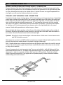
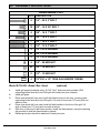
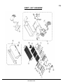
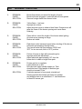
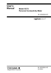
111 North River Road North Aurora, IL 60542 Phone: (800) 323-5664 Fax: (630) 897-0573 [email protected] Model MOBILE-II Instruction Sheet Mobile LP Gas Fired PORTA-GRILL ASSEMBLY, OPERATING & MAINTENANCE INSTRUCTIONS THIS UNIT HAS BEEN CERTIFIED BY ITS/WARNOCK HERSEY TO MEET ANSI Z83.11, CGA 1.8-1994, AGA REQUIREMENT 13-90 AND CAN/CGA-1.6-M88 FOR OUTDOOR USE ONLY www.belson.com TABLE OF CONTENTS PAGE I SAFETY 1 II GETTING STARTED 2 III SAFETY PRACTICES TO AVOID PERSONAL INJURY 3 IV PROPANE TANK STORAGE, HANDLING AND FILLING 4 V CONNECTING AND DISCONNECTING YOUR TANK 5 VI LEAK CHECK 6 VII LIGHTING INSTRUCTIONS 7 VIII IGNITOR AND BURNER ADJUSTMENTS 8, 9 IX CARE AND MAINTENANCE 10, 11 X ASSEMBLY INSTRUCTIONS (SECTION C) GRILL INSTALLATION 12 XI ASSEMBLY (SECTION C) 13 XII ASSEMBLY INSTRUCTIONS (SECTION A) TRAILER ASSEMBLY 14 XIII ASSEMBLY DIAGRAM 15 XIV TRAILER LIGHT KIT 16 XV ASSEMBLY INSTRUCTIONS (PG-200 BREAD BOX HOOD) 17 XVI PART LIST 18, 19 XVII TROUBLE SHOOTING 20 (SECTION A) XVIII WARRANTY 21 www.belson.com 1 I SAFETY Dear Customer: PLEASE read this manual carefully and follow the recommendations enclosed. This will help assure you of the most enjoyable and trouble-free operation of your new PORTA-GRILL. Keep this manual for future reference. FOR YOUR SAFETY If you smell gas: 1. Shut off gas to the appliance. 2. Extinguish any open flames. 3. Open lid. 4. If odor continues, immediately call your gas supplier. FOR YOUR SAFETY Do NOT store or use gasoline or other flammable vapors and liquids in the vicinity of this or any other appliance. Do NOT store any flammable materials in any cabinets beneath the grill burner box or in the vicinity of your grill. WARNING! Improper assembly, adjustment, alteration, service or maintenance can cause property damage, injury, or death. It is your responsibility to assemble, install, leak check, operate and care for your PORTA-GRILL. Read this manual thoroughly before assembling or using this equipment. This manual is based on information available when the manual was printed. Continued improvements in design could cause changes in the grill that may or may not be included herein. Please call customer service 1-800-323-5664 If you have any questions concerning assembly, installation or operation of your grill. PLEASE RETAIN THIS MANUAL FOR FUTURE REFERENCE. www.belson.com 2 II GETTING STARTED PICKING A LOCATION: Your PORTA-GRILL is manufactured for use outdoors only! Any grill, charcoal or gas, produces carbon monoxide while in operation and this gas should not be allowed to accumulate in a confined area. Never operate the grill inside your home, garage, recreational vehicle or any enclosed area. The installation must conform with local codes, or in the absence of local codes, with the National Fuel Gas Code, ANSI Z233.1, National Gas Installation Code, CAN/CGA-B149.1, or the Propane Installation Code, CAN/CGA-B149.2 as applicable. When locating your grill, choose a safe outdoor location away from flammable or combustible surfaces. Locate your grill a minimum of 30 inches from any combustible surface above, behind or to the sides. Never operate your grill on a combustible surface. The PORTA-GRILL is intended for mobile, non-permanent installation only. CAUTION: Never operate your grill under overhangs or awnings. When possible, adjust your grill’s position to reduce the likelihood of wind blowing directly onto it. As your grill uses gas, it requires air to burn with it. Do not locate your grill in such a manner or otherwise obstruct the flow of combustion and ventilation air around the grill. WARNING: For your safety, do not store or use gasoline or other flammable vapors and liquids in the vicinity of this unit or any other appliance. Failure to follow this warning could lead to a fire, explosion and bodily harm. It is important for the proper operation of the grill that it be located on a level surface and out of traffic paths. Children should not be left alone or unattended in an area where the grill is being used. Never allow them to sit, stand or play on or around the grill at any time. The grill surfaces become very hot during use. Use hot pads or oven mitts to protect hands and arms. For personal safety, wear proper apparel. Loose fitting garments or sleeves should never be worn while cooking. Some synthetic fabrics are highly flammable and should not be worn while cooking. PORTA GRILL unit is permissible for indoor storage, only if the L.P. gas cylinder is totally removed from the unit. (See Section V "CONNECTING & DISCONNECTING YOUR TANK" at Pg. 5, and Section VI "LEAK CHECK" at Pg. 6). When the unit is not in use, the supply L.P. gas cylinder valve must be turned off and all control valves on the instrument panel must be turned to the 'OFF' position. The regulator and hose assembly equipped with the unit must be used at all times. Replacement of such assembly must be supplied by BELSON OUTDOORS, INC. www.belson.com 3 III SAFETY PRACTICES TO AVOID PERSONAL INJURY -Don'tsDON’T move your grill while it is in operation or still hot. DON'T use an open flame when testing for gas leaks. DON'T use charcoal briquettes, wood chips or any flammable material on top or in place of lava rock. DON'T store any flammable materials beneath the firebox or in the vicinity of your grill. DON'T use the grill for cooking excessively fatty meats or products which promote flare-ups. DON'T use natural gas in a unit designated for liquid propane. DON'T operate this unit in a building, garage, or any other enclosed area. DON'T operate your grill under overhangs or awnings. DON'T obstruct the flow of combustion and ventilation air into or out of this unit. DON'T use in high wind conditions; high winds may adversely affect burner performances. DON'T use vertical tanks. -Do'sDO store your grill indoors or covered, be sure to close the tank valve, disconnect the hose from the tank, remove the tank from the grill and store the L.P. tank outdoors. DO use a leak proof approved sealing compound on all joints when connecting or replacing any gas fittings. DO fully open the grill hood before lighting your grill. DO remove the control knobs and store them indoors for child safety. DO obtain safety instructions from your local gas supplier, and post in a prominent location near the area of operation.These instructions are to be followed in the event of a gas leak. DO operate your unit outdoors. DO operate this unit in a well-ventilated area. DO position your portable grill away from direct wind. DO inspect flexible gas hose prior to each use. If it is evident that there is excessive abrasion or wear, or the hose is cut, it must be replaced prior to the unit being put into operation. DO use only 40# horizontal propane cylinders (12” diameter, 29” length) supplied with unit. Any other cylinder used must be of identical type and must be constructed and marked in accordance with the specifications for LP gas cylinders of the US. Department of Transportation (DOT). DO properly store propane cylinders outdoors in a well ventilated area out of reach of children. Disconnected cylinders must have threaded valve plugs tightly installed and must not be stored in a building, garage, or any other enclosed area. Propane gas is highly flammable! DO lock both casters when operating the grill unit. DO handle, use, store and transport LP gas cylinders in accordance with NFPA 58. www.belson.com 4 IV PROPANE TANK STORAGE, HANDLING AND FILLING Propane gas should be handled and stored with care. We suggest asking your propane gas dealer, when having your tank filled, for a short course in handling, care, and storage of propane gas tanks.Most dealers will be glad to instruct you on how to store and handle your tank. WHERE TO STORE The best place to store a liquid propane tank is in a shady or protected spot outdoors, behind your home or garage, but where it is out of the reach of children. Don't store the tanks - whether full or empty- inside your home or inside the living area of a recreational vehicle. Liquid propane tanks shouldn’t be stored inside a building, your garage, basement or workshop and any other enclosed area. HANDLING AND FILLING All new tanks are filled with air, not LP gas. Air must be purged before the tank is filled. The LP gas cylinder must be constructed and marked in accordance with the specifications for LP gas cylinders of the US. Department of Transportation. Transport tanks in a horizontal position in a secure manner with valves tightly closed. Do not transport tank in the passenger compartment of a car or truck. Stabilize and secure the cylinder in the trunk. Also do not expose the tank to any source of excessive heat. The LP fuel tank should be filled by weight (tank and fuel together not to exceed 70 lbs) to an 80% maximum capacity and never more! You are trying to burn the vapor part of the fuel, not the liquid itself. Never allow your tank to be over-filled. Be sure your LP gas dealer checks the tank with a soapy solution for leaks after filling. A dented or rusty LP tank may be hazardous and should be checked by your LP supplier. Never use a cylinder with a damaged valve and never paint an LP cylinder a dark color for this may cause the cylinder to overheat. CAUTION: Propane is highly flammable! Handle, use, store and transport LP gas cylinders in accordance with NFPA 58. Obtain instructions from your local gas supplier. Use only 40# horizontal Propane cylinder (12" diameter and 29" length), which is supplied with the unit. www.belson.com 5 V CONNECTING AND DISCONNECTING YOUR TANK CONNECTING TANK Mount the L.P. tank to the support bracket with (4) 3/8”-16 x 3/4” hex head bolts. The Belson fuel tank will only draw vapor fumes while lying in the horizontal position as shown on the drawing. Never attempt to use the Belson LP fuel tank in the vertical position or outside of its support hoops. Connect regulator to tank. Be sure arrow on regulator is in direction of gas flow. Connect one end of flexible gas hose to regulator and the swivel end to the manifold assembly. Carefully tighten all fittings. The regulator supplied with your liquid propane gas grill is set for 11” wc and is for use with propane gas only. This regulator and the factory supplied hose assembly must be used when operating your grill. If replacement of the hose and / or regulator becomes necessary, factory specified parts are required. IMPORTANT! Red arrow at top front of the tank and tank valve handle must point up! If frosting occurs on the regulator, the LP tank is not properly mounted or the tank is over filled. (See Section IV "PROPANE TANK HANDLING AND FILLING" Pg. 4) DISCONNECTING TANK Slowly close the liquid propane tank valve and allow burners to burn all gas from the manifold system. Turn burner control knobs to 'OFF' position. Make sure no open flames are present, and allow unit to cool. Disconnect the regulator and insert the safety plug into the tank. Follow all warnings pertaining to storage of propane tanks. (See Section IV "PROPANE TANK STORAGE, HANDLING AND FILLING" Pg. 4) www.belson.com 6 VI LEAK CHECK BEFORE LIGHTING YOUR GRILL: Turn your L.P. gas supply on and test all fittings for leaks, before attempting to light grill, be certain all control valves are in the 'OFF' position. Slowly turn the gas supply on (leaving control valves in the 'OFF' position) and check all connections with a solution of 50% liquid soap, 50% water. Solution can be sprayed on with a spray bottle or painted on all connections with a brush. Soap bubbles will appear where a leak is present. If a leak is present, immediately turn off gas supply, tighten fittings and try again. Check for leaks at least each time you refill the tank and each time you relocate your grill to a new location. WARNING: Do not smoke while leak testing. Never leak test with an open flame. Do not use the PORTA-GRILL until all connections have been checked and do not leak. www.belson.com 7 VII LIGHTING INSTRUCTIONS IMPORTANT: Before each use of your grill, inspect the gas hose prior to turning the gas 'ON' If there is evidence of cuts, wear, or abrasion, it must be replaced prior to use. Contact Customer Service 1-800-323-5664 for replacement parts. Do not use the unit if the odor of gas is present. Keep your face and body as far away from the grill as possible when lighting. STEP 1: Open the hood. Do not stand with your head over the grill when lighting burners. STEP 2: Check all burner control knobs and main gas supply valves are at 'OFF' position. STEP 3: Slowly open the fuel tank to full, by turning to the left (counter-clockwise). STEP 4: Open one burner valve at a time to 'HI' by pushing-in and then turning the control knob to the left (counter-clockwise) about 90 degrees until the 'HI' marking is pointing upwards. STEP 5:Wait 3 to 5 seconds for gas to fully reach for ignition. STEP 6: Depress (push) red ignitor button. You’ll hear a snapping sound. At the same time a spark will be provided at the front of the burner. It may be necessary to press the button 3 to 6 times until the burner is lit. STEP 7: Repeat STEP 4 through STEP 6 for each burner. After the burners are lit, if one burner goes out, the burner will cross-light automatically. IF THE BURNER FAILS TO LIGHT Immediately turn control knobs to 'OFF' to prevent gas buildup. Wait 5 minutes before trying to relight by ignitor. If the burner will not light after several attempts (See Section XVII "TROUBLE SHOOTING" on Pg. 20). TIP: Operate all burners on high for 5 minutes with hood open or until the lava rock becomes hot. Once the lava rock become hot, then turn the burners down to a lower setting and allow the radiant heat of the rock to provide the heat for cooking. SHUTTING DOWN UNIT Close the liquid propane tank valve and allow burners to burn all gas from the manifold system. Turn burner control knobs to 'OFF' position. Make sure no open flames are present, allow unit to cool. Disconnect the regulator and insert the safety plug back to the tank. Follow all warnings pertaining to storage of propane tanks. (See Section IV "PROPANE TANK STORAGE, HANDLING AND FILLING" Pg. 4). www.belson.com 8 VIII IGNITOR AND BURNER ADJUSTMENTS IGNITOR/ELECTRODE ADJUSTMENT The electrode inside the fire box is fixed and checked at the factory for optimum spark. The tip is 1/8” from the inside surface of the burner tube. In the event that the ceramic insulator should crack and need replacement, it is easily removed by loosening the mounting screw. If burner will not light, slide the lava rock at the control panel end to one side and visually inspect the spark produced when the red ignitor button is depressed. Adjust the probe as necessary for best spark. Distance between probe end and the burner should be set at 1/8”. CAUTION: Both LP tank and control knobs must be at 'OFF' position when testing and adjusting the electrode spark. VALVE CONNECTION At the end of each valve there is a tiny gas opening known as an orifice. Gas exits the orifice and enters an air mixer where it mixes with air. The proper mixture of gas and air produces a clean blue flame with slight yellow tips at the burner. The valve flange should be flat against the air mixer as pictured below. Failure to insure this connection may cause fire and result in serious damage to your grill. www.belson.com 9 FLAME ADJUSTMENT Each grill burner is tested and adjusted at the factory prior to shipment; however, variations in the local gas supply or a conversion from one gas to another may make it necessary to adjust the burners. Flames should be blue and stable with no yellow tips, excessive noise or lifting. If any of these conditions exist, check if the air shutter or burner ports are blocked by dirt, debris, spider webs, etc. To adjust gas to air mixture, find screw at end of air mixer where it meets valve. Loosen screw and rotate air shutter to desired mixture. YELLOW FLAME indicates insufficient air. Turn the air shutter counter-clockwise to allow more air to the burner. NOISY AND LIFTED FLAME indicates too much air. Turn the air shutter clockwise. Burner Flame Height: FLARE-UPS When you cook fatty foods over an open flame, you can expect flare-ups. Natural juices falling on the hot lava rock results in flame and smoke that give foods that delicious outdoor flavor and appearance. Expect and encourage a MODERATE amount of flare-up. Excessive flare-ups occur when cooking extra fatty foods, or if cooking temperatures are too high. TO CONTROL FLARE-UPS: TIP 1. Turn your control knobs to a lower setting. TIP 2. Move the meat to another part of the grill that may be at a lower heat setting or OFF. TIP 3. Cook with the lid open to reduce heat inside of grill. TIP 4. EXCESSIVE FLARE-UP:Immediately turn the setting to 'LO' or 'OFF' position, or spray the flame with water. www.belson.com 10 IX CARE AND MAINTENANCE Caution: Avoid steam burns by not using a wet sponge or cloth to clean the grill while it is hot. Some cleaners produce noxious fumes or can ignite if applied to a hot surface. Be sure all grill controls are turned off and the grill is cool before using any type of aerosol cleaner on or around the grill. The chemical that produces the spraying action could, in the presence of heat, ignite or cause metal parts to corrode. CLEANING SOLUTION: WARM WATER AND LIQUID DETERGENT CLEANING THE FIREBOX INTERIOR: Clean when the lava rocks, grate, burners and grill are removed from the firebox. Clean out any ash or deposits which may have settled in the firebox using warm cleaning solution and a soft cloth. If a hose is used to clean the firebox, elevate the end opposite the control panel to drain water from burners. Allow to dry before replacing all parts. GRILL RACK: Use a brass wire brush to remove cooked on food and cleaning solution to clean the grate. Spray a non-stick vegetable oil on grill just before cooking to prevent food from sticking to the surface. WARMING RACK: The cleaning of the chrome warming rack can be accomplished by using the cleaning solution and wiping. For stubborn particles use a brass wire brush. LAVA ROCK: It is not necessary to remove the lava rock for cleaning. They burn themselves clean during the next cooking operation. Periodically the rocks need to be turned over for a thorough cleaning. How often you use the grill and the amount and type of food cooked will determine when it is necessary to clean the lava rock. If grease can be seen on the top of the rocks or if you get a lot of flare-up during cooking, the rocks need to be turned over and heated on 'HIGH' for 30 minutes; longer for heavy soil. The PORTA-GRILL is designed for a single layer of lava rock to be spread evenly over the grill grate above the burners. Do not use more than a single layer to avoid blocking off the air for the grill burners to vent. TIP: Excessive water to control flare-ups will cause lava rock to fracture. To help prevent flare-ups, trim off as much fat as possible. www.belson.com 11 SPIDERS AND INSECTS: The burner venturi area is narrow, dark and protected making the burners extremely attractive to spiders. A nesting spider is capable of spinning a web overnight that could block gas and air flow. This is a very dangerous condition which can cause a fire to occur behind the valve panel, thereby damaging the grill and making it unsafe to operate. You should inspect the burners at least once a year or immediately if any of the following conditions occur: 1. The smell of gas in conjunction with the burner flames appearing yellow. 2. The grill does not heat to high temperatures or heats unevenly. 3. The burners make popping noises. If there is evidence of spiders, immediately turn gas off and try to use a small brush to eliminate the spider webs. If there are webs blocking the air mixer, insert a bottle brush into the end of the burner, twist and pull the webs out. CAUTION: Never, under any circumstances, use a pesticide near your grill to eliminate spiders or other insects, as this could be extremely hazardous. CLEANING THE BURNERS/AIR MIXER: Remove the burner/air mixer assembly, cover the valve orifices with a small piece of aluminum foil to keep out dirt. Clean all burner's port openings, sides and bottom with a stiff wire brush. Any clogged flame holes may be opened using a thin wire. Use a bottle brush, pipe cleaner or long flexible wire to clean out the air mixer. Be extremely careful not to enlarge the hole. TIP: Shine a flashlight through the openings to ensure there is no blockage. CLEAN UNIT THOROUGHLY AFTER EACH USE! www.belson.com 12 X ASSEMBLY INSTRUCTIONS PORTA-GRILL PG-2460-II TRAILER ADAPTER (SECTION C) GRILL INSTALLATION 1. Attach L.P. cylinder mounting plate to trailer adapter box and tongue. Using (2) each 3/8"16x3/4" and (1) each 3/8"-16x3" bolt and nuts provided. 2. Attach aluminum heat shields to adapter box using (2) each 3/8"-16x2" bolts, 1/2" spacers and nuts provided. Note: Spacers go in between aluminum panel and adapter box. 3. Remove cylinder from carton. Place filled cylinder on mounting plate. Note: Under side of trailer has a 3/8" black pipe welded to it. Valve end of cylinder should be closest to the pipe. 4. Attach L.P. cylinder to mounting plate using (4) each 3/8"-16x3/4" bolts and nuts provided. Note: Re-positioning mounting pads of cylinder may be necessary to install cylinder. 5. Attach brass regulator assembly to propane tank. (Note: Left hand thread). Connection between regulator and 3/8" black pipe (under trailer) is made with the 24" flex hose attaching flex hose to the regulator first, then to the black pipe. Use plumbers pipe compound on the connection between the hose and the black pipe. 6. Place PG-2460-PC firebox into adapter box. Note: Instrument panel of firebox is rear of trailer assembly. 7. Attach grill supports onto firebox using (4) 3/8"-16x1" bolts and nuts provided. Note: Front grill support bolts go through adapter box. Hood pins should be outward. 8. Check ignitors for spark by depressing corresponding button for each burner. If no spark is present, check gap between electrode and burner. It should be at about 1/8" gap. Also, check connection at ignitor button. 9. Place lava rock grates on flat surface (cross-brace rods on the top side). Dump lava rock on grates and spread evenly. Note: This is done to prevent smaller pieces from clogging burners. 10. Install lava rock grates. 11. Install nickel chrome plated grill. Note: If PG-200 hood is being used, assemble at this time. See attached instructions. 12. Attach 36" rubber L.P. hose to 3/8" elbow on underside of manifold. Attach other end to the 3/8" black pipe on underside of trailer. Use plumbers pipe compound on connections. 13. With all 4 burners valves in the 'OFF' position, open LP cylinder valve. Fully check all connections for leaks using a soapy water mixture. If no leaks are present, proceed to Step 14. 14. Open one valve fully 1/4 turn counter-clockwise to 'HI' setting. Depress ignitor button to ignite burner. Light remaining 3 burners as needed. 15. Check all bolted connections periodically for tightness. 16. Check all connections periodically for leaks and tightness. www.belson.com 13 XI ASSEMBLY DIAGRAM PG-2460-II TRAILER ADAPTER (SECTION C) GRILL INSTALLATION www.belson.com 14 XII ASSEMBLY INSTRUCTIONS PG-2460-AI, ALL TRAILER ADAPTER (SECTION A) TRAILER ASSEMBLY 1. Lay trailer frame on flat surface, with axle mounting brackets upward. 2. Attach axle assembly to frame as shown in Fig. 1A. Using bolts, nuts and spacers provided. It may be necessary to tap the springs into place using a hammer. 3. Attach ball coupler to tongue assembly using (2) each 3/8"-16x3" bolts, lock washers and nuts provided as shown in Fig. 2A. 4. Attach tongue assembly to trailer frame using (2) each 1/2"-13x3" bolts, lock washers and nuts provided as shown in Fig. 2A. 5. Mount tire and wheel assembly on axle hubs using lug bolts provided. 6. Turn trailer assembly over on wheels. 7. Attach tongue jack with retaining ring as shown in Fig. 3A. 8. Attach tail light brackets to trailer frame using (4) each 1/4"-20x3" bolts, As shown in Fig. 4A. 9. Mount tail lights on brackets using nuts and lock washers provided. 10. Attach adapter box to trailer frame using (4) each 3/8"-16x3" bolts, lock washers and nuts provided. Note: Fender mounting holes are closest to tail lights. 11. Attach fenders to adapter box using (4) each 3/8"-16x3/4" bolts, lock washers and nuts provided. www.belson.com 15 XIII ASSEMBLY DIAGRAM PG-2460-AI, ALL TRAILER ADAPTER (SECTION A) TRAILER ASSEBMLY 16 www.belson.com XIV TRAILER LIGHT KIT WIRING INSTRUCTIONS (SECTION B) VEHICLE CONNECTION Connect the wire of the short trunk connector to the vehicle wiring. Connect the brown wire to the tail light wire, the yellow wire to the left-hand stop and turn the green wire to the right-hand stop and turn wire. Attach the white wire to the vehicle frame. If vehicle has rear turn signals separated from stop lights, you will need an Anderson electronic converter. TRAILER LIGHT MOUNTING AND CONNECTION Feed wires through tongue, leaving approx. 18" of wire hanging out of tongue as shown. Using black plastic tape as shown mount each half of the harness down each side of the trailer, with yellow and brown wires down left side and green and brown wires down right side. Connect yellow and brown wires to left-hand light by stripping harness ends 1/2" and inserting yellow wire into hole marked 'Stop and Turn (yellow)'. Insert brown wire into hole marked 'Tail (brown)'. (Extra holes are spares for auxiliary use). Connect green and brown harness ends to the right-hand light in the same manner. Attach white ground wire to trailer tongue or frame. Mount the light with license window on the left rear of the trailer with side marker to the outside of the trailer. Mount the light without license window on the right rear of the trailer with side marker to the outside. Mount the license bracket with the left-hand light. Optional: Mount the front side marker lights in the area shown. Attach wire to brown harness wire with 3M Scotchlok connector. After lamps are mounted, use 3M Scotchlok connectors to connect all three leads together and then plug into the extra hole marked brown in the back of tail light (either side). Note: Smaller holes above or below circuit holes on all lights are relief holes to be used for removal of wires. By inserting nail or paper-clip into these small holes the strain on the wires can be relived so they can be removed. Connect harness plug to trunk connector plug. Turn on car headlights - both tail lights and all four side markers should come on. The bright stop lights should come on only when the brake pedal is depressed, or when turn signal is activated. (Key must be in 'ON' position). If lights do not light, check all ground connections, If turn signals do not operate properly, check connectors between vehicle wiring and trunk connector. 17 www.belson.com XV ASSEMBLY INSTRUCTIONS HARDWARE LIST QTY DESCRIPTION 4 1/4" - 20 X 3" BOLT 10 3/8" - 16 X 3/4" BOLT 4 3/8" - 16 X 1" BOLT 2 3/8" - 16 X 2" BOLT 7 3/8" - 16 X 3" BOLT 2 1/2" - 13 X 3" BOLT 4 1/4" LOCK WASHER 23 3/8" LOCK WASHER 2 1/2" LOCK WASHER 4 1/4" - 20 HEX NUT 23 3/8" - 16 HEX NUT 2 1/2" - 13 HEX NUT 4 1/2"O.D. x 1/2" 15GA GALVANIZED TUBING Model # PG-200 - Bread Box Hood 1. 2. 3. 4. 5. 6. (optional) Install grill support brackets using (4) 3/8"-16x1" bolts and nuts provided. (Grill supporting hooks face the front of the grill with hood pivot pins outward) Install grill grate. Place inner hood half over rear of grill with firebox hooks to the rear, (cooking grate supporting hooks face the front of the grill). Lift ends of hood over 1/2” pivot pins one side at a time. Place outer hood half over inner hood half with handles to the front of the grill. Lift ends of hood over 1/2” pivot pins one side at a time. With front of the hood in half open position, install the thermometer, using the retaining clip provided to hold the thermometer in placed. Retaining hair pins should be attached to hood pivot pins. www.belson.com 18 XVI PART LIST MOBILE-II PART LIST ITEM NUMBER PART NUMBER QTY/FIX DESCRIPTION 1 PG-II-FB 1 FIREBOX 2 PG-INST2 1 INSTRUMENT PANEL 3 PI-BNRBRKT2 1 BURNER SUPPORT BRACKETS 4 PI-PGIIBNR 4 BURNER TUBES – STAINLESS STEEL 5 PI-GRLSPT 2 GRILL GRATE SUPPORTS 6 PG-IILRG 3 LAVA ROCK GRATES 7 PG-2460G 1 NICKEL PLATED COOKING GRATE 8 PG-200 1 BREAD-BOX HOOD 9 PI-II-HS 1 HEAT SHIELDS (SET OF 2) 10 PI-40HB 1 LIQUID PROPANE TANK(HORIZONTAL) 11 PI-260-00 1 REGULATOR 12 PI-GH25375 1 26 INCH PROPANE HOSE 13 HD-HP0375 2 HAIR PIN 14 PI-21IGN 4 IGNITOR (RED PUSH BUTTON) 15 PI-7ELECT 4 IGNITOR CABLE WITH CERAMIC INS. 16 PI-5619 4 ON / OFF GAS CONTROL KNOB 17 PG-MANFB 1 MANIFOLD 18 BV-L777ESR 4 GAS VALVE 19 PI-100CTM 4 AIR MIXER 20 PI-LAVA 1 LAVA ROCK (50 LBS.) 21 PG-2460AII 1 TRAILER & ADAPTER 22 GH-3753637 1 36 INCH PROPANE HOSE 23 PB-375STL1 1 ELBOW 24 PI-5972A 1 THERMOMETER WITH CLIP www.belson.com 19 PART LIST DIAGRAM www.belson.com 20 XVII TROUBLE SHOOTING 1. PROBLEM: CAUSE: SOLUTION: Burner flame does not extend full length of burner. Burner holes are plugged or restricted with dirt and grease. Remove foreign matter from burner holes. 2. PROBLEM: CAUSE: SOLUTION: Yellow flame -- low heat. Improper air mixture. Adjust air mixer cover to obtain a blue flame. Excessive air will raise the flame off the burner opening and cause flame fluttering. 3. PROBLEM: CAUSE: SOLUTION: Flame will not ,travel the length of the burner when lighting. Air mixer cover opening too large. Reduce air intake. 4. PROBLEM: CAUSE: SOLUTION: Flash back under instrument panel when shutting off the burner. Unburned gas escaping through mixer. Turn burner valve half way between 'HIGH' and 'OFF' for ten seconds, then to 'OFF' position. 5. PROBLEM: CAUSE: SOLUTION: Failure of burner to light with automatic ignitor. Improper electrode adjustment. Adjust electrode approximately 1/8" from the burner hole to obtain a bright blue spark. 6. PROBLEM: CAUSE: SOLUTION: Frozen gas line or regulator. Liquid petroleum in line. Re-orient tank valve handle straight up. Tank should be level. Filled weight of tank and gas should not exceed 70 lbs. If cylinder appears to be properly oriented and freezing persists disconnect gas line from cylinder and bring the tank to a authorized L.P. tank distributor to bleed off excess gas. SOLUTION: www.belson.com 21 XVIII WARRANTY Belson Policies We at Belson take extreme care to ensure that your shipment arrives in acceptable condition. When your shipment arrives, the carrier will provide you with a delivery receipt. It is vital that you count the number of pieces being delivered and inspect for damages prior to signing the this document. No claims for damaged or missing merchandise can be made unless it is recorded on this delivery receipt. Claims for hidden damage must be reported within 15 calendar days of receipt of delivery. Should you have any questions or encounter any difficulty, please call our Customer Service Department at 1-800-323-5664. Return Merchandise Policy Prior written approval and instructions must be issued by our Customer Service Department before any merchandise can be returned. All merchandise must be properly packed and returned in its original packaging, freight Prepaid. No Collect shipments can be accepted. Merchandise returned for reasons other than damage or defect may be subject to a 20% re-stocking fee. Warranty Every Belson product is warranted against defects in material and workmanship for 1 full year from the date of shipment. Misuse, neglect or alteration of product is not covered under this warranty. www.belson.com