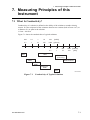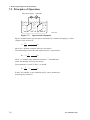
1
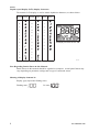
User’s
Manual
Model SC72
Personal Conductivity Meter
IM 12D03D02-01E
IM 12D03D02-01E
1st Edition
Preface
Preface
Before using the Model SC72 Personal Conductivity Meter, read this manual thoroughly.
For safe use of this meter, the meter and the instruction manual include the following
symbol marks.
WARNING :
CAUTION
:
Indicates that serious injury may result, if users fail to follow
instruction manual procedures.
Indicates that minor injury to personnel, or serious damage to
the product, may result if users fail to follow procedures in the
instruction manual.
WARNING
Do NOT use this instrument where there is a danger of electrical shock.
Do NOT touch any part of the electrode immediately after measuring very hot liquids —
otherwise, you may get burnt.
CAUTION
If the meter will not be used for an extended period of time, be sure to remove the
battery. Otherwise battery leakage may occur, and may cause damage to the meter or
cause erroneous meter operation.
The contents of this manual are subject to change without prior notice.
Yokogawa Electric Corporation assumes no liability for damage, defects, or loss of the
product caused by any of the following:
User error;
Inappropriate or out-of-specifications use of the product;
Use in an unsuitable environment;
Repair or modification of this or related products by persons other than Yokogawaauthorized engineers.
IM 12D03D02-01E
1st Edition: Aug. 2004 (YK)
All Rights Reserved, Copyright © 2004, Yokogawa Electric Corporation
1
Preface
Liquid crystal display (LCD) display characters
The numeric LCD display is used to mimic alphabetic characters, as shown below:
Alphabet
Display
Alphabet
Display
Numerals
A
N
0
B
O
1
C
P
2
D
Q
3
E
R
4
F
S
5
G
T
6
H
U
7
I
V
8
9
J
W
K
X
L
Y
M
Z
Display
All display elements shown ON
F00.EPS
Note Regarding Panels Shown in this Manual:
Panels shown in this manual should be regarded as examples. Actual panel format may
vary depending on parameter settings and on type of connected sensor.
Showing all display elements lit
Display (gray represents flashing state)
Flashing state:
2
Lit state:
IM 12D03D02-01E
Preface
Warranty and Service
Yokogawa products and parts are guaranteed to be free from defects in workmanship and
materials under normal use and service for a period of (typically) 12 months from the
date of shipment from the manufacturer.
Individual sales units may offer different warranty periods, so the original purchase order
should be consulted for the conditions of sale. Damage caused by normal wear and tear,
inadequate maintenance, corrosion, or due to chemical processes, is excluded from this
warranty coverage.
In the event of a warranty claim, any items that are considered to be defective should be
sent (freight paid) for repair or replacement (at Yokogawa discretion) to the service
department of the relevant sales unit. The following information must be included in a
letter accompanying the returned items:
Model code and serial number
Copy of original purchase order showing the date
Length of time used, and the measuring environment
Fault symptoms, and circumstances of failure
Statement whether service under warranty or out-of-warranty service is requested
Complete shipping and billing instructions for return of goods, plus the name and
phone number of a contact person who can be reached for further information
Goods that have been in contact with process fluids must be decontaminated / disinfected
before shipment, and a statement to this effect should be included. Safety data sheets for
all process components that the goods have exposed to should also be included.
IM 12D03D02-01E
3
Contents
CONTENTS
Preface ...................................................................................................................... 1-1
1. Outline ................................................................................................................. 1-1
1.1
1.2
1.3
1.4
1.5
1.6
1.7
1.8
Features .........................................................................................................................
Personal Conductivity Meter Specifications ..................................................................
When You Receive This Conductivity Meter .................................................................
Contents of Model SC72 Personal Conductivity Meter Package .................................
Component Names and Functions ................................................................................
Sensor Part Names and Functions ...............................................................................
Options (Available Separately) ......................................................................................
Spare Parts ....................................................................................................................
1-1
1-2
1-3
1-4
1-5
1-6
1-8
1-8
2. Preparation .......................................................................................................... 2-1
2.1
2.2
2.3
2.4
2.5
2.6
Installing the Batteries ...................................................................................................
Connecting Sensor Cable ..............................................................................................
Setting Date and Time ...................................................................................................
Setting Temperature Unit ..............................................................................................
Setting Cell Constant .....................................................................................................
Setting Temperature Compensation Coefficient ...........................................................
2-1
2-2
2-3
2-4
2-4
2-6
3. Measurement ...................................................................................................... 3-1
3.1
3.2
3.3
3.4
Precautions ....................................................................................................................
Measurement Procedures .............................................................................................
Measurement Panel .......................................................................................................
Saving Measured Value ................................................................................................
3-1
3-2
3-3
3-3
4. Keyswitch Functions .......................................................................................... 4-1
4.1 Names and Functions of Keys ...................................................................................... 4-2
4.2 Liquid Crystal Display and Display Items ...................................................................... 4-4
4.3 Function Modes ............................................................................................................. 4-5
5. Handling of the SC72 Personal Conductivity Meter ........................................ 5-1
5.1
5.2
5.3
5.4
5.5
Tips to Maintain Meter Performance .............................................................................
Washing the Electrode ..................................................................................................
Cleaning and Drying Connector ....................................................................................
Calibration with Standard Solution ................................................................................
Storage and Maintenance .............................................................................................
5-1
5-2
5-3
5-4
5-7
6. Troubleshooting ................................................................................................. 6-1
6.1
6.2
6.3
6.4
Causes of Abnormal Conductivity Display ....................................................................
Error Messages and Corrective Action .........................................................................
Causes of Abnormal Measured Value ..........................................................................
Other conditions .............................................................................................................
6-1
6-2
6-4
6-4
7. Measuring Principles of this Instrument .......................................................... 7-1
7.1
7.2
7.3
7.4
What Is Conductivity? ....................................................................................................
Principles of Operation ..................................................................................................
Temperature Compensation and Finding Temperature Compensation Coefficient .....
Wetted Part Materials of Sensors .................................................................................
7-1
7-2
7-3
7-4
Appendix ..................................................................................................................... 1
Revision Record .......................................................................................................... i
4
IM 12D03D02-01E
1. Outline
1. Outline
The Model SC72 Personal Conductivity Meter is an accurate, portable, easy-to-use
conductivity meter. It includes not only self-diagnostic functions, to help ensure validity
of readings, but also data storage functions to allow users to check past data. The meter
is of waterproof construction so that it can safely be used outdoors on a rainy day, and
can also withstand being accidentally dropped into water.
1.1 Features
Water resistant case
When this meter is used with its dedicated sensor, it meets the requirements of class IP67
“Degree of Protection to be Provided by Enclosures” in IEC 60529.
Wide measurement range, and convenient “Auto Range” function
Sensors are available to cover measurement ranges between 0 to 2.000 mS/cm and 0 to 2
S/cm. Auto-range functions automatically set the optimum measurement range, making
measurement easy.
Automatic temperature compensation
Automatic temperature compensation functions are provided for liquid measurement.
Conductivity referenced to 258C can be obtained in solutions with temperature
coefficients between 0.00 and 9.99%/8C. The temperature coefficients for NaCl solutions
are already stored in the meter.
Calendar and time functions
Internal time functions allow “one-touch checking” of measurement date and time.
Data storage function
Up to 300 conductivities and temperature measurements, and their measurement date and
time, can be saved. This function allows you to check past measurement data.
Automatic power off function
The meter will power off automatically if not operated during a preset time interval.
The time interval can be set in one-minute increments in the range 1 to 120 minutes to
meet your application requirements. This automatic power off function can also be
disabled, but it is wise to leave it enabled to conserve the batteries.
Simple alarm clock function
The meter can issue an alarm signal at a specified time. Even when meter power is
turned off, the internal clock can issue an alarm signal.
Internal self-diagnostic functions display messages when appropriate.
Bright easy-to view large LCD
Displays liquid conductivity, liquid temperature, temperature coefficient, date and time.
IM 12D03D02-01E
1-1
1. Outline
1.2 Personal Conductivity Meter Specifications
Applicable measurement range:
• Sensors for high purity water measurement (cell constant: 0.05 cm-1)
Conductivity:
0 to 2mS/cm, 0 to 20mS/cm, 0 to 200mS/cm, 0 to 40MV•cm
Temperature:
0 to 808C
• For general-purpose sensors (cell constant: 5 cm-1)
Conductivity:
0 to 20mS/cm, 0 to 200mS/cm, 0 to 2mS/cm, 0 to 20mS/cm,
0 to 200mS/cm,
Temperature:
0 to 808C
• For chemical-corrosion-resistant sensors (cell constant: 5 cm-1)
Conductivity:
0 to 20mS/cm, 0 to 200mS/cm, 0 to 2mS/cm, 0 to 20mS/cm,
0 to 200mS/cm
Temperature:
0 to 808C
• Sensors for high-conductivity measurement (cell constant: 50 cm-1)
Conductivity:
0 to 2mS/cm, 0 to 20mS/cm, 0 to 200mS/cm, 0 to 2S/cm
Temperature:
0 to 808C
Resolution: Conductivity:
Temperature:
Least significant digit: 1 digit;
0.18C
Repeatability (Conductivity):
62% (65% for general-purpose sensor on 0 to 200mS/cm measurement range)
Accuracy (Temperature): 60.78C (in the range 0 to 708C)
618C (when exceeding 708C)
Temperature compensation range:
variable 0.00 to 9.99%/8C, also (preset) NaCl solution temperature coefficient
Measurement converted to conductivity at standard temperature of 258C
Measured liquid temperature: 0 to 808C (0 to 508C when the sensor cable is immersed in
water)
Ambient temperature:0 to 508C
Construction:
IEC 60529, IP67 class of protection from environment
Power requirement: Two of size AA batteries (LR6)
Automatic power off interval: May be set in range 1 to 120 minutes
Battery life:
About 200 hours of continuous use, for long-life alkaline battery (life
may vary depending on battery type and ambient conditions)
External dimensions: Approximately 150 (H) x 61 (W) x 42 (D) mm (not including
protruding portions)
Weight:
1-2
Approximately 220 g (including batteries)
IM 12D03D02-01E
1. Outline
1.3 When You Receive This Conductivity Meter
Confirm that all SC72 meter package components (refer to Contents of Model SC72
Personal Conductivity Meter Package in Section 1.4 and sensor models described in Sec.
1.6, “Sensor Part Names and Functions.”) have been received. Carefully inspect the
meter and sensor, referring to Section 1.5, “Component Names and Functions” when
assembling meter and sensor.
Particular attention should be taken:
* Not to twist or force the cable.
* Not to hit or drop the meter.
* Not to get the sensor connector dirty.
IM 12D03D02-01E
1-3
1. Outline
1.4 Contents of Model SC72 Personal Conductivity Meter
Package
Quick Manual
3
User's
Manual
Instrument Card
6
1
5
2
SC72 -
-
4
- AA
7
9
8
10
11
11
SC72 - 11 -
- AA *1
-23
-31
-41
Label
language
-
-J
-E
- AA *1
- AA
SC72 - 31 -
Specification
Personal conductivity meter
Meter only, without sensor
With sensor for high purity water measurement
(cable length: 0.75m)
With general-purpose sensor
(cable length: 0.75m)
With general-purpose sensor (cable length: 3m)
With chemical-resistant sensor
(cable length: 0.75m)
With sensor for high-conductiivity measurement
(cable length: 0.75m)
Japanese
English
-AA Always -AA
Model Suffix code
SC72
Sensors -00
-11
-21
SC72 - 21 SC72 - 23 -
11
11
- AA *1
No.
1
2
3
4
5
6
7
8
9
10
11
SC72 - 41 -
Name
Personal conductivity meter
Two dry batteries
Two instruction manual
Non-slip pads (two)
Hand strap
Instrument card
Sensor for high purity water
measurement
General-purpose sensor
Chemical-resistant sensor
Sensor for high-conductivity
measurement
Sensor cleaner
(five cotton swabs)
*1 The meter model number and cell constants, as well as the sensor model no. (SC72SN-u-AA), are
shown on the nameplate.
1-4
- AA *1
F010401.EPS
IM 12D03D02-01E
1. Outline
1.5 Component Names and Functions
O-ring
Sensor cable connector
Used to connect a dedicated
conductivity sensor to the
personal conductivity meter.
Can attach hand strap here
Display
Displays conductivity,
temperature, and
temperature coefficient
simultaneously.
Battery box cover fixing screw
Key switches
PERSONAL
SC METER
MODEL
SC72
STYLE
S1.0
No.
Instrument name plate
with model number
and serial number
E000001
2004.
F010501.EPS
IM 12D03D02-01E
1-5
1. Outline
1.6 Sensor Part Names and Functions
Four types of sensors are available for use with the Model SC72 Personal Conductivity
Meter:
(1) sensor for high purity water measurement (cell constant 0.05 cm-1),
(2) general-purpose sensor (cell constant 5 cm-1),
(3) chemical-resistant sensor (cell constant 50 cm-1), and
(4) sensor for high-conductivity measurement (cell constant 50 cm-1). Check the model
number and cell constant on the name plate to confirm which type of sensor you
have.
Model number and cell constants display plate example
MODEL SC72SN
CELL
CONST
SUFFIX -11-AA
NO.
000001
Cell constants
STYLE
S1.0
Made in Japan
SC72SN Conductivity sensors for personal conductivity meter
Model Suffix code Specification
Remarks *2
Conductivity sensor for personal conductivity meter
SC72SN
For SC72; for high purity water measurement (cable
-11
length: 0.75m)
For SC82; for high purity water measurement (cable
-19
K9221XB
length: 0.75m) *1
For SC72; for general purpose type (cable length: 0.75m)
-21
For SC72; for general purpose type (cable length: 3m)
-23
1
For SC82; for general purpose type (cable length: 0.75m)* K9221XA
-29
For SC72; for chemical-resistant type (cable length:
-31
0.75m)
For SC82; for chemical-resistant type (cable length:
-39
K9221XC
0.75m) *1
For SC72; for high conductivity measurement (cable
-41
length: 0.75m)
For SC82; for high conductivity measurement (cable
K9221XD
-49
length: 0.75m) *1
-AA Always -AA
*1: Waterproofing is not guaranteed if you use SC82-type conductivity sensor in conjunction
with SC72 meter.
F010601.EPS
*2: Old part number for SC82 conductivity meter.
1-6
IM 12D03D02-01E
1. Outline
Sensor for high purity water measurement
SC72 - 11 -
General-purpose sensor
SC72 - 21 SC72 - 23 -
- AA *1
Model number and
cell constants display plate
- AA
- AA
*1
Model number and
cell constants display plate
(SC72SN-11-AA) *1
(SC72SN-21-AA,*1
SC72SN-23-AA)
Watertight cover
Prevents moisture
from entering
connector and causing
leakage between pins.
Watertight
cover
Sensor
cable
Connector
Connects sensor cable to
conductivity meter
Connector
Sensor cable
Sensor body
Outer electrode
connection
(SUS316
stainless seel)
Sensor grip
Sensor grip
Inner electrode
(Titanium)
Sensor body
Inner electrode
(SUS316
stainless seel)
Plastic body can
withstand temperatures
up to 808C.
Edge electrode
(Titanium)
Outer electrode
(SUS316 stainless seel)
Cover (Plastic)
F010602.EPS
Chemical-resistant sensor
SC72 - 31 -
- AA
Sensor for high-conductivity measurement
*1
SC72 - 41 -
- AA *1
Model number and
cell constants display plate
Model number and
cell constants display plate
(SC72SN-41-AA) *1
(SC72SN-31-AA) *1
Watertight
cover
Watertight
cover
Sensor
cable
Connector
Sensor cable
Connector
Sensor grip
Air vent
Sensor grip
Air vent
Sensor body (glass)
Sensor body (glass)
Inner electrode
(platinum black)
Inner electrode
(platinum black)
*1 SC72SN-u will be described on sensor's name plate for the model number.
IM 12D03D02-01E
F010603.EPS
1-7
1. Outline
1.7 Options (Available Separately)
The following options are available for the Personal Conductivity Meter for your
convenience. When ordering, specify part number shown below.
Standard solution
(Part no.: K9221ZA)
Soft case
(Part no.: B9269KJ)
Sensor stand
(Part no.: K9220XN)
Approx. 280
Unit: mm
0
Appro
0.1mol/l NaCl solution for
calibration (250ml)
.3
rox
x. 140
App
This soft black carrying case holds
conductivity meter and sensor.
This stand holds the sensor when
the conductivity meter is used on a
table. It is made of rustproof
stailess steel.
F010701.EPS
1.8 Spare Parts
O-rings and gaskets are important parts to ensure that the SC72 meter is water resistant.
Replace these parts as required. Refer to Section 5.5, “Storage and Maintenance” for
replacement.
O-ring and gasket set
(Part no.: K9654AY)
Two battery box gaskets
Two sensor connection O-rings
F010801.EPS
1-8
IM 12D03D02-01E
2. Preparation
2. Preparation
2.1 Installing the Batteries
Install the batteries first.
CAUTION
Select a relatively moisture-free location when installing batteries in the meter.
When installing batteries, observe correct polarity (battery orientation).
Failure to do so may damage to the meter.
Remove batteries from the meter if it is to be stored for an extended period of time.
Do not leave dead batteries in the meter. They may leak and cause meter failure or
erratic operation of the meter.
When replacing batteries, replace both batteries at the same time. If only one battery is
replaced, the new battery may discharge into the old battery, which may leak chemicals
and damage the meter.
If the battery box gasket is damaged or dirty then the unit may no longer be waterproof;
replace the gasket in this case.
(1) Loosen the battery box
cover with a coin or the like.
(2) Remove battery cover and
install batteries as shown in
figure.
(3) Check for foreign material
on sealing gasket around
battery box.
(4) Secure tip of battery box
cover in the battery box and
close the cover.
Gasket
(5) Tighten the battery box
cover with a coin or the like.
F020101.EPS
IM 12D03D02-01E
2-1
2. Preparation
2.2 Connecting Sensor Cable
Connect the sensor cable as shown below.
CAUTION
Select a relatively moisture-free location when connecting the sensor cable.
Take care not to wet or dirty the connector when connecting the sensor cable.
Model SC82 sensors can be connected, but these are not guaranteed to be waterproof
when used with this meter.
(2)
(1) Pull the waterproof cover along the
sensor cable away from the
Locknut
connector to expose the locknut.
(2) Connect the connector to the meter
(1)
body*, and tighten the locknut
firmly so that it won't come loose.
* Align sensor connector with sensor
body connector.
Waterproof cover
O-ring
(4)
(3)
(3) Move the waterproof cover towards
the connector until it firmly
contacts the O-ring on the meter
body.
* Align sensor connector with sensor
body connector.
(4) Next turn the cover 90 degrees in the
direction shown in the figure to lock
it.
F020201.eps
Caution:It is recommended that, as far as possible, you leave the sensor connected to the
meter to help ensure that the connector does not get dirty.
2-2
IM 12D03D02-01E
2. Preparation
2.3 Setting Date and Time
After installing the batteries, set the date and time. Note that if the power is turned off
after setting “minutes,” start with the date setting when you turn on the power next time.
If you replace the batteries, the date is not affected, but the time is reset. Reenter the
time.
Caution:If the sensor is not connected then an error will be displayed on the meter.
• Setting method
After installing batteries, press and hold the
POWER
key for at least one second. Then
all display elements turn on and the date setting display automatically appears. Set year,
month, day, hours, and minutes as follows:
Caution:If you stop part way through the date and time setting then the meter will beep
and the date and time will not be updated.
After
POWER
key for at least 1 sec.
pressing
Month setting
Year setting
to set
After
several
seconds
F/ENT
to confirm
to set
Day setting
F/ENT
to confirm
Minute setting
Hour setting (24-hour format)
to set
to set
F/ENT
F/ENT
to confirm
to confirm
to set
After
several
seconds
F/ENT
to confirm
or
F020301.EPS
IM 12D03D02-01E
2-3
2. Preparation
2.4 Setting Temperature Unit
Default temperature units are 8C. To change to 8F, refer to Sec. 4.3 (13) Set temperature
units (tP.U) panel.
2.5 Setting Cell Constant
Even for sensors of the same type, each sensor has its own distinct cell constant. So, set
the proper cell constant as indicated on the sensor cable.
Whenever sensors are replaced, be sure to change the cell constant setting in the meter
accordingly. Cell constants once set are stored in non-volatile memory and are not lost
even when the batteries are replaced.
• Setting cell constants
Press the
F/ENT
key to switch to function mode. Then select the C.C display with the
key and access the cell constant setting display with the
key to set the cell constant, then press the
F/ENT
F/ENT
key. Use the
key to confirm it.
Refer to Sec. 4.3 (4).
2-4
IM 12D03D02-01E
2. Preparation
F/ENT
for Function mode
select C.C
F/ENT for C.C panel
to enter C.C
F/ENT
MEAS
F020501.EPS
You can abort this procedure at any time by pressing
MEAS
to revert to measurement
mode.
IM 12D03D02-01E
2-5
2. Preparation
2.6 Setting Temperature Compensation Coefficient
As described in Section 7.3, liquid conductivity varies with liquid temperature.
Therefore, if concentration is measured by conductivity, the conductivity must be
converted to equivalent conductivity at a certain temperature. This instrument
incorporates standard temperature conversion functions to convert liquid conductivity
measurements to equivalent conductivity at 258C. To display equivalent liquid
conductivity at 258C, set the temperature compensation coefficient as described in this
section.
Temperature coefficient for NaCl solutions is stored in this instrument. If any other
solution is used, set the temperature compensation coefficient manually.
Refer to Sec. 4.3 (2) Temperature compensation setting (t.Co) panel.
2-6
IM 12D03D02-01E
2. Preparation
• Set the temperature compensation coefficient
F/ENT
for Function mode
select t.Co
F/ENT for t.Co panel
For NaCl solutions
Manual setting
select NaCl or
%/8C (%/8F)
F/ENT
Set the temperature
compensation coefficient
with the
keys.
F/ENT
F/ENT
MEAS
MEAS
The temperature coefficient you set is displayed here
IM 12D03D02-01E
F020601.EPS
2-7
2. Preparation
2-8
IM 12D03D02-01E
3. Measurement
3. Measurement
3.1 Precautions
(1) Be sure to check that the cell constant and the temperature coefficient are set
correctly.
(2) Check that the plastic cover (for general-purpose sensor) and outer electrode (for
high purity water measurement) are secure.
(3) Do not use the SC72 meter to measure liquids with temperatures over 808C. (If the
whole sensor including cable is immersed, liquid temperature shall be below
508C.) Do not use the meter to measure extremely corrosive liquids such as
solutions of hydrofluoric acid.
(4) Remove dirt and stains from the meter with soft tissue. If necessary, wipe the
meter case with neutral detergent.
(5) If any problem with the meter arises during measurement, refer to the
Troubleshooting section later in this manual to determine the cause.
(6) After finishing measurement, flush stains on the sensor and measured solutions
with water, and store the meter (refer to Chapter 5, “Handling of the SC72
Personal Conductivity Meter”).
When the meter is used on a table:
The meter is designed as a portable instrument; however, to use it on a table, attach nonslip pads (supplied with the instrument) at top and bottom of the meter to stop it from
moving when the sensor is moved.
Non-slip pads
PERSONAL
SC METER
M O DEL
SC72
STYLE
S1.0
N o. E00000 1
2004.
F0301.EPS
Figure 3.1
IM 12D03D02-01E
Position of non-slip seats
3-1
3. Measurement
3.2 Measurement Procedures
Dipping sensor into liquid
To help avoid errors due to air bubbles around the sensor element (inner electrode),
immerse the sensor into the liquid to be measured so that its air vent is below liquid
level. To dislodge any air bubbles from the inner electrode, dip the sensor into the liquid
and move it up and down two or three times.
Air vent
Measuring liquid level
Cover
Electrode
element
If air bubbles are on this section,
measurement error may occur.
F0302.EPS
Figure 3.2
3-2
Dipping Sensor in Liquid (for general-purpose sensors)
IM 12D03D02-01E
3. Measurement
3.3 Measurement Panel
Immerse the sensor into the liquid to be measured to display the liquid conductivity on
the LCD display.
There are three measurement panel display types: the standard display, calendar, and
clock display.
MEAS
Use the
key to toggle the display type.
Standard display
Calendar display
Clock display
conductivity
MEAS
MEAS
Measuring liquid
temperature
day month year
Temperature
compensation coefficient
hour : minute
MEAS
This display appears when NaCl
solution is specified at temperature
compensation coefficient setting.
F030301.EPS
3.4 Saving Measured Value
The meter offers two ways of storing measured values: HOLD for temporary storage and
non-volatile data storage that retains data even if batteries are removed.
(1) HOLD
If the
HOLD
key is pressed during measurement, the measured values are temporarily
held (display no longer changes).
Press the
HOLD
key or
MEAS
key to return to the measurement mode.
HOLD
HOLD
IM 12D03D02-01E
or
MEAS
F030401.EPS
3-3
3. Measurement
(2) Data storage
If the
F/ENT
DATA
key is pressed during measurement,
mark starts flashing. Press the
key, then currently measured data can be stored in nonvolatile memory. Data
stored are measured conductivity, measured temperature, date and time. Up to 300 data
including individually deleted data can be stored. If you attempt to store more data,
is displayed.
If
is displayed even though the number of data stored is less than 300, perform
“defrag” [refer to Section 4.3 (15), “Defragment storaged data (DFLG) panel”]. By doing
so, you can increase the number of data to be stored.
To check stored past data, refer to 4.3 (1) dAt (display stored measurement value) later
in this manual.
While
is flashing, press the
DATA
key or
MEAS
key to return to measurement
mode without storing data.
DATA
Abort data storage.
While
is flashing, press DATA
or MEAS keys to abort data storage.
Execute data storage.
Press
3-4
F/ENT
key to store data while
is flashing.
F030402.EPS
IM 12D03D02-01E
4. Keyswitch Functions
4. Keyswitch Functions
There are seven membrane keys on the keyboard of the Personal Conductivity meter.
The following key functions are provided.
* Display the conductivity, measured temperature and temperature coefficient.
* Display the conductivity, date and time.
* Hold conductivity and temperature measurements.
* Store conductivity and temperature measured data.
* Other functions such as parameter setting.
When meter is OFF, press for at
least 1 sec. to turn on power.
When meter is ON, press for
about 2 sec. to turn off the power.
Automatic Power OFF function
default: 20 min. inactivity.
If you press this key during
measurement,
mark is
displayed, and present measured
values are held. To return to MEAS
mode, press HOLD or MEAS keys.
If pressed during measurement,
mark flashes.
Press
key to store measured
values in memory.
To abort data storage and return to
MEAS mode, press DATA or MEAS key
again while
mark is flashing.
F/ENT
Auto Power Off
POWER
MEAS
HOLD
F/ENT
DATA
Press to start
measurement mode.
If already in MEAS
mode, it switches the
display panel.
If pressed while in
MEAS mode, switches
to function mode. Also
used to enter set
value.
Change set value.
F040001.EPS
IM 12D03D02-01E
4-1
4. Keyswitch Functions
4.1 Names and Functions of Keys
POWER
: Power ON/OFF key
If nothing is displayed on the LCD, hold down this key for about one second or more to
turn the power on.
If something is displayed on the LCD, pressing and holding this key for about two
seconds turns power off. If no keys are pressed during a certain time interval, power
turns off automatically (refer to “A.oFF,” Set Auto Power Off Interval of Section 4.3
(10)).
HOLD
: HOLD key
Press the
HOLD
key to hold the currently-displayed conductivity and temperature
measurement values (
Press the
and turn
DATA
HOLD
key or
mark turns on).
MEAS
key again to return to measurement mode
mark off.
: Data key
When the meter is in measurement mode, pressing this key causes the
mark to
flash and the currently-displayed conductivity and temperature measurement values to be
temporarily stored. Pressing the
F/ENT
key while the
mark is flashing stores
the data and returns to measurement mode.
To abort data storage, press the
DATA
key or
MEAS
key again; the
mark
turns off and the meter returns to measurement mode.
MEAS
: Measurement key
In measurement mode, pressing this key toggles between different LCD display types
(refer to Section 3.2, “Measurement Procedures”).
If this key is pressed while in any mode other than measurement mode, the instrument
returns to measurement mode. If you want to cancel any operation, pressing this key
returns you to measurement mode.
: Setting change key
Used to change settings.
4-2
IM 12D03D02-01E
4. Keyswitch Functions
F/ENT
: Entry key
In measurement mode, pressing this key switches the meter to function mode (see
Section 4.3, “Function Modes”). This key is also used to confirm set values.
Buzzer (Beep) sound
When a key is pressed, the buzzer beeps. Where the buzzer beeps once, or when it beeps
three times continuously, the meaning is as follows:
(1) When the buzzer beeps once:
This means that key operation was accepted.
(2) When the buzzer beeps three times continuously:
This means that the key operation was not accepted.
To disable the above key entry beep, refer to Sec. 4.3 (11) Set buzzer ON/OFF (bZ.o)
panel.
Note:
the sound volume level of the beep cannot be adjusted by the user.
IM 12D03D02-01E
4-3
4. Keyswitch Functions
4.2 Liquid Crystal Display and Display Items
Displays and their explanations are shown below.
Remaining battery life display
Temp. compensation setting mode
Manual range setting mode
Data save mode
HOLD mode
Calibration with std. solution
Cell constant set mode
F040201.EPS
(1) Remaining battery life display
Remaining battery life is always displayed stepwise. When display is
, battery is
normal. When a flashing
is displayed, battery power is low. Replace the
batteries immediately if the above flashing battery symbol appears. Press
POWER
and
confirm that display turns off, then refer to Sec. 2.1 for battery replacement procedure.
(2) Temperature compensation setting mode
This mark appears when temperature compensation is being set (refer to Temperature
compensation setting (t.Co) panel in Section 4.3 (2))
(3) Manual range setting mode
Normally autoranging is used, and optimum range is selected automatically, but if fixed
(manual) range setting is used then this mark appears (refer to Range selection (rnG)
panel in Section 4.3 (3)).
(4) Data save mode
This mark appears when measured data are stored or when already-stored data are
accessed (see Operation of DATA key in Section 4.1, or Display stored measurement
value in Section 4.3 (1)).
(5) HOLD mode
This mark appears while measured data are being temporarily held (refer to Operation of
HOLD
key in Section 4.1).
(6) Calibration with standard solution
This mode display appears when the calibration with standard solution is conducted
(refer to Calibration with standard solution (CAL) panel in Section 4.3 (5)).
(7) Cell constant set mode
This mode display appears when the sensor cell constants are manually set (refer to Cell
constant setting (C.C) panel in Section 4.3 (4)).
4-4
IM 12D03D02-01E
4. Keyswitch Functions
4.3 Function Modes
Outline
A variety of functions are supported by function mode. Press the
F/ENT
key to switch
from measurement mode to function mode. This mode supports the functions listed in
the table below.
Note:
The last selected and executed item is displayed when you switch to function
mode. Pressing the
keys displays the items listed in Table 4.1 in turn.
Methods of setting items
Use the
the
key to move to the desired item. While the desired item is flashing, press
F/ENT
key to set each item in detail.
To return from the function mode to the measurement mode, press the
Table 4.1
Item
*1
MEAS
key.
Items set in function mode
Default value *2
Details
For detais, refer to:
dAt
Display stored measurement value
no dAta
Item (1)
t.Co
Temperature compensation setting
0.00 %/ 8C
Item (2)
rnG
Range selection
Auto
C.C
Cell constant setting
Item (3)
*3
Standard cell constant Item (4)
CAL
Calibration with standard solution
2
Item (5)
dEL.A
Delete all stored measuring data
2
Item (6)
dAtE
Date setting
2004, January, 1
Item (7)
tIME
Time setting
0 hour 0 minute
Item (8)
ALM
Alarm time setting
oFF
Item (9)
A.oFF
Set Auto Power Off interval
20 min
Item (10)
bZ.o
Set buzzer ON/OFF
on
Item (11)
SC.U
Set measurement unit
S/cm
Item (12)
tP.U
Set temperature unit
8C
Item (13)
VEr
Version number display
2
Item (14)
Defragment storaged data
2
Item (15)
dFLG
*1: Numeric display used to simulate alphabetic character display.
*2: 2: This data is not user-settable
*3: The standard cell constant for the connected sensor is displayed.
IM 12D03D02-01E
T0401.EPS
4-5
4. Keyswitch Functions
Details about how to set each item are provided below.
(1) Display stored measurement value (dAt) panel
Used to display stored measurement values.
mark appears in the top left corner
of the display. The last-stored conductivity and temperature values are displayed first.
The stored data item number flashes in the lower left corner. Pressing the
DATA
key
displays the date and time of this stored data, and pressing this key again allows
individual data to be deleted (refer to the figure next page).
keys allows you to scroll through all past data. If no data are stored,
Pressing
“no dAtA” is displayed at the bottom of the display.
• Individual deletion of stored data items
After displaying date and time of this stored data, pressing the
panel with dEL. Pressing the
F/ENT
DATA
key displays a
key on this panel switches to the Data Delete
panel.
First
F/ENT
is flashing, so use
keys to switch to flashing
, then press the
key to delete the stored measurement data that is currently displayed.
• Stored data item numbers after deletions
When you display the dEL panel, the number displayed at the bottom left indicates the
stored data number relative to the beginning of the data store. This does not necessarily
represent the number of stored data. If you delete a data item, item numbers of data that
follow it will be decreased by one (see explanation below).
• Data display after deletion
If a data item is deleted, the data item after it is displayed. If there is no data after it (i.e.
it was the last stored data item, the data item before it (if any) is displayed.
When data item 012 (lastest data) is deleted:
Item 012 is deleted,
so item 011
becomes the latest
When data item 011 is deleted
Item 011 is deleted,
so item numbers of
following items (only
item 012 in this case)
are decremented by 1.
F040300.EPS
4-6
IM 12D03D02-01E
4. Keyswitch Functions
F/ENT
to display other data
Dsy, month data was stored
Stored measurement data
DATA
Year that data was stored
DATA
Latest data
DATA
"Delete stored data" panel
DATA
Time stored
F/ENT
DATA
F/ENT
Delete
stored data
F/ENT
When no stored data.
F/ENT
F040301.EPS
IM 12D03D02-01E
4-7
4. Keyswitch Functions
(2) Temperature compensation setting (t.Co) panel
This panel is used to change the temperature compensation type and temperature
coefficient setting. The TEMP mark appears on the panel.
• Automatic temperature compensation for NaCl solution
Press the
keys to select NaCl . Then press the
F/ENT
key.
• Manual temperature compensation coefficient setting
Press the
keys to select %/8C (or %/8F). Then press the
keys to set the temperature coefficient. Then press the
key. Use the
F/ENT
F/ENT
key.
F/ENT
Use
keys to select
F/ENT
For NaCl: When NaCl is displayed,
press F/ENT key to confirm.
For manual setting: When %/8C (or %/8F) is displayed,
set the temperature coefficient with
keys. Press F/ENT key to complete
the temperature coefficient setting.
F040302.EPS
4-8
IM 12D03D02-01E
4. Keyswitch Functions
(3) Range selection (rnG) panel
Change the current measuring range. Use the
keys to change between autoranging
and fixed range. For fixed range,
mark appears.
Relationships between automatic and fixed ranges for different sensors
For general-purpose sensor
(SC72-21, -23) *1
For chemical-resistant sensor
(SC72-31) *1
Autorange
Autorange
Fixed range 5
(0-20.00mS/cm)
Fixed range 5
(0-20.00mS/cm)
Fixed range 4
(0-200.0mS/cm)
Fixed range 4
(0-200.0mS/cm)
Fixed range 3
(0-2.000mS/cm)
Fixed range 3
(0-2.000mS/cm)
Fixed range 2
(0-20.00mS/cm)
Fixed range 2
(0-20.00mS/cm)
Fixed range 1
(0-200.0mS/cm)
Fixed range 1
(0-200.0mS/cm)
(Example)
*1
For general-purpose sensor (SC72-21, -23)
used with 0-200.0mS/cm
F/ENT
Press
With sensor for high-conductivity
measurement (SC72-41) *1
With sensor for high-purity water
measurement (SC72-11) *1
key
or
key
five times
Fixed range 1
Autorange
Autorange
Fixed range 4
(0-2.000mS/cm)
Fixed range 4
(0-40.0MVcm)
Fixed range 3
(0-20.00mS/cm)
Fixed range 3
(0-2.000mS/cm)
Fixed range 2
(0-200.0mS/cm)
Fixed range 2
(0-20.00mS/cm)
Fixed range 1
(0-2.000S/cm)
Fixed range 1
(0-200.0mS/cm)
Refer to Relationships between automatic and fixed ranges... (above left)
Autorange
F/ENT
Set range 1 fixed.
*1: Model no. of sensor alone is SC72SN-u. (refer to Sec. 1.6)
F040303.EPS
IM 12D03D02-01E
4-9
4. Keyswitch Functions
(4) Cell constant setting (C.C) panel
This panel with the
Use the
mark is used to set the cell constant manually.
keys to set the cell constant. Then press the
F/ENT
key.
Typical cell constants are as follows:
For pure water sensor (SC72-11): 0.05 cm-1
For general-purpose (SC72-21, -23) and chemical-resistant sensors (SC72-31): 5 cm-1
Sensors for high-conductivity measurement: 50 cm-1
When setting the cell constant, you should check the nameplate (attached to sensor cable)
for the model number and cell constant.
The cell constant can be set in the range 6 20% of standard cell constant. For example,
for general-purpose sensors with standard cell constant of 5 cm-1, a cell constant ranging
from 4.00 to 6.00 can be set.
Once the cell constant is set, it remains stored in memory even when batteries are
removed.
The general-purpose cell has the same cell constant whether used with SC72-21 or SC7223 type.
Refer to Sec. 2.4 for cell constant setting procedure.
Use
key to set
the cell constant. Then press
F/ENT
the F/ENT key to complete setting.
F040304.EPS
4-10
IM 12D03D02-01E
4. Keyswitch Functions
(5) Calibration with standard solution (CAL) panel
This panel is used for calibration with standard solution. Refer to Sec. 5.4 for a
description of the calibration procedure. In CAL mode, the
mark appears at the
top of the panel and all digits of the present measurement value flash.
After the measurement stabilizes, press the
F/ENT
key to display the measured value at
that time. Only the least significant digit flashes. Use the
calibration value, then press the
F/ENT
keys to set the desired
key to complete the calibration.
The meter internal cell constant is changed after completing calibration with standard
solution. Referring to (4) cell constant setting (C.C) panel, confirm the updated cell
constant value and rewrite the cell constant (refer to the value on the plate attached to the
sensor cable. Rewritten cell constants remain even if batteries are removed.
To abort calibration using standard solution, press the
MEAS
key to return to
measurement mode.
All digits of measurement
value are flashing
F/ENT
Least significant digit is flashing
F/ENT
Press the F/ENT key to complete calibration.
F040305.EPS
IM 12D03D02-01E
4-11
4. Keyswitch Functions
(6) Delete all stored measuring data (dEL.A) panel
This panel is used for deleting all stored data.
When you switch to this panel,
Press the
F/ENT
is flashing. Use the
keys to select
.
key to delete all the data completely.
F/ENT
to set
F/ENT to abort
F/ENT to execute delete all
F040306.EPS
(7) Date setting (dAtE) panel
Set the date for the meter; year (four digits), month, day in order.
Use the
keys to set year, month, and day. Then press the
key to complete
F/ENT
setting.
Year setting
Month setting
F/ENT
F/ENT
F/ENT
Day setting
F/ENT
F040307.EPS
The calendar functions will be correct through to the year 2090.
4-12
IM 12D03D02-01E
4. Keyswitch Functions
(8) Time setting (tIME) panel
For the converter, set the time (24-hour display), minutes in order.
Use the
keys to set hours and minutes. Then press the
F/ENT
key to complete
setting.
Hour setting (24-hr clock)
Minute setting
F/ENT
F/ENT
F/ENT
F040308.EPS
IM 12D03D02-01E
4-13
4. Keyswitch Functions
(9) Alarm time setting (ALM) panel
Alarm Enable (ON) / Disable (OFF) and alarm occurrence time (hours and minutes) can
be set. Use the
keys to set alarm time.
Alarm time setting methods are the same as for (8) Time setting (tIME).
Alarms sounds for about 15 seconds continuously. Acknowledge alarm by pressing any
key to stop alarm sound. If no key is pressed to acknowledge the alarm occurrence,
alarms sound for 15 seconds again three and six minutes after the preset alarm time.
Note:
The day of the week is not displayed
F/ENT
Hour setting (24-hr clock)
alarm sounds
at preset time F/ENT
every day
F/ENT
Minute setting
alarm sounds at
preset time
from Monday
to Friday
alarm sonds
once
at preset time
F040309.EPS
4-14
IM 12D03D02-01E
4. Keyswitch Functions
(10) Set Auto Power Off interval (A.oFF) panel
Set the time interval for the power to turn off automatically if no key is pressed during a
preset time interval. The Interval can be set to between 1 and 120 minutes. If “0
minutes” is set, automatic power OFF functions are disabled, so — without some care —
batteries won’t last very long.
Use
key to set
F/ENT to confirm
F/ENT
F040310.EPS
(11) Set buzzer ON/OFF (bZ.o) panel
This panel is used to enable or disable the beep (“buzzer”) that sounds when keys are
pressed.
Use the
keys to enable / disable. Then press the
F/ENT
key to complete setting.
Note this function does not disable the Time Alarm sound in (9) above.
F/ENT
F/ENT to turn ON (enable).
F/ENT to turn OFF (disable).
F040311.EPS
IM 12D03D02-01E
4-15
4. Keyswitch Functions
(12) Set measurement unit (SC.U) panel
Toggle the measurement value units between [S/cm] and [S/m].
Use the
keys to toggle the measurement value units. Then press the
key
F/ENT
to complete setting.
F/ENT
to toggle
F/ENT to set
F040312.EPS
(13) Set temperature unit (tP.U) panel
Toggle the temperature units between [8C] and [8F].
Use the
keys to toggle the temperature units. Then press the
F/ENT
key to
complete setting.
F/ENT
to toggle
F/ENT to set
F040313.EPS
4-16
IM 12D03D02-01E
4. Keyswitch Functions
(14) Version number dispaly (VEr) panel
Displays program firmware version number. Can’t be set by the user.
F/ENT
F040314.EPS
IM 12D03D02-01E
4-17
4. Keyswitch Functions
(15) Defragment storaged data (dFLG) panel
Up to 300 data can be stored. Unnecessary data can be individually deleted as in (1)
Stored measurement data panel (dAt). At the same time, individual deletion does not free
up memory occupied by deleted data, so
may be displayed even though less
than 300 data are stored. In such a case, use defrag functions to compact storage and free
up the space occupied by deleted data, thereby allowing up to 300 data to be stored.
While data defrag is in progress, do NOT turn off the power. In addition, before starting
data defrag, check that the battery power is normal to avoid battery voltage dropout
during defrag.
• Performing data defrag
If the
F/ENT
Use the
key is pressed from the display shown below,
keys to select
, then press the
F/ENT
flashes.
key. While defrag is in
progress, [WAIt] flashes (Note: if only a few data are deleted, you may not even see it).
When defrag is complete, [End] is displayed.
F/ENT
to toggle
to confirm
F/ENT to abort
F/ENT to execute
(if only a few data are deleted, you may not see this)
After a few
seconds
F040315.EPS
4-18
IM 12D03D02-01E
5. Handling of the SC72 Personal Conductivity Meter
5. Handling of the SC72 Personal
Conductivity Meter
5.1 Tips to Maintain Meter Performance
The SC72 meter appears to be very simple, but is a precision instrument. To ensure that
measurement accuracy is maintained, observe the following precautions regarding
preliminary setting, measurement, maintenance and storage.
Preliminary setting, measurement, maintenance and storage:
Measurement
Preliminary
setting
Maintenance
Storage
F050101.EPS
Table 5.1 Observe the following precautions
Setting cell constant
• Set specific electrode cell constant.
Preliminar y
setting
Setting temperature coefficient
• Set liquid temperature coefficient when the standard temperature
conversion is required (see Section 2.5)
If standard temperature conversion is not requiresd, set 0.00.
• Select one of the three conductivity measurement ranges (0 to
Measurement
200mS/cm, 0 to 200mS/cm, or 0 to 2S/cm) corresponding to the type of
electrode used.
Temperature measuring range is 0 to 808C.
• When measurement is completed, thoughly wash electrode to remove the
Maintenenace
measured liquid.
• If the electrode gets stained or deformed, its cell constant may change.
In this case, calibrate the meter with standard solution (see Section 5.4).
Storag e
• Avoid high-temperature, high-humidity storage locations.
T0501.EPS
IM 12D03D02-01E
5-1
5. Handling of the SC72 Personal Conductivity Meter
5.2 Washing the Electrode
Dirt or stains on the electrode may have an adverse effect on the cell constant, thereby
making accurate conductivity measurement impossible. Therefore, after measurement,
rinse the electrode in clean water (for example, tap water) to remove stains. Even if
staining is not apparent, the sensor performance may have changed. If so, wash the
electrode by moving the sensor up and down in hydrochloric acid (about 0.1 mol/l) or
water with a little neutral detergent dissolved in it. [For general-purpose and pure-water
sensors: if the electrodes are difficult to clean, wipe them gently from top to bottom with
a cotton wool swab.] After cleaning the electrode, rinse it in water.
• General-purpose sensor
(The figure below shows the general-purpose sensor with the cover removed).
Remove the cover, and wipe stains off the electrodes (inner electrode and tip element)
with a cotton swab. Rinse in a cleaning solution consisting of water containing a little
neutral detergent, to remove stains from the electrode. After cleaning, wipe the electrode
element (inner and edge electrodes) with tissue paper or cotton wool.
Inner electrode (titanium)
Edge electrode (titanium)
F050201.EPS
• Sensor for high-purity water measurement
Remove the reference electrode part, and wipe the electrode elements (the shaded parts
in the figure) with tissue paper or cotton wool.
Cotton wool swab
Internal electrode
Reference electrode contact
Reference electrode
F050202.EPS
* Corrosion-resistant sensors and sensors for high-conductivity measurements
Use a beaker or the like containing water, dilute hydrochloric acid, or weak neutral
detergent; move the sensor up and down so it is immersed up to the air vent, and wash
in tap water to clean out the air vent.
5-2
IM 12D03D02-01E
5. Handling of the SC72 Personal Conductivity Meter
5.3 Cleaning and Drying Connector
If there is an electrical path between the connector pins, solution conductivity cannot be
measured correctly. Clean the connector (shown in the figure) with a dry cloth, or a cloth
moistened with pure undiluted alcohol, to remove moisture and/or stains. If necessary,
use a hair dryer to dry any section that is likely to be difficult to wipe.
O-ring
Wipe off stains and/or moisture on
meter connector with a dry cloth.
Check that there are no stains on
the O-ring.
Hot air
Use a hair drier if necessary to
remove moisture from
connector of sensor cable.
F050301.eps
CAUTION
For free from moisture, use pure undiluted alcohol to clean the connectors. Dry
connectors completely.
IM 12D03D02-01E
5-3
5. Handling of the SC72 Personal Conductivity Meter
5.4 Calibration with Standard Solution
Note:
Calibration with standard solution means to measure a standard solution of
accurately-known conductivity and to adjust SC72 meter so that the displayed
measured value is the same as the known conductivity value of the standard
solution.
If the sensor has been used for a long time, and does not look clean despite washing,
recalibrate the SC72 meter with standard solution to check if cell constant is normal.
If “
” occurs during calibration with standard solution, replace the sensor.
Note that if calibration with the standard solution shows that the cell constant has
changed, update the cell constant value on the sensor cable with the new data.
Notes for calibration with standard solution:
Types of standard solution
Use NaCl (sodium chloride) or KCl (potassium chloride) solutions.
(1) NaCl (sodium chloride) solution
When NaCl solution is used, the temperature coefficient of NaCl is built into the
temperature compensation functions of the meter so conductivity converted to 25 8C can
be readily obtained regardless of liquid temperature. Standard NaCl solution of 0.1 mol/l
(normal unit expressing concentration of solution) is available as an option from
Yokogawa. For more details, see Section 1.7.
When the sensor for high purity water measurement is used, dilute the standard solution
with pure water to obtain 0.001 ml/l solution of conductivity 1 mS/cm. Conductivity is as
follows:
0.1 mol - NaCl solution: conductivity 10.67 mS/cm at 258C
conductivity 123.9 mS/cm at 258C
0.001 mol/l - NaCl:
(2) KCl solution
Table 5.2 describes how to make KCl solution of different concentrations, and lists their
conductivities.
Table 5.2
KCl
solution
A
B
C
D
How to make KCl solutions, and their conductivities
(based on JIS K 0102)
KCl standard solution, mS/cm
How to make
Dissolve 74.2460g of KCl in water to
08C
188C
258C
65176
97838
111342
7138
11167
12856
773.8
1220.5
1408.8
get 1l at 20618C.
Dissolve 7.4365g of KCl in water to get
1l at 20618C.
Dissolve 0.7440g of KCl in water to get
1l at 20618C.
Dissolve 100ml of standard solution C
146.93
avobe in water to get 1l at 20618C.
T0502.EPS
5-4
IM 12D03D02-01E
5. Handling of the SC72 Personal Conductivity Meter
* Before calibrating the meter with standard solution, check that the electrode is clean. If
stains are found, clean the electrode first. Also check that the cover (of general-purpose
sensor) and outer electrode (of sensor for high purity water measurement) are secure.
Cell constant is affected by stains or loose cover.
When calibrating, ensure that measuring range is set so that you can enter conductivity to
as many digits as possible. For example, in the table above, the conductivity of standard
solution C at 258C is 1408.8. If the meter is set to autorange, or to a manual range of 0
to 2.000 mS/cm, you could set this as 1.409 (four digits). However if the range were set
to 0 to 200.0 mS/cm, you could only enter conductivity value as 1.4 (only two digits
accuracy, which is inadequate for calibration with standard solution.
Before calibrating the meter with standard solution
Check and set the following items before calibrating the meter with standard solution.
(1) Check sensor for stains
Check that there are no stains on the sensor. Also check that the meter cover (for
general-purpose sensor) or outer electrode (for sensor for high purity water sensor) are
not loose.
(2) Setting temperature coefficients
When the meter is calibrated with a NaCl solution, set a temperature coefficient
(indicated by “NaCl”) for NaCl solution. When it is calibrated with a KCl standard
solution, set a temperature coefficient of 0.00 (%/8C).
(3) Standard solution temperature
For a NaCl standard solution, check that the standard solution temperature is in the range
258C 6 108C.
For a KCl standard solution, stabilize its temperature at 258C 6 18C or 188C 6 18C.
If it is difficult to maintain the above temperatures, set the temperature coefficient of KCl
standard solution in the meter. To find the temperature coefficient, refer to table 5.2
above and to Section 7.3, “Temperature Compensation and Finding Temperature
Compensation Coefficient.”
IM 12D03D02-01E
5-5
5. Handling of the SC72 Personal Conductivity Meter
Procedures for calibration with standard solution
POWER
Water
F/ENT
Std. sol.
Wash sensor with
water completely.
Select
Thoroughly wipe off the
CAL mode
washing water from the
electrodes before immersing
the sensor in standard solution.
F/ENT
Least significant figit of the
measuremet value is flashing
Whole measurement value
is flashing
F/ENT
Wait until the measured
value is stable.
Set the conductivity of
the standard solution.
Complete the calibration
F/ENT
F050401.EPS
Refer to Section 4.3, “Function Modes,” for temperature coefficient and cell constant
settings.
5-6
IM 12D03D02-01E
5. Handling of the SC72 Personal Conductivity Meter
5.5 Storage and Maintenance
• Method of storage
Care is required when storing the SC72 meter. To maintain the SC72 meter in good
condition, observe the following:
(1) After measurement, thoroughly wash the sensor in water.
(2) Leave the sensor connected to the meter body, to protect the connector from
staining. Connector contamination could affect connector leakage resistance and
thus conductivity reading accuracy, or affect the waterproofing afforded by the Oring.
(3) Do not place any object on top of the sensor or on the top of SC72 meter.
• Storage location
When the SC72 meter is not being used, store it in a safe place. If it is to be stored for a
long time, store it:
* In a dry place (low humidity) at normal temperatures.
* Out of direct sunshine.
* Do not store it in a corrosive gas atmosphere.
* In a location free from water condensation.
• Replacing O-rings or gaskets
Gaskets for the battery box and O-rings for sensor connections can be replaced. If they
are very dirty or damaged, replace them with new ones.
CAUTION
When installing O-rings and gaskets, clean them and their mounting surface with a cloth
moistened with alcohol so that they are free from dirt. Otherwise, water resistance may
not be assured.
IM 12D03D02-01E
5-7
5. Handling of the SC72 Personal Conductivity Meter
(1) Replacing O-rings
Install the O-ring on the cylindrical flat part as shown in the figure.
O-ring
F050501.EPS
(2) Replacing gaskets
Install the gasket with its raised part facing downwards on the groove of th meter case.
Gaskets are symmetrical (on the right and left, and on the front and rear).
Gasket
SC72 meter top
Raised part
F050502.EPS
5-8
IM 12D03D02-01E
6. Troubleshooting
6. Troubleshooting
6.1 Causes of Abnormal Conductivity Display
The measured temperature is stable, but the conductivity reading is unstable, or an
unrealistic value is displayed, check the following:
(1) Is maintenance required, and has handling of the meter been adequate?
(2) Does the battery need replacement?
(3) Is SC72 meter unserviceable?
If any problem is evident, follow the procedure shown in Section 6.2 to determine the
cause and fix the problem. If you cannot fix it, contact your nearest Yokogawa sales
office.
d Displayed value unstable
Abnormal
d Displayed value unrealistic
d Error message displayed
Components need replacement
d Battery
Needs maintenance
d Needs recalibration with standard solution
d Electrode stained
d Electrical leakage in connector
SC meter failure
d Contact Yokogawa.
F0601.EPS
Figure 6.1
IM 12D03D02-01E
Causes of abnormality
6-1
6. Troubleshooting
6.2 Error Messages and Corrective Action
Table 6.1
Error message
Error Message
*1
Name
Err1
Temperature compensation computation value out of range
Err2
Out of temperature measurement range
Err3
Calibration error
Err6
Meter electronics failure
or
Out of measuring range
*1 Alphabet values simulated on a numeric display
(1) Err1
T0601.EPS
Temperature compensation computation value out of range
Cause:
When the standard temperature conversion is made to conductivity at 258C, this
instrument performs temperature compensation computation based on the preset
temperature coefficient.
Err1 is displayed in cases where temperature compensation computation is impossible
because the preset temperature coefficient is improper or a solution with a large
temperature coefficient is measured at temperatures lower or higher than 258C.
Corrective action:
* Reset the temperature coefficient to the correct value.
* Measure solution at about 258C.
(2) Err2
Out of temperature measurement range
Cause:
This error occurs if the measurement liquid temperature is outside the range -10 to
1208C, or if sensor cables are disconnected.
Note: The liquid temperature should never be outside the range 0 to 808C.
Corrective action:
* Set the liquid temperature to 0 to 808C.
* Replace the sensor. (Refer to Sec. 1.6)
6-2
IM 12D03D02-01E
6. Troubleshooting
(3) Err3
Calibration error
Cause:
When the calibration with standard solution is made, each time cell constants are
changed. Err3 occurs if the conductivity of the standard solution is wrong, or changed
cell constants are beyond 6 20% of the standard cell constant, due to a damaged sensor.
Corrective action:
* Use correct standard solution conductivity. (Refer to Sec. 5.4)
* Replace the sensor. (Refer to Sec. 1.6)
(4) Err6
Meter electronics failure
Cause:
Err6 occurs if the meter electronics fails.
Corrective action:
* Contact your nearest Yokogawa sales office.
(5) or
Out of measurement range
Cause:
Conductivity is over the maximum value on the range.
Corrective action:
For manual ranging, select an appropriate range. If value exceeds maximum of highest
range (or when on autorange), use a more appropriate sensor (see Sec. 4.3 (3)).
IM 12D03D02-01E
6-3
6. Troubleshooting
6.3 Causes of Abnormal Measured Value
If error messages do not occur, but measured values seem incorrect, check the following:
* Are cell constants and temperature coefficients correctly set?
* Is the sensor properly connected to the meter?
* Are bubbles attached to the electrode portion?
* Is the sensor damaged or dirty?
6.4 Other conditions
• An alarm sounds
The alarm clock is set (see Sec. 4.3 (9) and change setting as required).
• To Enable / Disable Key-Press Audible Feedback (buzzer)
Refer to Sec. 4.3 (11) to change setting as required.
6-4
IM 12D03D02-01E
7. Measuring Principles of this Instrument
7. Measuring Principles of this
Instrument
7.1 What Is Conductivity?
Conductivity of a solution is defined as the ability of the solution to conduct electric
current. It is the reciprocal of the resistance between two sensors (both of areas 1 m2) at
a distance of 1 m apart in the solution.
1 S/cm = 100 S/m
Figure 7.1 shows the conductivities of typical solutions.
0.01
0.1
0.1
1
1
10
Pure
water
10
100
Organic
acid
Deionized
water
Distilled
water
100
1000
[mS/m]
[mS/cm]
1
0.1
10
1
100
10
1000
100
[mS/cm]
[S/m]
Salt water
(1 to 27%)
Strong acid and
alkali solutions
Reservoir
water
Sea
water
Figure 7.1
IM 12D03D02-01E
F0701.EPS
Conductivity of Typical Solutions
7-1
7. Measuring Principles of this Instrument
7.2 Principles of Operation
AC power supply
Ammeter
F0702.EPS
Figure 7.2
Operational Schematic
Dip two metallic plates (used as sensor electrodes) in a solution and apply a certain
voltage to flow current (I):
E
(1)
Rc
where Rc = solution resistance between two sensors
I=
The relationship between Rc and conductivity K is expressed by:
1
(2)
K
where J = constant (also called cell constant) — determined by
Rc = J •
sensor and distance between two sensors
From equations (1) and (2) above, we obtain:
J
•I
(3)
E
E and J are constant, so the conductivity (K) can be obtained by
K=
measuring the current (I).
7-2
IM 12D03D02-01E
7. Measuring Principles of this Instrument
7.3 Temperature Compensation and Finding Temperature
Compensation Coefficient
• Temperature Compensation
Table 7.1 shows the conductivity ratio at each liquid temperature when the conductivity
of a NaCl solution at 258C is 1.
Table 7.1
Conductivity Ratios at Different Temperatures in
NaCl solutions
08C
258C
508C
758C
1008C
0.542
1
1.531
2.103
2.677
T0701.EPS
As shown in the above table, liquid conductivity changes with liquid temperature. So, in
order to compare conductivities, conductivity values at a fixed liquid temperature are
needed. This SC72 meter includes standard temperature conversion functions, to display
a liquid conductivity value converted to 258C, so this meter can be used for such
conductivity measurement comparisons. Temperature compensation coefficients of an
NaCl solution are stored in the SC72 meter. No other temperature coefficient setting is
required (for NaCl solutions).
Table 7.2 shows temperature coefficients of various electrolytic solutions.
Table 7.2
Temperature Coefficients of Electrolytic Solutions
Solutions
Lithium benzoate solution
Temperature coefficient (%/8C)
1mol/l
1/10mol/l
1/1000mol/l
---
2.28
2.28
Sodium acetate solution
2.20
2.20
2.20
Potassium chloride solution
1.74
---
1.98
Sodium hydroxide solution
1.74
---
1.87
Sulfuric acid
1.07
---
1.38
T0702.EPS
• Finding Temperature Coefficient
If temperature coefficient tables containing the liquid to be measured can not be found,
measure conductivity twice at two liquid temperatures between 10 and 308C with
temperature coefficient set to 0.00 and use the equation shown below to find approximate
temperature coefficient (a).
IM 12D03D02-01E
7-3
7. Measuring Principles of this Instrument
K2 2 K 1
Temp. coef. a =
K 1 ( t 2 2 25 ) 2 K 2( t 1 2 25 )
where
3 100 (%/8C)
t 1, t 2: liquid temperature (8C)
K1 : conductivity at t 1
K2 : conductivity at t 2
(Calculation example)
To find the temperature coefficient of liquid with conductivity - 124.5 (S/cm at liquid
temperature 18.08C and 147.6 (S/cm at liquid temperature 31.08C, substitute t1 = 18.0,
t2 = 31.0, K1 = 124.5, K2 = 147.6 in the equation above, thus we can obtain:
a=
=
147.6 2 124.5
124.53(31.0225)2147.6 3(18.0225)
23.1
747.02(21033.2)
3 100
3 100
= 1.298
Set the temperature coefficient 1.30 in the SC72 meter (as meter allows three digits to be
entered).
• Checking if meter is working correctly
When the temperature coefficient already set is accurate, the conductivity displayed
should be constant regardless of liquid temperature (within permitted temperature range).
Check that the temperature coefficient already set is accurate. When the liquid
temperature is lowered, if a larger conductivity is indicated, the temperature coefficient
already set is too small; whereas, if a smaller conductivity is indicated, the temperature
coefficient already set is too large. In such a case, change the temperature coefficient
such that the measured conductivity does not change with temperature.
7.4 Wetted Part Materials of Sensors
• For general-purpose sensor
Titanium (sensor)
Polyphenylene sulfite resin, Polypropylene resin (insulated area and cover)
Fluoro rubber (O-ring)
• Sensor for high purity water measurement
SUS 316 stainless steel (electrode element)
Polypropylene resin (insulated area)
Fluoro rubber (O-ring)
• Chemical-resistant sensor
Glass, platinum black (electrode element)
Sensor for high-conductivity measurement
Glass, platinum black (electrode element)
7-4
IM 12D03D02-01E
Appendix
Appendix
Key-Operation Flow Chart (for reference)
Typical screens are shown. Refer to the corresponding section in the body of the manual
for details.
d When turn on power
Toggle display type
POWER
or
First time used, or
after replace batteries
MEAS
F/ENT
MEAS
F/ENT
MEAS
F/ENT
d Temporary hold
HOLD
HOLD
MEAS
F/ENT
F/ENT
d Storing data
DATA
F/ENT
DATA
MEAS
T01.EPS
IM 12D03D02-01E
1
Appendix
d Function Mode
Temperature compensation
setting
Range selection
Display stored measurement value
F/ENT
F/ENT
F/ENT
F/ENT
or
DATA
F/ENT
DATA
F/ENT
F/ENT
F/ENT
DATA
DATA
F/ENT
F/ENT
T02.EPS
2
IM 12D03D02-01E
Appendix
d Function Mode
Cell constant setting
Calibration with
standard solution
F/ENT
F/ENT
F/ENT
Delete all stored
measurement data
Date setting
F/ENT
F/ENT
F/ENT
F/ENT
Time setting
F/ENT
F/ENT
F/ENT
F/ENT
F/ENT
F/ENT
F/ENT
d Switching to Function Mode
d Reverting to Measurement Mode
Measurement status
Measurement status
MEAS
F/ENT
T03.EPS
IM 12D03D02-01E
3
Appendix
d Function Mode
Alarm time setting
Set Auto Power OFF
Set buzzer ON/OFF
interval
F/ENT
F/ENT
Set measurement unit Set temperature unit
F/ENT
F/ENT
F/ENT
F/ENT
F/ENT
F/ENT
F/ENT
F/ENT
F/ENT
d Function Mode
Version number
display
F/ENT
Deflagment
storaged data
F/ENT
F/ENT
T04.EPS
4
IM 12D03D02-01E
Revision Record
Manual Title :
Model SC72 Personal Conductivity Meter
Manual Number : IM 12D03D02-01E
Edition
1st
Date
Aug. 2004
Remark (s)
Newly published