1
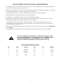
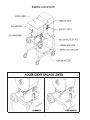
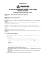
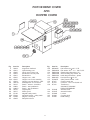
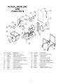
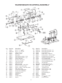
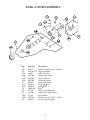
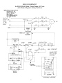
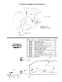
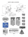
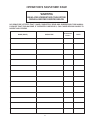
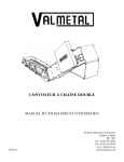
PTCT
MINI-32
299-7-05-2
TABLE OF CONTENTS
Page
SAFETY INSTRUCTIONS . . . . . . . . . . . . . . . . . . . . . . . . . . . . . . . . . . . . . . . . . . . . . . . . . . . . . . 1
SAFETY INSTRUCTIONS . . . . . . . . . . . . . . . . . . . . . . . . . . . . . . . . . . . . . . . . . . . . . . . . . . . . . . 2
INSTALLATION . . . . . . . . . . . . . . . . . . . . . . . . . . . . . . . . . . . . . . . . . . . . . . . . . . . . . . . . . . . . . 3
MOTOR WIRING AND ELECTRICAL REQUIREMENTS. . . . . . . . . . . . . . . . . . . . . . . . . . . . . . . . 4
PRE-OPERATION . . . . . . . . . . . . . . . . . . . . . . . . . . . . . . . . . . . . . . . . . . . . . . . . . . . . . . . . . . . . 5
PARTS LOCATION . . . . . . . . . . . . . . . . . . . . . . . . . . . . . . . . . . . . . . . . . . . . . . . . . . . . . . . . . . . 6
OPERATION . . . . . . . . . . . . . . . . . . . . . . . . . . . . . . . . . . . . . . . . . . . . . . . . . . . . . . . . . . . . . . . . 7
CLEANING . . . . . . . . . . . . . . . . . . . . . . . . . . . . . . . . . . . . . . . . . . . . . . . . . . . . . . . . . . . . . . . . . 8
DISASSEMBLY INSTRUCTIONS . . . . . . . . . . . . . . . . . . . . . . . . . . . . . . . . . . . . . . . . . . . . . . . . . 9
MAINTENANCE & LUBRICATION. . . . . . . . . . . . . . . . . . . . . . . . . . . . . . . . . . . . . . . . . . . . . . . . 10
PARTS LIST DIAGRAMS . . . . . . . . . . . . . . . . . . . . . . . . . . . . . . . . . . . . . . . . . . . . . . . 11-12-13-14
FASTENERS AND LOCATIONS . . . . . . . . . . . . . . . . . . . . . . . . . . . . . . . . . . . . . . . . . . . . . . . . . 15
ELECTRICAL SCHEMATIC . . . . . . . . . . . . . . . . . . . . . . . . . . . . . . . . . . . . . . . . . . . . . . . . . . . . . 16
FOOT SWITCH DIAGRAMS . . . . . . . . . . . . . . . . . . . . . . . . . . . . . . . . . . . . . . . . . . . . . . . . . . . . 17
SAFETY LABEL LOCATIONS . . . . . . . . . . . . . . . . . . . . . . . . . . . . . . . . . . . . . . . . . . . . . . . . . . . 18
OPERATOR SIGNATURE PAGE . . . . . . . . . . . . . . . . . . . . . . . . . . . . . . . . . . . . . . . . . . . . . . . . . 19
LIMITED WARRANTY . . . . . . . . . . . . . . . . . . . . . . . . . . . . . . . . . . . . . . . . . . . . . . . . . . . . . . . . . 20
— OPERATOR'S NOTES —
NOTICE TO OWNERS AND OPERATORS
BIRO’s products are designed to process food products safely and efficiently. Unless the operator is properly trained and supervised, however, there is the possibility of a serious injury. It is the
responsibility of the owner to assure that this machine is used properly and safely, strictly following
the instructions contained in this Manual and any requirements of local law.
No one should use or service this machine without proper training and supervision. All operators should be thoroughly familiar with the procedures contained in this Manual. Even so, BIRO
cannot anticipate every circumstance or environment in which its products will be used. You, the
owner and operator, must remain alert to the hazards posed by the function of this equipment —
particularly the ROTATING GRINDING AUGER and the ROTATING MIXING PADDLE, which can
severely injure an inattentive operator amputating fingers and limbs. No one under eighteen (18)
years of age should operate this equipment. If you are uncertain about a particular task, ask your
supervisor.
This Manual contains a number of safe practices in the SAFETY TIPS section. Additional warnings are placed throughout the Manual. Warnings related to your personal safety are indicated by:
Warnings related to possible damage to the equipment are indicated by:
BIRO also has provided warning labels on the equipment. If any warning label, instruction label
or Manual becomes misplaced, damaged, or illegible, please contact your nearest Distributor or
BIRO directly for a replacement.
Remember, however, this Manual or the warning labels do not replace the need to be alert and
to use your common sense when using this equipment.
THE BIRO MANUFACTURING COMPANY
1114 West Main Street
MARBLEHEAD, OHIO 43440
Phone (419) 798-4451
FAX (419) 798-9106
http: //www.birosaw.com
E-Mail: [email protected]
1
SAFETY TIPS
ROTATING GRINDING AUGER &
ROTATING MIXING PADDLES
TO AVOID SERIOUS PERSONAL INJURY
NEVER Touch This Machine without Training and Authorization by Your Supervisor.
NEVER Place Hands into Machine Input or Output Openings.
NEVER Open Machine During Operation.
ONLY Use a Qualified Electrician to Install According to Local Building Codes: Machine MUST
Be Properly Grounded.
ALWAYS Connect to Proper Voltage & Phase.
ONLY Install on Level, Non-Skid Surface in a Clean, Well-Lighted Work Area Away from
Children and Visitors.
ALWAYS Lock Machine Castors After Moving This Machine.
NEVER Use This Machine For Non-Food Products.
NEVER Operate Machine With Product Mixer Safety Cover Open or Removed or Magnetic
Interlock Switch By-Passed.
ALWAYS Turn Off, Unplug Machine From Power Source and Perform Lockout/Tagout Procedure
to this Machine BEFORE Attempting to Unjam or Unclog, Cleaning or Servicing.
NEVER Leave Machine Unattended While Operating.
NEVER Alter This Machine From its Original Form as Shipped From Factory. DO NOT Operate
Machine With Missing Parts.
PROMPTLY REPLACE Any Worn or Illegible Warning Labels.
ALWAYS Read Operation and Service Manual BEFORE Operating, Cleaning, or Servicing.
USE ONLY BIRO Parts and Accessories Properly Installed.
2
INSTALLATION
TO AVOID SERIOUS PERSONAL INJURY, PROPERLY INSTALL
EQUIPMENT IN ADEQUATE WORK AREA
ALWAYS Use Qualified Technician and Electrician for Installation.
ALWAYS Connect to Proper Voltage & Phase.
ALWAYS Install Equipment in Work Area with Adequate Light and Space Away From Children
and Visitors.
ONLY Operate on a Solid, Level, Non-Skid Surface.
ALWAYS Lock Machine Castors After Moving Machine.
NEVER Bypass, Alter, or Modify This Equipment in Any Way From Its Original Condition.
NEVER Operate Machine With Product Mixer Safety Cover Opened or Removed or Magnetic
Interlock Switch By-Passed.
NEVER Operate Without all Warning Labels Attached and Owner/Operator Manual Available to
the Operator.
UNCRATING AND SET UP
1. Read this Manual thoroughly before installation and operation. Do not proceed with installation and operation if
you have any questions or do not understand anything in this Manual. Contact your local Distributor, or BIRO
first.
2. Remove all banding, shipping carton, and all equipment from inside the tub. Then take machine off shipping
pallet.
3. Install machine on a level, non-skid surface in a well-lighted work area away from children and visitors.
4. This machine is complete except for knife and plate. There is a bowl shipping plug (stamped steel) placed in the
output end of the grinding bowl to retain the grinding auger during shipment. REMOVE THE BOWL SHIPPING
PLUG AND THE GRINDING AUGER.
5. After checking and making sure the power supply is correct, plug in your machine. NEVER OPERATE
MACHINE WITH PRODUCT MIXER SAFETY COVER OPEN OR HOPPER REMOVED. (Machine will not run
with cover open or hopper removed.)
6. Machine must be properly grounded. Use qualified electrician to install according to local building codes.
3
MOTOR WIRING AND ELECTRICAL REQUIREMENTS
1. Interchange of motor current is made in motor outlet box. Leads are properly marked. Changing instructions
are on the motor plate or inside junction box cover.
2. All grinders are wired 220 volts unless otherwise specified. Be sure motor specifications (voltage, cycle, phase)
match power supply line. Be sure line voltage is up to specification.
3. Connect leads to machine in a manner that will be approved by local electrical inspectors.
4. Rated voltage of the unit shall be identical with full supply voltage.
5. Voltage drop on the supply line shall not exceed 10% of full supply voltage.
6. The feederline conductor size in the raceway from the branch circuit to the unit must be correct to assure
adequate voltage under heavy starting and short overload conditions.
7. The feederline conductor shall only be used for the supply of one unit of the relevant horsepower. For
connections of more than one unit on the same feeder line, a local electrician will have to be consulted to
determine the proper conductor size.
8. The size of the electrical wiring required from the power source to the mixer-grinder/chopper is a MINIMUM OF
No. 12 WIRE.
9. The BIRO Manufacturing Company is not responsible for permanent wiring, connection or installation
NOTE TO OWNER AND ELECTRICIAN: IF THIS MACHINE IS NOT CORD
AND PLUG CONNECTED TO THE ELECTRICAL SUPPLY SOURCE, THEN IT
SHOULD BE EQUIPPED WITH, OR CONNECTED TO, A LOCKABLE,
MANUALLY-OPERATED DISCONNECT SWITCH (OSHA 1010.147).
MOTOR SPECIFICATIONS
HP
KW
VOLTS
HZ
PH
AMPS
3
2.5
208/230
60
3
11/9.8
3
2.5
208/230
60
1
19/17
3
2.5
460
60
3
4.9
4
10. The start stop switch and the grind engage lever are located on the right side of the machine when facing the
grinding bowl. The start stop switch will activate the mixer paddles. The start stop switch will also activate the
grinding auger only when the grind lever is in the "engaged" position. To deactivate the grinding operation move
the grind lever to the "disengaged" position. The tank and hopper cover interlock switches are located in the
motor compartment. When the safety cover is raised the machine will stop operation.
PRE-OPERATION AND AUGER ROTATION CHECK
ROTATION MUST ONLY BE CHECKED WITH THE
GRINDING AUGER REMOVED, otherwise serious irreparable
damage may occur to grinding components.
11. Turn the toggle hand/foot selector switch to the hand position and engage the grind lever to activate the grinding
auger. Push the green start button. CHECK THE ROTATION OF THE AUGER DRIVE SHAFT; ROTATION
MUST BE COUNTER-CLOCKWISE as indicated by the rotation decal affixed to the grinding bowl.
12. If machine runs clockwise (backwards), it must be rewired to correct rotation, otherwise serious irreparable
damage may occur to the grinding components.
13. Check operation of optional footswitch provided as needed. Plug footswitch cord into fitting located on the same
side as the operation controls. Move toggle selector to foot. The machine will operate with pressure on the
footswitch treadle. Releasing the treadle stops the machine. The footswitch operates the mix and grind
together.
14. Insert auger assembly into grinding bowl, place knife (sharp edges out) onto the square end of the auger
assembly. The breaker plate slides over the worm knife drive pin, and is held from rotating by pins in the grinder
bowl. Install the retaining ring.
ONLY HAND TIGHTEN RETAINING RING
For best results, use knife and plate as a set. Do not operate machine
for any period of time without product in the grinding bowl. This will
cause heating and dulling of the knife and plate.
15. Check placement of all warning labels and be sure anyone who is to operate this MINI-32 MIXER GRINDER has
read and fully understands the operators manual. Machine is now ready for trained operators to process
product.
16. Use meat deflector attached to grinding bowl to eliminate meat splatter.
17. Contact your local distributor if you have any questions or problems with the installation or operation of this
machine.
5
PARTS LOCATION
6
OPERATION
ROTATING GRINDING AUGER & ROTATING
MIXING PADDLE
TO AVOID SERIOUS PERSONAL INJURY
ONLY Properly Trained Personnel Should Use This Equipment.
NEVER Place Hands Into Machine Input or Output Openings.
NEVER Open Machine During Operation.
DO NOT Wear Gloves While Operating.
DO NOT Tamper With, Bypass, Alter, or Modify This Equipment in Any Way From Its Original
Condition.
NEVER Operate Machine With Product Mixer Safety Cover Opened or Hopper Removed or
Magnetic Interlock Switch By-Passed.
ALWAYS Turn Off and Unplug Machine from Power Source and Perform Lockout/Tagout
Procedure to This Machine Before Unjamming, Unclogging, Cleaning or Servicing, or When Not
in Use.
NEVER Leave Machine Unattended While Operating.
NEVER Operate Without All Warning Labels Attached and Operating Manual Available to the
Operator.
A. TO PROCESS PRODUCT
1. Before starting the mixer-grinder, have a container for receiving ground product at the output end of the
grinding bowl.
2. FIRST GRIND
a. Fill product hopper (maximum 55 pounds), and close Product Mixer Safety Cover.
b. Push the green start button with the selector switch in hand position and shift the grind lever into the
"Engaged" position to feed first grind. It is recommended to use a breaker plate with 3 8" diameter or larger
holes.
c. Push the red stop button and move the grind lever to "Disengaged" position when all product has been
ground out.
3. SECOND GRIND
a. Fill product hopper (maximum 55 pounds), and close Product Mixer Safety Cover.
b. With the grind lever in the "Disengaged" position and the selector switch in hand position, push the green
start button. During this mix operation seasonings may be added through the sight holes in the Product
Mixer Safety Cover, or by lifting Product Mixer Safety Cover.
c. After the desired mix, shift the grind lever into the "Engaged" position to operate grinding auger and grind
out product.
d. Push the red stop button and move the grind lever to "Disengaged" position when all product has been
ground out.
4. Unplug machine from power source and perform lockout/tagout procedures.
7
DO’s
DON’Ts
• Always keep knife & plate as matched set.
• Never, never mix different knives to different
• Always keep the knife & plate sharp.
•
• Always check for straightness by laying the knife
on the plate before inserting in machine.
•
• Always install the knife & plate in correct se-
quence, knife 1st, then plate.
• Always keep knives & plates lubricated in storage
and when starting machine.
• Always use coolant when sharpening plates.
• Always inspect the plates making sure all holes
are clear – that there are no cracks.
•
•
plates.
Never, never over tighten the bowl retaining ring
on the machine.
Never, never run the grinder without product.
Product is a natural lubricant. Heat can build up
so fast that cold product could crack the plate.
Never, never hit the plate against anything to
clean the holes.
Never, never throw the knives & plates.
CLEANING
BEFORE CLEANING OR SERVICING
ALWAYS Turn Off, Unplug Machine From Power Source and Perform Lockout/Tagout Procedure
to This Machine Before Cleaning or Servicing.
ONLY Use Recommended Cleaning Equipment, Materials, and Procedures.
NEVER Spray Water or Other Liquid Substances Directly at Motor, Power Switch or any Other
Electrical Components.
ALWAYS Thoroughly Clean Equipment at Least Daily.
CLEANING THE MINI-32 MIXER GRINDER
1. Disconnect mixer grinder from power source and/or perform lockout/tagout procedures.
2. Remove end ring, breaker plate, knife and grinding auger.
3. Remove mixing paddle, hopper and grinding bowl assembly from machine (see disassembly instructions on the
following page).
4. Machine is now ready to be cleaned using warm soapy water and rinsed with clean water. Machine may be
cleaned by power spray washing, taking care not to spray directly at any electrical controls.
5. The grinding head can be removed for cleaning if desired.
6. After machine has been cleaned and allowed to air dry, all exposed metal surfaces should be coated with a good
food grade light oil or grease.
7. Never wash the clear hopper cover with abrasive cleaners. Use a soft cloth and warm soapy water only.
8
DISASSEMBLY INSTRUCTIONS
PADDLE REMOVAL:
Remove mixing paddle by first locating and lifting up on the hopper lock down clamps releasing them from the hopper. Next loosen the paddle lock knob (black knob located at the
front of the hopper). Then turn the locking lever clockwise approximately ¼ turn and remove
to unlock the paddle shaft from the hopper. Slide paddle shaft toward front of hopper and
lift drive end up and out to remove paddle.
PADDLE INSTALLATION:
Install paddle shaft by first connecting the driven end of the paddle shaft to the driver hub.
Insert the locking lever and tighten the paddle lock knob.
HOPPER REMOVAL:
After the paddle shaft has been removed, be sure the hopper lock down clamps have been
lifted and lock down rods extracted from the hopper anchor releasing them from the hopper.
The hopper is now ready for removal.
HOPPER INSTALLATION:
Place the hopper on top of the grinding bowl assembly with the lock arm retainer facing toward the front of the machine. Connect the hopper lock down rods to the hopper anchors
and lower the lock down handles to lock the hopper in place.
AUGER ASSEMBLY REMOVAL:
Loosen the retaining ring and remove knife and plate. Now the auger can be pulled out from
grinding bowl.
GRINDING BOWL ASSEMBLY REMOVAL:
After the paddle shaft, hopper, retaining ring and auger assembly have been extracted, the
grinding bowl can be removed by lifting the output end of the assembly and pushing toward
the cabinet. Next lift the bowl lock hooks and separate the bowl assembly from the machine.
9
MAINTENANCE
ROTATING GRINDING AUGER &
ROTATING MIXING PADDLE
TO AVOID SERIOUS PERSONAL INJURY
ALWAYS Turn Off, Unplug From Power Source and Perform Lockout/Tagout Procedure to This
Machine BEFORE Servicing.
NEVER Touch This Machine Without Training and Authorization By Your Supervisor.
NEVER Place Hands Into Machine Input or Output Openings.
NEVER Bypass, Alter, or Modify This Equipment in Any Way From Its Original Condition.
PROMPTLY REPLACE Any Worn or Illegible Warning Labels.
USE ONLY GENUINE BIRO Parts and accessories Properly Installed.
LUBRICATION
1. MOTOR: The grinder motor has pre-lubricated motor bearings. These bearings should be re-lubricated
annually with a good grade of bearing grease. Do not over-grease.
2. ROLLER CHAIN AND DRIVE SPROCKETS: The main drive chain has been pre-lubricated at the factory to
protect it against dirt and moisture. Chain life will vary appreciably depending upon its lubrication. The
better the lubrication, the longer the chain life.
Lubrication effectiveness will vary with the amount of lubricant and frequency of application. Ideally, a
lubricant film should always be present between the working parts. Manually lubricate the chain as often as
is needed (possibly once a week). NEVER exceed three months without lubricating.
Lubricating just the outside of the chain does little good. Apply lubrication on the inside of the chain span so
that it will work through the moving parts and joints by centrifugal force as the chain rotates and reaches the
area where one surface “scrubs” another.
Recommended types of chain lubricant are those with Molybdenum Disulphide or Graphite added. Also
bonded lubricants such as Dow Corning Molykote 321R or equivalent are excellent for open chains. The
lubricant should be of a viscosity whereby it will “flow” somewhat and penetrate the internal working surfaces.
Thick stiff greases are of little value because they cannot work into moving parts of the chain.
a. Unplug mixer/grinder from power source and perform lockout/tagout procedures.
b. Remove rear drive or access cover.
c. Spray or brush lubricant on inside of chain, slowly and carefully turning the large sprocket by hand.
d. Reinstall rear drive cover.
10
MOTOR DRIVE COVER
AND
HOPPER COVER
Fig.
9
26
50
51
52
116
116A
117
118
119
120
121
122
123
125
125A
126
127
Item No.
50024
63021
63085
63093
63097
63095
63035
63024
56301G
56105
H482-1
H482-2
56125
56337
PC166
PC044
PC084
63082
Description
Auger drive shaft seal
Nylon bearing cover
Hood, motor & drive unit
Electrical box access panel
Electrical box
Hopper cover – NSS
Hopper cover & arm assembly
Hopper cover arm bracket – NSS
Watertight 90° cord connector
Switch – selector – hand/foot
Switch – start pushbutton
Switch – stop pushbutton
Legend plate
Switch guard
Magnetic safety switch
Mounting bracket – safety switch
Magnet – south pole
Safety lid lock arm
11
Fig.
128
129
130
131
132
133
135
136
137
138
Item No.
HHS086S
EMG92032
EMG62184
EMG62182
EMG62181
HNNL25S
56294CE
PC162
PC144
PC140
139
140
141
142
143
56301D
56301E
56300H
56300J
56302I
Description
Hex head screw 3 8-16 ´ 2, SS
Flat washer .397 ´ 1¼ ´ .120 TH, SS
Outside hinge flat washer, SS
Sleeve bushing step washer, SS
Inside hinge flat washer – plastic
Hex Nylock nut 3 8-16, SS
Safety switch bracket – NSS
Central control unit
Contactor – SP17.10-G0/24V coil
Transformer –
208/240/277/380/480V
PRI/24V SECONDARY
Airswitch w/nut
Airswitch bracket
Locknut
Coupling body
Plastic tubing
Fig.
1
2
3
4
11
12
12A
12B
13
29
31
33
34
Item No.
15026-02
15029
20050-10
20050-01
53568
53852
53517-1
53594
56302
63036
63041
63043
63045
Description
Double roller chain 49"
Double chain master link
#40 Roller chain
#40 Chain master link #40-C/L
Paddle locking thumb screw
Lock arm assembly w/bushings
Thrust bearing
Radial bushing
Foot switch assembly w/6' tubing
Hopper assembly
Sprocket D40B35
Sprocket 40B15F-01
Back access panel
Fig.
35
36
37
38
39
45
46
54
72
115
124
134
12
Item No.
63047
63048-01
63049
63055
63057
63070
63073
63099
63136
H340
PC175
PC085
Description
Timing pulley 48H100SK
Taper lock SK 1"
Timing belt
Cart assembly w/casters
table top leg (optional)
Gear reducer #924DN RT5:1
Mixer paddle assembly
Motor, 3HP/208/230/460V/3PH
Paddle spacer
Ring wrench
Casters w/swivel lock
Magnetic housing – hopper
TRANSMISSION MOUNTING ASSEMBLY
Fig.
5
6
8
10
14
15
16
17
18
19
20
21
22
24
25
28
30
32
40
41
42
43
44
Item No.
20665
20665-01
30315
50029
63005
63007
63008
63009
63010
63011
63014
63015
63016
63019
63020
63033
63040
63042
63062
63063
63065
63066
63067
Description
Key ¼ ´ ¼ ´ 11 8 SS
Key ¼ ´ ¼ ´ 1¾ SS
O-Ring 1.25 I.D.
Washer – brass
Base plate
Shaft bearing retainer – front
Shaft bearing retainer – rear
Frame side plate
Bowl lock side spacer
Gear box top plate
Auger drive shaft
Main drive shaft
Bearing retainer – main shaft
Spacer – mixer drive shaft
Spacer – plastic – mixer drive shaft
Mixer driver shaft
72T sprocket #40B72-01
22T sprocket #D40B22
Linkage pivot arm
Linkage arm
Spacer
Thrust bearing
Spacer
Fig.
47
48
49
55
56
57
58
59
64
65
66
67
68
70
71
73
74
75
76
106
107
108
113
13
Item No.
63081-01
63081-02
63084
56064
56065
56211-1
56214
63104
56215
63119
56127-1
MC-21R2
SSB50P
63126
63127
63139-01
63139-02
63140
63141
83017
83032
83080-07
90509
Description
Bowl support bracket – LH
Bowl support bracket – RH
Hopper latch rod
Drive clutch – square ID
Driving clutch – motor output
Engagement lever bushing
Clutch engagement lever – LH
Link engage handle
Clutch engagement lever – RH
Clutch engagement shaft
Woodruff key
Lock handle groove pin
Shoulder bolt 5 3 8-16 ´ ½
Chain tensioner
Tensioner block
Bowl lock hook – LH
Bowl lock hook – RH
Hopper latch
Bowl adjusting pin
Bearing
Bearing
Key 3 8 ´ 3 8 ´ 1½ LG
Pivot arm knob
BOWL & WORM ASSEMBLY
Fig.
23
60
60A
60B
60C
60D
61
61A
61B
62
63
69
69A
69B
114
Item No.
63017
54278-CTN
HK48
54278B
54278C
54278D
56049
WN20S
SSS45S
HR42/48
57159
57159K
57160
FHS26S
52392
Description
Bowl mounting stud, 2 required
Auger assembly
Knife drive pin
Square drive insert
Auger shear pin
Shear pin screws
Bowl & plate pins
Wing nut 3 8-16
Stud 3 8-16 ´ 1
Ring
Auger drive shaft seal
Auger drive shaft seal kit
Seal retainer
Flat head screw 10-32 ´ ¾ SS
Product splash shield
14
FASTENERS & LOCATIONS
Base Plate (63005) to Cart Assembly (63055)
3 -16 ´ 2¼
4 ea.
HHS088S
8
3 heavy
4 ea.
LW25S
8
3 -16 heavy (with loctite)
4 ea.
HN25S
8
Frame Side Plates (2 ea. 63009) to Base Plate
(63005)
4 ea.
HHS058S 5 16-18 ´ 7 8
5
4 ea.
LW15S
16 regular
5
8 ea.
FW10S
16
Frame Side Plates (2 ea. 63009) to Bearing
Retainer-main shaft-rear (1 ea. 63016)
3 -16 ´ 1¼
4 ea.
HHS075S
8
3 heavy
4 ea.
LW25S
8
Bowl Support Brackets (LH 63081-01 & RH
63081-02) to Bowl Lock Side Spacer (2 ea.
63010) to Frame Side Plates (2 ea. 63009) to
Bearing retainer-main shaft-front (1 ea. 63016)
3 -16 ´ 2½
4 ea.
HHS090S
8
3 heavy
4 ea.
LW25S
8
Bowl Support Brackets (LH 63081-01 & RH
63081-02) to Bowl Lock Side Spacer (2 ea.
63010) to Frame Side Plates ( 2 ea. 63009) to
Shaft Bearing Retainer-front (63007)
3 -16 ´ 2½
4 ea.
HHS090S
8
3 heavy
4 ea.
LW25S
8
Motor (63099) to Shaft Bearing Retainer-rear
(63008)
4 ea.
HHS060S 5 16-18 ´ 1
5
4 ea.
LW15S
16 regular
5
8 ea.
FW10S
16
Bowl Mount Stud (63017) to Bowl (56049)
2 ea.
HHS129S
½-13 ´ 2 (with loctite)
Bowl Support Brackets (LH 63081-01 & RH
63081-02) to Base Plate (63005)
3 -16 ´ 1
2 ea.
HHS070S
8
3 heavy
2 ea.
LW25S
8
3 -16 heavy
2 ea.
HN25S
8
Gear Box Top Plate (63011) to Shaft Bearing
Retainers (Front 63007 & Rear 63008)
3 -16 ´ 1¼
4 ea.
HHS075S
8
3 heavy
4 ea.
LW25S
8
Gear Reducer (63070) to Gear Box Top Plate
(63011)
4 ea.
HHS110S
½-13 ´ 1
4 ea.
LW30S
½
Bowl Lock Hook-LH (63139-01) to Bowl Support Bracket-LH (63081-01)
1 ea.
HHS126S
½-13 ´ 1¼
1 ea.
LW30S
½
Frame Side Plates (2 ea. 63009) to Shaft Bearing Retainer-rear (63008)
3 -16 ´ 1¼
4 ea.
HHS075S
8
3 heavy
4 ea.
LW25S
8
Bowl Lock Hook-RH (63139-02) to Bowl Support Bracket-RH (63081-02)
1 ea.
HHS126S
½-13 ´ 1¼
1 ea.
LW30S
½
Chain Tensioner (63126) to Shaft Bearing Retainer-rear (63008)
2 ea.
HHS055S 5 16-18 ´ ¾
5
2 ea.
LW15S
16 regular
5
2 ea.
FW10S
16
Hopper Latch (2 ea. 63140) to Bowl Support
Bracket (LH 63081-01 & RH 63081-02)
8 ea.
RHS09S
10-32 ´ 3 8 (with loctite)
15
MINI-32 SCHEMATIC
for 208-230/460 Volts, Three Phase, 60 Cycle
with Elobau Magnetic Safety Switches
16
OPTIONAL PNEUMATIC FOOTSWITCH
17
SAFETY LABEL LOCATIONS
18
OPERATOR’S SIGNATURE PAGE
WARNING
READ AND UNDERSTAND THIS ENTIRE
MANUAL BEFORE SIGNING BELOW
MY SIGNATURE ATTESTS THAT I HAVE COMPLETELY READ AND UNDERSTAND THIS MANUAL.
I REALIZE THAT THIS MACHINE, IF OPERATED CARELESSLY, CAN CAUSE SERIOUS INJURY TO
MYSELF AND OTHERS.
NAME (PRINT)
SIGNATURE
19
SUPERVISOR’S
INITIALS
DATE
LIMITED WARRANTY:
WARRANTY: The Biro Manufacturing Company warrants that the BIRO MINI-32 Grinder will be
free from defects in material and workmanship under normal use and with recommended service.
BIRO will replace defective parts, which are covered by this limited warranty, provided that the defective parts are authorized for return, shipping charges prepaid, to a designated factory for inspection and/or testing.
DURATION OF WARRANTY: The warranty period for all parts covered by this limited warranty is
one (1) year from date of inspection/demonstration as advised on the returned Warranty registration card, or eighteen (18) months from original factory shipping date, whichever date occurs first,
except as noted below.
PARTS NOT COVERED BY WARRANTY: The following are not covered by this limited warranty:
wearable parts in the grinding system such as bowl, ring, worm, drive shaft, knife drive pin, bowl
pin, knife and plate. This limited warranty does not apply to machines sold as used, rebuilt, modified, or altered from the original construction in which the machine was shipped from the factory.
(Water contaminated electrical systems are not covered under this limited warranty.) BIRO is not
responsible for electrical connection of equipment, adjustments to the switch controls or any other
electrical requirements, which must be performed only by a certified electrician. BIRO is not responsible for service charges or labor required to replace any part covered by this limited warranty
or for any damages resulting from misuse, abuse, lack of proper or recommended service.
EXCLUSION OF WARRANTIES AND LIMITATION OF REMEDIES: BIRO gives no warranties
other than those expressly stated in this limited warranty. THE IMPLIED WARRANTY OF MERCHANTABILITY, THE IMPLIED WARRANTY OF FITNESS FOR PROCESSING OF FOOD PRODUCTS, AND ALL OTHER IMPLIED WARRANTIES ARE SPECIFICALLY EXCLUDED. BIRO IS NOT
LIABLE FOR CONSEQUENTIAL OR INCIDENTAL DAMAGES, EXPENSES, OR LOSSES. THE
REMEDIES PROVIDED IN THIS BIRO LIMITED WARRANTY ARE PURCHASER’S SOLE AND EXCLUSIVE REMEDIES AGAINST BIRO.
REGISTRATION CARDS: You must sign, date and complete warranty registration card supplied
with each machine. The warranty card must be returned to The Biro Manufacturing Company for
proper registration. If no warranty card is returned to BIRO, the warranty period will begin from
the date the machine was originally shipped from the factory.
HOW TO GET SERVICE:
1. Contact the entity from whom you purchased the machine; or
2. Consult the yellow pages of the phone directory for the nearest authorized dealer; or
3. Contact BIRO Mfg. Company for the authorized service entity (250 plus worldwide) in your area.
THE BIRO MANUFACTURING COMPANY
1114 Main Street
Marblehead, Ohio
Ph. 419-798-4451
Fax 419-798-9106
E-mail: service@biro saw.com
Web: http://www.biro saw.com
ITEM No: 32313-299
Form No. MINI-32-7-05-2
20