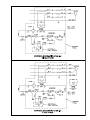
1
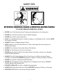
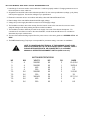
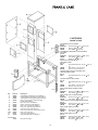
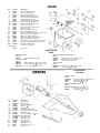
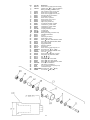
IMPORTANT NOTICE
This Manual contains important
safety instructions which must
be strictly followed when using
this equipment.
PTCT
AFMG-24
220-9-09-14
PPD
220-9-25-14
220-9-05-11
TABLE OF CONTENTS
Page
NOTICE TO OWNERS AND OPERATORS . . . . . . . . . . . . . . . . . . . . . . . . . . . . . . . . . . . . . . . . . . . . . . . . 1
SAFETY TIPS. . . . . . . . . . . . . . . . . . . . . . . . . . . . . . . . . . . . . . . . . . . . . . . . . . . . . . . . . . . . . . . . . . . . . . . . . . . . . . . .2
INSTALLATION . . . . . . . . . . . . . . . . . . . . . . . . . . . . . . . . . . . . . . . . . . . . . . . . . . . . . . . . . . . . . . . . . . . . . . . . . . . . 3
UNCRATING AND SETUP. . . . . . . . . . . . . . . . . . . . . . . . . . . . . . . . . . . . . . . . . . . . . . . . . . . . . . . . . . . 3
MOTOR WIRING AND ELECTRICAL REQUIREMENTS. . . . . . . . . . . . . . . . . . . . . . . . . 4-5
MOTOR SPECIFICATIONS . . . . . . . . . . . . . . . . . . . . . . . . . . . . . . . . . . . . . . . . . . . . . . . . . . . . . . . . . .4
OPERATION. . . . . . . . . . . . . . . . . . . . . . . . . . . . . . . . . . . . . . . . . . . . . . . . . . . . . . . . . . . . . . . . . . . . . . . . . . . . . . . . 6
TO PROCESS PRODUCT. . . . . . . . . . . . . . . . . . . . . . . . . . . . . . . . . . . . . . . . . . . . . . . . . . . . . . . . . . . . .6
CLEANING . . . . . . . . . . . . . . . . . . . . . . . . . . . . . . . . . . . . . . . . . . . . . . . . . . . . . . . .. . . . . . . .. . . . . . . . .. . . . . . . . . 7
MAINTENANCE . . . . . . . . . . . . . . . . . . . . . . . . . . . . . . . . . . . . . . . . . . . . . . . . . . . . . . . . . . . . . .. . . . . . . . . . . . . 8
MIXING PADDLE INSTALLATION. . . . . . . . . . . . . . . . . . . . . . . . . . . . . . . . . . . . . . . . . . . . . . . . . .8
LUBRICATION. . . . . . . . . . . . . . . . . . . . . . . . . . . . . . . . . . . . . . . . . . . . . . . . . . . . . . . . . . . . . . . . . . . . . . . 8
WIRING DIAGRAMS, 1 & 3 PHASE. . . . . . . . . . . . . . . . . . . . . . . . . . . . . . . . . . . . . . . . . . . . . . . . . . . . . . . . .9
PARTS DIAGRAMS . . . . . . . . . . . . . . . . . . . . . . . . . . . . . . . . . . . . . . . . . . . . . . . . . . . . . . . . . . . . . . . . . . . . . . . .10
FRAME & CASE . . . . . . . . . . . . . . . . . . . . . . . . . . . . . . . . . . . . . . . . . . . . . . . . . . . . . . . . . . . . . . . . . . . . 10
MIXER. . . . . . . . . . . . . . . . . . . . . . . . . . . . . . . . . . . . . . . . . . . . . . . . . . . . . . . . . . . . . . . . . . . . . . . . . . . . . . .11
GRINDER. . . . . . . . . . . . . . . . . . . . . . . . . . . . . . . . . . . . . . . . . . . . . . . . . . . . . . . . . . . . . . . . . . . . . . . . . . . 11
POWER TRANSMISSIONS. . . . . . . . . . . . . . . . . . . . . . . . . . . . . . . . . . . . . . . . . . . . . . . . 12-13-14-15
POWER CONTROLS (ELECTRICAL) . . . . . . . . . . . . . . . . . . . . . . . . . . . . . . . . . . . . . . . . . . . . . . 16
RETROFIT AEG CONTACTORS IN CONTROL BOX . . . . . . . . . . . . . . . . . . . . . . . . . . . . . . 17
OPTIONAL STAINLESS STEEL BOWLS, AUGERS & RINGS
(114MM UNGER & ENTERPRISE). . . . . . . . . . . . . . . . . . . . . . . . . . . . . . . . . . . . . . . . . . . . . . . . . . 18
ITEMS REQUIRED FOR TANDEM OPERATION. . . . . . . . . . . . . . . . . . . . . . . . . . . . . . . . . . . . . . . . . .19
FOOTSWITCHES, PNEUMATIC & ELECTRIC . . . . . . . . . . . . . . . . . . . . . . . . . . . . . . . . . . . . . . . .20-21
OPTIONAL EQUIPMENT ILLUSTRATED. . . . . . . . . . . . . . . . . . . . . . . . . . . . . . . . . . . . . . . . . . . . . . . . 22
WARNING LABEL LOCATIONS ON MACHINE. . . . . . . . . . . . . . . . . . . . . . . . . . . . . . . . . . . . . . . . . . 23
TANDEM OPERATION ILLUSTRATION FOR 90º INLET . . . . . . . . . . . . . . . . . . . . . . . . . . . . . . . . 24
TANDEM CONNECTION ILLUSTRATIONS. . . . . . . . . . . . . . . . . . . . . . . . . . . . . . . . . . . . . . . . . . . . . . 25
OPERATOR’S SIGNATURE PAGE. . . . . . . . . . . . . . . . . . . . . . . . . . . . . . . . . . . . . . . . . . . . . . . . . . . . . . . . . 26
OPERATOR’S NOTES. . . . . . . . . . . . . . . . . . . . . . . . . . . . . . . . . . . . . . . . . . . . . . . . . . . . . . . . . . . . . . . . . . . . . . 27
LIMITED WARRANTY . . . . . . . . . . . . . . . . . . . . . . . . . . . . . . . . . . . . . . . . . . . . . . . . . . . . . . . . . . . . . . . . . . . . 28
NOTICE TO OWNERS AND OPERATORS
BIRO’s products are designed to process food products safely and efficiently. Unless the operator is properly trained and supervised, however, there is the possibility of a serious injury. It is the
responsibility of the owner to assure that this machine is used properly and safely, strictly following
the instructions contained in this Manual and any requirements of local law.
No one should use or service this machine without proper training and supervision. All operators should be thoroughly familiar with the procedures contained in this Manual. Even so, BIRO
cannot anticipate every circumstance or environment in which its products will be used. You, the
owner and operator, must remain alert to the hazards posed by the function of this equipment —
particularly the ROTATING GRINDING AUGER and the ROTATING MIXING PADDLE, which can
severely injure an inattentive operator amputating fingers and limbs. No one under eighteen (18)
years of age should operate this equipment. If you are uncertain about a particular task, ask your
supervisor.
This Manual contains a number of safe practices in the SAFETY TIPS section. Additional warnings are placed throughout the Manual. Warnings related to your personal safety are indicated by:
OR
Warnings related to possible damage to the equipment are indicated by:
BIRO also has provided warning labels on the equipment. If any warning label or Manual becomes misplaced, damaged, or illegible, please contact your nearest Distributor or BIRO directly
for a replacement.
Remember, however, this Manual or the warning labels do not replace the need to be alert and
to use your common sense when using this equipment.
This Manual applies to machines with serial number 20200 and higher.
– NOTE –
THE BIRO
MANUFACTURING
COMPANY
“A copy of this manual
is included
with each MODEL AFMG-24
MIXER GRINDER.”
1114 West Main Street
OHIO in
43440-2099
“The descriptions andMARBLEHEAD,
illustrations contained
this manualU.S.A.
are not binding. The manuFAX (419)
798-9106 without updating the manual.”
facturer reserves the right to introduce
any modification
Phone (419) 798-4451
E-Mail: [email protected]
1
SAFETY TIPS
ROTATING GRINDING AUGER & ROTATING MIXING PADDLE
TO AVOID SERIOUS PERSONAL INJURY
NEVER Touch This Machine without Training and Authorization by Your Supervisor.
NEVER Place Hands into Machine Input or Output Openings.
NEVER Open Machine During Operation.
ONLY Use a Qualified Electrician to Install According to Local Building Codes: Machine MUST
Be Properly Grounded.
ALWAYS Connect to Proper Voltage & Phase.
ONLY Install on Level, Non-Skid Surface in a Clean, Well-Lighted Work Area Away from
Children and Visitors.
ALWAYS Lock Machine Castors After Moving This Machine.
NEVER Use This Machine For Non-Food Products.
NEVER Operate Machine With Product Mixer Safety Cover Open or Removed or Magnetic
Interlock Switch By-Passed.
ALWAYS Turn Off, Unplug Machine From Power Source and Perform Lockout/Tagout
Procedure to this Machine BEFORE Attempting to Unjam or Unclog, Cleaning or Servicing
NEVER Leave Machine Unattended While Operating.
NEVER Alter This Machine From its Original Form as Shipped From Factory. DO NOT
Operate Machine With Missing Parts.
PROMPTLY REPLACE Any Worn or Illegible Warning Labels.
ALWAYS Read Operation and Service Manual BEFORE Operating, Cleaning, or Servicing.
USE ONLY BIRO Parts and Accessories Properly Installed.
2
INSTALLATION
TO AVOID SERIOUS PERSONAL INJURY, PROPERLY INSTALL
EQUIPMENT IN ADEQUATE WORK AREA
ALWAYS Use Qualified Technician and Electrician for Installation.
ALWAYS Connect to Proper Voltage & Phase.
ALWAYS Install Equipment in Work Area with Adequate Light and Space Away From Children
and Visitors.
ONLY Operate on a Solid, Level, Non-Skid Surface.
ALWAYS Lock Machine Castors After Moving Machine to Operating Location.
NEVER Bypass, Alter, or Modify This Equipment in Any Way From Its Original Condition.
NEVER Operate With Product Mixer Safety Cover Opened or Removed or Magnetic Interlock
Switch By-Passed.
NEVER Operate Without all Warning Labels Attached and Owner/Operator Manual Available to
the Operator.
UNCRATING AND SET UP
1. Read this Manual thoroughly before installation and operation. Do not proceed with installation and operation if
you have any questions or do not understand anything in this Manual. Contact your local Distributor, or BIRO
first.
2. Remove all banding, shipping carton, and all equipment from inside the tub. Then take machine off shipping
pallet.
3. This machine is shipped with the adjustable legs fully retracted. The legs allow for a height adjustment from the
floor to centerline of bowl 241 2" minimum to 34" maximum.
4. This machine weighs approximately 600 pounds. To avoid accidents block up machine after raising to desired
operating height.
5. The adjustable legs can now be unbolted and lowered to the floor. Replace bolts and tighten securely.
6. Install machine on a level, non-skid surface in a well-lighted work area away from children and visitors.
7. This machine is complete except for knife and plate. There is a bowl shipping plug (stamped steel) placed in the
output end of the grinding bowl to retain the grinding auger during shipment. REMOVE THE BOWL SHIPPING
PLUG AND THE GRINDING AUGER.
8. After checking and making sure the power supply is correct, plug in your machine. NEVER OPERATE
MACHINE PRODUCT MIXER SAFETY COVER OPEN. (Machine will not run with cover open.)
9. Machine must be properly grounded. Use qualified electrician to install according to local building codes.
3
MOTOR WIRING AND ELECTRICAL REQUIREMENTS
1. Interchange of current is made in motor outlet box. Leads are properly marked. Changing instructions are on
the motor plate or motor outlet box.
2. All grinders are wired 220 volts unless otherwise specified. Be sure motor specifications (voltage, cycle, phase)
match power supply line. Be sure line voltage is up to specification.
3. Electrical connections to be in accordance with safety codes and National Electrical Code.
4. Rated voltage of the unit shall be identical with full supply voltage.
5. Voltage drop on the supply line shall not exceed 10% of full supply voltage.
6. The feederline conductor size in the raceway from the branch circuit to the unit must be correct to assure
adequate voltage under heavy starting and short overload conditions.
7. The feederline conductor shall only be used for the supply of one unit of the relevant horsepower. For
connections of more than one unit on the same feederline, a local electrician will have to be consulted to
determine the proper conductor size.
8. The size of the electrical wiring required from the power source to the mixer grinder is a MINIMUM OF No. 10
WIRE.
9. The BIRO Manufacturing Company is not responsible for permanent wiring, connection or installation
NOTE TO OWNER AND ELECTRICIAN: IF THIS MACHINE IS NOT CORD
AND PLUG CONNECTED TO THE ELECTRICAL SUPPLY SOURCE, THEN IT
SHOULD BE EQUIPPED WITH, OR CONNECTED TO, A LOCKABLE,
MANUALLY-OPERATED DISCONNECT SWITCH (OSHA 1010.147).
MOTOR SPECIFICATIONS
HP
5
5
5
5
7.5
7.5
7.5
7.5
7.5
KW
4
4
4
4
5.6
5.6
5.6
5.6
5.6
VOLTS
208/230
208/230
460
550
208/230
220
380/415
460
550
HZ
60
60
60
60
60
50
50
60
60
4
PH
3
1
3
3
3
3
3
3
3
AMPS
13.4/12.6
25/22.8
6.3
5.5
21.5/20
22
12.7/11.6
10
8.5
10. Located on the side of the machine are a green and red pushbutton for activating the internal motor control
contactor. The magnetic interlock switch is mounted under the rear machine cover. It lines up with the magnet
attached to the product mixer safety cover. When the safety cover is raised the machine will stop operation.
11. Push the green start button. CHECK THE ROTATION OF THE MIXING PADDLE; ROTATION MUST BE
COUNTER-CLOCKWISE as indicated by the rotation decal affixed to the mixer paddle front mounting hub.
Backwards operation will not allow mixing paddle to feed product to the grinding auger efficiently
12. Lift slightly the clutch arm and push to the rear of the machine. CHECK ROTATION OF THE AUGER
DRIVESHAFT; ROTATION MUST BE COUNTER-CLOCKWISE as indicated by the rotation decal located on
the grinding bowl. ROTATION MUST ONLY BE CHECKED WITH THE GRINDING AUGER REMOVED,
otherwise serious irreparable damage may occur to grinding components.
13. If machine runs clockwise (backwards), it must be rewired to correct rotation, otherwise serious irreparable
damage may occur to grinding components. Both the auger and the mixing paddle must operate in the same
direction.
14. Check operation of optional footswitch if equipped. Plug footswitch cord into fitting on control panel. Turn
selector lever to foot. The machine will operate with pressure on the footswitch treadle. Releasing the treadle
stops the machine.
15. Insert auger assembly into grinding bowl, place knife (sharp edges out) onto the square end of the auger
assembly. The breaker plate slides over the worm knife drive pin, and is held from rotating by pins in the grinding
bowl. Install the retaining ring.
ONLY HAND TIGHTEN RETAINING RING
For best results, use knife and plate as a set. Do not operate machine for any period of time without product in
the grinding bowl. This will cause heating and dulling of the knife and plate.
16. Check placement of all warning labels and Manual. Machine is now ready for trained operators to process
product.
17. Use meat deflector attached to grinding bowl to eliminate meat splatter.
18. Contact your local Distributor or BIRO directly if you have any questions or problems with the installation or
operation of this machine.
5
OPERATION
ROTATING GRINDING AUGER & ROTATING MIXING PADDLE
TO AVOID SERIOUS PERSONAL INJURY
t 0/-: Properly Trained Personnel Should Use This Equipment.
ONLY Properly
Trained
Should
Use ThisOpenings.
Equipment.
t /&7&3
Place Hands
IntoPersonnel
Machine Input
or Output
t /&7&3
During
Operation.
NEVEROpen
PlaceMachine
Hands Into
Machine
Input or Output Openings.
t %0 /05 Wear Gloves While Operating.
NEVER Open Machine During Operation.
t %0 /05 Tamper With, Bypass, Alter, or Modify This Equipment in Any Way From Its Original
Condition.
DO NOT Wear Gloves While Operating.
t /&7&3
Operate
Machine
With Product
Mixer
Safety
Cover
OpenedinorAny
Removed
or Magnetic
Alter, or
Modify
This
Equipment
Way From
Its Original
DO NOT
Tamper
With, Bypass,
Interlock
Switch By-Passed.
Condition.
t "-8":4 Turn Off and Unplug Machine from Power Source and Perform Lockout/Tagout
With Product
MixerUnclogging,
Safety Cover
Opened
Removed or Magnetic
Procedure
NEVER Operate
MachineBefore
to This Machine
Unjamming,
Cleaning
or or
Servicing.
Interlock
Switch
By-Passed.
t /&7&3 Leave Unattended While Operating.
t /&7&3
Operate
Without
All Warning
Labels
Attached
and Owner/Operator
Manual Available to
and Unplug
Machine
from
Power Source
and Perform Lockout/Tagout
ALWAYS
Turn Off
the
Operator.to This Machine Before Unjamming, Unclogging, Cleaning or Servicing.
Procedure
NEVER Leave Unattended While Operating.
A. TO PROCESS PRODUCT
1.
NEVER
All Warning
Labels Attached
and Owner/Operator
Available
BeforeOperate
starting Without
mixer grinder,
have a container
for receiving
ground product atManual
the output
end ofto
the
thegrinding
Operator.
bowl.
2. FIRST GRIND
A. TO
PRODUCT
a. PROCESS
Fill Product Hopper
(Maximum 140 Pounds), close Product Mixer Safety Cover.
Pushstarting
the green
button
shift theforclutch
armground
into the
grindatposition
feed
grind. It is
1. b.Before
mixerstart
grinder,
haveand
a container
receiving
product
the outputtoend
of first
the grinding
bowl.
recommended to use a breaker plate with 3/8” diameter or larger holes.
c.
Push
the red stop button and pull the clutch arm out of the grind position when all product has been
2. FIRST GRIND
ground out.
a. Fill Product Hopper (Maximum 140 Pounds), close Product Mixer Safety Cover.
3. SECOND GRIND
Push the green start button and shift the clutch arm into the grind position to feed first grind. It is
a.b. Fill
Product Hopper (Maximum 140 Pounds), close Product Mixer Safety Cover.
recommended to use a breaker plate with 3 8" diameter or larger holes.
b. Push the green start button. During this mix operation seasonings may be added through the sight
c. Push the red stop button and pull the clutch arm out of the grind position when all product has been
holes
in the Product Mixer Safety Cover.
ground out.
c. After the desired mix, shift the clutch arm into the grind position to operate grinding auger and
3. SECOND GRIND
grind out product.
a. Push
Fill Product
Hopper
(Maximum
140all
Pounds),
close
Mixer Safety
d.
the red
stop button
when
product
hasProduct
been ground
out. Cover.
4. Unplug
powerstart
source
andDuring
perform
procedures.
b. Pushfrom
the green
button.
this lockout/tagout
mix operation seasonings
may be added through the sight holes
in the Product Mixer Safety Cover.
DO’s
DON’Ts
t "MXBZT c.
LFFQ
LOJGF
QMBUF BTmix,
NBUDIFE
t /FWFS
OFWFS
EJĊFSFOU
LOJWFTauger
UP EJĊFSFOU
QMBUFT
After
thedesired
shift TFU
the clutch arm into the grind
position
toNJY
operate
grinding
and grind
out
t "MXBZT LFFQ
UIF LOJGF QMBUF TIBSQ
t /FWFS OFWFS PWFS UJHIUFO UIF CPXM SFUBJOJOH SJOH PO UIF
product.
t "MXBZT DIFDL GPS MFWFMOFTT CZ MBZJOH UIF LOJGF PO UIF QMBUF
machine.
d. Push the red stop button when all product has been ground out.
before inserting in machine.
t /FWFS OFWFS SVO UIF HSJOEFSNJODFS XJUIPVU QSPEVDU 1SPEVDU
t "MXBZT
JOTUBMM UIF
LOJGF
QMBUF
JO DPSSFDU
TFRVFODF
LOJGF TU
is a natural lubricant. Heat can build up so fast that cold
4. Unplug
from
power
source
and perform
lockout/tagout
procedures.
then plate.
product could crack the plate.
t "MXBZT LFFQ LOJWFT QMBUFT MVCSJDBUFE JO TUPSBHF BOE XIFO
t /FWFS OFWFS IJU UIF QMBUF BHBJOTU BOZUIJOH UP DMFBO UIF IPMFT
starting up machine.
t /FWFS OFWFS UISPX UIF LOJWFT QMBUFT
t "MXBZT VTF DPPMBOU XIFO TIBSQFOJOH QMBUFT
t "MXBZT JOTQFDU UIF QMBUFT NBLJOH TVSF BMM IPMFT BSF DMFBS o UIBU
there are no cracks.
6
CLEANING
ROTATING GRINDING AUGER & ROTATING MIXING PADDLE
TO AVOID SERIOUS PERSONAL INJURY
ALWAYS Turn Off, Unplug From Power Source and Perform Lockout/Tagout Procedure to
This Machine Before Cleaning or Servicing.
ONLY Use Recommended Cleaning Equipment, Materials, and Procedures.
NEVER Spray Water or Other Liquid Substances Directly at Motor, Power Switch or any Other
Electrical Components.
ALWAYS Thoroughly Clean Equipment at Least Daily.
CLEANING THE BIRO MIXER GRINDER
1. Disconnect mixer grinder from power source and perform lockout/tagout procedures.
2. Remove grinding bowl end ring, breaker plate, knife and grinding auger.
3. Remove mixing paddle. Be sure front most paddle arm is pointing up. Loosen the thumb screw on the mixer
paddle lock arm (Item No. 53853). While supporting the mixing paddle, remove the lock arm. Turn the mixing
paddle counterclockwise, slide forward to disengage from drive shaft and lift from product hopper.
DO NOT POWER SPRAY DIRECTLY AT ELECTRICAL COMPONENTS
4. Machine is now ready to be cleaned using warm soapy water and rinsed with clean water. Machine may be
cleaned by power spray washing, taking care to not spray directly at any electrical controls.
5. After machine has been cleaned and allowed to air dry, all exposed metal surfaces should be coated with a good
food grade light oil or grease.
CLEANING THE BOWL - RING AND WORM
CARE OF TIN COATED PRODUCTS
(DO’S AND DON’TS)
1. Do not use abrasive cleaning materials, such as brillo pads or metal scrapers. Tin is a soft metal and should be
cleaned with a soft cloth and dried.
2. Do not use a cleaning agent containing a high percentage of free alkali or acid.
3. Do not use a detergent containing a high percentage of tri-sodium phosphate or meta-silicate.
Tin is reactive to both.
4. Rinse well and dry throughly after washing to remove agents that may be reactive to tin.
5. If sterilizing agent containing chlorine is used, the tinned surface must be throughly rinsed.
Chlorine is corrosive to tin.
6. Dry throughly after rinsing and store in a dry environment.
7. If water is exceptionally hard, drying will be necessary to prevent spotting.
7
MAINTENANCE
ROTATING GRINDING AUGER & ROTATING MIXING PADDLE
TO AVOID SERIOUS PERSONAL INJURY
ALWAYS Turn Off, Unplug from Power Source and Perform Lockout/Tagout Procedures to
This Machine BEFORE Servicing.
NEVER Touch This Machine Without Training and Authorization By Your Supervisor
NEVER Place Hands Into Machine Input or Output Openings.
NEVER Bypass, Alter or Modify This Equipment in Any Way From Its Original Condition.
PROMPTLY REPLACE Any Worn or Illegible Warning Labels.
USE ONLY GENUINE BIRO Parts and Accessories Properly Installed.
A. MIXING PADDLE INSTALLATION
1. Check that mixer paddle drive pin (Item No. 53516) in the mixer paddle drive shaft (Item No. 53955) is
positioned vertically.
2. Holding the mixing paddle by the center shaft and with the front blade up carefully fit drive receiving collar
onto the end of the drive shaft. Insert paddle lock arm assembly (Item No. 53852) into the front of the mixing
tub and onto the front of the mixing paddle.
3. When fully seated, turn the lock arm counterclockwise so the protruding arm is behind the lock set screw
bracket. Tighten the mixer paddle lock set screw (Item No. 53568).
B. LUBRICATION
1. MOTORS: This machine utilized prelubricated motor bearings. These bearings should be relubricated
annually with a good grade of bearing grease. Do not over-grease.
2. MAIN BEARINGS: The main bearings are housed in an enclosed and sealed journal box. Relubricate
semi-annually with a good grade of bearing grease. Do not over-grease.
3. TRANSMISSIONS: This machine is equipped with two Euclid gear reducer transmissions – one for the mixer
drive (No. 300V) and one for the auger drive (No. CH300V). The mixer drive (300V) and the auger drive
(CH300V) hold 1¼ pints of oil. This amount brings the lubricant level up to the side "fill level" hole. Oil
should be changed after six (6) weeks of operation initially and subsequently every six (6) months thereafter
using Mobil Gear 630 oil or Mobil 600W Super cylinder oil.
8
9
FASTENERS
FRAME & CASE
Fig.
1
2
3
4
Item No.
56250
56240
56062
56274
5
6
7
8
9
10
10A
11
12
56165
56164
56239
56238
56155
56089
56338
56161
56144
NOT SHOWN
14572
ADJUSTABLE LEGS TO FRAME
Item #
HHS067S
Hex head screw 3 8-16 3 4, SS, (8 ea.)
HN35S
Hex nut, 3 8-16, SS, (8 ea.)
LW25S
Lock washer, 3 8, SS, (8 ea.)
TRANSMISSION MOUNTING PLATE SUPPORTS
TO FRAME
Item #
HHS075S
Hex head screw 3 8-16 11 4, SS, (4 ea.)
LW25S
Lock washer, 3 8, SS, (4 ea.)
S217C
Dowel pin, 5 16 3 4, (4 ea.)
SIDE PANEL FILLER PLATE TO
SIDE DRIVE COVER
Item #
2563
Hex washerhead screw, 10-32 1 2, SS, (8
ea.)
LW05S
Lock washer, #10, SS, (8 ea.)
HN10S
Hex nut, 10-32, SS, (8 ea.)
CONTROL BOX COVER TO CONTROL BOX
THROUGH DRIVE COVER
Item #
2563
Hex washerhead screw, 10-32 1 2, SS,
(12 ea.)
CONTROL BOX TO SIDE COVER
Item #
2563
Hex washerhead screw, 10-32 1 2, SS, (2
ea.)
LW05S
Lock washer, #10, SS, (2 ea.)
HN10S
Hex nut, 10-32, SS, (2 ea.)
DRIVE COVER BACK TO DRIVE COVER
Item #
HHS025S
Hex head screw 1 4-20 1 2, SS, (6 ea.)
LW10S
Lock washer, 1 4, SS, (6 ea.)
DRIVE COVER TOP TO DRIVE COVERS
Item #
HHS025S
Hex head screw 1 4-20 1 2, SS, (4 ea.)
LW10S
Lock washer, 1 4, SS, (4 ea.)
LOWER FRONT COVER TO SIDE DRIVE COVERS
Item #
HHS025S
Hex head screw 1 4-20 1 2, SS, (4 ea.)
LW10S
Lock washer, 1 4, SS, (4 ea.)
DRIVE COVER SIDES TO FRAME
Item #
HHS025S
Hex head screw 1 4-20 1 2, SS, (4 ea.)
LW10S
Lock washer, 1 4, SS, (4 ea.)
DRIVE COVER SIDES TO TUB
Item #
HHS055S
Hex head screw, 5 16-18 3 4, SS, (6 ea.)
LW15S
Lock washer, 5 16, SS, (6 ea.)
FW10S
Flat washer, 5 16, SS, (6 ea.)
Description
Adjustable leg assembly std., S/N 20200 on
Frame fabricated stainless steel, S/N 20200 on
Transmission mounting plate supports (2 req.)
Drive cover top w/prox. switch mounting
bracket, S/N 20200 on
Rear drive cover, S/N 20026 on
Seal for control box, S/N 20026 on
Drive cover, left side, S/N 20200 on
Drive cover, right side, S/N 20200 on
Control box cover, S/N 20026 on
Drive cover lower front, w/lug holder cutouts
Drive cover lower front
Control box, S/N 20026 on
Side panel filler plate S/N 20026 on
Ring wrench hanger
10
MIXER
Fig.
1
2
3
4
5
6
7
7A
7B
8
9
10
11
12
13
14
15
16
17
18
19
19A
Item No.
53568
53594
53517
53852
53953
56039
56040
56121
56124
56044
56045
56072
56073
56074
56284
56221
56222
52181
53853
56230
56273
56273-1
NOT SHOWN
14572
Description
Mixer paddle lock set screw
Lock arm radial bearing
Lock arm thrust bearing
Mixer paddle lock arm assembly
Seal, mixer drive shaft thru tub
Product mixer safety cover
Product mixer tub, no side inlet
Product mixer tub, RH side inlet
Product mixer tub, LH side inlet
Safety cover hinge rod
Safety cover hinge rod spacer (2)
Safety cover latch
Latch mounting bracket, LH
Latch mounting bracket, RH
Product mixer paddle, 1st grind, SS, less hook
Safety cover torsion spring, RH
Safety cover torsion spring, LH
Safety cover magnet up to s/n 21700
Mixer paddle lock arm assembly
Product mixer paddle, 2nd grind, SS, w/hook
Magnet mounting bracket up to s/n 21700
Magnetic switch bracket
& magnet, s/n 21700 on
Ring hanger
FASTENERS
MIXER
HINGE ROD ENDS
Item #
AN20S
Acorn nut, 3 8-16, SS, (2 ea.)
LID LATCH TO LID
Item #
RHS24S
Round head screw, 1 4-20 1 2, SS, (2 ea.)
RHS31S
Round head screw, 1 4-20 1, SS, (1 ea.)
HNNL15S
Hex nut, nylok, 1 4-20, SS, (3 ea.)
MAGNET TO MOUNTING BRACKET
Item #
FHS24S
Flat head screw, 10-32 5 8, SS, (1 ea.)
LW05S
Lock washer, #10, SS, (1 ea.)
HN10S
Hex nut, 10-32, SS, (1 ea.)
TUB TO FRAME
Item #
HHS067S
Hex head screw 3 8-16 3 4, SS, (4 ea.)
LW25S
Lock washer, 3 8, SS, (4 ea.)
FASTENERS
FASTENERS
GRINDER
GRINDER
BOWL
TO TUB
BOWL
TO TUB
ItemItem
# #
3 , SS, (6 ea.)
3 -163 3 ,
HHS067S Hex Hex
screw
HHS067S
headhead
screw
8-16
4 (6 ea.)
8
4 SS,
3 , SS, (6 ea.)
3 , SS,
LW25S LockLock
washer,
LW25S
washer,
8 (6 ea.)
8
5
3
5
3
Dowel
, (2 ea.)
16641664
Dowel
pin, pin,
(2 4ea.)
16 16
4, BOWL
TO TORQUE
BOWL
TO TORQUE
LINKLINK
ItemItem
# #
1 -13
3
1 -13
3
HHS126-GR5
screw,
HHS126-GR5
Hex Hex
headhead
screw,
2 4, 4,
2
grade
(2 ea.)
type type
316 316
grade
5 (2 5ea.)
1 , SS, (2 ea.)
1 , SS,
LW30S LockLock
washer,
LW30S
washer,
2 (2 ea.)
2
Fig.
Item No.
1
HK48
2
HR42/48
Fig.
Item
No.
3
52392
WN20S
14
HK48
SSS45S
25
HR42/48
57159K
36
52392
57159
46A
WN20S
57160
56B
SSS45S
FHS26S
66C
57159K
7
54278-CTN
6A
57159
8
54278B
6B
57160
9
54278D
6C
FHS26S
10
54278C
7
54278-CTN
11
56049
8
54278B
12
56067
9
54278D
13
H340
10
54278C
11
56049
NOT SHOWN
12
56067
HP48
13
HP48
H340
14
H340
Description
Knife drive pin
Bowl end ring
Description
Product splash shield
Wing drive
nut, 3pin
8-16
Knife
3 -16 1
Stud,end
8
Bowl
ring
Auger drive
shaft
seal kit
Product
splash
shield
Augernut,
drive3 8-16
shaft seal, double lip
Wing
3 -16 1SS
Seal retainer,
Stud,
8
Flat head
3 4, SS
Auger
drivescrew,10-32
shaft seal kit
assembly
Auger drive
shaft seal, double lip
Square
drive insert
Seal
retainer,
SS
Shear
pin screw,10-32
screw
Flat
head
3 4, SS
Auger assembly
shear pin
Grindingdrive
bowlinsert
Square
Torquepin
link,
(2 req.)
Shear
screw
Ring wrench
(not shown)
Auger
shear pin
Grinding bowl
Torque link, (2 req.)
Bowl plate
Bowl
platepins
pins (3 req.)
Ring wrench
Ring
wrench
14
11
35,
23, 24, 35, 37
FASTENERS
POWER TRANSMISSION
MIXER TRANSMISSION TO MOUNTING PLATE
Item #
HHS126-GR5 Hex head screw 1 2-13 11 4, SS, (4 ea.)
LW30S
Lock washer, 1 2, SS, (4 ea.)
S217C
Dowel pin, 5 16 3 4, (2 ea.)
GRINDER TRANSMISSION TO MOUNTING PLATE
Item #
HHS126-GR5 Hex head screw 1 2-13 11 4, SS, (4 ea.)
LW30S
Lock washer, 1 2, SS, (4 ea.)
S217C
Dowel pin, 5 16 3 4, (2 ea.)
TRANSMISSION MOUNTING PLATE TO
MOUNTING PLATE SUPPORTS
Item #
HHS075S
Hex head screw 3 8-16 11 4, SS, (6 ea.)
LW25S
Lock washer, 3 8, SS, (6 ea.)
S217C
Dowel pin, 5 16 3 4, (2 ea.)
MOTOR TO TRANSMISSION
Item #
HHS126S
Hex head screw, 1 2-13 11 4, SS, (4 ea.)
LW30S
Lock washer, 1 2, SS, (4 ea.)
LOVEJOY COUPLING TO TRANSMISSION SHAFTS
Item #
1673
Set screw, 1 4-20 1 2, SS, (4 ea.)
JOURNAL BOX TO MOUNTING PLATE
Item #
HHS070S
Hex head screw 3 8-16 1, SS, (4 ea.)
LW25S
Lock washer, 3 8, SS, (4 ea.)
S217C
Dowel pin, 5 16 3 4, (2 ea.)
DRIVING CLUTCH MOTOR OUTPUT TO
TRANSMISSION SHAFT
Item #
SSS17KL
Set screw, knurled, 5 16-18 3 8, SS, (3 ea.)
TORQUE LINK TO JOURNAL BOX
Item #
HHS126-GR5 Hex head screw, 1 2-13 3 4, type 316, grade
5, (2 ea.)
LW30S
Lock washer, 1 2, SS, (2 ea.)
CLUTCH ENGAGEMENT ARM TO CLUTCH ARM LOCK
Item #
SSB50P
Shoulder bolt, 3 8-16 3 8,, (2 ea.)
TRANSMISSION BRACE
Item #
HHS126-GR5 Hex head screw, 1 2-13 3 4, (4 ea.)
LW30S
Lock washer, 1 2, SS, (2 ea.)
12
Fig.
1
2
3
4
5
6
7
8
9
10
11
12
13
14
15
16
17
17A
17B
18
19
20
21
22
23
24
25
26
28
29
30
31
32
33
34
35
36
37
38
39
40
41
42
43
44
45
46
Item No.
Description
56211-1
Driven clutch engagement lever bushing
SSB50PS
SSB50P
Shoulder bolt, 1 2 dia. 3 8 lg. S/N 20405 on
H310A
Bearing assembly (journal box front)
53785
Seal, journal box (front, auger drive)
56036
Driven clutch engagement shaft
56215
Driven clutch engagement lever, RH
56047
Mounting plate for transmission
56063
Journal box housing
56064
Driven clutch, square I.D.
56065
Driving clutch, motor output
56066
Auger drive shaft, SS
56068
Spacer (rear journal box)
56081
Journal box assembly complete
56095
Transmission, grinder, 60HZ
56096
Transmission, grinder, 50HZ
56097
Transmission, mixer
56276A
Coupling assembly complete
56276
Coupling half
56276B
Coupling sleeve
56100A
Bearing assembly (journal box rear)
56101
Castellated lockwasher
56102
Locknut
56103
Seal (rear journal box)
53993
Grease fitting, vented
56287
Motor 71 2HP, 3PH, 208-230/460V, 60HZ
56286
Motor 5HP, 3PH, 208-230/460V, 60HZ
56270
Link engage handle
56288
Engage handle lock
53516
Mixer drive shaft pin
56127-1
Woodruff key
56214
Driven clutch engagement lever, LH
HHS061S Hex head screw, 5 16-18 11 4, SS
56169
Driven clutch engagement shaft collar
SSS10Z
Set screw, 1 4-20 1 4
56258
Driving clutch Delrin back up spacer
56188
Motor 5HP, 1PH, 208-230V, 60HZ
56133
Key, 316 316 11114/8
56132
Key, 1 4 1 4 11 2
56259
Motor 5HP, 3PH, 575V, 60HZ
56260
Motor 71 2HP, 3PH, 575V, 60HZ
56283
Motor 71 2HP, 3PH, 220/380-415V, 50HZ
MC-21R2
Groove pin, S/N 20389 on
53659
Flat washer, S/N 20405 on
ST73
Lock nut spanner wrench (shop tool)
56351
Transmission brace
HHS126-GR5 Hex head screw, 1 2-13 3 4 (4 ea.)
LW30S
Lock washer, 1 2, SS, (2 ea.)
13
14
56097-A
56097-B
5 60 9 7 - B B
5 60 97 -C
56 09 7- D
5 60 97 -DD
5 60 97 -E
56 09 7- F
56 09 7- G
5 60 97 -H
56 09 7- J
Output cap
1
8-16 1 4 hex head cap screws
3 -16 lock washers
8
O ut put g ask e t
5 -18 1 hex head cap screw
16
5 -18 lock washers
16
D e a d i n p ut c ap
In put g ask et
Mounting base
Output shaft
Bearing assembly
3
56097-K
56097-L
56097-M
56097-M
56097-N
56097-O
56097-P
56097-Q
56097-Q
56097-R
56097-S
L iv e i n pu t ca p
Se al
Input worm 60 Hz.
Input worm 50 Hz.
Housing
Freeze plug
Bearing assembly (14276/14125A)
Worm gear – 60 Hz.
Worm gear – 50 Hz.
Ke y ¼ ¼ 2
S e al
15
56095-A
5 6 09 5 - AA
5 60 95 -B
5 60 95 -C
56 095-D
5 60 95 -E
5 6 0 9 5 -E E
5 60 95 -F
5 60 96 -F
5 60 95 -G
5 60 95 -H
56 095-J
56 095-K
8
8
-16 11 4 hex head cap screws
-16 lock washer
O u tp ut c a p
Fr e e z e pl ug
Motor flange
5 -18 1 hex head cap screw
16
5 -18 lock washer
16
Input worm – 60 Hz
Input worm – 50 Hz
Mounting base flange
Output shaft
G as k e t k it c o m p l e t e
Bearing assembly (14276/14125A)
3
3
5 60 95 -L
56 09 6- L
5 60 95 -M
56095-N
56095-O
56095-P
56095-Q
56095-R
56095-S
56095-T
56095-U
56095-V
56095-W
Worm gear 60 Hz.
Worm gear 50 Hz
Ke y – 1 4 1 4 2
Housing
Gaskets
Seals
Gasket
Seal
Bearing
Snap ring
Input cap
Snap ring
Output seal/journal box
POWER
CONTROLS
Fig.
1
2
3
4
5
6
7
8
9
10
11
12
13
14
15
16
17
Item #
50768
50769
51991
56301G
56155
53689
53851
56105
42MC-Y64
56331
Description
Switch, start, pushbutton (order H482-1)
Switch, stop, pushbutton (order H482-2)
Fuseholder
Watertight 90° cord connector
Cover control panel
Cable connector assembly (2 req’d)
Fuse, 1 amp, 250V
Switch, selector, hand/foot
Magnetic safety interlock switch 240V
Magnetic starter contactor AEG-SP37.10-A0;
5HP, 1 Ph, 208-230V, 60Hz; 71 2HP, 3Ph,
208-230/460V, 60Hz, 71 2HP, 3Ph,
220/380-415-50Hz
H281AE-31 Overload AEG-B27T-N, 5HP, 208-230V, 60Hz,
3Ph; 7.5HP, 380-415V, 50Hz, 3Ph; range
11-17 amps
56110
Transformer, 220-440/110
35374
Terminal block – 4 req. (#223)
H281AE-32 Overload AEG-B27T-0; 71 2HP, 220V, 50Hz,
3Ph; Range 15-23 amps
56125
Legend plate (controls)
56294
Safety switch bracket S/N 20307 on
(order 42MC-Y70)
35067
Grommet, wire to safety switch
Fig.
18
19
20
21
22
23
24
25
26
27
28
29
30
31
16
Item *
Description
H481AE-52 Overload; AEG-B27T-L; 5HP; 460-575V, 60Hz,
3Ph; range 5.6-8 amps
H481AE-53 Overload; AEG-B27T-M; 71 2HP; 575V, 60Hz,
3Ph; 71 2HP, 460V, 60Hz; range 8-12 amps
35375
Terminal block end cap (#230)
H281AE-331 Overload, AEG-B77S-P-32A; 5HP, 208-230V,
60Hz, 1Ph; 71 2HP, 208-230V, 60Hz, 3Ph; range
22-32 amps
42MC-AE84 Magnetic starter contactor, AEG-SP27.10-A0;
5HP, 208-230/460V, 60Hz, 3Ph; 5HP, 575V,
60Hz, 3Ph
56261
Transformer 575V/115V
56337
Shroud, selector switch
56339
24 volt magnetic starter contactor
AEG-SP37.10-G0; 71 2HP, 3Ph, 380-415V,
50Hz
55048
Transformer 380V/24V (order BES-16257)
55053
Magnetic safety interlock switch 250-600V
(order H442-1) (24 volt system)
56317
3 amp fuse for 24 volt system
35241
Mount rail, terminal block
35376
End anchor, terminal block
56164
Control box seal
RETOFIT FOR AEG CONTACTORS
RETROFIT
FORBOX
AEGSERIAL
CONTACTORS
IN AFMG-24
CONTROL
NO. 20001 ON
IN AFMG-24 CONTROL BOX
The magnetic contactors and overloads in the
AFMG-24 have been changed to AEG electrical components starting with Serial No. 20260 (5HP) and
Serial No. 20990 (7.5HP). These controls are interchangeable with the old controls with some minor
modifications. Use the following kit numbers when
magneticwith
contactors
replacing previous The
contactors
AEG. and overloads
in the AFMG-24 have been changed to
17
56330K
AEG electrical
components.
Contactor
Kit (5HP-3PH)
110VThese
Coil con-
56331K
Contactor
controls Kit
with(7.5HP-3PH,
some minor 5HP-1PH)
modifications.
110V
UseCoil
the following kit numbers when re-
56339K
placing Kit
previous
contactors24V
with
AEG.
Contactor
(7.5HP-3PH)
Coil
Kit Includes:
Contactor,
Subplate,
and Fasteners
Kit Includes:
Contactor, Sublate,
and Fasteners
Tool Req.:
Tool Req.: Screwdriver
Screwdriver
trols are interchangeable with the old
OPTIONAL
STAINLESS STEEL
BOWLS, AUGERS & PINS
114mm UNGER SYSTEM
ENTERPRISE SYSTEM
Item No.
Description
HHS012S
Hex head screw, 10-32 1 2, SS
HK114
Knife drive pin, 114mm Unger
HR42/48S-114 End ring, SS, 114mm Unger
54278C
Auger shear pin
54278D
Shear pin fastener
54278-CTNS-114
Auger assembly, SS, 114mm
Unger
56049SK-114 Key, 114mm Unger
56049S-114 Bowl, SS, 114mm Unger
HR42/48S
End ring, SS
54278-CTNS Auger assembly, SS
56049S
Bowl w/plate pins, SS
18
ITEMS REQUIRED FOR TANDEM OPERATION
19
20
OPTICAL PNEUMATIC
FOOT SWITCH
NO. 56304
21
224-2
52654
56292
52661
52668
53693
53693-A
53693-C
53693-D
53693-E
53693-F
53693-G
53693-H
53693-I
53693-M
53693-O
53693-T
53693-U
53693-W
53693-X
53979-1
54213
FOOTSWITCH
LIST
Cord co
nnector, wt, straight,PARTS
3/4”
cor
5
wir
Male
plug
w/6’
d,
e
224-2
Cord connector, wt, straight, 3 4"
emale receptaMale
cle,plug
F52654
90º w/6’ cord, 5 wire
cord,receptacle,
5 wire 5 pole
Male
Female
52655plug w/12’
ootswitch w/12’
cor
F52661
d
and plug
Male plug w/12’
cord, 5 wire
ootswitch Footswitch w/12’ cord and plug
F52668
Co
er
guar
v
d
Footswitch
53693
Co
ver gasket Cover guard
53693-A
ver screw –Cshor
t a s ke t
Co
53693-C
ove r g
ver screw –Clo
Co
53693-D
ovng
er screw – short
ound screwCover screw – long
Gr
53693-E
T
readle spring
53693-F
Ground screw
Internal assembl
53693-G
Treaydlco
e smplete
pring
A
ctuator
53693-H
Internal assembly complete
Micr
h
B
o
switc
A-2R62-A4
Actuator
53693-I
asher
W
53693-M
Micro switch BA-2R62-A4
readle w/actuator
T53693-O
Washer& return spring
A
dle retur
uxiliar y treaTreadle
n spring& return spring
53693-T
w/actuator
readle
T
53693-U
Auxiliary treadle return spring
One
actuator Trea
spring assembly
& adctuator
53693-W
le
Cor
w/o
f
h
d
8’
oot
switc
One actuator & actuator spring assembly
53693-X
F54213
d &w/6’
plug
oot switch w/6’
Footcor
switch
cord & plug
FOOTSWITCH PARTS LIST
OPTIONAL
22
23
SAFETY LABEL LOCATIONS
TANDEM OPERATION ILLUSTRATION FOR 90º INLET
24
CONNECTION INSTRUCTIONS
TANDEM OPERATIONS
BIRO AFMG-24 into BIRO AFMG-24
BIRO Heavy Horsepower Grinder into BIRO AFMG-24
Remove Side Entrance Seal, Item No. 56167; Outer Disc, Item No. 54303 and
Lock Knobs, Item No. 14688 from the inlet tube of the Second Grind Machine.
Clean out the tube if necessary.
Install the Inlet Tube Seal Item No. 53671 or 53933 into the
inlet tube of the Second Grind Machine until fully seated. Bolt
the supplied connecting angle to the inlet tube.
Remove the Ring from the First Grind Machine, Item No. HR42/48, HR52 or
HR56. Insert the Item No. 56137, 56135 or 56136 Discharge Horn into the
Ring. Reinstall the ring on the machine.
Insert the Discharge Horn into the inlet tube.
With the seal clamp in place. Install the Connecting Bracket over the first
grinders ring, slide the connecting bracket rod into the connecting angle.
Install the lock knob and tighten. Tighten the seal bracket lock knob to
tighten against the seal.
25
OPERATOR'S SIGNATURE PAGE
MY SIGNATURE ATTESTS THAT I HAVE COMPLETELY READ AND UNDERSTAND THIS
MANUAL. I REALIZE THAT THIS MACHINE, IF OPERATED CARELESSLY, CAN CAUSE SERIOUS INJURY TO MYSELF AND OTHERS.
NAME (PRINT)
SIGNATURE
26
SUPERVISOR’S
INITIALS
DATE
— NOTES —
27
LIMITED WARRANTY
WARRANTY: The Biro Manufacturing Company warrants that the BIRO AFMG-24 Grinder will be
free from defects in material and workmanship under normal use and with recommended service.
BIRO will replace defective parts, which are covered by this limited warranty, provided that the defective parts are authorized for return, shipping charges prepaid, to a designated factory for inspection and/or testing.
DURATION OF WARRANTY: The warranty period for all parts covered by this limited warranty is
one (1) year from date of inspection/demonstration as advised on the returned Warranty registration card, or eighteen (18) months from original factory shipping date, whichever date occurs first,
except as noted below.
PARTS NOT COVERED BY WARRANTY: The following are not covered by this limited warranty:
wearable parts in the grinding system such as bowl, bowl pin, ring, worm, drive shaft, knife drive
pin, plate and knife. This limited warranty does not apply to machines sold as used, rebuilt, modified, or altered from the original construction in which the machine was shipped from the factory.
Water contaminated electrical systems are not covered under this limited warranty. BIRO is not
responsible for electrical connection of equipment, adjustments to the switch controls or any other
electrical requirements, which must be performed only by a certified electrician. BIRO is not responsible for service charges or labor required to replace any part covered by this limited warranty
or for any damages resulting from misuse, abuse, lack of proper or recommended service.
EXCLUSION OF WARRANTIES AND LIMITATION OF REMEDIES: BIRO gives no warranties
other than those expressly stated in this limited warranty. THE IMPLIED WARRANTY OF MERCHANTABILITY, THE IMPLIED WARRANTY OF FITNESS FOR PROCESSING OF FOOD PRODUCTS, AND ALL OTHER IMPLIED WARRANTIES ARE SPECIFICALLY EXCLUDED. BIRO IS NOT
LIABLE FOR CONSEQUENTIAL OR INCIDENTAL DAMAGES, EXPENSES, OR LOSSES. THE
REMEDIES PROVIDED IN THIS BIRO LIMITED WARRANTY ARE PURCHASER’S SOLE AND EXCLUSIVE REMEDIES AGAINST BIRO.
REGISTRATION CARDS: You must sign, date and complete warranty registration card supplied
with each machine. The warranty card must be returned to The Biro Manufacturing Company for
proper registration. If no warranty card is returned to BIRO, the warranty period will begin from
the date the machine was originally shipped from the factory.
HOW TO GET SERVICE:
1. Contact the entity from whom you purchased the machine; or
2. Consult the yellow pages of the phone directory for the nearest authorized dealer; or
3. Contact BIRO Mfg. Company for the authorized service entity (250 plus worldwide) in your area.
BIRO
MANUFACTURING COMPANY
COMPANY
THE THE
BIRO
MANUFACTURING
1114
Main
Street
1114
Main
Street
Marblehead,
Ohio
Marblehead, Ohio 43440-2099
Ph.Ph.
419-798-4451
419-798-4451
Fax 419-798-9106
Fax 419-798-9106
E-mail: service@biro
saw.com
[email protected]
Web:E-mail:
http://www.birosaw.com
Web: http://www.birosaw.com
ITEM NO: 56224
ITEM
ITEM
NO: NO:
5622456224
PTCT
AFMG24-220-9-05-11
PTCT
AFMG24-220-9-09-14
PTCT
AFMG24-220-10-08-13PPD
PPD
28