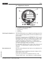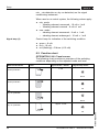
1
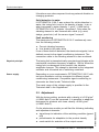
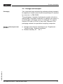
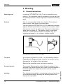
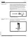
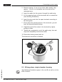
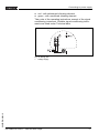
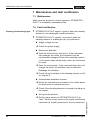
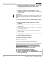
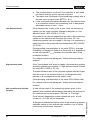
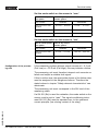
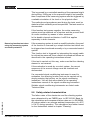
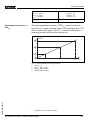
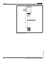
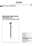
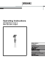
Connecting to power supply
Housing overview
4
4
1
Fig.
1
2
3
4
4
2
3
8: Material versions, single chamber housing
Plastic (not with EEx d)
Aluminium
Stainless steel (not with EEx d)
Filter element for pressure compensation (not with EEx d)
Electronics and connection
compartment
1
5
2
4
3
Fig.
1
2
3
4
5
Wiring plan
9: Electronics and connection compartment
Potentiometer for switching point adaptation (covered)
DIL switch for mode adjustment
Ground terminal
Terminals
Control lamp
For connection to a signal conditioning instrument. The sensor
is powered via the connected signal conditioning instrument.
For further information see the Technical data in the Supplement.
If the mode switch of OPTISWITCH 3100 C is correctly set to
"max", then the signal lamp on OPTISWITCH 3100 C lights
16
OPTISWITCH 3100 C - with two-wire output
29955-EN-060112
The wiring example is applicable for all suitable signal
conditioning instruments.