1
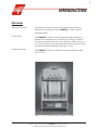
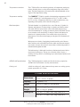
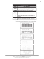
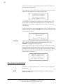
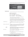
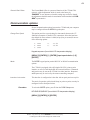
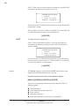
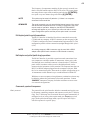
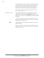
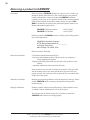
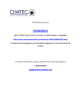
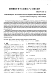
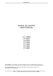
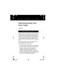
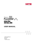
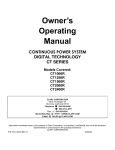
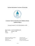
i CONTENTS 1 INTRODUCTION 1 Overview ............................................................................................................................ 1 Safety features .................................................................................................................... 3 Operator Safety ................................................................................................................. 3 2 UNPACKING AND ASSEMBLY 5 Assembly procedure ........................................................................................................... 6 Glass jar installation ........................................................................................................... 6 Inserting viscometer tubes/thermometers ........................................................................... 9 Filling the bath .................................................................................................................. 10 Draining the Bath ............................................................................................................. 11 3 BATH OPERATION 13 Applying power ................................................................................................................ 13 Cold Start .............................................................................................................. 13 Warm Start ............................................................................................................ 14 Self-test sequence ............................................................................................................. 14 Front panel operations ...................................................................................................... 16 Using the keypad .................................................................................................. 17 Setting bath temperature ................................................................................................... 18 Calibrating the CT-2000 ................................................................................................... 18 MENU options .................................................................................................................. 20 Change to (C/F) .................................................................................................... 20 Bath temperature offsets ....................................................................................... 20 Communication options .................................................................................................... 21 Full duplex (point-to-point) connections .............................................................. 23 Half duplex and polled (multi-drop) operations ................................................... 23 Commands, queries & responses .......................................................................... 23 CANNON® CT-2000 Constant Temperature Bath Revision 1.0g—February, 2012; CANNON® Instrument Company 2139 High Tech Road • State College, PA 16803 • USA ii A APPENDIX A — MODEL CT-2000 PROBLEM ANALYSIS B APPENDIX B — CORRECTING SHAFT & IMPELLER MISALIGNMENT 31 29 Shaft run-out correction .................................................................................................... 31 C APPENDIX C — CHOOSING A TEMPERATURE BATH LIQUID D APPENDIX D — CT-2000 SPARE PARTS LIST E APPENDIX E — WARRANTY/RETURN INFORMATION 33 35 37 Products limited warranty................................................................................................. 37 Reagent and chemical warranty........................................................................................ 37 Returning a product to CANNON® .................................................................................. 38 CANNON® CT-2000 Constant Temperature Bath Revision 1.0g—February, 2012; CANNON® Instrument Company 2139 High Tech Road • State College, PA 16803 • USA 1 CHAPTER 1 INTRODUCTION Overview Scope of the manual This manual is intended to provide information on the installation, characteristics and operation of the CANNON® CT-2000 Constant Temperature Bath. The CT-2000 The CANNON® CT-2000 Constant Temperature Bath is designed to maintain precise temperatures at a wide range of settings for accurate viscosity measurements. Because of its temperature stability and ease of use, it is also suitable for any other application where temperatures must be maintained within hundredths of one degree Celsius. Temperature range The CANNON ® CT-2000 is designed to maintain temperatures from 10°C to 150°C. Figure 1: The CT-2000 Constant Temperature Bath CANNON® CT-2000 Constant Temperature Bath Revision 1.0g—February, 2012; CANNON® Instrument Company 2139 High Tech Road • State College, PA 16803 • USA 2 Temperature selection The CT-2000 offers convenient keypad entry of temperature settings up to three decimal places over the entire temperature range of the instrument. The bath temperature will remain stable within hundredths of one degree of the temperature setting. Temperature stability The CANNON® CT-2000 is capable of maintaining temperatures of 10°C to 100°C within 0.01°C and temperatures of 101°C to 150°C within 0.03°C or closer. (Temperature stability at or below ambient may vary depending on the quality of the external cooling unit.) Bath description The bath chamber is a cylindrical clear vessel 300 mm (12 inches) in diameter and 300 mm (12 inches) high. A stainless steel baffle coated with white PTFE is located in the center of the bath and provides a convenient backdrop for viewing viscometers placed in the bath. The top cover contains seven round holes 51 mm (two inches) in diameter for insertion of viscometer holders. Two smaller holes are provided for thermometers. Twin fluorescent lamps provide glare-free illumination of the bath. Microprocessor circuitry, functioning in tandem with a pair of heaters and a stainless steel-encased RTD provides stable and accurate temperature control. A motor-driven stirrer ensures that a uniform temperature is maintained throughout the bath. The bath housing is fabricated from heavy aluminum and coated with a corrosion-resistant epoxy. The top cover consists of three layers; a stainless steel top surface, an insulating layer, and a bottom stainless steel heat reflector. ASTM D 445 specifications The CT-2000 temperature control provides the accuracy required by ASTM D 445 for kinematic viscosity measurements. Cooling coil A built-in cooling coil, when connected to tap water or a cooling system, permits operation to 10° Celsius. CT-2000 SPECIFICATIONS Dimensions 438 mm wide x 464 mm deep x 584 mm high (17.25 x 18.25 x 23 inches) Capacity 4.5 gallons (17 L) Weight 46 kg (101 pounds) (w/out bath fluid) Shipping Weight BOX 1: 46 kg (102 pounds) BOX 2: 14 kg (31 pounds) Catalogue # 9726- A30 CT- 2000 Const. Temp. Bath 120V 9726- A35 CT- 2000 Const. Temp. Bath 240V CANNON® CT-2000 Constant Temperature Bath Revision 1.0g—February, 2012; CANNON® Instrument Company 2139 High Tech Road • State College, PA 16803 • USA 3 Safety features Overheat thermistor A thermistor in the bath senses any over-temperature fault condition. If such a condition occurs, all power is removed from the bath heaters until an operator resets the over-temperature limit circuit. RTD cutoff detection If the control RTD is disconnected, all power to the bath heaters is cut off. Liquid-level sensor Operation of the bath is not possible unless it is filled with liquid to a safe operating level. A liquid-level sensor prevents the control circuit from heating the bath until the safe operating level is attained. The bath heaters are automatically turned off if the bath liquid drops below the minimum safe level. Operator Safety All technicians who use the CT-2000 should follow these basic safety procedures: Use appropriate safety precautions for working with high-temperature liquids/equipment. Follow instructions in this manual regarding use and maintenance of the CT-2000. Do not place the CT-2000 system on an unstable cart or stand. The CT-2000 should be placed on a stable laboratory table or bench. If any liquids are spilled into the electronic components of the CT2000, remove power from the unit and contact CANNON® Instrument Company immediately. Do not position power cords so that they are likely to be walked on or pinched by items placed on or against them. Keep all connections as neat as possible. If the CT-2000 will not be used for an extended period of time, unplug the power cord from the wall outlet. To disconnect the power cord, pull it out by the plug. Never pull the cord itself. CAUTION Do not attempt to service the CT-2000 system beyond the basic installation and troubleshooting guides provided with this manual. Contact CANNON® Instrument Company regarding service and repair needs. CAUTION The bath fluid used with the CT-2000 may be dangerous. Use the proper safety precautions when handling the bath fluid in use (refer to the Material Safety Data Sheet included with the bath fluid for more detail.) CANNON® CT-2000 Constant Temperature Bath Revision 1.0g—February, 2012; CANNON® Instrument Company 2139 High Tech Road • State College, PA 16803 • USA 4 This page intentionally left blank. CANNON® CT-2000 Constant Temperature Bath Revision 1.0g—February, 2012; CANNON® Instrument Company 2139 High Tech Road • State College, PA 16803 • USA 5 CHAPTER 2 UNPACKING AND ASSEMBLY This chapter of the manual provides assistance in unpacking and assembling the CT-2000 Constant Temperature Bath. Unpacking the CT-2000 1. Remove all components from the shipping container(s). 2. Remove any and all packing materials (Styrofoam, etc.) from the components. 3. Verify reception of shipped materials by comparing equipment items with packing/parts list(s). Report missing items to CANNON® Instrument Company immediately. 4. Inspect each component for signs of damage. Report damages to the shipper and to the CANNON® Instrument Company immediately. Damaged items Retain all packing materials until the instrument is connected and functioning properly. If any component(s) must be returned to CANNON® Instrument Company, the damaged item(s) should be packaged in the original shipping container. Refer to APPENDIX E of this manual for instructions on returning defective equipment. Customers outside the United States should contact the local CANNON® agent for procedures on returning products to CANNON® . The CANNON® CT-2000 Constant Temperature Bath is shipped in several boxes containing the following: bath housing, including the electronics drawer motor and stirrer, including the impeller and mounting plate glass bath jar Allen wrench front glass panel pieces (2) seven hole covers jar gasket top and bottom rubber thermometer holder instruction manual The bath unit housing is shipped completely assembled. However, the glass jar, the glass panels, and the motor and stirrer must be installed. To allow this, some disassembly of the bath unit housing is required. The tools required are a utility knife, Phillips screwdriver, and a 1/8" Allen wrench. The Allen wrench is included with the bath. CANNON® CT-2000 Constant Temperature Bath Revision 1.0g—February, 2012; CANNON® Instrument Company 2139 High Tech Road • State College, PA 16803 • USA 6 Assembly procedure 1. Unpack the bath unit housing and move it to its permanent location on a stable laboratory bench or table. 2. Remove all eight screws from the stainless steel top covers (see Figure 2). 3. Disconnect all external cabling (probes, heaters, and float switch) from the upper rear panel of the CT-2000. Figure 2: Detaching top cover 4. Remove the front top cover and rear top cover (see Figures 3 and 4). Use caution when removing the rear top cover because the temperature control probes and heating elements are attached to it. Figure 3: Removing front top cover Figure 4: Removing back top cover Glass jar installation 1. Remove the glass jar from its box. WARNING The glass jar is heavy. Use caution when lifting it. 2. Make sure the rubber support ring is seated properly around the bottom jar opening in the bath unit (see Figure 5). 3. Place the rubber gasket around the top rim of the jar (see Figure 6). The Figure 5: Seating the support ring CANNON® CT-2000 Constant Temperature Bath Revision 1.0g—February, 2012; CANNON® Instrument Company 2139 High Tech Road • State College, PA 16803 • USA 7 rubber may have to be trimmed slightly to allow the ends of the rubber gasket to meet with no gap when placed around the rim. 4. Remove the large piece of foam packing from the inside of the cabinet. Also remove the small piece of foam from the float level, located on the upper left-hand corner of the inside of the cabinet. 5. Lower the glass jar into the cabinet so it seats evenly on the rubber support ring. Figure 6: Seating the gasket 6. Unwrap the two glass panels. Place the thinner of the two pieces of glass in the slot closest to the jar (see Figure 7). 7. Place the wider (tempered) piece of glass in the front slot furthest away from the jar. The middle slot is left empty as a vapor barrier. 8. Replace the rear top cover. Align the four holes, then insert and tighten the screws. Figure 7: Placing inner glass panel 9. Replace the front top cover. Line up the four holes, then insert and tighten the screws. 10. To ensure that the gasket forms a tight seal with the top covers of the bath, proceed as follows: 11. Loosen the IEC lock screw securing the AC power cord to the rear panel of the electronics drawer. Then unplug all three cables (AC power, rectangular Cinch connector and round Amp connector) from the rear of the electronics drawer. 12. Pull out the electronics drawer using the handles provided on the front of the unit. Press down or pull up on the plastic release bars on either side of the drawer track to release the drawer, then pull the drawer completely free of the unit and set it aside. 13. When the drawer is removed, locate the four ¼-20 set screws visible at the top of the drawer opening underneath the bath. CANNON® CT-2000 Constant Temperature Bath Revision 1.0g—February, 2012; CANNON® Instrument Company 2139 High Tech Road • State College, PA 16803 • USA 8 14. Turn the set screws clockwise with the Allen wrench (included with the bath) until the top of the jar forms a tight seal with the covers. Make sure you tighten the set screws uniformly so the jar remains level. 15. Run the AC cord through the rear panel opening. 16. Replace the drawer in the slide tracks and push the drawer back into its opening. Insert the two power plugs into the rear of the drawer assembly. Motor-stirrer Complete the assembly of the bath by inserting the motor-stirrer per the instructions below: 1. Take the motor/stirrer from its box. Remove the two screws on the top heater housing and lift off the housing (see Figure 8). 2. Check the motor-stirrer impeller blades to make sure that the flat sections all lie in the same plane (see APPENDIX B), then insert the motor stirrer into the opening provided (see Figure 9). NOTE To avoid accidental bending of the motor shaft, do not hold the motor assembly by the shaft. Use care when inserting the motor shaft and impeller to prevent damage to delicate components. Two screws located on either side of the opening for the motor stirrer serve as locating pins for the motor support pad. Do not remove these screws; the holes in the pad fit loosely over their heads. The motor line cord should point toward the rear of the bath (offset slightly to the right or left). The motor stirrer should now lie flat on the top of the bath. Figure 8: Removing heater housing Figure 9: Installing motor-stirrer 3. Connect all plugs and probes to the correspondingly labeled sockets at the rear of the CT-2000 bath unit as follows (see Figure 10): CANNON® CT-2000 Constant Temperature Bath Revision 1.0g—February, 2012; CANNON® Instrument Company 2139 High Tech Road • State College, PA 16803 • USA 9 Figure 10: CT-2000 electrical connections PREHEAT cable to PREHEAT socket CONTROL HEATER cable to CONTROL HEATER socket FAN cable to FAN socket MOTOR STIRRER cable to MOTOR socket CONTROL PROBE cable to CONTROL PROBE socket OVER TEMP cable to OVER TEMP socket LEVEL FLOAT CABLE to LEVEL FLOAT socket 4. Reattach the top heater housing, making sure that the heater, motor, and fan cords pass through the left-hand opening (as viewed from the rear) and that the control probe, over-temperature probe, and level switch cords exit from the right opening (as viewed from the rear). The back lip on the rear top cover fits into the slot on the top heater housing. Line up the holes, insert screws, and tighten. 5. Adjust the four feet on the bottom of the bath housing to level the bath jar. This should be done prior to filling the bath with fluid. 6. Plug the CT-2000 main power cord at the back of the electronics drawer into an outlet with electrical specifications matching the label on the rear of the instrument. Inserting viscometer tubes/thermometers The top cover of the CT-2000 contains seven apertures, 51 mm (2") in diameter, for the insertion of viscometer tube holders. Two additional holes are provided for insertion of thermometers. Inserting viscometer tubes Remove the viscometer tube cover(s) from the top of the bath and carefully place the viscometer tube(s), with the proper holder attached, into the bath through the aperture(s) in the top cover. The viscometer tube should be inserted to a depth which ensures that the liquid under test and/ or any timing marks are a minimum of 6 mm (¼") below the top level of the liquid. CANNON® CT-2000 Constant Temperature Bath Revision 1.0g—February, 2012; CANNON® Instrument Company 2139 High Tech Road • State College, PA 16803 • USA 10 Thermometer immersion Proper thermometer immersion is critical for viscosity measurements. Even a calibrated thermometer will read incorrectly if is it improperly immersed in the bath. “Total immersion” kinematic viscosity thermometers should be used with the bulb and only the mercury column beneath the surface of the liquid, but with the emergent stem above the surface at ambient temperatures. Filling the bath CAUTION Make sure that the bath is placed in its intended final position before adding bath fluid. The CT-2000 should not be moved with bath fluid in the bath jar. NEVER USE FLAMMABLE BATH LIQUIDS. 1. Make sure that the instrument power is OFF and select a bath liquid appropriate to your operating temperature range (see APPENDIX C). Figure 11: Filling the bath 2. Fill the jar with bath liquid at ambient temperature to a level sufficient to engage the float switch. This float permits bath operation when the minimum amount of fluid has been added to the bath jar. 3. Continue to add fluid until the bath liquid level has risen to approximately 40 mm (1.5") of the top of the jar. 4. Turn the instrument power ON and incrementally heat the bath to desired control temperature while monitoring the bath liquid level carefully. The bath level must be 15-20 mm (approximately ½" to ¾") from the top of the jar at the control temperature. If it becomes apparent that this liquid level will not be achieved, return the bath to within 10°C of ambient, turn the instrument power OFF and add or remove liquid as necessary. 5. Repeat step four until you have attained the proper bath liquid level at the desired control temperature. CAUTION Different bath fluids expand at different rates. Do not overfill the bath! WARNING Monitor the level of bath liquid closely when operating the CT-2000 at higher temperatures (100-150°C). The bath liquid will expand as the temperature increases. The CT-2000 bath jar is not designed to contain liquid under pressure. If the bath is overfilled, liquid may overflow. CANNON® CT-2000 Constant Temperature Bath Revision 1.0g—February, 2012; CANNON® Instrument Company 2139 High Tech Road • State College, PA 16803 • USA 11 Draining the Bath If it becomes necessary to drain the liquid from the bath: Obtain a suitable container to hold all of the liquid drained from the bath (approximately 20-22 liters or 4.5 - 5 gallons). Make sure that the bath liquid is within 10°C of ambient temperature. Then insert a tube into the bath chamber from the top opening and siphon the liquid from the bath into a container positioned lower than the bath. WARNING Always use a rubber bulb or similar device to apply suction to a tube containing bath liquids. CANNON® CT-2000 Constant Temperature Bath Revision 1.0g—February, 2012; CANNON® Instrument Company 2139 High Tech Road • State College, PA 16803 • USA 12 This page intentionally left blank. CANNON® CT-2000 Constant Temperature Bath Revision 1.0g—February, 2012; CANNON® Instrument Company 2139 High Tech Road • State College, PA 16803 • USA 13 CHAPTER BATH OPERATION 3 NOTE Different thermometers have different installation requirements. Refer to the information included with the thermometer in use for specific installation instructions. Applying power Caution Do not power up the CT-2000 without completing the installation requirements. Make sure that the mains voltage specified on the rear identification label matches your mains voltage. NOTE The CT-2000 stores the “last-used” temperature setting in memory, so that on power-up the bath will attempt to adjust to the last known and entered temperature. Cold Start The Cold Start is the normal start-up mode for the CT-2000. During the Cold Start process, the CT-2000 will perform several diagnostics (see Self-Test Sequence, next page). At the conclusion of a successful test procedure, the results will be briefly displayed on the LCD screen. The bath heaters will be activated and the Bath Unit will begin controlling temperature according to the most recent temperature input. The current bath temperature and the target bath temperature will be visible on the liquid crystal display (LCD): CANNON® CT-2000 Constant Temperature Bath Revision 1.0g—February, 2012; CANNON® Instrument Company 2139 High Tech Road • State College, PA 16803 • USA 14 TEMPERATURE Actual Target 20.003 C 100.000 C HEATING To Cold Start the CT-2000, toggle the power BATH switch up. The POWER lamp should light when bath power has been activated. The five LED’s in the lower row of keys will blink on and then off, and the instrument will emit a short “beep” tone. Bath lighting To activate Bath Unit fluorescent lights, toggle the LIGHTS switch up. The switch lamp indicator will light when power is supplied to the fluorescent lights. Warm Start The Warm Start is the abnormal start-up mode for the bath and it occurs only if the power was previously off for a period less than about two seconds, or if a fault was detected in the microprocessor during the selftest sequence (see below). If the CT-2000 Process Function Monitor senses a momentary or ongoing failure in the system hardware or software, the heating elements will be shut down and the system will be reactivated in Warm Start mode. The keypad lights will flash in a repeating pattern and the heater power will be disabled (heating LED will not light). The display will show the following: POWER UP Warm Start Consult User’s Guide If this condition is ever discovered, the BATH power switch should be turned off. After waiting at least five seconds, turn the BATH power switch to the ON position and wait for the display to indicate either a warm or cold start again. If the bath comes up in a cold start condition and starts its normal self-test sequence, it is possible that a momentary power interruption caused the warm start condition and no further action is required. If the bath continues to enter the warm start condition, the user should consult CANNON® Instrument Company for further assistance. Self-test sequence The CT-2000 start-up includes a self-test procedure encompassing key components of the system. These tests, which will be displayed on the LCD during start-up, are described in the following table: CANNON® CT-2000 Constant Temperature Bath Revision 1.0g—February, 2012; CANNON® Instrument Company 2139 High Tech Road • State College, PA 16803 • USA 15 CT-2000 Self-Test TEST: TEST PURPOSE: Display Verifies function of the liquid crystal display (LCD) screen. The user may visually check for bad segments on the display. 32K RAM Verifies normal operation of CT- 2000 system memory. Pulse Width Verifies function of the PWM. Modulator A/D Calibrates analog–digital converter and verifies function and consistency. Voltage Levels Verifies power supply voltage levels (positive and negative). The following sequence illustrates the LCD for a normal self-test: Testing Display Testing 32k RAM ... Test Passed Testing Pulse Width Modulator..... Test Passed Testing A/D ..... Calibrating ....OK Consistency ....OK Testing Voltage Levels ...... Positive Supply..OK Negative Supply..OK Diagnostic Report All tests PASSED Entering Normal Operation CANNON® CT-2000 Constant Temperature Bath Revision 1.0g—February, 2012; CANNON® Instrument Company 2139 High Tech Road • State College, PA 16803 • USA 16 If the self-test sequence is accomplished successfully, the CT-2000 will commence normal operations. If any component of the self-test fails, the following message will appear on the LCD, accompanied by an audible warning tone: Diagnostics Report Some Tests FAILED See Owner's Manual Press ENTER to go on The ENTER key will flash in a repeating pattern and the heating LED will not light (see Warm Start information, page 12). In the event of a FAILED test, turn off the CT-2000 power for at least five seconds and restart the unit. It may be possible to resume normal operation of the CT-2000 following a failed self-test by pressing the ENTER key. If you do so, the following LCD message will appear: Attempting Normal Operation Proceed with CAUTION CAUTION A failed self-test may result in flawed operation and damage to the CT2000. If the CT-2000 repeatedly fails the self-test sequence, call CANNON® to arrange for servicing the unit. Following the self-test, the CT-2000 will enter its normal display condition provided that the RTD temperature sensor is connected properly. If the RTD sensor is unplugged at any time, the LCD will display a warning and it will be necessary to reconnect the RTD before proceeding with normal CT-2000 operations. The RTD sensor has been disconnected. Please reconnect it to reset the Bath. Front panel operations Following a successful Cold Start, the CT-2000 is ready for instructions from the user. NOTE Please check bath fluid levels before using the CT-2000 menu commands (see page 10). CANNON® CT-2000 Constant Temperature Bath Revision 1.0g—February, 2012; CANNON® Instrument Company 2139 High Tech Road • State College, PA 16803 • USA 17 The front panel of the CT-2000 provides a Liquid Crystal Display (LCD) screen and a simple keypad interface (see Figure 12). .)21 Figure 12: The CT-2000 front panel Using the keypad The keypad on the front panel of the CT-2000 consists of fifteen keys: white numbers 0 through 9 a white decimal point (.) key a yellow SET TEMP (set temperature) key a yellow CAL TEMP (calibrate temperature) key a yellow MENU key an orange ENTER key The keys on the bottom row (non-numerical keys) may illuminate to assist the operator in selecting key entry options. Press the appropriate keypad choice(s) firmly to make your selections. The CT-2000 will signal reception of each keypad command with a short, high-pitched “beep”. A longer beep indicates a data entry error (unacceptable input), such as a temperature value outside the range of the unit. The ENTER button The ENTER button is the most-used feature on the CT-2000 keypad. You must confirm each menu choice and numeric input by pressing this button. Selecting/canceling options To access any of the primary keypad options (SET TEMP, CAL TEMP and MENU), press the appropriate keypad button once. If you make a data entry error and wish to cancel your input sequence, press the primary keypad option button again. NOTE Initial options If the keypad does not receive user input for five minutes after a primary option is selected, the instrument will return to the LCD temperature display screen without saving any changes. Only three keypad options are enabled when the Cold Start routine is begun—SET TEMP, CAL TEMP and MENU: SET TEMP allows user to type in the desired bath temperature setting. See details below. CAL TEMP allows user to recalibrate the temperature sensing mechanism. See Calibrating the CT-2000, page 17). CANNON® CT-2000 Constant Temperature Bath Revision 1.0g—February, 2012; CANNON® Instrument Company 2139 High Tech Road • State College, PA 16803 • USA 18 MENU allows user to change temperature scale (°F-°C), reset calibration offsets and change other system settings (See Menu options). Setting bath temperature SET TEMP To set the bath temperature, choose SET TEMP from the keypad after a successful Cold Start. The LCD will display a message requesting user input of the new target temperature. Use the numeral keys to input the new temperature. You may enter positive numbers from 10°C to 150°C (50°F. To 302°F.) to three decimal places. Press the ENTER key to save your data. The bath will attempt to control at the new temperature. You may reset the temperature at any time. Correcting data entry errors If you make an error while setting the temperature, press the SET TEMP key again to exit the data entry screen. Then repeat the SET TEMP procedure. Lower temperatures When the desired temperature setting is slightly above, or below ambient, coolant must be circulated through the cooling coil. Input/output connections for the coil are located on the upper portion of the rear panel. Coolant temperature should be lower than the desired CT-2000 control temperature. NOTE Extreme temperatures or variability in the temperature of the coolant liquid may adversely affect CT-2000 temperature control. NOTE If a temperature is entered which is outside of the operational temperature range of the CT-2000, you will receive a RANGE ERROR message on the LCD screen. To correct this error, press ENTER and follow the screen prompts to enter appropriate data. When the CT-2000 is controlling temperature within one tenth of a degree, the LCD will display a temperature graph in 5/100ths of a degree increments at the bottom of the LCD screen. A small “tick” mark above the graph will provide a visual cue to the exact temperature of the bath relative to the requested temperature. TEMPERATURE Actual Target 40.003 C 40.000 C I -.1 |....|....|....|....|+.1 CANNON® CT-2000 Constant Temperature Bath Revision 1.0g—February, 2012; CANNON® Instrument Company 2139 High Tech Road • State College, PA 16803 • USA 19 Calibrating the CT-2000 The CT-2000 can be calibrated to any temperature reference standard for any desired Celsius or Fahrenheit temperature. The controls for entering the target (desired) temperature and the calibration at this temperature are convenient and largely intuitive. The instrument stores calibration corrections for every temperature integer. Procedure Use the CAL TEMP keypad option to calibrate the CT-2000 to your ASTM thermometer for a given temperature. NOTE Before you calibrate, make sure that the bath has stabilized at the desired test temperature. 1. Set the CT-2000 to the desired test temperature. 2. When the CT-2000 indicates that the instrument is controlling at the desired temperature, place your thermometer in the bath and wait for the temperature reading to stabilize (at least 10 minutes). 3. To calibrate, press the CAL TEMP key and enter the thermometer reading up to three decimal places, subject to the following parameters: a. A decimal point MAY be included as an entry. b. The entered temperature must be within the operational temperature range of the bath. If not, a CALIBRATION ERROR will be displayed on the LCD. c. The entered actual temperature must not cause a correction in temperature greater than ± 2.5°C. NOTE If you make an error while entering a temperature, press the CAL TEMP key again to cancel the operation, exit the calibration screen and return to normal CT-2000 operation. 4. When you have completed data entry, press ENTER to store the calibration data. 5. A new calibration constant has been stored for that test temperature. 6. You may recalibrate for any test temperature at any time. Calibration theory The CT-2000 stores user calibration information in a “bin” corresponding to every temperature integer. This calibration adjustment value for the bin is effective at all temperature ranges within 0.5 degrees of the temperature integer. The CT-2000 combines user calibration input with readings obtained by the temperature probe and data from the general bath offset, a protected menu option, which is preset at the factory by CANNON® Instrument Company (see the MENU section for more information). CANNON® CT-2000 Constant Temperature Bath Revision 1.0g—February, 2012; CANNON® Instrument Company 2139 High Tech Road • State College, PA 16803 • USA 20 MENU options The MENU selection from the CT-2000 keypad permits the user to access three functions: Change to (C/F) Changes screen display to alternate temp. scale Bath Temp Offsets Globally adjusts calibration data COM Setup Sets computer communication options Change to (C/F) The Change to (Celsius or Fahrenheit) option is essentially a toggle between two temperature scales. If the instrument is currently displaying numeric data in degrees Celsius, selecting this option will change the scale to Fahrenheit, and vice versa. To switch from one unit of measure to another, press the MENU key, press 1 and press ENTER. KEYPAD SEQUENCE: [MENU] [1] [ENTER] Bath temperature offsets To select a Bath Temperature Offset function, first press the MENU key, then press 2, and press ENTER. KEYPAD SEQUENCE: [MENU] [2] [ENTER] The Bath Temperature Offset option, when selected, displays two submenus: Clear Bins Clears all user-input calibration data for individual bins Set Gen. Bath Offset Allows global calibration adjustment by CANNON® Clear bins In rare instances, it may be desirable to clear all temperature calibrations and recalibrate each offset. To accomplish this function, select Clear Bins, then press 1. The LCD will display a warning message ... ABOUT TO CLEAR ALL CALIB. CONSTANTS! ARE YOU SURE? ENTER-Yes MENU-No CAUTION The offset values, once cleared, cannot be restored. The instrument may require recalibration for all offsets to produce reliable data! To erase user calibration data for all integer bins, press the ENTER key. To escape the Clear Bins screen without altering user calibration data, press the MENU key. CANNON® CT-2000 Constant Temperature Bath Revision 1.0g—February, 2012; CANNON® Instrument Company 2139 High Tech Road • State College, PA 16803 • USA 21 General Bath Offset The General Bath Offset is a protected function of the CT-2000. This option is a global adjustment which is made at the factory by CANNON®. In rare instances when this setting may need to be altered, the adjustment should be made in consultation with an authorized CANNON® representative. Communication options Several communication options between the CT-2000 and your computer may be configured from the MENU keypad option. Change Port Speed This option provides a speed setting for data transfer between the CT2000 and a computer via the RS-232C connection. Select the baud rate (the default for most software is 9600) in bps (bits per second) from one of the following options: 1. 1200 2. 2400 3. 9600 4. 5. 19.2k 38.4k Keypad sequence (from initial LCD temperature display): [MENU] [3] [ENTER] [1] [ENTER] [input speed choice (1-5)] [ENTER] Mode The MODE keypad option permits RS-232C or RS-485 communication options. The CT-2000 is equipped with a full-duplex RS-232C point-to-point interface as well as a half-duplex RS-485 network interface. Commands and Queries may be sent to the CT-2000 via either interface. Responses and Reports may be received by the master controlling computer. Interface information This interface is configured as 8 data bits with no parity and one stop bit. The mode of operation, polled (multi-drop) or point-to-point, can only be configured via the front panel menu. Procedure To select the MODE option, press 2 from the COM Setup menu. KEYPAD SEQUENCE (from initial LCD temperature display): [MENU] [3] [ENTER] [2] [ENTER] CANNON® CT-2000 Constant Temperature Bath Revision 1.0g—February, 2012; CANNON® Instrument Company 2139 High Tech Road • State College, PA 16803 • USA 22 If the CT-2000 was previously configured to operate in a polled (RS-485) environment, the following will appear on the LCD: COMMUNICATION MODE 1. Polled 2. Point to Point (Reports Disabled):1 The last line on the LCD indicates that timed reports are disabled and the present mode is polled. In this example, to operate in a point-to-point (RS-232) environment with or without timed interval reports, you would then press: [2] [ENTER] NOTE To configure reports, see page 20. If the CT-2000 is configured to operate in a point-to-point (RS-232) environment, the following will appear on the LCD when the RS-232 option is enabled: COMMUNICATION MODE 1. Polled 2. Point to Point 3. Config Reports :2 he last line on the LCD indicates that timed reports may be utilized and the present mode is point-to-point (:2). In this example, to reset the bath to a polled environment, you would press: [1] [ENTER] Reports The Reports option is accessed from the MODE submenu and is only enabled when the Point-to-Point mode is selected. Keypad Sequence (from initial LCD temperature display): [MENU] [3] [ENTER] [2] [ENTER] [3] [ENTER] The report is a serial dump of information on the operation of the CT2000 and includes: instrument address unit of temperature measurement (C/F) a time reference target bath temperature actual bath temperature (as measured by the bath RTD) CANNON® CT-2000 Constant Temperature Bath Revision 1.0g—February, 2012; CANNON® Instrument Company 2139 High Tech Road • State College, PA 16803 • USA 23 The frequency of temperature sampling for the report (in seconds) can then be selected from the options on the LCD screen. The report parameters range from a report each second (keypad selection [2] [ENTER] ) to a report every two minutes (keypad selection [8] [ENTER] ). NOTE This option may be turned off (selection 1) if there is no computer connected via the serial line. REMINDER The serial connection can only provide time interval reports of the actual and desired bath temperatures if the CT-2000 is configured in the pointto-point mode of operation. Otherwise, the REPORTS DISABLED message will appear on your LCD and you will not be able to access report configuration options until the point-to-point mode is resumed. Full duplex (point-to-point) connections The RS-232 interface is furnished for a direct connection between the CT-2000 and one computer. A DB-25 connector on the rear panel of the CT-2000 is configured as Data Communication Equipment (DCE). This configuration permits a direct connection (straight through cable--pins 18, 20). NOTE An existing computer’s DB-9 connector may be used with a DB-25 adaptor cable (DB-25 male connector to DB-9 female connector). Half duplex and polled (multi-drop) operations The RS-485 interface is provided to permit network connections from one computer to a multiple number of instruments. A three-wire (with feed-through) screw terminal connector is located on the CT-2000 rear panel. A three-conductor cable (two wire shielded preferred) can be connected to the instrument via this terminal. The computer must have an RS-232 to RS-485 adaptor plugged into the computer serial port. With the 3-wire connection in place, the network is capable of supporting up to 16 instruments at cable distances up to a combined total of 4000 feet. With three or more occupants or long distances, termination resistors may be added to enhance the performance of network operations. Contact CANNON® Instrument Company for further assistance on more extensive network configurations. Commands, queries & responses Basic protocol The protocol for the serial interface includes commands and queries sent by the master controlling computer and responses sent by the CT-2000 in reply. The CT-2000 may also issue timed interval reports automatically if configured to do so in the point-to-point mode (see Reports, previous page). In the polled (multi-drop) mode, specific reports will only be issued in response to a specific query. CANNON® CT-2000 Constant Temperature Bath Revision 1.0g—February, 2012; CANNON® Instrument Company 2139 High Tech Road • State College, PA 16803 • USA 24 All Commands or Queries must be preceded by the forward slash (/) and the selected address (0-9 or A-F). Commands are identified with the letter C and Queries are identified with the letter Q; these identifiers follow the address and precede the command or query information. All Commands or Queries must end with a carriage return (R). For examples of CT-2000 command and query language, consult the tables on the following pages. Downloading firmware The CT-2000 is capable of receiving new operational instructions via either the RS-232 or RS-485 interface. If the CT-2000 firmware is updated, and a new release issued by CANNON® Instrument Company, a diskette will be sent to the user along with instructions on how to perform this upgrade. A “download” push button is located on the rear panel of the CT-2000. Pressing and holding this button for several seconds places the CT-2000 instrument in the “download” mode. NOTE If the download button is pushed inadvertently, it may be necessary to restart the CT-2000. When the CT-2000 is in the download mode, the front LCD panel will display the version number for the resident download hardware code and the operational firmware. CANNON® CT-2000 Constant Temperature Bath Revision 1.0g—February, 2012; CANNON® Instrument Company 2139 High Tech Road • State College, PA 16803 • USA 25 Command Type " $$" Possible Argument “&..&” Description of Action Taken by CT-2000 AD none Calibrates the 16 bit A to D converter. When done the response is AD_NO if the calibration failed, or ADYES if the calibration was successful. If the command is not recognizable, an ERR is returned. As an example, if this command was sent to a CT- 2000 with an address of 5: /5CAD The response might look like this -5CADYES RT none Runs a complete self- Test like the one that is run on power up. A response is returned immediately indicating receipt of command RTYES or else the command is not recognizable and a ERR is the response. As an example, if this command was sent to a CT- 2000 with an address of 6: /6CRT The response might look like this: -6CRTYES DC none Display all temperature in degrees Celsius on the LCD and in all reports. This command places the bath in the Celsius mode for all temperature references. A response is returned immediately indicating receipt of command DCYES or else the command is not recognizable and a ERR is the response. As an example, if this command was sent to a CT- 2000 with an address of 1: /1CDC The response might look like this: -1CDCYES DF none Display all temperature in degrees Fahrenheit on the LCD and in all reports. This command places the bath in the Fahrenheit mode for all temperature references. A response is returned immediately indicating receipt of command DFYES or else the command is not recognizable and a ERR is the response. As an example, if this command was sent to a CT- 2000 with an address of 2: /2CDF The response might look like this: -2CDFYES SR &&& Sets the Reporting interval to the value of half- seconds as defined by the three character argument &&& which is in HEXADECIMAL. Only arguments from 000 to FFF will be accepted where 000 turns all reports off and any other numbers permit reports to be issued on any half- second interval from .5 seconds up to 2,047.5 seconds (ONLY IF THE CT- 2000 IS IN THE POINT- TO- POINT MODE OF OPERATION). If the command is accepted, the instrument will return with a SRYES response and the new report interval will take effect. If an invalid hex field is seen, the response will be SR_NO, and anything else will result in a ERR as the response. As an example, if this command, requesting reports every one second interval, was sent to a CT- 2000 with an address of 3: /3CSR002 The response might look like this: -3CSRYES CANNON® CT-2000 Constant Temperature Bath Revision 1.0g—February, 2012; CANNON® Instrument Company 2139 High Tech Road • State College, PA 16803 • USA 26 Command Type " $$" Possible Argument “&..&” Description of Action Taken by CT-2000 ST +&&&.&&& Sets the target (desired) Temperature of the bath as defined by the argument +&&&.&&& which is in degrees Celsius or Fahrenheit as previously set. Only fixed point numbers will be accepted and they must be within the operating range of the bath. If the command is accepted, a STYES will be the response, otherwise a ERR will be returned. As an example, if this command was sent to a CT- 2000 with an address of 4: / 4 C S T + 0 8 0 . 0 0 0 The response might look like this: -4CSTYES CB C|F Clears all of the calibration offset Bins as defined by the argument in Celsius or Fahrenheit. This command is performed immediately and there is no response. This command is usually used prior to sending the SB type commands. But in all cases, it should eventually be ended with an EE type command. As an example, if this command was sent to a CT- 2000 with an address of 9: /9CCBC The response might look like this: -9CCBCYES SB C@@@±&.&&& F@@@±&.&&& Sets the calibration offset Bin for the specified whole degree temperature @@@ as defined for C or F with the offset as defined in degrees &.&&&. The Celsius or Fahrenheit bin must be defined along with a plus or minus for this whole degree. The value of the offset must be defined as plus or minus and can be defined to the thousandths of degrees with &.&&&. If the command is accepted, a SBYES will be the response, otherwise a ERR will be returned. After a series of these command types are issued, the EE type command should follow. As an example, if this command was sent to a CT- 2000 with an address of 3: /3CSBC040-0.123 The response might look like this: -3CSBYES EE none Copies the contents of volatile RAM to non- volatile EEprom memory. This command should be used to end any sequence of CB and SB type commands which update the contents of the bins. After the memory transfer has completed successfully, a EEYES will be sent. If the transfer fails, a EE_NO will be the response; otherwise a ERR will be issued. As an example, if this command was sent to a CT- 2000 with an address of 8: / 8 C E E The response might look like this: -8CEEYES CANNON® CT-2000 Constant Temperature Bath Revision 1.0g—February, 2012; CANNON® Instrument Company 2139 High Tech Road • State College, PA 16803 • USA 27 Query Possible Type Argument " $$" "&..& Description of Response given by CT-2000 TB CF Transmits all of the whole degree temperature Bins for either Celsius or Fahrenheit or else ERR is transmitted. This response has the bin number in the first five columns followed by two spaces, and then the sign (if any or space if none) and the offset. As an example, if the following query is sent to a CT- 2000 at address 9: /9QTBC This queries the Celsius bins. The following report will be received: 10C 0.000 11C +0.123 -----(continues in order with ...) 149C -0.456 150C -0.789 -9QTBYES (end of report identifier) As another example, if the following query is sent to a CT- 2000 at address 9: /9QTBF This queries the Fahrenheit bins. The following report will be received: 50F 0.000 51F +0.123 -----(continues in order with ...) 301F -0.456 302F -0.789 -9QTBYES (end of report identifier) TR none Transmits a Report of key bath parameters. This is a single line report with the network address being in the first column followed by one space and then a C or F to indicate what the temperature scale is followed by at least one space and then one or two digits to indicate hours, followed by a colon, two digits for minutes, a decimal, and two digits for seconds which is the time elapsed since the last affected temperature entry. This is followed by at least one space and then the desired temperature to the thousandths of degrees. This is followed by at least one space and then the actual temperature of the bath to the thousandths of degrees. As an example, if the following query is sent to a CT- 2000 operating in Celsius with a target temperature of 40 degrees and residing on the network at address 3: /3QTR This queries the temperature report. The following report will be received: 3 C 12:34.56 40.000 40.002 -3QTRYES end of report identifier MT none This queries the Machine Type and firmware version. A single line report is issued indicating the model and number designation of the instrument at this address along with the firmware revision level. As an example, if the following query is sent to a CT- 2000 at network address 7: /7QMT This queries the machine type. The following report will be received: -7QMTMTCT2000 FV01.01 CANNON® CT-2000 Constant Temperature Bath Revision 1.0g—February, 2012; CANNON® Instrument Company 2139 High Tech Road • State College, PA 16803 • USA 28 This page intentionally left blank. CANNON® CT-2000 Constant Temperature Bath Revision 1.0g—February, 2012; CANNON® Instrument Company 2139 High Tech Road • State College, PA 16803 • USA 29 CHAPTER APPENDIX A — MODEL CT2000 PROBLEM ANALYSIS A A successful CT-2000 self-test is an indicator that there are no detectable errors and checked components are functional . There are certain conditions, however, that cannot be verified by these automatic tests. These include: 1. 2. 3. 4. 5. Viscosity of the bath liquid. Temperature probe installation Motor-stirrer functionality Temperature probe functionality Heater operation Problems with the first three items listed above may cause incorrect temperature stability. If items 4-5 fail, the bath may be non-operational. Fault isolation For assistance in troubleshooting your CT-2000 consult the troubleshooting guide below. If you are unable to resolve the difficulty, call CANNON® Instrument Company for assistance. Problem Possible cause/solution Bath does not appear to have power. • Power cable not connected to outlet or rear of electrical drawer. Attach cables. • Power cord unplugged. Attach cord to appropriate outlet (see electrical requirements on CT-2000 rear panel). • Power out on mains. Restore power. Bath illumination not functioning. • Separate switch for LIGHT must be on. • Fluorescent lamps may be defective. Replace. • Lamps may be out of sockets. Tighten lamps. • Lamp ballast may be defective. Replace. • Ballast Power Supply may not be working properly. Replace. Bath liquid not agitated. • Stirring motor not functioning. Check connection of stirring motor on rear panel. Visually check for working motor by connecting to outlet with the proper voltage (see motor label for correct voltage). CANNON® CT-2000 Constant Temperature Bath Revision 1.0g—February, 2012; CANNON® Instrument Company 2139 High Tech Road • State College, PA 16803 • USA 30 Problem Possible cause/solution Bath does not heat. • Sensors not operational. Check connections for sensors on rear panel. • Temperature set lower than current bath temperature. Check temperature setting — it must be above existing bath temperature for heat to go on. • Bath fluid level may be too low. Add fluid per manual instructions. Bath control outside of specific limits. • Bath fluid viscosity may be too high (if the fluid is too viscous at the desired temperature the stirring will be inadequate, resulting in poor control). • Stirring motor or impeller may not be operating properly. Check stirring motor and impeller. • Faulty RTD probe. Remove control RTD probe plug and check resistance with an ohmmeter (approx. 100W at room temperature). Bath top surface temperature too high. • Defective fan. Check cooling fan on rear panel and in top assembly. Air bubbles in bath fluid. • Level of fluid may be too low. Add fluid per manual instructions. • Stirring impeller may be on shaft with the wrong orientation. See APPENDIX B. • Bath fluid may be too viscous for operation at this temperature. Replace with appropriate fluid. CANNON® CT-2000 Constant Temperature Bath Revision 1.0g—February, 2012; CANNON® Instrument Company 2139 High Tech Road • State College, PA 16803 • USA 31 CHAPTER B APPENDIX B — CORRECTING SHAFT & IMPELLER MISALIGNMENT Motor-stirrer units supplied by CANNON® Instrument Company are checked after assembly to ensure minimum run-out (deviation from concentric rotation) at the impeller end of the shaft. The following instructions are intended to assist those who may be experiencing excessive vibration in the motor-stirrer because of shaft run-out or misalignment of the impeller blades. Set Screw Alignment The motor shaft contains a flat area. The coupling should be oriented in such a way that the set screw is aligned with the flat. The stirrer shaft and motor shaft should be inserted to approximately the same length in the coupling. You can test for shaft run-out and impeller blade alignment by placing the motor on a soft surface with impeller facing up. Connect the motor to the appropriate AC power source and observe the impeller and shaft. If run-out is severe, the motor will vibrate and the shaft will flutter noticeably. The impeller will appear blurred if the impeller blades are not in the same plane. If necessary, adjust the impeller blades by bending the large horizontal sections of each of the four segments so that they lie in the same plane. Since these segments are easily bent, check alignment whenever the impeller is bumped, or if there is any suspicion that the blade segments may have become misaligned. Shaft run-out correction The following procedure is suggested to correct shaft run-out: 1. Remove the motor-stirrer from the CT-2000 bath. 2. Grasp the motor firmly with the left hand. CANNON® CT-2000 Constant Temperature Bath Revision 1.0g—February, 2012; CANNON® Instrument Company 2139 High Tech Road • State College, PA 16803 • USA 32 3. Touch the tip of a soft crayon (such as a glass marking pencil) momentarily to the side of the shaft near the impeller end while the motor is running. The mark produced by the crayon will be evident as a line part way around the shaft. 4. Unplug the motor, hold the motor tightly against the body, and grasp the shaft in the right hand. 5. Bend the shaft away from the line segment on the shaft. 6. Repeat the test procedure, marking the shaft at a location slightly removed from the first crayon mark. 7. If the mark appears at the same side of a shaft as the first mark and is about the same length, the bending was not great enough to alter the condition and should be repeated with more force applied. If the mark has shifted to the opposite side, the force was too great and the shaft must be bent back with less force to correct the situation. This is a trial-and-error process which usually must be repeated several times. When the crayon makes a line at least two-thirds of the way around the shaft, the run-out has diminished to an acceptable level. A uniform line completely around the shaft would indicate no run-out detectable by this procedure. CANNON® CT-2000 Constant Temperature Bath Revision 1.0g—February, 2012; CANNON® Instrument Company 2139 High Tech Road • State College, PA 16803 • USA 33 CHAPTER C APPENDIX C — CHOOSING A TEMPERATURE BATH LIQUID The ideal bath liquid would possess low viscosity, high heat capacity, and low vapor pressure over a wide range of temperatures. In addition, the liquid should have a very high flash point and be relatively low in cost. If the fluid is to be used in a kinematic viscosity bath where it is necessary to view the instruments through the bath liquid, then it is important for the liquid to be clear and without color. Unfortunately, no single fluid meets all these requirements. When selecting a fluid, keep the following guidelines in mind. THE IDEAL BATH LIQUID Viscosity Should be low so that moderate stirring can effectively eliminate temperature gradients in the bath. H eat Capacity Temperature changes in the bath are less rapid with a high heat capacity. With the exception of water, most choices for bath fluids will have about the same heat capacity. Volatility A liquid with a low vapor pressure will require more frequent replenishment. Furthermore, rapid evaporation at the bath surface produces a cooling effect, making control more difficult. Because no single fluid can be used at all possible bath temperatures, the choice of a suitable fluid must begin by establishing the temperature range over which the bath will be operated. The following is a list of operating temperature ranges and bath liquids suitable for use in these ranges: CT-2000 BATH FLUID OPTIONS (10°C to 150 °C) Temperature Range (°C) Suitable Bath Liquids 10°C to 20°C Isopropyl Alcohol, Low-Viscosity Silicones 10°C to 60°C Water, Low Viscosity Oils,Silicones (Dow 200 fluid, 1 cSt) 60°C to 135°C White Oils with oxidation inhibitor, IBF Oil, Silicones (Dow 200 fluid, 20 cSt) 135°C to150°C Silicones (Dow 200 fluid, 20 cSt) CANNON® CT-2000 Constant Temperature Bath Revision 1.0g—February, 2012; CANNON® Instrument Company 2139 High Tech Road • State College, PA 16803 • USA 34 IBF Bath Oil IBF Bath Oil contains an oxidation inhibitor which reduces tendency to darken at higher temperatures. Viscosity is 36 cSt at 40°C, 5.6 cSt at 100°C. This oil is available from CANNON® (catalogue # 9726-L20). Silicone fluids Silicone fluids are available in a wide range of viscosities and can be used over a wide range of temperatures. However, silicones are also relatively expensive liquids. Also, a bath containing silicones requires extra care when used for capillary viscometry. If silicones are introduced into a viscometer capillary, its calibration factor will be altered by a significant amount. Water Water is almost the ideal fluid in the temperature range in which it can be used. Because in some cases there is a tendency for algae formation, some degree of water treatment may be necessary. Water can be used at temperatures close to the boiling point, but water replenishment to offset evaporation becomes a nuisance and the hot vapor can make working above the bath uncomfortable. Also, it may be difficult to establish optimum control at elevated temperatures because of the rapid cooling resulting from surface evaporation. Refined white oils Refined white oils (paraffin oils) of relatively low viscosity can be used at temperatures above the level at which water becomes unsatisfactory. Because these oils will turn faintly yellow and continue to darken with prolonged exposure to heat, we recommend adding an oxidation inhibitor to retard discoloration. The addition of an inhibitor will prolong the useful life of the oil, but it will eventually become as dark as untreated oil. The search for more suitable bath oils is unending. Hydrogenated vegetable oils, coconut oil, synthetic oils, and certain chemical compounds have been used with some success at various temperatures. CANNON® CT-2000 Constant Temperature Bath Revision 1.0g—February, 2012; CANNON® Instrument Company 2139 High Tech Road • State College, PA 16803 • USA 35 CHAPTER D APPENDIX D — CT-2000 SPARE PARTS LIST Following is a list of parts for the CT-2000 which may be ordered from CANNON® Instrument Company. Part Number P20.1 P20.22 P22.26 P22.39 P22.40 P25.3190 P27.1260 P27.1300 P27.1310 P27.1320 P27.2280 P27.2330 P27.2331 P27.5110 P27.5250 P27.5260 P27.5270 P27.5271 P27.5290 P27.5291 P27.8037 P27.5410.1 P27.6100 P27.6101 P27.6121 P27.4120 P51.1432 P51.1433 P62.1338 Description PYREX JAR 12 X 12 THERMOMETER HOLDER (RUBBER) JAR TOP GASKET HOLE COVERS & THERM HOLDER SET JAR SUPPORT GASKET OVER-TEMP PROBE SOCKET LAMP FLUORESCENT LAMP LAMINATED SAFETY GLASS PLATE GLASS BALLAST SOLID STATE 15 AMP CIRCUIT BREAKER 120V 8 AMP CIRCUIT BREAKER 240V FRONT BATH COVER W/ROUND HOLES PTFE COATED BAFFLE, WHITE COOLING COIL (SS) HEATER 700W 120V HEATER 700W 240V HEATER 400W 120V HEATER 400W 240V CONTROL PROBE RTD 100 LEVEL SWITCH MOTOR STIRRER 120V MOTOR STIRRER 240V SILICONE SPONGE MOTOR SUPPORT PAD VENT SHROUD (optional) LIGHTED SWITCH ROCKER 120V LIGHTED SWITCH ROCKER 240V SOLID STATE RELAY 25A CANNON® CT-2000 Constant Temperature Bath Revision 1.0g—February, 2012; CANNON® Instrument Company 2139 High Tech Road • State College, PA 16803 • USA 36 This page intentionally left blank. CANNON® CT-2000 Constant Temperature Bath Revision 1.0g—February, 2012; CANNON® Instrument Company 2139 High Tech Road • State College, PA 16803 • USA 37 CHAPTER E APPENDIX E — WARRANTY/ RETURN INFORMATION Products limited warranty In addition to other manufacturers’ warrantees, CANNON® Instrument Company (“the Company”) warrants all products (other than reagents and chemicals) delivered to and retained by their original purchasers to be free from defect in material and workmanship for one year from the date of the Company’s invoice to the purchaser. For a period of one year from the date of such invoice, the Company will correct, either by repair or replacement at the Company’s sole election, any defect in material or workmanship (not including defects due to misuse, abuse, abnormal conditions or operation, accident or acts of God, or to service or modification of the product without prior authorization of the Company) without charge for parts and labor. The determination of whether any product has been subject to misuse or abuse will be made solely by the Company. The Company shall not be liable for any special, incidental, or consequential damages, or any damage to plant, personnel, equipment or products, directly or indirectly resulting from the use or misuse of any product. Representations and warranties made by any person, including dealers and representatives of the Company, which are inconsistent, in conflict with, or in excess of the terms of this warranty shall not be binding upon the Company unless placed in writing and approved by an officer of the Company. Reagent and chemical warranty CANNON® Instrument Company (“the Company”) warrants all reagents and chemicals sold by the Company and delivered to and retained by their original purchasers to conform to the weight, specifications and standards stated on the package. The Company will, at its sole option, either replace or refund the price (net of freight, handling charges and taxes), of any reagent or chemical sold by the Company which does not conform to such weight, specifications and standards upon the prompt return of the unused portion. Except for replacement or refund of the net price, the Company shall not be liable for any damages occurring as a consequence of the failure of any reagent or chemical sold by the Company to conform to the weight, specifications and standards stated on the package. CANNON® CT-2000 Constant Temperature Bath Revision 1.0g—February, 2012; CANNON® Instrument Company 2139 High Tech Road • State College, PA 16803 • USA 38 Returning a product to CANNON® Procedure Before returning a CANNON® product for repair or service, make every attempt to identify the problem. If, after careful checking, the problem remains unidentified or unsolved, telephone CANNON® Instrument Company (or the local service agent) to consult with a product specialist. If the specialist cannot recommend a simple solution or repair, CANNON® will authorize the return of the product through the issuance of a Return Authorization number (RA). CANNON® Telephone Number CANNON® Fax Number 814-353-8000 814-353-8007 Products returned to CANNON® must be carefully packed. Ship prepaid to the following address: CANNON Instrument Company ATTN: Return Authorization # __________ 2139 High Tech Road State College, PA 16803 USA Please include the following: Required information • The Return Authorization number (RA). • The name and telephone number of the person at your company to contact regarding the product. • Shipping and billing instructions for the return of the product to your location. • A detailed explanation of the reason for the return. If the product is not covered by warranty, the customer will be provided with an estimate of the repair costs and asked for approval before any repairs are made. The customer will be required to issue a purchase order for the cost of the repairs. Hazardous materials Stringent government regulations restrict the shipment of mercury. Please contact CANNON® before returning a product that could possibly contain mercury. Shipping notification Products returned without prior notification (by either telephone or fax), or without Cannon’s authorization, will not be accepted. The customer may be billed a testing fee if a product is returned to CANNON® and found to be working properly. CANNON® CT-2000 Constant Temperature Bath Revision 1.0g—February, 2012; CANNON® Instrument Company 2139 High Tech Road • State College, PA 16803 • USA