1
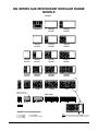
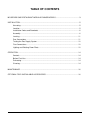
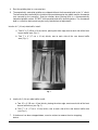
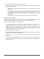
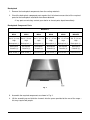
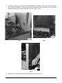
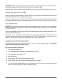
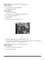
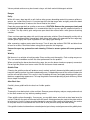
INSTALLATION &
OPERATION MANUAL
MG SERIES GAS RESTAURANT
MODULAR RANGE
MODEL
MG12
MG24
MG36
MG48
MG60
ML-52549
ML-52514
ML-52522
ML-52523
ML-52524
MODEL MG12
VULCAN-HART
COMPANY,
FORM 30832 Rev. E (Sept. 2000)
P.O.
BOX
696,
LOUISVILLE,
KY
40201-0696,
TEL. (502) 778-2791
IMPORTANT FOR YOUR SAFETY
THIS MANUAL HAS BEEN PREPARED FOR PERSONNEL QUALIFIED TO INSTALL GAS
EQUIPMENT, WHO SHOULD PERFORM THE INITIAL FIELD START-UP AND
ADJUSTMENTS OF THE EQUIPMENT COVERED BY THIS MANUAL.
POST IN A PROMINENT LOCATION THE INSTRUCTIONS TO BE FOLLOWED IN THE
EVENT THE SMELL OF GAS IS DETECTED. THIS INFORMATION CAN BE OBTAINED
FROM THE LOCAL GAS SUPPLIER.
IMPORTANT
IN THE EVENT A GAS ODOR IS DETECTED,
SHUT DOWN UNITS AT MAIN SHUT-OFF VALVE
AND CONTACT THE LOCAL GAS COMPANY
OR GAS SUPPLIER FOR SERVICE.
FOR YOUR SAFETY
DO NOT STORE OR USE GASOLINE OR OTHER
FLAMMABLE VAPORS OR LIQUIDS IN THE
VICINITY OF THIS OR ANY OTHER APPLIANCE.
WARNING
IMPROPER INSTALLATION, ADJUSTMENT,
ALTERATION, SERVICE OR MAINTENANCE
CAN CAUSE PROPERTY DAMAGE, INJURY OR
DEATH.
READ
THE
INSTALLATION,
OPERATING
AND
MAINTENANCE
INSTRUCTIONS THOROUGHLY BEFORE
INSTALLING OR SERVICING THIS EQUIPMENT.
IN THE EVENT OF A POWER FAILURE, DO NOT ATTEMPT TO OPERATE THIS DEVICE.
–2–
MG SERIES GAS RESTAURANT MODULAR RANGE
MODELS
TOP VIEWS
MG12
MG36ER
MG48Z
MG48ZT
MG60Z
MG60ZT
MG36X
MG36XT
MG48X
MG48XT
MG60X
MG60XT
MG24F
MG24FT
MG36F
MG36FT
MG48F
MG48FT
MG60F
MG60FT
MG24S
MG24ST
MG36S
MG36ST
MG48S
MG48ST
MG60S
MG60ST
MG36
MG48
MG60
MG24
Indicates step up
burner construction
FRONT VIEWS
MG12
MG24
MG36
MG48
MG60
PL-53565
MODEL SUFFIX DESIGNATIONS
S = 12" Griddle
F = 24" Griddle
X = 36" Griddle
NOTE:
RANGE MAY BE ORDERED WITH ONE 12" HOT TOP SECTION
IN PLACE OF TWO OPEN TOP BURNERS (FRONT TO REAR
ONLY)
Z = 48" Griddle
T = Thermostatic Control
–3–
TABLE OF CONTENTS
MG SERIES GAS RESTAURANT MODULAR RANGE MODELS ................................................... 3
INSTALLATION ................................................................................................................................... 5
Uncrating ................................................................................................................................. 5
Location ................................................................................................................................... 5
Installation Codes and Standards .......................................................................................... 6
Assembly ................................................................................................................................. 6
Leveling ................................................................................................................................. 11
Gas Connections ................................................................................................................... 11
Testing the Gas Supply System ........................................................................................... 12
Flue Connections .................................................................................................................. 12
Lighting and Shutting Down Pilots ....................................................................................... 12
OPERATION ..................................................................................................................................... 14
Controls ................................................................................................................................. 14
Before First Use .................................................................................................................... 14
Preheating ............................................................................................................................. 14
Cleaning ................................................................................................................................. 14
MAINTENANCE ................................................................................................................................ 16
OPTIONAL FIELD INSTALLABLE ACCESSORIES ....................................................................... 16
–4–
Installation, Operation and Care of
MG SERIES GAS RESTAURANT MODULAR RANGE
KEEP THIS MANUAL FOR FUTURE REFERENCE
Vulcan ranges are produced with quality workmanship and material. Proper installation, usage and
maintenance of your range will result in many years of satisfactory performance.
The manufacturer suggests that you thoroughly read this entire manual and carefully follow all of the
instructions provided.
INSTALLATION
UNCRATING
This range was inspected before leaving the factory. The transportation company assumes full
responsibility for safe delivery upon acceptance of the shipment. Immediately after unpacking, check
for possible shipping damage. If the range is found to be damaged, save the packaging material and
contact the carrier within 15 days of delivery.
Carefully uncrate range and place in a work-accessible area as near to its final installed position as
possible. Remove all shipping wire and wood blocking.
Before installing, verify that the type of gas supply (natural or propane) agrees with the specifications
on the rating plate located under the left-hand cooking top, mounted to the side wall of the range.
If the supply and equipment requirements do not agree, do not proceed with the installation. Contact
your dealer or Vulcan-Hart Company immediately.
LOCATION
CAUTION: The equipment area must be kept free and clear of combustible substances.
A standard 20,000 BTU burner input range must have a minimum clearance from combustible
construction of 6" (15 cm) at the sides and 6" (15 cm) at the rear.
A standard 26,000 BTU burner input range must have a minimum clearance from combustible
construction of 10" (25 cm) at the sides and 6" (15 cm) at the rear.
Step-up ranges using 20,000 or 26,000 BTU input burners must have a minimum clearance from
combustible construction of 10" (25 cm) at the sides and 6" (15 cm) at the rear.
The installation location must allow adequate clearances for servicing and proper operation.
The range must be installed so that the flow of combustion and ventilation air will not be obstructed.
Adequate clearance for air openings into the combustion chamber must be provided. Make sure there
is an adequate supply of air in the room to allow for combustion of the gas at the burners.
–5–
INSTALLATION CODES AND STANDARDS
For proper installation procedures in the United States of America, refer to:
1.
State and local codes.
2.
National Fuel Gas Code, ANSI-Z223.1 (latest edition). Copies may be obtained from The
American Gas Assn., Inc., 1515 Wilson Blvd., Arlington, VA 22209.
3.
National Electrical Code ANSI/NFPA-70 (latest edition). Copies may be obtained from The
National Fire Protection Assn., Batterymarch Park, Quincy, MA 02269.
In Canada, refer to:
1.
Local codes.
2.
CAN/CGA-B149.1 Installation for Natural Gas Burning Appliances and Equipment
(latest edition).
3.
CAN/CGA-B149.2 Propane Installation Code (latest edition), available from The Canadian
Standards Association, 178 Rexdale Blvd., Etobicoke, Ontario, Canada M9W 1R3.
ASSEMBLY
Installation of Standard Griddle Top Bricks
The griddle top section is extremely heavy. It will require three people to install the griddle and griddle
brick — two people to lift the griddle plate and one person to set the bricks and griddle thermostat
capillary bulb(s) in place.
The range griddle top section utilizes a two-fold baffle assembly to support the composite/mortar fire
bricks. There will always be only one small 61⁄2" (16 cm) wide baffle assembly with every griddle top
order. There will be at least one 97⁄8" (24 cm) wide baffle assembly per griddle, possibly more,
depending on the griddle width.
The 61⁄2" (16 cm) wide baffle will utilize two 10" x 4" (25 cm x 10 cm), and two 7" x 4" (17 cm x 10 cm)
brick sets.
The 97⁄8" (25 cm) wide baffle assembly will utilize two 10" x 4" (25 cm x 10 cm), and two 7" x 4"
(17 cm x 10 cm) brick sets.
1.
The griddle bricks are shipped in a rectangular cardboard box. Locate the box and carefully
inspect quantities as explained above.
NOTE: If a brick has been broken into two pieces, it can still be used. Just place the pieces into
position as shown in Fig. 1. However, if a brick is broken into more than two pieces, it will need
to be replaced. Contact your local Vulcan servicer.
2.
Clean anti-rust coating from top of griddle, following the procedures described in the
CLEANING - GRIDDLE PLATE section of this manual.
3.
Remove griddle plate. With one person at either side of the griddle, gently lift griddle straight up.
DO NOT pull griddle forward until the third person has checked to ensure that the capillary
bulb(s) (thermostatically controlled models only) are freed from the underside of the griddle plate.
If bulb(s) are still attached to the griddle, pull capillary bulb(s) wire gently through the “V” shield(s)
until the bulbs are free.
–6–
4.
Rest the griddle plate in a secure place.
5.
Thermostatically controlled griddles are shipped without the thermostat bulb in the “V” shield.
The bulb must be installed by the installer to prevent damage to the griddle and the thermostat
(not covered by the warranty). Exercise caution when placing brick in a thermostatically
controlled griddle section. DO NOT hit thermostat bulb while installing bricks. The thermostat
bulb is a sensitive device and may be easily knocked out of adjustment.
Into the 61⁄2" (16 cm) wide baffle, install:
a. Two 10" x 4" (25 cm x 10 cm) bricks, placing the miter edge, one to each side of the front
burner baffle area (Fig. 1).
b. Two 7" x 4" (17 cm x 10 cm) bricks, one to each side of the rear burner baffle
area (Fig. 1).
Fig. 1
6.
Into the 97⁄8" (24 cm) wide baffle, install:
a. Two 10" x 4" (25 cm x 10 cm) bricks, placing the miter edge, one to each side of the front
burner baffle area (see Fig. 1).
b. Two 7" x 4" (17 cm x 10 cm) bricks, one to each side of the rear burner baffle area
(see Fig. 1).
7.
If the burner has been strapped down, use wire cutters to remove the wire strapping
device.
–7–
8.
Check to ensure that all bricks and burners are secure.
9.
Carefully replace the griddle top section. Be sure that the griddle capillary and bulb(s) are not in
a position to be damaged.
a. Gently pull the griddle capillary toward the front of the range and out from under the
griddle area.
b. While two people (one to each side of the griddle) are lowering the griddle into place,
the third person must gently feed the griddle thermostat bulb(s) through the “V” shield(s)
until completely covered. Ensure that the capillary is not positioned over the burner
flame pattern.
c. Continue to lower the plate into place until it is resting evenly on top of the range.
Installation of Hot Top Bricks
The range hot top sections utilize composite/mortar fire bricks for heat distribution to the burners.
Install these bricks before connecting the gas supply line or installing the back riser.
There should be one box of bricks per hot top section.
1.
The composite/mortar bricks are shipped in a rectangular cardboard box. Locate the box and
carefully remove two 10" x 4" (25 cm x 10 cm), and two 7" x 4" (17 cm x 10 cm) bricks.
NOTE: If a brick has been broken into two pieces, it can still be used. Just place the pieces into
position as shown in Fig. 1. However, if a brick is broken into more than two pieces, it will need
to be replaced. Contact your local Vulcan servicer.
2.
Rest the hot top plate in a secure area.
3.
Install two 10" x 4" (25 cm x 10 cm) composite/mortar bricks, placing the miter edge, one to each
side of the front burner baffle area (see Fig.1).
4.
Install two 7" x 4" (17 cm x 10 cm) bricks, one to each side of the rear burner baffle area
(see Fig. 1).
5.
If the burner has been strapped down, use wire cutters to remove the wire strapping device.
6.
Check to ensure that all bricks and the burner are secure. Carefully replace the hot top section
on top of the range.
–8–
Backsplash
1.
Remove the backsplash components from the crating materials.
2.
Check the backsplash component parts against the list below to ensure that all the required
parts for the backsplash installation have been obtained.
• If any parts are missing, contact your dealer or closest parts depot immediately.
Backsplash Component Parts
MODELS
MG12
MG24
MG36
MG48
MG60
Std. 4" (10 cm)
Std. 4" (10 cm)
High
High
High
High
High
High
Backsplash (1)
Backsplash (1)
Backsplash (1)
Backsplash (1)
Backsplash (1)
Backsplash (1)
Backsplash
Backsplash
Backsplash
Backsplash
Backsplash
Backsplash
Channel (2)
Channel (2)
Channel (2)
Channel (2)
Channel (2)
Channel (2)
Heat Shield (1)
Heat Shield (1)
Heat Shield (1)
Heat Shield (1)
Heat Shield (1)
Heat Shield (1)
Std. 11" (27 cm) Std. 11" (27 cm) Std. 11" (27 cm)
MG36ER
Std. 5" (12 cm)
Fig. 2
3.
Assemble the required components as shown in Fig. 2.
4.
Lift the assembly up and slide the channels into the space provided at the rear of the range –
this may require two people.
–9–
5.
It may be necessary to pull the heat shield bottom out slightly in order to clear the flue box.
Be sure the backsplash is resting evenly and the channel holes are lining up with the holes
provided in the right- and left-hand body side (see Fig’s. 3 & 4).
PL-21424
Fig. 3
Fig. 4
PL-40045
PL-40045
Fig. 5
6.
Install six #10 sheet metal screws (3 to each channel leg) (Fig. 5).
– 10 –
LEVELING
Check the leveling of the range. Place a carpenter’s level across the range top plates. Level front to
back and side to side.
To adjust the leveling, tilt the range to one side and, using channel locks, unscrew the adjustable leg
insert as required. Repeat this procedure as necessary for each leg.
GAS CONNECTIONS
CAUTION: All gas supply connections and any pipe joint compound used must be resistant to
the action of propane gases.
Connect gas supply. Make sure the pipes are clean and free of obstuctions.
Codes require that a gas shutoff valve be installed in the gas line ahead of the range.
Standard ranges are equipped with fixed burner orifices which coincide with installation elevation.
Install the gas pressure regulator.
Before installing, ensure that regulator supplied agrees with rating plate gas supply.
The gas pressure regulator is NOT factory installed. The
regulator for this gas type is sealed within a plastic bag
and packaged with the range. This regulator must be field
installed by a qualified installer.
Natural gas regulators are preset for 4.0" W.C. (Water
Column); propane gas regulators for 10.0" W.C.
1.
Locate 3⁄4" (1.9 cm) gas connection pipe extending
from rear of range.
2.
Cover pipe threads with leak sealant.
3.
Screw regulator hand-tight onto pipe with
regulator arrow pointing towards range body
back (Fig. 6).
4.
Using pipe wrench, tighten regulator securely in
an upright position (Fig. 6).
Fig. 6
The arrow on the regulator shows the direction of the gas flow (Fig. 6). The pressure regulator must
be mounted horizontally to ensure proper preset outlet pressure. If the regulator is installed in any other
position, the outlet pressure must be reset for proper operation.
A leak limiter is supplied with every regulator to allow excess gas pressure to escape. Do not obstruct
leak limiter on gas pressure regulator, because obstruction may cause regulator to malfunction.
– 11 –
WARNING: PRIOR TO LIGHTING, CHECK ALL JOINTS IN THE GAS SUPPLY LINE FOR LEAKS.
USE SOAP AND WATER SOLUTION. DO NOT USE AN OPEN FLAME.
After piping has been checked for leaks, all piping receiving gas should be fully purged to remove air.
TESTING THE GAS SUPPLY SYSTEM
When gas supply pressure exceeds 1⁄2 psig (3.45 kPa), the range and its individual shutoff valve must
be disconnected from the gas supply piping system.
When gas supply pressure exceeds 1⁄2 psig (3.45 kPa) or less, the range should be isolated from the
gas supply system by closing its individual manual shutoff valve until the range is ready for start-up.
FLUE CONNECTIONS
DO NOT obstruct the flow of flue gases from the flue located on the rear of the range. It is recommended
that the flue gases be ventilated to the outside of the building through a ventilation system installed by
qualified personnel.
From the termination of the flue to the filters of the hood venting system, a minimum clearance of 18"
(45 cm) must be maintained.
Information on the construction and installation of ventilating hoods may be obtained from the
standard, “Vapor Removal from Cooking Equipment,” NFPA No. 96 (latest edition), available from The
National Fire Protection Association, Batterymarch Park, Quincy, MA 02269.
LIGHTING AND SHUTTING DOWN PILOTS
All adjustment procedures associated with initial start-up should be performed by an authorized
Vulcan-Hart installation or service person.
Hot Top and Griddle Top Burners
1.
Turn main gas supply ON.
2.
Turn all top burner valve knobs ON to purge gas line of air.
3.
Turn top burner valve knobs OFF.
4.
Wait 30 seconds.
5.
Using a taper, light the hot top or griddle top pilot.
6.
If pilot fails to light, wait 5 minutes and repeat Steps 1 through 5.
7.
Turn one hot top or griddle top burner valve ON to ensure that all gas lines are completely purged
of air. Turn burner valve OFF when gas begins to flow.
– 12 –
Nightly Shutdown: Turn burner valve OFF; pilot will remain lit.
Complete Shutdown
1.
Turn burner valve OFF; pilot will remain lit.
2.
Turn main gas supply OFF.
Open Top Burners
1.
Turn main gas supply ON.
2.
Turn all top burner valve knobs ON to purge gas line of air.
3.
Turn top burner valve knobs OFF.
4.
Wait 30 seconds.
5.
Using a taper, light the open top pilot (Fig. 7).
Fig. 7
6.
If pilot fails to light, wait 5 minutes and repeat Steps 1 thru 5.
7.
Turn one open top burner valve ON to ensure that all gas lines are completely
purged of air. Turn burner OFF when gas begins to flow.
Nightly Shutdown: Turn burner valve OFF; pilot will remain lit.
Complete Shutdown
1.
Turn burner valve OFF; pilot will remain lit.
2.
Turn main gas supply OFF.
– 13 –
OPERATION
WARNING: THE RANGE AND ITS PARTS ARE HOT. BE VERY CAREFUL WHEN OPERATING,
CLEANING OR SERVICING THE RANGE.
CONTROLS
OPEN TOP BURNER KNOB — Regulates gas flow to top burners. To increase heat, turn knob
counterclockwise; to decrease, turn knob clockwise.
HOT TOP OR GRIDDLE TOP BURNER KNOB — Regulates gas flow to the hot top or griddle top
burner. To increase heat, turn knob counterclockwise; to decrease, turn knob clockwise.
BEFORE FIRST USE
Griddle Seasoning
CAUTION: This griddle plate is steel, but the surface is relatively soft and can be scored or
dented by the careless use of a spatula or scraper. Be careful not to dent, scratch, or gouge the
plate surface. Do not try to knock off loose food that may be on the spatula by tapping the corner
edge of the spatula on the griddle surface.
A new griddle surface must be seasoned to do a good cooking job. The metal surface of the griddle
is porous. Food tends to get trapped in these pores and stick; therefore, it is important to “season” or
“fill up” these pores with cooking oil before cooking. Seasoning gives the surface a slick, hard finish
from which the food will release easily.
To season, heat griddle top section at a low burner setting. Pour one ounce of cooking oil per square
foot of surface over the griddle top section. With an insulated cloth, spread the oil over the entire griddle
surface to create a thin film. Wipe off any excess oil with an insulated cloth.
Repeat this procedure 2 to 3 times until the griddle has a slick surface.
PREHEATING
Hot Top and Griddle Top Burners
Turn burner “ON” to highest heat to heat hot top section quickly. Hot top or griddle top will be ready to
cook on in about 10 minutes. After top section has reached operation temperature, turn some of the
burners down. You will save as much as 80% of gas consumption and notice very little difference in
cooking performance as long as you have allowed the entire hot top or griddle top section to preheat
properly.
Open Top Burners
Open top burners ignite quickly and do not require any preheating time. When food comes to a rolling
boil, cut back to slower boil to conserve energy, yet continue boiling. Turn burners ON only when in
use.
CLEANING
Do not use Dawn® dish detergent to clean the exterior or interior components of the range.
Do not use scouring powder; it is extremely difficult to remove completely and can build up
accumulations that will damage the oven.
– 14 –
Vulcan painted surfaces may be cleaned using a soft cloth and mild detergent solution.
Ranges
Daily:
While still warm, wipe top with a soft cloth or other grease absorbing material to remove spillovers,
grease, etc., before they burn in. A crust on top of the hot top range looks unsightly and slows down
cooking speed because it reduces the flow of heat to the utensil.
Empty the grease pan daily or as often as necessary. CAUTION: Remove the grease pan slowly and
be careful of liquid wave action. It is recommended that the grease pan be emptied whenever it
is 3⁄4 filled. The drip shield, grids and grease pan should be washed with a mild grease-dissolving
solution.
Clean cast iron open top grates with a mild soap and water solution. Rinse thoroughly and dry with a
clean, water-absorbent towel. Immediately after drying (with grates still removed from the range top),
season grates lightly with liquid vegetable or Pam® spray-type cooking oil.
After seasoning, replace grates onto the range. Turn all open top sections ON LOW and allow them
to burn for at least 15 minutes before using pots or pans on the range top.
Season the open top grates after each cleaning. Failure to season grates will cause grates to
rust.
Weekly:
Boil burners in a solution of washing soda. Rinse and dry parts thoroughly. Flash rusting may occur.
This is a normal condition and will not affect performance or the product.
When reinstalling the burner back onto the range, be sure the burner heads are properly connected.
Do not light the pilot or turn burner valve ON with the burner head removed.
Griddle Plate
Cleaning the griddle section will produce evenly cooked, perfectly browned griddle products and will
keep the cooking surface free from carbonized grease. Carbonized grease on the surface hinders the
transfer of heat to the food. This results in loss of cooking efficiency and spotty browning which gives
foods an unappetizing appearance. To keep the griddle clean and operating at peak efficiency, follow
these simple instructions:
After Each Use:
Carefully clean griddle with wire brush or flexible spatula.
Daily:
Thoroughly clean backsplash, sides and front. Remove grease drip tray and pan, empty and wash out
in the same manner as any ordinary cooking utensil.
Clean griddle surface thoroughly. If necessary, use a griddle stone, wire brush or steel wool over the
surface. Rub with the grain of the metal while still warm. A detergent may be used on the plate surface
to help clean it, but the cleaner must be thoroughly removed. After removal of detergent, the surface
of the plate must be reseasoned with a thin film of oil to prevent rusting and food sticking.
If the griddle is to be shut down for an extended period, put a heavy coat of grease over the griddle plate.
– 15 –
MAINTENANCE
WARNING: THE RANGE AND ITS PARTS ARE HOT. BE VERY CAREFUL WHEN OPERATING,
CLEANING OR SERVICING THE RANGE.
VENT
When cool, check the flue vent every six months for obstructions.
SERVICE AND PARTS INFORMATION
To obtain service and parts information concerning this modular range, contact the Vulcan-Hart
Service Agency in your area (refer to listing supplied with the modular range), or Vulcan-Hart Service
Department at the address or phone number shown on the front cover of this manual.
OPTIONAL FIELD INSTALLABLE ACCESSORIES
OPTIONS
DESCRIPTION
Flue Devices
1. Stainless steel backsplash.
2. Stainless steel 11" (28 cm) low riser.
3. Stainless steel 4" (10 cm) low riser (use with open tops only).
Flex Hose
and Quick
Disconnects
1.
2.
3.
FORM 30832 Rev. E (Sept. 2000)
3
⁄4" (1.9 cm) flex hose/disconnect – 3 ft. (0.9 m) long.
⁄4" (1.9 cm) flex hose/disconnect – 4 ft. (1.2 m) long.
3
⁄4" (1.9 cm) flex hose/disconnect – 5 ft. (1.5 m) long.
3
– 16 –
PRINTED IN U.S.A.