1
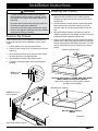
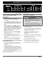
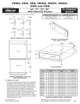
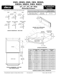
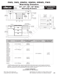
Installation Instructions
Warming Drawer
Models:
Part No. 102345 Rev. N
ERWD30, EWD24, EWD27, EWD30, EWD36, IWD24,
IWD27, IWD30, MRWD27, MRWD30, MWDH27,
MWDH30, MWDV27, MWDV30, OWD24, PWD27,
PWD30
All specifications are subject to change without notice. Dacor ® assumes no liability for changes to specifications.
© 2007 Dacor, all rights reserved.
Table of Contents
Before You Begin............................................................... 1
Important Safety Instructions........................................... 1
General Safety Precautions.............................................. 2
Installation Specifications................................................. 3
Verifying the Package Contents........................................ 3
Installation Planning.......................................................... 3
Install a Support Platform in the Cabinet.......................... 6
Electrical and Environmental Specifications..................... 6
Installation Instructions..................................................... 7
Remove the Drawer ......................................................... 7
Installing the Chassis........................................................ 7
Re-installing the Drawer.................................................... 8
Verifying the Warming Drawer Operation......................... 8
Installation Checklist......................................................... 8
Before You Begin...
Important:
Installer: In the interest of safety and to minimize problems, read these installation instructions completely and carefully
before you begin the installation process. Leave these installation instructions with the customer.
Customer: Keep these installation instructions for future reference and the local electrical inspector’s use.
If you have questions or problems with installation, contact
your Dacor dealer or the Dacor Customer Service Team.
For repairs to Dacor appliances under warranty call the
Dacor Distinctive Service line. Whenever you call, have
the complete model and serial number for your appliance
available. The numbers are found on the product data label
located on back of the drawer front.
The data label also contains the product electrical
requirements
Dacor Customer Service
Phone: (800) 793-0093 (U.S.A. and Canada)
Monday — Friday 6:00 a.m. to 5:00 p.m. Pacific Time
Web site:
www.Dacor.com
Dacor Distinctive Service (repairs under warranty only)
Phone: (877) 337-3226 (U.S.A. and Canada)
Monday — Friday 6:00 a.m. to 4:00 p.m. Pacific Time
Product data label
on back for drawer
front
Important Safety Instructions
Important Information About
Safety Instructions
•
•
The Important Safety Instructions and warnings in
these instructions are not meant to cover all possible
problems and conditions that can occur. Use common
sense and caution when installing, maintaining or
operating this or any other appliance.
Always contact the Dacor Customer Service Team
about problems and conditions that you don’t
understand.
Safety Symbols and Labels
DANGER
Immediate hazards that WILL result in severe personal
injury or death.
warning
Hazards or unsafe practices that COULD result in severe
personal injury or death.
caution
Hazards or unsafe practices that COULD result in minor
personal injury or property damage.
1
Important Safety Instructions
General Safety Precautions
To reduce risk of fire, electric shock, serious injury or death when using your appliance, follow basic precautions, including
the following:
warning
warning
•
•
Use this appliance only for its intended use as
described in this manual. Use it only to warm food
and heat plates and utensils. It is not designed for
commercial, industrial or laboratory use.
Only model OWD24 is approved for use in outdoor
installations and near water (bathrooms). Do not
use, store or install warming drawer models other
than OWD24 near water, for example, near sinks,
swimming pools or in a wet basement.
•
Model OWD24, when installed as a towel warmer,
must have the supplied wire rack installed in the
drawer bottom according to these instructions.
•
Do not install or operate a product that is
damaged, has a damaged power cord or plug,
or is malfunctioning in any manner. Return the
appliance to the nearest authorized service facility
for examination, repair or adjustment.
•
Make sure that the appliance has been properly
installed and grounded by a qualified installer
according to the accompanying installation
instructions. Have the installer show you the
location of the electrical outlet so that you know
where to disconnect power to the appliance.
•
Do not repair or replace any part of the warming
drawer unless specifically recommended in the
literature accompanying it. All other service should
be done by a qualified technician.
•
Use of accessory attachments not recommended by
the appliance manufacturer may cause injuries.
•
Before cleaning or performing any type of service,
make sure that the power plug is disconnected from
the electrical outlet and that the unit is cool.
•
•
DO NOT TOUCH ANY HOT SURFACES IN OR
ON THE WARMING DRAWER DURING OR
IMMEDIATELY AFTER USE. Use the handle
instead. After use, make sure these surfaces have
had sufficient time to cool before touching them.
Heating elements may be hot, even though they are
dark in color.
To avoid the possibility of fire or burns, do not allow
clothing, potholders, towels or rags to come into
contact with any part of the warming drawer during
and immediately after use. Do not wear loose or
hanging apparel while using the appliance.
•
Clean the warming drawer thoroughly before
operating it for the first time.
•
To reduce the risk of fire in the warming drawer, do
not overcook food. Do not leave it unattended with
paper, plastic or other combustible materials inside.
•
If materials inside the warming drawer should ignite,
keep the drawer closed and shut off the power at
the circuit breaker panel or fuse box.
•
Exercise caution when opening the warming drawer.
Let hot air or steam escape before looking or
reaching into the warming drawer.
•
Use only dry pot holders when removing food and
cookware from the warming drawer. Wet pot holders
can cause steam burns.
•
Do not put items like whole eggs, sealed containers
or closed glass jars in the drawer. They may
explode when heated, causing injury.
•
When the warming drawer is on in continuous
mode (∞), it will remain on until turned off manually.
Exercise caution when operating the unit in
continuous mode.
•
Do not place more than 50 pounds in the drawer.
•
Properly clean and maintain the unit regularly as
instructed in the use and care manual. Clean only
those parts listed, in the manner specified.
•
Do not use abrasive scrubbers or abrasive/caustic
cleaners or detergents on this appliance. They
may permanently damage the finishes. Do not use
aerosol cleaners, because they may be flammable
or cause corrosion of metal parts.
•
Make sure the warming drawer is used only by
those individuals who are able to operate it properly.
•
Do not tamper with the controls.
•
Never allow anyone, including children to sit, stand
or climb on any part of the appliance, including
the drawer. Doing so may cause tipping, damage,
serious injury or death.
•
Do not leave children unattended in the area around
the appliance. Do not allow children to operate it,
play with the controls, pull on the handle or touch
other parts. Do not store items of interest to children
above the warming drawer. Children could be
burned or injured while climbing on the appliance.
Read and save these instructions
2
Installation Specifications
Verifying the Package Contents
•
Use and care manual
•
Mounting screws
•
Wire rack with mounting hardware (OWD24 only)
C
B
Installation Planning
Chassis
•
A qualified technician must complete the installation of this builtin appliance. Proper installation is the customer's responsibility.
•
Carefully check the location where the drawer is to be installed.
The drawer should be placed for convenient access. Make
certain that electrical power can be provided in the selected
location. Install the warming drawer in wood cabinets only.
•
Plan the installation so that all minimum clearances are met or
exceeded. Dimensions shown provide minimum clearances,
unless otherwise noted. Be certain that proper clearance is
provided for the drawer door when it is in the open position.
•
The specified minimum cabinet depth and width must be
provided. The cabinet depth and width must completely enclose
the recessed portion of the drawer.
•
Cabinet cutout dimensions must be used as indicated. All
contact surfaces between the appliance and the cabinet must
be solid and level. The drawer support platform must be flush
with the bottom edge of the cabinet cutout.
•
5/16”
(8 mm)
Drawer open
A custom front panel is required for IWD
series models and optional for OWD24.
•
An optional Epicure® style front panel kit
is available for model OWD24.
**
F
Overall Dimensions - IWD/OWD Series
Top View
Make certain that you have everything necessary to ensure a
proper installation before proceeding.
•
E
40” (1016 mm)
3 prong
120 Vac power cord
Mounting hole,
9 places
**
**
**
G
D
Chassis without
drawer installed
A
** = OWD24 mounting holes
Drawer Face Dimensions
(IWD/OWD Series)
(B) Dimension
Chassis Width
(C) Dimension
Chassis Face
Width
IWD24
22 5/16” (567 mm) 22 1/4” (565 mm)
22 3/8” (568 mm)
IWD27
25 5/16” (643 mm) 25 1/4” (641 mm)
25 3/8” (645 mm)
IWD30
28 5/16” (719 mm) 28 1/4” (718 mm)
28 3/8” (721 mm)
OWD24
22 1/2” (571 mm)
22 1/2” (571 mm)
Model
(A) Dimension
Drawer Face
Width
Chassis Dimensions
(IWD/OWD Series)
22 1/2” (571 mm)
(D)
(E)
(F)
(G)
Dimension Dimension Dimension Dimension
Drawer
Chassis
Drawer
Chassis
Face Height
Depth
Depth
Height
8 15/16”
(227 mm)
23 3/8”
(594 mm)
23 13/16”
(605 mm)
9 1/16”
(230 mm)
11 7/8”
(302 mm)
20”
(508 mm)
18”
(457 mm)
11 7/8”
(302 mm)
See following page for chassis dimensions for other models
3
Installation Specifications
10 1/8”
(257 mm)
A
Drawer Face Dimensions
(MWDH series shown)
Model
(A) Drawer Face
Width
(B) Chassis Face
Width
(C) Chassis Width
ERWD30
30” (762 mm)
29 5/8” (752 mm)
28 1/4” (718 mm)
EWD24
24” (610 mm)
23 5/8” (600 mm)
22 1/4” (565 mm)
EWD27
27” (686 mm)
26 5/8” (676 mm)
25 1/4” (641 mm)
EWD30
30” (762 mm)
29 5/8” (752 mm)
28 1/4” (718 mm)
EWD36
36” (914 mm)
35 5/8” (905 mm)
34 1/4” (870 mm)
MRWD27
26 3/4” (679 mm)
26 5/8” (676 mm)
25 1/4” (641 mm)
MRWD30
29 3/4” (756 mm)
29 5/8” (752 mm)
28 1/4” (718 mm)
MWDH27
27” (686 mm)
26 5/8” (676 mm)
25 1/4” (641 mm)
MWDH30
30” (762 mm)
29 5/8” (752 mm)
28 1/4” (718 mm)
MWDV27
27” (686 mm)
26 5/8” (676 mm)
25 1/4” (641 mm)
MWDV30
30” (762 mm)
29 5/8” (752 mm)
28 1/4” (718 mm)
PWD27
27” (686 mm)
26 5/8” (676 mm)
25 1/4” (641 mm)
PWD30
30” (762 mm)
29 5/8” (752 mm)
28 1/4” (718 mm)
Warming Drawer Overall Dimensions
See page 3 for IWD and OWD series chassis dimensions
B
C
ERWD
3 1/2"
(89 mm)
Chassis
23 3/8"
(594 mm)
5/64"
(2mm)
Drawer open
23 13/16”
(605 mm)
EWD
3 7/16"
(87 mm)
1 1/8"
(29 mm)
1"
(25 mm)
MWDH/V
All other MRWD
series
3 1/4"
(83 mm)
1"
(25 mm)
1"
(25 mm)
MRWD30B
(only)
1 7/16"
(37 mm)
PWD
2 1/4"
(57 mm)
1"
(25 mm)
Handle Dimensions
40” (1016 mm)
Mounting
3
prong 120 Vac
hole 9 places
power cord
Overall Dimensions
Top View
(EWD series shown)
1/2" (13 mm)
10"
(254 mm)
Chassis without
drawer inserted
1/2" (13 mm)
Chassis Dimensions
4
9"
(229 mm)
Installation Specifications
Warming
drawer
36" Typ.
(914 mm)
Warming
drawer
Cooktop
C
D
120 Vac
electrical
outlet
A
B
3/4" Min.*
(19 mm)
27"/30"/36" Dacor
single wall oven
D
Warming
drawer
C
3/4" Min.*
(19 mm)
Warming
drawer
36" Typ.
(914 mm)
A
B
C
120 Vac
elect.
Toe kick
C
3/4" Min.*
(19 mm)
A
3/4” Min.*
(19 mm)
C
D
1 1/2" (38 mm)
Typical countertop
Warming
drawer
120 Vac
elect.
Cutouts Dimensions
NOTES:
120 Vac
electrical
outlet
•
Models EWD36, OWD24 and IWD series
models cannot be installed above or
below another warming drawer (any type).
•
Model OWD24 is not approved for
installation above, below or adjacent to a
wall oven or a warming drawer, including
the same model.
Model
(A) Cutout Width
(B) Min. Width to
Adjacent Doors/
Drawers
(C) Cutout Height
(D) Min. Vertical Gap
Between Cutouts
ERWD30
28 1/2” (724 mm)
30 1/4” (768 mm)*
9 1/8” (232 mm)
1 1/4” (32 mm)*
EWD24
22 1/2” (572 mm)
24 1/4” (616 mm)*
9 1/8” (232 mm)
1 1/4” (32 mm)*
EWD27
25 1/2” (648 mm)
27 1/4” (692 mm)*
9 1/8” (232 mm)
1 1/4” (32 mm)*
EWD30
28 1/2” (724 mm)
30 1/4” (768 mm)*
9 1/8” (232 mm)
1 1/4” (32 mm)*
EWD36
34 1/2” (876 mm)
36 1/4” (921 mm)*
9 1/8” (232 mm)
NA
IWD24
22 1/2” (572 mm)
**
9 1/8” (232 mm)
NA
IWD27
25 1/2” (648 mm)
**
9 1/8” (232 mm)
NA
IWD30
28 1/2” (724 mm)
**
9 1/8” (232 mm)
NA
MRWD27
25 1/2” (648 mm)
27” (686 mm)*
9 1/8” (232 mm)
1 1/4” (32 mm)*
MRWD30
28 1/2” (724 mm)
30” (762 mm)*
9 1/8” (232 mm)
1 1/4” (32 mm)*
MWDH27
25 1/2” (648 mm)
27 1/4” (692 mm)*
9 1/8” (232 mm)
1 1/4” (32 mm)*
MWDH30
28 1/2” (724 mm)
30 1/4” (768 mm)*
9 1/8” (232 mm)
1 1/4” (32 mm)*
MWDV27
25 1/2” (648 mm)
27 1/4” (692 mm)*
9 1/8” (232 mm)
1 1/4” (32 mm)*
MWDV30
28 1/2” (724 mm)
30 1/4” (768 mm)*
9 1/8” (232 mm)
1 1/4” (32 mm)*
OWD24
22 5/8” (575 mm) 24 1/4” (616 mm)*** 11 15/16” (303 mm)
PWD27
25 1/2” (648 mm)
27 1/4” (692 mm)*
9 1/8” (232 mm)
1 1/4” (32 mm)*
PWD30
28 1/2” (724 mm)
30 1/4” (768 mm)*
9 1/8” (232 mm)
1 1/4” (32 mm)*
NA
Min. Cutout
Depth
24” (610 mm)
20 1/8” (511 mm)
24” (610 mm)
* Bare minimum spacing to allow for ventilation and avoid scraping on EWD, MW and PWD series models.
** On IWD series models or OWD24 without the optional front panel kit: The chassis and the drawer faceplate are smaller
than the cutout. The custom front panel mounts to the drawer faceplate. The height and width of the custom front panel
must exceed the appropriate cutout dimensions (A and C above) to cover the hole. Allow 1/4" minimum additional space
on the top, bottom and sides from the custom front panel edge to prevent scraping against adjacent doors, drawers and
the countertop.
*** OWD24 with optional factory front panel kit only. Bare minimum spacing shown to avoid scraping. Gap above and
below cutout is 3/4” minimum. See ** above for OWD24 with custom front panel.
5
Installation Specifications
Install a Support Platform in the
Cabinet
Chassis
face
Provide a platform (100 lb. load capacity) within the cabinet
upon which the warming drawer will be supported. The
platform must be installed level and straight. The top edge
of the platform must be flush with the cutout at the front of
the cabinet. There are no provisions to level the warming
drawer after it has been installed. 3/4” (19 mm) thick
plywood is recommended.
Support
platform
NOTE: If the drawer is not installed in a level fashion, the
drawer may slide open on its own or may not seal tightly,
allowing heat to escape and resulting in poor warming
drawer performance.
Electrical and Environmental
Specifications
warning
IMPORTANT: This appliance is equipped with a three
prong grounding electric plug for protection against
possible electric shock hazards. It must be plugged into
a dedicated, grounded, electrical outlet. If only a two
prong electrical outlet is available, it is the responsibility
of the customer to have it replaced with a dedicated,
properly grounded three prong electrical outlet. To
avoid an electric shock hazard, do not under any
circumstances:
•
Cut or remove the third (ground) prong from the
power cord.
•
Use an adapter plug.
•
Use a power cord that is frayed or damaged.
•
Immerse the power cord or plug in water or other
liquid.
•
Connect the appliance to an extension cord.
NOTE: Use of a ground fault interrupter (GFI) is not
recommended.
Three prong plug
6
Three prong
grounded outlet
•
Minimum ambient operating temperature: 32°F (0°C).
•
The correct voltage, frequency and amperage must be
supplied to the electrical outlet from a grounded, single
phase circuit that is protected by a properly sized circuit
breaker or time-delay fuse.
•
The required voltage, frequency and amperage ratings
are listed on the product data label. See page 1 for
location.
Nominal Electrical Supply Requirements
120 Vac, 60 Hz, 15 Amp., dedicated circuit
The warming drawer is supplied with a 40” (1016 mm)
power cord with a three prong grounded plug.
Total Connected Load
0.5 kW (4 Amp.)
•
The power supply requirements shown above are for
reference only. If they do not agree with those listed
on the product data label, use the requirements on the
product data label.
•
It is the owner’s responsibility to ensure that the
electrical outlet is installed by a qualified electrician.
The electrical installation must comply with the latest
revision of the National Electric Code ANSI/NFPA 70
and local codes and ordinances.
•
If the electrical service provided does not meet the
product specification, or does not conform to the NEC
or local standards, do not proceed with the installation.
Call a licensed electrician to correct the electrical
service before proceeding.
•
Be certain to locate the electrical outlet in an
accessible location, so that the warming drawer may
be easily unplugged in the event that service becomes
necessary.
•
Keep the electrical cord away from hot surfaces.
Installation Instructions
warning
•
o avoid personal injury caused by the appliance
T
falling forward when the drawer is opened, secure
the chassis to the cabinet and support platform as
instructed.
•
Be certain that the power plug is disconnected from
the electrical outlet before installation.
•
Verify that the electrical supply matches the ratings
found on the appliance data plate and the installation
specifications before proceeding.
Remove the Drawer
emove the drawer from the appliance to allow access
R
to the mounting holes during installation, and to reduce
weight:
1. Pull the drawer out to the fully open position.
2. Push in on the locking tab on one side as you pull the
drawer up.
Installing the Chassis
1. Grasp the warming drawer chassis on opposite
sides and slide it partially into the cabinet opening.
Temporarily support the chassis in place so that it will
not tilt or fall.
2. From an adjoining cabinet, reach in behind the drawer
and pull the power cord until the plug is next to the
electrical outlet. Do not plug in the power cord at this
time.
3. After positioning the power cord and plug, slide the
chassis completely into the cabinet until the front frame
is positioned flush against the cabinet face.
4. Use the screws provided to secure the warming drawer
chassis to the cabinet and support platform, insert them
into the mounting holes and tighten into place. You may
want to drill pilot holes prior to installing the mounting
screws.
Mounting hole, 9 places
3. When the drawer comes loose from the slide, repeat
the same process on the opposite side.
4. Grip the drawer on both sides and pull it free.
5. For safety, push both drawer slides into the drawer
opening.
STEP 2: Push
locking tab
Mounting Hole Locations - ERWD, EWD, IWD, MRWD,
MWDH, MWDV and PWD Series Models
(IWD series models do not have a flange around
the edge of the faceplate)
Mounting hole, 4 places
STEP 3: Pull up on
front of drawer
Mounting Hole Locations OWD24
Continued...
Style varies, EWD 27 shown
7
Installation Instructions
Re-installing the Drawer
Towel Rack Installation
1. Pull the drawer slides all the way out of the drawer
opening.
(OWD24 Only)
2. Gently lower the drawer between the extended slides
until it is suspended by them.
3. Slide the back of the drawer mounting brackets under
the drawer mounting clips on the slides.
Model OWD24 is designed so that it can be used as a
towel warmer if desired. Other models are not equipped for
this application. To use model OWD24 as a towel warmer,
you must install the towel rack included with the unit in the
bottom of the drawer.
4. Push one side of the drawer down onto its locking tab,
until the tab locks into place.
To install the towel rack:
5. Repeat the same process on the opposite side.
2. Insert the towel rack into the drawer in the orientation
shown below.
6. Gently open and close the drawer to make sure that it
is properly installed.
1. Open the drawer completely.
STEP 3: Slide mounting
bracket under clip on slide
Clip on slide
Slide
STEP 4: Push front
of drawer down until
tabs lock into place
8
3. Use the clip and screw included with the rack to attach
it to the back of the drawer face as shown below. There
is a hole for the screw in the back of the face plate
near the bottom.
Installation Instructions
Warming Drawer Control Panel Layout
Verify Warming Drawer
Operation
1. Connect power plug to the electrical outlet.
2. Open the drawer and press the ON/OFF key on the
control panel.
3. Press the PROOF, LOW, MED and HIGH keys each
in turn. When you press each key, the indicator directly
above it should light. Leave the control panel set to
HIGH.
Installation Checklist
warning
•
To ensure a safe and proper installation, the
following checklist should be completed by the
installer to ensure that no part of the installation has
been overlooked.
•
Proper installation is the responsibility of the
homeowner. The importance of proper installation of
your warming drawer cannot be overemphasized.
4. Press the SELECT key. The 1 HOUR indicator should
light. Press and release the SELECT key three (3)
more times. Each time you press the SELECT key, the
2 HOUR, 3 HOUR and 4 HOUR indicator lights should
come on. All lights should be on after pressing the
SELECT key the third time.
□□
Mounting platform been installed according to the
instructions on page 6.
□□
Properly grounded, dedicated, three prong electrical
outlet been has been installed for the appliance by a
licensed electrician. See page 6.
5. Press the "∞" key. The indicator light above it
should come on and the 1, 2 ,3 and 4 HOUR
lights should go out.
□□
6. The warming drawer should begin to heat.
You should begin to feel the inside of the
drawer begin to heat within five (5) to ten (10)
minutes.
The chassis has been properly fastened to the
mounting platform and sides of the cabinet.
See page 7.
□□
□□
The drawer has been properly installed. See page 8.
7. When you have determined that the heating
element is working, press the ON/OFF key.
□□
□□
Proper operation has been verified?
□□
Save these instructions for future reference.
If the warming drawer does not operate properly, follow
these troubleshooting steps:
•
Verify that the circuit breaker for the electrical outlet
is on and not tripped. Make sure the power plug is
connected.
•
Repeat the above tests.
•
If the appliance still does not work, contact Dacor
Distinctive Service at (877) 337-3226. Do not attempt
to repair the appliance yourself. Be sure to have the
model and serial numbers available when you call. See
page 1 for model/serial number location.
Model OWD24 for use as towel warmer: The towel rack
has been installed. See page 8.
The warranty has been activated on-line or the
warranty card filled out completely and mailed?
Dacor is not responsible for the cost of correcting problems
resulting from a faulty installation.
9
Dacor ● 600 Anton Blvd. Suite 1000 Costa Mesa, CA 92626 ● Phone: (800) 793-0093 ● Fax: (626) 403-3130 ● www.Dacor.com