1
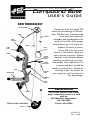
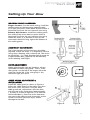
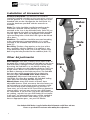
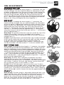
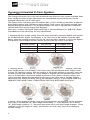
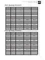
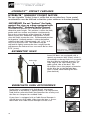
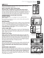
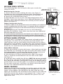
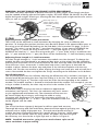
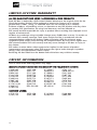
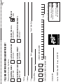
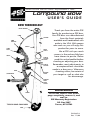
PRECISION SHOOTING EQ UIPMENT, INC .
Compound Bow
USER’S GUIDE
BOW TERMINOLOGY
IDLER WHEEL
LIMB
STRING
LIMB
POCKET
CABLE
LIMB
BOLT
PEEP
SIGHT
SIGHT
CABLE
GUARD
SLIDE
CABLE
GUARD
GRIP
STRING
LOOP
STABILIZER
Thank you from the entire PSE
family for purchasing a PSE bow.
Your PSE bow was manufactured
from the finest materials
available and handcrafted with
pride in the USA. With proper
care and use you will enjoy this
product for years to come.
We at PSE wish you much
success in the archery field you
have chosen to pursue. Please
read this entire booklet before
shooting or adjusting your bow.
Remember, most adjustments to
a compound bow should be
made in a bow press. Whenever
shooting a bow, be certain of
your target as well as what else
lies downrange.
ARROW
REST
BOW
SLING
RISER
TYPICAL ONE-CAM BOW
REGISTRATION
Fill out the reverse side of this
page completely, remove it, and
mail to:
PSE Warranty Registration
P.O. Box 5487
Tucson, AZ 85703
CAM
PN 94418
Rev. 11/06
YOUR LOCAL AUTHORIZED PSE DEALER IS YOUR BEST SOURCE
FOR INFORMATION AND ASSISTANCE. VISIT THEM FOR THESE
AND OTHER TYPICAL SERVICES:
1.
2.
3.
4.
5.
6.
7.
Adjusting draw length and draw weight
Adjusting / changing let-off
Replacing / servicing strings and cables
All aspects of bow tuning
Correct arrow selection
Mounting new accessories
Adjusting tiller
IMPORTANT
WARRANTY REGISTRATION
THIS FORM MUST BE RECEIVED BY PSE WITHIN 30 DAYS OF PURCHASE TO ACTIVATE WARRANTY
SERIAL # OF BOW
BOW MODEL
NAME
ADDRESS
ADDRESS
APT
CITY
STATE
COUNTRY
POSTAL CODE
EMAIL ADDRESS
/
/
PHONE (
)
MAIL TO: PSE WARRANTY REGISTRATION
P. O. BOX 5487
TUCSON, AZ 85703
DATE PURCHASED
PRECISION SHOOTING EQUIPMENT, INC .
Compound Bow
USER’S GUIDE
BOW TERMINOLOGY
IDLER WHEEL
LIMB
STRING
LIMB
POCKET
CABLE
LIMB
BOLT
PEEP
SIGHT
SIGHT
CABLE
GUARD
SLIDE
CABLE
GUARD
GRIP
STRING
LOOP
STABILIZER
Thank you from the entire PSE
family for purchasing a PSE bow.
Your PSE bow was manufactured
from the finest materials
available and handcrafted with
pride in the USA. With proper
care and use you will enjoy this
product for years to come.
We at PSE wish you much
success in the archery field you
have chosen to pursue. Please
read this entire booklet before
shooting or adjusting your bow.
Remember, most adjustments to
a compound bow should be
made in a bow press. Whenever
shooting a bow, be certain of
your target as well as what else
lies downrange.
ARROW
REST
BOW
SLING
RISER
TYPICAL ONE-CAM BOW
REGISTRATION
Fill out the reverse side of this
page completely, remove it, and
mail to:
PSE Warranty Registration
P.O. Box 5487
Tucson, AZ 85703
CAM
PN 94418
Rev. 11/06
Compound
Bow
USER’S GUIDE
General Operating Instructions
• Always inspect your bow thoroughly before each shooting session to insure that it is in
good working order. Check for worn or missing components and have them replaced
as required, i.e. bushings, spacers, etc.
• Inspect your arrows to insure that they are straight and that each nock is in good
condition. A cracked nock can break when fired from the bow and cause the bow to
"dry fire" resulting in possible injury to the archer and damage to the bow.
• When purchasing arrows for your bow, consult the selection chart from the arrow
manufacturer and select the correct arrow for your application. Always use an arrow
that meets the weight requirement marked on the specification label on the lower limb
of your bow. Failure to do so could cause personal injury and damage to your bow.
Bow Maintenance
Your PSE bow will give you many years of service if maintained and cared for properly.
IMPORTANT: Before servicing any PSE bow in a bow press, back out each limb bolt 4
complete turns from bottomed position.
• Keep synthetic cables and strings waxed. Apply bow string wax to your synthetic cables
and string before each shooting session.
• Strings and cables must be replaced periodically. A worn cable or string can suddenly
break causing serious injury to the archer and damage to the bow. It is recommended
that the string and cables be replaced at least every 5,000 shots or 12 months.
• Always store your bow in a cool dry place. High temperatures, such as those that can
occur in a truck or interior of a vehicle, can cause serious damage to your bow.
• After use in high humidity or damp conditions, wipe metal components of bow with
a light oil.
Safety
As with any weapon, safe operation of your PSE bow must always be the highest priority.
ALWAYS WEAR SAFETY GLASSES WHEN HANDLING A BOW.
Do not attempt to use your bow without proper instruction. Doing so can result in
serious injury.
a. Never "dry-fire" any bow. Dry-fire is to draw and release the bowstring without an
arrow on the string. Dry-firing will likely cause damage to the bow and serious injury
to the archer.
b. Always be sure of your intended target as well as what lies behind the target area. An arrow
can travel a considerable distance, so it is important to have a safe and sound backstop.
c. If you draw a bow and need to let it down, do so in a slow and careful manner. Keep
your support arm straight and prepare for a rapid and violent let-down. Avoid hitting
your hand on protruding accessories such as the cable guard or quiver. Keep your
head and face back and out of danger during let-down. Never draw a bow with a
peak weight above your comfort level. Always use a bow sling when drawing a bow.
d. Never modify any part of the bow or its components by drilling extra holes or
removing material. This voids the warranty and presents safety problems.
4
Compound
Bow
USER’S GUIDE
Setting-Up Your Bow
NOCKING POINT PLACEMENT:
Finger shooters: For the initial setting, install the
nocking point on the bowstring approximately
5/16" plus the arrow width above a point where a
horizontal line from the rest intersects the string.
Release Aid shooters: Install the nocking point
the width of the arrow above a point where a
horizontal line from the rest intersects the string.
When the arrow is in position on the rest the
arrownock should fit snug against the bottom of
the nocking point.
ARROWREST ADJUSTMENT:
The in/out position of the arrowrest should be
adjusted so that the arrow is in alignment with the
string when shooting with a release aid. The arrow
tip should be ~1/2 shaft diameter left of center on
a right-handed bow, (opposite for left-handed)
when shooting with fingers.
SIGHT ADJUSTMENT:
When adjusting the sight pin locations, always
remember to "follow the group". That is, if the
shot group is to the left of the target, move the
sight pins to the left. If the shot group is low,
move the sight pins down.
••
•
CABLE GUARD ADJUSTMENT &
INSTALLATION:
Install the cable guard as shown in Figure A.
Adjust the cable guard so the cables just clear
the arrow vanes. On bows using an offset
cable guard rod, adjustments must be done
with the rod in the up position (approximately
1 o’clock) as shown in Figure B (11 o’clock for
left handed bows). Excessive arrow clearance
may cause the cable to track incorrectly on the
wheels and cause personal injury and/or
damage to the bow.
Figure A
Figure B
5
Compound
Bow
USER’S GUIDE
Installation of Accessories
Arrowrest/Overdraw: The arrowrest or overdraw
should be installed according to the instructions received
with the product. It is usually mounted to the riser in the
threaded hole on the side opposite the shelf (hole "A")
using the hardware provided with the arrowrest or
overdraw.
Sight: The sight should be installed according to the
instructions received with the product. It is usually
mounted to the riser in the threaded holes (holes "B") on
the side opposite the shelf using the hardware provided
with the sight. Some bows are equipped with multiple
sight mounting holes which allow the sight to be moved
up or down.
Stabilizer: The stabilizer should be mounted according
to the manufacturer's recommendation. It is usually
mounted in the threaded hole on the front of the riser
(hole "C").
Bow Sling: The bow sling attaches to the riser of the
bow generally with the stabilizer. If a stabilizer is not
used, attach the sling to the riser with the correct sized
bolt using the hole provided for the stabilizer (hole "C").
Holes
B
Hole
A
Other Adjustments
Draw Weight: Your bow is factory-set to within 2 lbs. of
the peak draw weight indicated on the label on the lower
limb of the bow. Changes in draw weight can be made
by turning the limb bolt in or out. Before making any
changes in weight, turn the limb bolt clockwise until it no
longer moves. Never use extreme torque when turning
the bolt or damage to the limb may occur. The limb bolt
then may be turned counterclockwise to obtain the
desired weight, but NEVER more than 4 turns or
revolutions. Adjust each limb exactly the same.
CAUTION: On some bow models, the limb bolt locking
screw MUST be loosened BEFORE adjusting.
Wheels/Cams: Many PSE wheels and cams have
adjustable features. Each one comes from the factory setup and ready to use but there may be occasions where
you need to adjust the characteristics of your bow. In
some cases you will need a PSE Tune Chart to determine
what to adjust, and you may need to see a PSE Dealer
for information. If you are not sure of the adjustment you
are making, stop and see your PSE Dealer for assistance.
In all cases, an appropriate bow press will be needed to
make adjustments to cams and wheels. If you do not
have an appropriate press, see your PSE Dealer.
Hole
C
Your Authorized PSE Dealer is supplied with technical information on PSE bows and cams.
Please see your Dealer for assistance when making these adjustments.
6
Compound
Bow
USER’S GUIDE
CAM ADJUSTMENTS
STANDARD ONE CAM
Draw Length: To change the draw length in 1” increments, the cam
must be changed. See your local PSE dealer for information on how
to obtain a replacement cam. For minor changes in draw length, the
bow must be placed in a suitable bow press and tension relieved
from the string and cable. Moving the string to the post that will
shorten the effective length of the string will shorten the draw length
by ½”. Moving the string to the post that will lengthen the effective
length of the string will lengthen the draw length by ½”.
Standard One Cam
NRG PLUS™
Draw Length: To change the draw length in 1” increments, the
module must be changed. See your local PSE dealer for information
on how to obtain a replacement module. For minor changes in draw
length, the bow must be placed in a suitable bow press and tension
relieved from the string and cable. The string side of the cam has
three posts. Moving the string from the post with the dot to the post
with the “+” will increase draw by approximately ¼”. Moving the
string from the post with the dot to the post with the “-” will decrease
draw by approximately ¼”.
Draw Stop: The position of the draw stop must match the size of the
module. For example, if the cam is equipped with a number 7
module the draw stop must be placed in one of the draw stop holes
marked with a “7”.
Let-Off: Let-off adjustment is part of the draw stop. To adjust from 80%
to 65% let-off, remove the draw stop from the 80% hole and reinstall it
in the 65% hole of the corresponding the module number. For
example, if the cam is equipment with a number 7 module the stop
must be reinstalled in the hole marked “7” in the row marked “65%”
NRG Plus™
NRG™ HYBRID CAM:
Draw Length: To change the draw length in 1” increments, the modules NRG™ Hybrid Cam
must be changed on both the top and bottom cams. See your local PSE
TOP
dealer for information on how to obtain replacement modules. For minor
changes in draw length, the bow must be placed in a suitable bow press
and tension relieved from the string and cable. Move the string to the
“+” post on the top cam to increase the draw by approximately 3/8” or
to the “-“ post to decrease the draw by approximately 3/8”. The Short
Draw cams have the “+” post only. Moving the string to the “+” post will
increase draw by approximately 3/8”.
Draw Stop: The draw stop is located on the bottom cam and is
attached with two screws. It must be placed in the position that
corresponds with the modules. For example, if the cams are equipped
with number 7 modules, the draw stop must be secured firmly with
NRG™ Hybrid Cam
the two mounting screws in the number “7” holes.
BOTTOM
Let-Off: The let-off adjustment is part of the draw stop. To adjust
from the factory setting of 80% to 65%, remove both screws that hold
the stop to the cam and flip it over so the cable will contact the side
marked “65%” at full draw and reinstall the screws. Note: Changing
the let-off from 80% to 65% shortens the draw by approximately 3/8”
STAGE 3™:
Draw Length: The draw length is adjusted by placing the bow in an
appropriate bow press and relieving the tension from the string and
cables. Move the string to the slot that will shorten the effective
length of the string to shorten the draw length by ½" per wheel.
Move the string to the slot that will lengthen the effective length of
the string to lengthen the draw of the bow by ½" per wheel.
Stage 3™
7
Compound
Bow
USER’S GUIDE
Synergy Universal 2-Cam System
The Synergy Universal Cam is the most advanced entry-level two-cam system available. Both
draw weight and draw length adjustments are incorporated into the design and can be
changed without the use of a bow press.
The system comes with three pairs of modules (8912, 8913 and 8914) that allow 6 different
draw length settings and 3 different weight settings. Each system will function on both righthanded and left-handed bows. The illustration below will show a right-handed installation.
Left-handed will be mirror image of all diagrams.
Each cam is marked “RHT/LHB” (Right-Hand Top or Left-Hand Bottom) or “RHB/LHT” (RightHand Bottom or Left-Hand Top) for easy identification.
1.Selecting the draw length setting: From the charts provided, select the Module size needed
for the desired draw length. For example, a 28” Nova uses a #8 module. From the table
below, select the module required. For the 28” Nova the 8914 Module is used in the flipped
over position. Place module on the cam but do not install the screws at this point.
Module Number
Size (normal)
Size (flipped over)
8912
8913
8914
#11
#10
#9
#6
#7
#8
2. Selecting the draw weight setting: From the charts provided on the next page, select the
draw weight desired. For example, a 28” Nova with a 65-pound peak draw weight would
use the “M” (Medium) setting. With the module in the proper position on the cam, move the
module until the hole marked “M” in the module is aligned with the threaded hole in the
cam, as shown below. Secure the module to the cam in two places with the washers and
screws provided. Repeat this operation for the cam on the other end of the bow. Weight
adjustments can also be made by turning the limb bolts either in or out. NEVER TURN THE
LIMB BOLT OUT MORE THAN 4 TURNS FROM THE FULLY BOTTOMED POSITION.
3.NOTES: When changing weight using module adjustments, the following can be expected:
from Light “L” to Medium “M”, draw length increased by ¼”. From Medium “M” to Heavy
“H”, draw length increases ¼”. Be aware that let-off varies with draw length changes. Some
variations in Let-off, length of “valley” and firmness of “wall” may occur when changing
module settings.
8
Compound
Bow
USER’S GUIDE
Nova Synergy Universal
MODULE
NO.
11
11
11
10
10
10
9
9
9
8
8
8
7
7
7
6
6
6
WEIGHT
SETTING
H
M
L
H
M
L
H
M
L
H
M
L
H
M
L
H
M
L
APPROX. DRAW
LENGTH
31 ½
31 ¼
31
30 ½
30 ¼
30
29 ½
29 ¼
29
28 ½
28 ¼
28
27 ½
27 ¼
27
26 ½
26 ¼
26
Approx Weight
60# PEAK
50-60
45-55
40-50
50-60
45-55
40-50
50-60
45-55
40-50
50-60
45-55
40-50
50-60
45-55
40-50
50-60
45-55
40-50
Range
70# PEAK
60-70
55-65
50-60
60-70
55-65
50-60
60-70
55-65
50-60
60-70
55-65
50-60
60-70
55-65
50-60
60-70
55-65
50-60
Approx Weight
60# PEAK
50-60
45-55
40-50
50-60
45-55
40-50
50-60
45-55
40-50
50-60
45-55
40-50
50-60
45-55
40-50
50-60
45-55
40-50
Range
70# PEAK
60-70
55-65
50-60
60-70
55-65
50-60
60-70
55-65
50-60
60-70
55-65
50-60
60-70
55-65
50-60
60-70
55-65
50-60
Bruin Synergy Universal
MODULE
NO.
11
11
11
10
10
10
9
9
9
8
8
8
7
7
7
6
6
6
WEIGHT
SETTING
H
M
L
H
M
L
H
M
L
H
M
L
H
M
L
H
M
L
APPROX. DRAW
LENGTH
30 ½
30 ¼
30
29 ½
29 ¼
29
28 ½
28 ¼
28
27 ½
27 ¼
27
26 ½
26 ¼
26
25 ½
25 ¼
25
9
Compound
Bow
USER’S GUIDE
HYPERLITE™ POCKET FEATURES
HYPERLITE™ UNIBODY POCKET NOTICE
The new Hyperlite™ Pocket System is unlike that on any other bow. Some special
considerations must be followed so that the system continues to function properly.
·IMPORTANT: Do not “bottom” the limbs
against the riser on a bow equipped with
the HyperLiteTM Unibody Pocket System!
Traditional limb pockets use a “bottomed” position to
determine peak weight. This position is where the limb,
pocket and riser contact one another simultaneously.
Due to the unique design of the HyperLite™ Unibody
Pocket System, the “bottomed” limb position is NOT
when the limbs contact the riser. The bottomed position
for HyperLite™ Unibody pockets is where the bottom
surface of the limb is approximately .20” (3/16” or 5
mm) away from the riser. The limb bolt may be
adjusted to slightly increase the draw weight, but the
gap between the limb and riser must never be less than
0.15” (4 mm).
ASYMMETRIC IDLER
Wide edge
Under-limb pad
removed for clarity
Some PSE bows are equipped with a
special asymmetric idler wheel, which is
assembled on the top limb. It is essential
that the idler be oriented properly. The
wide edge of the idler always goes to
cable guard side of the bow. The
illustration shows the proper orientation
of the idler for a right-handed bow
when viewed while holding the bow
(from behind).
VIBRACHECK HUSH ACCESSORIES
If your bow is equipped with limb bands, the proper
placement of the bands is approximately 1/8” beyond the
limb fork for pultruded limbs and between the overlay and
the flare on compression molded limbs.
If your bow is equipped with a Cable Guard Damper it
should be even with cable slide when the bow is at rest.
More than one Cable Guard Damper can be used.
10
Pultruded Limb
Compression Molded Limb
Compound
Bow
USER’S GUIDE
MACH X
The X Technology bows come with many unique features that will
enhance your archery experience.
MULTI POSITION SIGHT MOUNTING
The Mach X bow is equipped with a multi-position sight-mounting
feature allowing the sight to be mounted to optimize your sight
window. Mount the sight in the middle position and sight in the bow.
Your pin grouping should be centered on the sight body. If the pins are
too high, move the sight to the upper mounting position. If they are
too low move the sight to the lower position. Sight in the bow again.
INDEPENDENTLY ADJUSTABLE PIVOTING
POCKET SYSTEM
The X Technology bows are equipped with an innovative limb
pocket system.
Start with the sight
mounted in the middle
set of holes
Limb Pocket
Do not make any adjustment to this system without referring to the
instructions in this manual.
MAINTENANCE
Your bow is a mechanical device that is subject to wear and therefore
must be inspected periodically and given the proper adjustments and
service. It is recommended that this service be performed at least
once a year by an authorized PSE dealer. All components, including
string, cable, axles, e-clips, limbs and riser should be carefully
inspected for damage or wear.
Half Round Underlay
USING A BOW PRESS
Use only a PSE approved bow press to service an X Technology bow.
Never allow your bow to be placed in a bow press with conventional
rollers. Check our website (www.pse-archery.com) for a current list of
approved bow presses.
STRINGS AND CABLES
Apply a light coat of high quality bowstring wax to your string and
cable once every two weeks under normal shooting conditions. It is
especially important to wax the area of the string that wraps around
the idler wheel since this portion of the string is not served. This will
help reduce wear on your string and cable. Use a good quality wax
from your authorized dealer. Inspect the string and cables regularly
and replace them when there is evidence of wear.
LUBRICATION POINTS
When removing the limbs for service always make sure that the area
between the half rounds and the limb pockets are lubricated with
medium-weight grease. Also lubricate the surfaces in the pocket
areas where the limbs make contact with the riser with the same
grease.
Alignment
Pins
Figure 1
Place roller
close to the end
of the limbs
PSE Approved Bow Press
ADJUSTING LIMB BOLTS
Before making any adjustments to the limb bolts, the 4 side locking
tab screws and the 4 limb bolt locking screws must be loosened (see
Figure 2). Limb bolt adjustments must be made in increments of no
more than one-turn each. There should never be a differential of
more than 2 turns at any time between limb bolts. After limb bolt
adjustments are complete tighten the 4 locking tab screws and the
4 limb bolt locking screws.
A typical bow press will damage X
Technology bows. DO NOT USE!
11
Compound
Bow
USER’S GUIDE
NO BOW PRESS OPTION
The X Technology bows do not require a bow press to relax the
strings for service.
Locking Tab Screw
NEVER ADJUST OR
REMOVE THIS SCREW!
Limb Bolt
Locking Screw
Relax Strings for Service
1. Loosen and remove the 4 locking tab screws (see Figure 2).
Damage may occur to the limbs at the pin holes if the locking tab
screws are not removed before fully backing out the limb bolts.
2. Loosen the 4 limb bolt locking screws.
3. Back limb bolts out one turn at a time alternating between all 4
limb bolts. Never have more than 2 turns differential between the limb
bolts at any time. Back the limb bolts out until they are flush with the
anchor (see Figure 2).
Tighten Strings after Service
1. Check to make sure the all the half rounds and underlays are installed and
properly seated between the limbs. Note: It is important that the underlay is
seated properly over the pin on the half round and the pin on the pocket.
(see Figure 1).
2. Begin tightening the limb bolts one turn at a time alternating
between all 4 limb bolts. Never allow more than two turns differential
between limb bolts at any time.
3. Once the limbs have bottomed, the wheel attitude can be adjusted, if needed. (see
the Setting Wheel Attitude section for this procedure) and then set the poundage.
4. Reinstall the 4 side locking tab screws and tighten the limb bolt locking screws.
Limb Bolt
Back limbs out until they
are flush with the bottom
of anchor
Figure 2
SETTING WHEEL ATTITUDE
The Mach X bow is equipped with independently adjustable pivoting
limb pockets. This allows for the adjustment of wheel attitude. The
wheel attitude is pre-set at the factory and will remain true as long as
adjustments to the limb bolts are made in the same increment for each
limb bolt. For example, if you would like to decrease the draw weight of
the bow by 3 to 4 pounds, back each limb bolt out exactly one turn.
Adjust Wheel Attitude
1. Adjust top wheel by using the split harness. When looking at the bow
from the back (as if shooting), the right side of the split harness should
have approximately 12 twists more than the left. It is not necessary to
use the limb bolts to adjust the attitude of the top wheel.
2. Draw the bow to full draw and observe the cable in the bottom
wheel. It should be centered between the two tracks of the wheel
(see Figure 3).
3. Let the bow down carefully from full draw. NOTE: Do not use an arrow!
4. If the string is not near the center between the two cam tracks at full
draw, adjust the limb bolts (with the bow at rest) on the bottom limbs to
get the wheel to sit so that the cable is as centered as possible between
the two tracks at full draw. See Figure 3 for details. Never have more
than two turns differential between the limb bolts.
Cable should be
centered on cam tracks
If cable is on the left,
back out the right or
tighten the left limb bolt
WHEEL SPACING
Spacing for the top wheel should be one medium spacer on both sides
of the wheel. If there is any extra play in the assembly then 1 or 2 thin
spacers can be added to the OUTSIDE of the limb inside the E-clip.
Spacing for the bottom cam should be one thin spacer on the shelf side
of the cam and one thin spacers on the opposite side. If there is any
extra play in the assembly add an additional thin spacer to the side
opposite the shelf.
12
If cable is on the right,
back out the left or
tighten the right limb bolt
Figure 3
Compound
Bow
USER’S GUIDE
WARNING: DO NOT SHOOT ABOVE BOW’S LISTED PEAK WEIGHT
The limbs have been optimized to perform their best at peak weight. Even though your bow
may be capable of being adjusted to higher weights, DO NOT DRAW OR SHOOT any PSE bow
higher than peak weight. Drawing or shooting the bow above peak weight could cause serious
injury as well as void the warranty.
Module Screws
Draw Stop Screw w/
washer (shown in #11
module, 80% position)
Module
Dot ”.” Posts
Plus ”+” Post
Minus “-“ Post
X CAM
Orientation
Reference Mark
Draw Stop
Figure 4
Adjusting Draw Length in Small Increments
The X Cam can be adjusted in small increments by changing the string to different post
positions. To change post positions the bow must be either placed in an approved bow press or
the strings must be relaxed by backing out the limb bolts (see instructions on page 12 of this
manual). The string is set on the dot “.” post from the factory. If you want to DECREASE the
draw length by ½”, move the string to the minus “-“ post (see Figure 4). If you want to
INCREASE the draw by ½”, move the string to the plus “+” post. If the string is installed on the
plus “+” post and the minus “-“ post, the draw will be shortened by ¼” from the factory setting.
Adjusting Draw Length in 1-inch Increments
For draw length changes in 1-inch increments the module must be changed. To change the
module the bow must be placed in an approved bow press or the strings must be relaxed by
following the instructions in this manual. Remove the axle from the limbs and remove the cam.
Once the cam is free, remove the 3 socket head cap screws (see Figure 4) that hold the
module in place. Remove the draw stop and place in the slot that correlates with the new
module size. Put the new module in place aligning the large and small pins and reinstall the 3
screws. Reassemble the bow and tighten the strings according to the directions in this bulletin.
Let-off Adjustment:
The X Cam has provisions for infinitely adjusting let-off between 65% and 80% (see figure 4).
Set the let-off by loosening the draw stop and sliding it in the slot. The extreme ends of the slot
are labeled (see Figure 4). The draw stop must be in the slot corresponding to the module
number. The module number is located on the backside of the module. For example if you are
using a number 9 module, the draw stop must be in the number 9 slot.
Orientation
Cam Orientation:
A reference mark is found on the cam to indicate an approximate
orientation (see Figure 5). This line is for reference only and is meant
to give approximate orientation only. The orientation of the cam can
be moved slightly by twisting or untwisting the cable or string.
Changing post attachments will change the orientation of the cam. If
attaching the string to the “+” or the “-“ post, the orientation mark will
not be aligned with the cable.
Reference Mark
Figure 5
Tuning:
The X Cam has been rigorously designed to deliver speed and accuracy.
Thorough lab testing and field evaluations determined that optimal grouping was
achieved with a slightly high paper tear. The nock-travel profile of every X
module has been engineered around this specific design criterion. While paper
tuning results are not the same for every archer, the paper tear delivering the
best accuracy was found to be a slight high tear as shown in Figure 6.
Figure 6
NOTE: Installed accessories, grip pressure and release style can all
cause variations in paper tuning
13
Compound
Bow
USER’S GUIDE
LIMITED LIFETIME WARRANTY
ALL PSE MANUFACTURED BOWS / ACCESSORIES / KING PRODUCTS
Each PSE Bow is backed by a PSE Limited Lifetime Warranty to the original owner for the
life of the product. Product will be replaced or repaired to restore it to its original
performance. Cables, strings, or wearable items are not covered by this warranty.
Evidence of abuse, mishandling, misuse, or alteration to any PSE product voids any claim
to warranty. PSE specifications on strings and harnesses must be adhered to.
PSE cannot be held responsible for injury or product failure resulting from improper use or
neglect of maintenance.
All bows must undergo string and cable changes every 5,000 shots or every 12 months to
maintain PSE warranty coverage. Total arrow weight must be in accordance with the
recommendations made by the Archery Trade Association (ATA) for minimum arrow
weight/bow peak weight. Overstressing PSE compound bows by using arrows lighter than
ATA recommendation will void warranty and may cause damage to the bow or injury to
the shooter.
PSE makes no other claims either expressed or implied. In the interest of product
improvement and consumer safety, PSE reserves the right to make changes in product
design, color, and specifications without notice.
Removing the data label from the bottom limb of the bow may void the warranty.
PATENT INFORMATION
One or more of the following patents may apply:
MANUFACTURED UNDER ONE OR MORE OF THE FOLLOWING PATENTS:
4,649,889
4,947,823
5,054,462
5,243,958
5,335,644
5,469,834
5,505,185
5,762,060
6,176,231 B1
6,968,837
5,782,229
4,697,350
4,967,721
5,123,396
5,280,779
5,339,790
5,479,712
5,507,270
5,914,775
6,360,735
DES 429,309
4,735,667
5,005,554
5,190,022
5,301,651
5,365,650
5,487,373
5,657,739
5,960,778
6,493,951 B1
RE-36,942
4,762,112
5,020,507 B1
5,241,945
5,307,787
5,377,658
5,495,843
5,678,529
6,112,732
6,792,930
D 528,625
5,141,689
5,505,185
5,368,006
5,809,982
LICENSED UNDER:
4,519,374
5,392,756
14
4,976,250
5,501,208
)
CREDIT CARD NUMBER
Mail to: PSE P.O. Box 5487 Tucson, AZ 85703
SIGNATURE
AMEX
MC
DISC VISA
OR INCLUDE CHECK OR MONEY ORDER
Daytime Phone (
City
Address
State
HOLDING STEADY
DVD 41302
DANGEROUS GAME
DVD 41349
Name
ALL THE RIGHT MOVES
DVD 41401
WHITETAIL FEVER 4
DVD 41350
Please select two videos from below:
YES, SEND ME TWO DVD VIDEOS AND MY FREE CAP!
FREE CAP
45354
Postal Code (Zip)
AZ residents add $ 1.32
Total (AZ residents) $ 24.26
Shipping & Handling $ 3.95
Total (non-AZ residents) $ 22.94
$ 18.99
Sorry, available to US residents only.
Exp
BOWHUNTING THE WILD WEST 3
DVD 41347
BOAR’N THE U.S.A.
DVD 41295
THANK YOU FOR
SELECTING PSE
Act now on this
one-time offer:
$
99
18
Buy any TWO of these
exciting PSE DVDs and
receive a FREE cap!
CAP STYLE SHOWN MAY VARY
Offer good in the United States Only
BOWHUNTING THE
WILD WEST 3
From Alaska to Arizona,
some of the best hunts in
the West. – DVD
ALL THE RIGHT MOVES
Ralph Ramos takes you on
amazing elk hunts while
teaching you his successful
calling and hunting techniques. – DVD
BOWHUNTING
DANGEROUS GAME
Bowhunting around the
world! Polar bear, lion, elephant, crocodile, leopard,
brown bear and more. –
DVD
BOAR’N THE U.S.A.
From Florida to California
PSE is hunt’n the Wild Boar.
– DVD
HOLDING STEADY
Learn to really aim your
bow. – DVD
WHITETAIL FEVER 4
PSE Pro Staff members
hunting whitetail across
North America in this next
chapter of the popular
series. – DVD