1
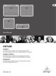
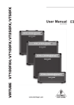
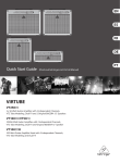
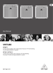
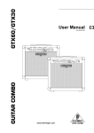
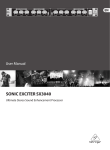
User Manual
VIRTUBE
VT250
2 x 50-Watt Guitar Amplifier with 2 Independent Channels,
VTC Tube Modeling, Dual FX and 2 Original BUGERA 12" Speakers
VT100
/VT50
100/60-Watt Guitar Amplifier with 2 Independent Channels,
VTC Tube Modeling, Dual FX and Original BUGERA 12" Speaker
VT100
H
100-Watt Guitar Amplifier Head with 2 Independent Channels,
VTC Tube Modeling and Dual FX
2
VIRTUBE VT250FX/VT100FX/VT50FX/VT100FXH User Manual
Table of Contents
Thank you........................................................................ 2
Important Safety Instructions....................................... 3
Legal Disclaimer.............................................................. 3
Limited warranty............................................................. 3
1. Introduction................................................................ 4
1.1 Before you get started....................................................... 4
1.1.1 Online registration......................................................... 4
2. Control Elements........................................................ 4
2.1 Front panel............................................................................. 4
2.1.1 CLEAN CHANNEL............................................................ 4
2.1.2 OVERDRIVE CHANNEL.................................................. 4
2.1.3 DIGITAL FX........................................................................ 5
2.1.4 MASTER section.............................................................. 5
2.2 Rear panel.............................................................................. 5
2.2.1 FX LOOP............................................................................ 5
3. Application Examples................................................ 6
3.1 Set-up for practicing with playbacks............................ 6
3.2 Recording set-up with effects device.......................... 6
3.3 Live set-up with external speaker box......................... 7
3.4 Wiring the VT100FXH......................................................... 7
4. Installation.................................................................. 8
5. Specifications ............................................................. 9
Thank you
Congratulations! With the VIRTUBE, you have the newest generation of
guitar amps. It offers an extremely broad range of options and possibilities,
the only limit being your own creativity. The VIRTUBE is an allrounder with so
many features that you hardly need any other equipment.
3
VIRTUBE VT250FX/VT100FX/VT50FX/VT100FXH User Manual
Important Safety
Instructions
Terminals marked with this symbol carry
electrical current of sufficient magnitude
to constitute risk of electric shock.
Use only high-quality professional speaker cables with
¼" TS or twist-locking plugs pre-installed. All other
installation or modification should be performed only
by qualified personnel.
This symbol, wherever it appears,
alerts you to the presence of uninsulated
dangerous voltage inside the
enclosure - voltage that may be sufficient to constitute a
risk of shock.
This symbol, wherever it appears,
alerts you to important operating and
maintenance instructions in the
accompanying literature. Please read the manual.
Caution
To reduce the risk of electric shock, do not
remove the top cover (or the rear section).
No user serviceable parts inside. Refer servicing to
qualified personnel.
Caution
To reduce the risk of fire or electric shock,
do not expose this appliance to rain and
moisture. The apparatus shall not be exposed to dripping
or splashing liquids and no objects filled with liquids,
such as vases, shall be placed on the apparatus.
9. Do not defeat the safety purpose of the polarized
or grounding-type plug. A polarized plug has two blades
with one wider than the other. A grounding-type plug
has two blades and a third grounding prong. The wide
blade or the third prong are provided for your safety. If the
provided plug does not fit into your outlet, consult an
electrician for replacement of the obsolete outlet.
10. Protect the power cord from being walked on or
pinched particularly at plugs, convenience receptacles,
and the point where they exit from the apparatus.
11. Use only attachments/accessories specified by
the manufacturer.
12. Use only with the
cart, stand, tripod, bracket,
or table specified by the
manufacturer, or sold with
the apparatus. When a cart
is used, use caution when
moving the cart/apparatus
combination to avoid
injury from tip-over.
13. Unplug this apparatus during lightning storms or
when unused for long periods of time.
14. Refer all servicing to qualified service personnel.
Servicing is required when the apparatus has been
damaged in any way, such as power supply cord or plug
is damaged, liquid has been spilled or objects have fallen
into the apparatus, the apparatus has been exposed
to rain or moisture, does not operate normally, or has
been dropped.
15. The apparatus shall be connected to a MAINS socket
outlet with a protective earthing connection.
16. Where the MAINS plug or an appliance coupler is
used as the disconnect device, the disconnect device shall
remain readily operable.
Caution
These service instructions are for use
by qualified service personnel only.
To reduce the risk of electric shock do not perform any
servicing other than that contained in the operation
instructions. Repairs have to be performed by qualified
service personnel.
1. Read these instructions.
2. Keep these instructions.
3. Heed all warnings.
4. Follow all instructions.
5. Do not use this apparatus near water.
6. Clean only with dry cloth.
7. Do not block any ventilation openings. Install in
accordance with the manufacturer’s instructions.
8. Do not install near any heat sources such as
radiators, heat registers, stoves, or other apparatus
(including amplifiers) that produce heat.
LEGAL DISCLAIMER
TECHNICAL SPECIFICATIONS AND APPEARANCES
ARE SUBJECT TO CHANGE WITHOUT NOTICE AND
ACCURACY IS NOT GUARANTEED. BEHRINGER,
KLARK TEKNIK, MIDAS, BUGERA, AND TURBOSOUND
ARE PART OF THE MUSIC GROUP (MUSIC-GROUP.COM).
ALL TRADEMARKS ARE THE PROPERTY OF THEIR
RESPECTIVE OWNERS. MUSIC GROUP ACCEPTS NO
LIABILITY FOR ANY LOSS WHICH MAY BE SUFFERED
BY ANY PERSON WHO RELIES EITHER WHOLLY OR
IN PART UPON ANY DESCRIPTION, PHOTOGRAPH
OR STATEMENT CONTAINED HEREIN. COLORS AND
SPECIFICATIONS MAY VARY FROM ACTUAL PRODUCT.
MUSIC GROUP PRODUCTS ARE SOLD THROUGH
AUTHORIZED FULLFILLERS AND RESELLERS ONLY.
FULLFILLERS AND RESELLERS ARE NOT AGENTS OF
MUSIC GROUP AND HAVE ABSOLUTELY NO AUTHORITY
TO BIND MUSIC GROUP BY ANY EXPRESS OR IMPLIED
UNDERTAKING OR REPRESENTATION. THIS MANUAL
IS COPYRIGHTED. NO PART OF THIS MANUAL MAY
BE REPRODUCED OR TRANSMITTED IN ANY FORM
OR BY ANY MEANS, ELECTRONIC OR MECHANICAL,
INCLUDING PHOTOCOPYING AND RECORDING OF ANY
KIND, FOR ANY PURPOSE, WITHOUT THE EXPRESS
WRITTEN PERMISSION OF MUSIC GROUP IP LTD.
ALL RIGHTS RESERVED.
© 2013 MUSIC Group IP Ltd.
Trident Chambers, Wickhams Cay, P.O. Box 146,
Road Town, Tortola, British Virgin Islands
LIMITED WARRANTY
For the applicable warranty terms and conditions
and additional information regarding MUSIC Group’s
Limited Warranty, please see complete details online at
www.music-group.com/warranty.
4
VIRTUBE VT250FX/VT100FX/VT50FX/VT100FXH User Manual
1. Introduction
The demands placed on a guitar amp are nowadays very broad. A guitarist should
offer a wide array of sounds. That’s why it is very important to us to be able to
offer you maximum sound diversity as well as a variety of connection possibilities
with your VIRTUBE. Don’t worry: you will quickly master the VIRTUBE and learn
how to use all of its capabilities easily and intuitively. With its up-to-date
circuitry, the VIRTUBE features the functionality and reliability of a truly modern
guitar amp.
VTC Virtual Tube Circuitry
The specially developed VTC Virtual Tube Circuitry gives your sound the unique
vintage flavor of classic tube amps.
1.1 Before you get started
Your product was carefully packed at the factory to ensure safe transport.
Nevertheless, if the box is damaged inspect the unit immediately for signs
of damage.
◊ If the unit is damaged please do NOT return it to us, but notify your
dealer and the shipping company immediately; otherwise, claims for
damage or replacement may not be granted.
◊ Otherwise, always use the original box to prevent damage during
storage or transport.
◊ Make sure that children cannot play unsupervised with the unit or
Ensure adequate air supply and to avoid overheating do not place the unit
near radiators etc.
◊ Please make sure that all devices are properly grounded/earthed.
For your own safety, never remove or disable the ground/earth
conductors from the devices or on the power cords. The unit
must always be connected to the mains outlet with a protective
grounding connection.
1.1.1 Online registration
Please register your new BEHRINGER equipment right after your purchase
by visiting http://behringer.com and read the terms and conditions of our
warranty carefully.
Should your BEHRINGER product malfunction, it is our intention to have it
repaired as quickly as possible. To arrange for warranty service, please contact
the BEHRINGER retailer from whom the equipment was purchased. Should your
BEHRINGER dealer not be located in your vicinity, you may directly contact
one of our subsidiaries. Corresponding contact information is included in the
original equipment packaging (Global Contact Information/European Contact
Information). Should your country not be listed, please contact the distributor
nearest you. A list of distributors can be found in the support area of our website
(http://behringer.com).
Registering your purchase and equipment with us helps us process your repair
claims more quickly and efficiently.
Thank you for your cooperation!.
its packaging.
◊ Please ensure proper disposal of all packing materials.
Recylce whenever possible.
2. Control Elements
(2)
(9)
(17)
(1) (3) (4) (5) (6) (7) (8) (10) (11) (12) (13) (14) (15) (16)
(18) (19) (20) (21) (22) (23) (24) (25) (26)
Fig. 2.1: VIRTUBE control elements (front panel)
2.1 Front panel
(7) The TREBLE control adjusts the treble frequencies on the CLEAN channel.
(1) The INPUT socket is the 1/4" connector for your guitar. Please use a standard
1/4" TS connector.
(8) Press the CHANNEL button to switch between the CLEAN and OVERDRIVE
channels. The channel LED lights up when the channel is activated. With all
models you can also switch between channels using the footswitch provided.
2.1.1 CLEAN CHANNEL
(2) The CLEAN CHANNEL LED lights up when the CLEAN channel is active.
(3) The GAIN control determines the volume of the CLEAN channel.
(4) The CRUNCH button (VT100FXH and VT100FX only) allows you to add some
slight distortion to your clean sound, giving it a bit of “dirt” or “crunch”.
(5) The BASS control in the EQ section allows you to raise or lower the bass
frequencies on the CLEAN channel.
(6) With the MIDDLE control you can raise or lower the midrange frequencies
on the CLEAN channel.
2.1.2 OVERDRIVE CHANNEL
(9) The OVERDRIVE CHANNEL LED lights up when the channel is active.
(10) The GAIN control determines the amount of gain applied and hence the
degree of distortion in the OVERDRIVE channel.
(11) The OD1/OD2 button (VT100FXH and VT100FX only) switches between
two different overdrive sounds.
(12) The BASS control in the EQ section allows you to raise or lower the bass
frequencies on the OVERDRIVE channel.
5
VIRTUBE VT250FX/VT100FX/VT50FX/VT100FXH User Manual
2.1.4 MASTER section
(13) With the MIDDLE control (VT100FXH and VT100FX only) you can raise or
lower the midrange frequencies on the OVERDRIVE channel.
(14) The TREBLE control adjusts the treble frequencies on the OVERDRIVE channel.
(15) Use the CONTOUR control for additional, highly characteristic adjustment
of the midrange, allowing you to easily create traditional as well
as ultra-modern guitar sounds.
(23) The VTC push button activates and deactivates the VTC Virtual Tube Circuitry.
(24) The CD IN connector allows you to connect the output signal of a CD player,
tape deck, or CD/MD walkman. For example, you can play back music CDs or
CDs accompanying a guitar tutor while practising. This connector can also
be used as a LINE OUT output. In this case, the guitar signal is output with no
speaker simulation applied and can be routed to an external amp or mixing
console. This will not mute the VIRTUBE’s built-in loudspeaker.
(16) The VOLUME control adjusts the volume level of the OVERDRIVE channel.
2.1.3 DIGITAL FX
(17) The DIGITAL FX LED lights up when the effects processor is active.
(25) The LINE OUT/PHONES jack is for headphones connection. Internal speaker
simulation is applied to the headphones signal in order to produce an
authentic signal. The VIRTUBE’s built-in loudspeaker is muted when this
connector is used.
(18) Use the FX PRESET control to select one of 16 effects.
Preset
FX
1-4
5-8
9 - 12
13 - 16
Chorus/Delay
Delay
Chorus
Flanger
(22) The MASTER VOLUME control adjusts both the overall volume and
the line out/headphones volume.
◊ The headphones output signal can also be routed to a mixing console or
other sound reinforcement system. To do so, connect the headphones
output with the line input on the mixing console. Use a standard cable
with 1/4" TS connectors. If hum problems occur, you could insert a
DI box, e.g. BEHRINGER ULTRA-DI DI100 or DI120.
Tab. 2.1: Effects
(19) The FX LEVEL control adjusts the mix ratio between the original and
the effect signal.
◊ Some headphones tend to produce distortion with too high
(20) The REVERB LEVEL control determines the effect intensity of the
additional reverb effect.
(26) The POWER switch turns your VIRTUBE on and off. It should always be in the
OFF position when connecting the unit to the mains.
(21) The FX LOOP MIX control (VT100FXH and VT100FX only) determines
the effect intensity of the external effect (see Chapter 2.2.1 FX LOOP).
◊ Please note: Merely switching the unit off does not mean that it is fully
volume level. Please turn down the volume a bit, until distortion stops.
disconnected from the mains. To disconnect the unit from the mains,
pull out the mains connector. Before installation, please make sure
that the mains connector has not been damaged. If you do not use the
unit for an extended period of time, please disconnect it at the mains.
(28)
(27)
(30)
(29)
(35)
(33) (31) (32) (34)
Fig. 2.2: VIRTUBE control elements (rear panel)
2.2 Rear panel
(27) The VIRTUBE is connected to the mains using a standard IEC receptacle.
A suitable power cord is included with the unit.
(28) FUSE HOLDER/VOLTAGE SELECTOR. Before connecting the unit to
the mains, ensure that the voltage setting matches your local voltage.
Blown fuses must be replaced with a fuse of the same type and rating.
On some units, the fuse holder can be switched to one of two positions,
i.e. 230 V and 120 V. Please note: when operating the unit outside Europe at
120 V, a higher fuse rating is required (see Chapter 4, “Installation”).
(29) This is where the fan of the unit is located.
(30) The SPEAKER OUT connectors (only one on the VT100FX and VT50FX)
can be used to connect external speakers with a miminum impedance of
4 Ω. The outputs of the VT250FX deliver 50 Watts of power per channel
(L/R). Always use speakers with a minimum impedance of 8 Ω to ensure
maximum power output. Using the SPEAKER OUT connectors will mute the
built-in loudspeakers.
2.2.1 FX LOOP
(31) The FX LEVEL button allows you to adapt the FX LOOP to the operating level
of an external effects device (+4 dBu/-10 dBV).
(32) The VIRTUBE provides a serial insert path for inserting external effects
(e.g. reverb processor). To do so, connect the FX SEND jack to the input of the
effects device.
◊ The FX SEND can also be used as a parallel output with no effects,
for example, to record a “dry” guitar signal. As long as the RETURN jack
is not in use, there will be no break in the internal signal path.
6
VIRTUBE VT250FX/VT100FX/VT50FX/VT100FXH User Manual
(33) Connect the FX RETURN jack to the output of the external effects device.
The VT250FX has two jacks (L/R) because it is a stereo amplifier.
(34) Use the FOOTSWITCH jack to connect the 1/4" TRS plug of the footswitch
supplied with the unit. The footswitch performs a dual function: it switches
between the two channels and turns the DIGITAL FX on and off.
(35) SERIAL NUMBER.
3.2 Recording set-up with effects device
DSP2024P
FX In
FX Out
DAT Recorder
3. Application Examples
The VIRTUBE features plenty of connectors for a wealth of applications.
Here’s a few examples of how flexible your VIRTUBE can be:
FX Send
FX Return
Line Out
3.1 Set-up for practicing with playbacks
Footswitch
Drum Computer
VIRTUBE VT100FX
HPS3000
CD Player
CD In
Footswitch
Electric Guitar
Fig. 3.2: Recording set-up with the VT100FX
VIRTUBE VT50FX
If you want to use your VIRTUBE in a home-recording or studio environment,
please wire it as shown in Fig. 3.2. Of course, you can still use a CD player
or drum computer in this set-up. This is not shown here to provide for a
better overview. Connect the input of the effects device to the FX SEND and
the effects output to the FX RETURN.
If you want to record your guitar signal with effects, connect the PHONES output
to your mixing console, audio sequencer or multi-track recorder.
Electric Guitar
Fig. 3.1: VT50FX standard set-up
For practising in the rehearsal room or at home, please wire your VIRTUBE as
shown in Fig. 3.1. Connect a CD player or drum computer to the CD IN input.
If you want to practice with headphones, connect your headphones to the
PHONES jack. The built-in loudspeaker will be muted automatically. Connect the
dual footswitch supplied with the unit to the FOOTSWITCH jack on the VIRTUBE.
The CHANNEL footswitch switches between the channels. The EFFECT button
switches the effect on and off.
To record a “dry” guitar signal with no effect, it is best to use the FX SEND
connector. You can use both outputs at the same time, for example, to record
signals via the FX SEND output (no effect), while monitoring them via the PHONES
output (with effect).
Instead of an external 19" effects processor, you can also use a wah-wah pedal
or other stomp box. However, please note that the FX LOOP is post-preamp,
i.e. after the distortion stages.
7
VIRTUBE VT250FX/VT100FX/VT50FX/VT100FXH User Manual
3.3 Live set-up with external speaker box
BG412S
Mixing Console
3.4 Wiring the VT100FXH
The VT100FXH has two SPEAKER OUT outputs for connection of one or two
external speaker cabinets. To achieve maximum power output on the VT100FXH,
both speaker outputs should be connected to speaker cabinets with a minimum
impedance of 4 Ω. Connecting headphones to the PHONES jack will automatically
mute the speaker outputs.
VT100FXH
Loudspeaker
Output Left
Loudspeaker
Output Right
Loudspeaker
Output Right
GI100
VIRTUBE VT250FX
Loudspeaker
Output Left
Footswitch
Speaker Cabinets are 8 to 12 Ω each
Electric Guitar
Fig. 3.4: VT100FXH with two speaker boxes
Fig. 3.3: Set-up comprising VT250FX and one speaker box
Fig. 3.3 shows how the LINE OUT signal is routed to a mixing console. You can
connect external guitar speaker boxes to the SPEAKER OUT outputs of the
VIRTUBE (VT100FX and VT50FX have only one output) to achieve more power
and higher volume levels on stage. When the VT250FX is used, we recommend
connecting two separate speaker cabinets for stereo applications or one stereo
cabinet (e.g. BEHRINGER ULTRASTACK BG412S).
8
VIRTUBE VT250FX/VT100FX/VT50FX/VT100FXH User Manual
4. Installation
R
Except for the headphones output and the CD IN input (1/4" TRS connectors),
all audio inputs and outputs on the BEHRINGER VIRTUBE are on 1/4" TS connectors.
Please see Chapter 5, “Specifications” for more information.
◊ Please ensure that the unit is installed and operated only by people
qualified to do so. During installation and operation the user must have
sufficient electrical contact to earth. Electrostatic discharge may affect
the operation of the unit.
Unbalanced ¼" TS connector
L
tip
ring
sleeve
R
sleeve
sleeve
tip
L
tip
Fig. 4.3: Stereo adapter cable
strain relief clamp
sleeve
tip
sleeve
tip
sleeve
(ground/shield)
tip
(signal)
Fig. 4.1: 1/4" TS connector
Balanced ¼" TRS connector
strain relief clamp
sleeve
ring
tip
sleeve
ground/shield
ring
cold (-ve)
tip
hot (+ve)
For connection of balanced and unbalanced plugs,
ring and sleeve have to be bridged at the stereo plug.
Fig. 4.2: 1/4" TRS connector
Fig. 4.4: Mono adapter cable
sleeve
tip
9
VIRTUBE VT250FX/VT100FX/VT50FX/VT100FXH User Manual
5. Specifications
VT250FX
Audio Inputs
Power Supply
Input
1/4" TS, RF filtered
Input impedance
approx. 1 MΩ, unbalanced
FX Return
2 x 1/4" TS
100 V~, 50/60 Hz
T 3.15 A H 250 V
Input impedance
approx. 33 kΩ, unbalanced
120 V~, 50/60 Hz
T 2.5 A H 250 V
CD In
1/4" TRS
220 - 230 V~, 50/60 Hz
T 1.25 A H 250 V
Input impedance
approx. 5.6 kΩ, unbalanced
Mains connection
Standard IEC receptacle
Audio Outputs
max. 180 Watts
Fuse
Dimensions / Weight
FX Send
1/4" TS
Output impedance
approx. 5.6, kΩ unbalanced
Line Out / Phones
1/4" TRS, unbalanced
Output level
max. +16 dBV / 100 Ω
Loudspeaker Outputs
Type
2 x 1/4"
Min. load impedance
2x8Ω
Amplifier
Peak power
Power consumption
2 x 50 Watts / 8 Ω
Digital Signal Processing
Converter
24-bit, sigma-delta
Sample rate
40 kHz
Loudspeaker
Size
2 x 12"
Model
BUGERA Vintage Guitar Series 2 x 12G50J8
Impedance
2x8Ω
Continuous power (IEC268-5)
2 x 50 Watts
Peak power
2 x 200 Watts
Dimensions (H x W x D)520 x 670 x 275 mm
(20.5 x 26.3 x 10.8")
Weight
22.2 kg (48.8 lbs)
10
VIRTUBE VT250FX/VT100FX/VT50FX/VT100FXH User Manual
VT100FX
Audio Inputs
Power Supply
Input
1/4" TS, RF filtered
Input impedance
approx. 1 MΩ, unbalanced
FX Return
1/4" TS
100 V~, 50/60 Hz
T 2.5 A H 250 V
Input impedance
approx. 33 kΩ, unbalanced
120 V~, 50/60 Hz
T 2.5 A H 250 V
CD In
1/4" TRS
220 - 230 V~, 50/60 Hz
T 1.0 A H 250 V
Input impedance
approx. 5.6 kΩ, unbalanced
Mains connection
Standard IEC receptacle
Audio Outputs
1/4" TS
Output impedance
approx. 8.2, kΩ unbalanced
Line Out / Phones
1/4" TRS, unbalanced
Output level
max. +16 dBV / 100 Ω
Loudspeaker Outputs
Type1/4"
4Ω
Amplifier
Peak power
max. 180 Watts
Fuse
Dimensions / Weight
FX Send
Min. load impedance
Power consumption
100 Watts / 4 Ω
Digital Signal Processing
Converter
24-bit, sigma-delta
Sample rate
40 kHz
Loudspeaker
Size12"
Model
BUGERA Vintage Guitar Series 12G70J4
Impedance
4Ω
Continuous power (IEC268-5)
70 Watts
Peak power
280 Watts
Dimensions (H x W x D)550 x 580 x 275 mm
(21.6 x 22.8 x 10.9")
Weight
20.4 kg (44.9 lbs)
11
VIRTUBE VT250FX/VT100FX/VT50FX/VT100FXH User Manual
VT50FX
Audio Inputs
Power Supply
Input
1/4" TS, RF filtered
Input impedance
approx. 1 MΩ, unbalanced
FX Return
1/4" TS
100 V~, 50/60 Hz
T 1.6 A H 250 V
Input impedance
approx. 33 kΩ, unbalanced
120 V~, 50/60 Hz
T 1.25 A H 250 V
CD In
1/4" TRS
220 - 230 V~, 50/60 Hz
T 630 mA H 250 V
Input impedance
approx. 5.6 kΩ, unbalanced
Mains connection
Standard IEC receptacle
Audio Outputs
1/4" TS
Output impedance
approx. 5.6, kΩ unbalanced
Line Out / Phones
1/4" TRS, unbalanced
Output level
max. +16 dBV / 100 Ω
Loudspeaker Outputs
Type1/4"
8Ω
Amplifier
Peak power
max. 90 Watts
Fuse
Dimensions / Weight
FX Send
Min. load impedance
Power consumption
60 Watts / 8 Ω
Digital Signal Processing
Converter
24-bit, sigma-delta
Sample rate
40 kHz
Loudspeaker
Size12"
Model
BUGERA Vintage Guitar Series 12G50J8
Impedance
8Ω
Continuous power (IEC268-5)
50 Watts
Peak power
200 Watts
Dimensions (H x W x D)520 x 515 x 275 mm
(20.5 x 20.3 x 10.8")
Weight
16.5 kg (36.3 lbs)
12
VIRTUBE VT250FX/VT100FX/VT50FX/VT100FXH User Manual
VT100FXH
Audio Inputs
Power Supply
Input
1/4" TS, RF filtered
Input impedance
approx. 1 MΩ, unbalanced
FX Return
1/4" TS
100 V~, 50/60 Hz
T 2.5 A H 250 V
Input impedance
approx. 33 kΩ, unbalanced
120 V~, 50/60 Hz
T 2.5 A H 250 V
CD In
1/4" TRS
220 - 230 V~, 50/60 Hz
T 1.0 A H 250 V
Input impedance
approx. 5.6 kΩ, unbalanced
Mains connection
Standard IEC receptacle
Audio Outputs
max. 180 Watts
Fuse
Dimensions / Weight
FX Send
1/4" TS
Output impedance
approx. 8.2, kΩ unbalanced
Line Out / Phones
1/4" TRS, unbalanced
Output level
max. +16 dBV / 100 Ω
Loudspeaker Outputs
Type
2 x 1/4"
Min. load impedance
4Ω
Amplifier
Peak power
Power consumption
100 Watts / 4 Ω
Digital Signal Processing
Converter
24-bit, sigma-delta
Sample rate
40 kHz
Loudspeaker
Size—
Model—
Impedance—
Continuous power (IEC268-5)
—
Peak power
—
Dimensions (H x W x D)250 x 580 x 270 mm
(9.8 x 22.8 x 10.6")
Weight
12.7 kg (27.9 lbs)
BEHRINGER is constantly striving to maintain the highest professional standards. As a result of these efforts,
modifications may be made from time to time to existing products without prior notice. Specifications and
appearance may differ from those listed or illustrated.
We Hear You