1
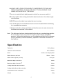
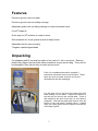
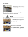
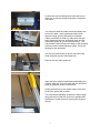
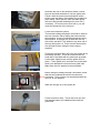
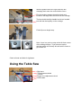
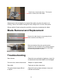
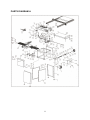
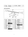
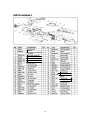
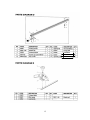
8” TABLE SAW
OPERATING INSTRUCTIONS
MODEL: W619
Charnwood, Cedar Court, Walker Road,
Bardon, Leicestershire, LE67 1TU
Tel. 01530 516 926 Fax. 01530 516 929
email; [email protected] website; www.charnwood.net
GENERAL SAFETY RULES
WARNING: Do not attempt to operate the machine until you have read thoroughly
and understood completely all instructions, rules, etc. contained in this manual.
Failure to comply may result in accidents involving fire, electric shock, or serious
personal injury. Keep this owner's manual and review frequently for continuous safe
operation.
1.Know your machine. For your own safety, read the owner's manual
carefully. Learn its application and limitations, as well as specific
potential hazards pertinent to this machine.
2.Make sure all tools are properly earthed.
3.Keep guards in place and in working order. If a guard must be
removed for maintenance or cleaning, make sure it is properly
replaced before using the machine again.
4.Remove adjusting keys and spanners. Form a habit of checking to see
that the keys and adjusting spanners are removed from the machine
before switched it on.
5.Keep your work area clean. Cluttered areas and workbenches increase
the chance of an accident.'
6.Do not use in dangerous environments. Do not use power tools in damp
or wet locations, or expose them to rain. Keep work areas well
illuminated.
7.Keep children away. All visitors should be kept a safe distance
8.from the work area.
9.Make workshop childproof. Use padlocks, master switches
remove starter keys.
and
10.Do not force the machine. It will do the job better and be safer at
the rate for which it is designed.
11.Use the right tools. Do not force the machine or attachments to do a job
for which they are not designed. Contact the manufacturer or distributor
if there is any question about the machine's suitability for a particular
task.
2
12.Wear proper apparel. Avoid loose clothing, gloves, ties, rings, bracelets,
and jewellery which could get caught in moving parts. Non-slip footwear is
recommended. Wear protective hair covering to contain long hair.
13.Always use safety glasses. Normal spectacles only have impact resistant
lenses. They are not safety glasses.
14.Do not over-reach. Keep proper footing and balance at all times.
15.Maintain the machine in good condition. Keep the machine clean for best and
safest performance. Follow instructions for lubrication and changing
accessories.
16.Disconnect the machine from power source before servicing and when
changing the blade.
17.Never leave the machine running unattended. Turn the power off. Do not
leave the machine until it comes to a complete stop.
18.Do not use any power tools while under the effects of drugs, alcohol or
medication.
19.Always wear a face or dust mask if operation creates a lot of dust and/or
chips. Always operate the tool in a well ventilated area and provide for proper
dust removal. Use a suitable dust extractor.
ADDITIONAL RULES FOR CIRCULAR
SAWS
1.Ensure that the saw table is clear of off-cuts, tools or anything else that might
foul the work-piece.
2.If your saw has a dust extractor hose connected to the crown guard, ensure
that it is held clear of the table and will not foul the work-piece as it passes
over the table.
3.When cutting large sheets of material or long boards use one or more roller
stand(s) to support the work or have a competent helper to support it as it
feeds off the rear of the table.
4.Never use the saw without the riving knife and check that it is in line with the
blade before using the saw.
5.Always use a brush to clear the table of dust or debris. NEVER use your
hands, especially when the machine is running.
3
6.ALWAYS USE A PUSH STICK WHEN IT IS NECESSARY TO PUSH ANY
PIECE OF MATERIAL OF SUCH SIZE THAT IT WOULD BRING YOUR
HANDS WITHIN 30 CM OF THE BLADE.
7.Do not cut material that is badly warped or which has screws or nails in it
8.Be extra vigilant when cutting stock which has loose knots in it as these my fly
out of the saw.
9.NEVER remove the table insert when the saw is running.
10.To avoid exposure to hazardous dust, do not use this saw without connecting
it to a suitable dust extractor.
11.Always work with a sharp saw blade and feed the work at a rate suites to the
thickness and hardness of the material.
Note: This table saw has been designed and built solely as a woodworking machine.
Do not modify it in any way or use for anything other than its designated
purpose. Neither the manufactures nor the supplies are liable for any damage
or injury caused by incorrect assembly, operation or electrical connection of
this machine.
Specification
Table size
535 x400mm
Table size with extensions
535 x 1000mm
Motor
1100W, 240v single phase
Blade diameter and bore
200mm 30mm
Blade rotation speed (no load)
4700 rpm
Maximum depth of cut at 90o
60mm
Maximum depth of cut at 45o
40mm
Cutting width with table extension
750mm
Cutting width without table extension
150mm
Dust extractor hose connection
100mm
Weight
45kg
4
Features
Precision ground, cast iron table
Precision ground cast iron sliding carriage
Adjustable guide hells on sliding carriage to ensure accurate travel
0 to 45o blade tilt
Quick stop for 90o position of crosscut fence
Dust extraction for crown guard as well as body of saw
Adjustable feet for easy levelling
Tungsten carbide tipped blade
Unpacking
Cut strapping and lift top and four sides of the crate off - all in one piece. Remove
plastic bag, support the two black table extensions as you remove bag. They will not
be damaged if they fall but they do make a loud noise!
Pack 2 is a cardboard box which contains 5
aluminium extrusions and one nut and bolt. These
latter are loose so make sure that you do not
discard them with the packaging.
Lay the saw over on its front and remove the two
bolts holding it to the pallet. Support the bottom of
the saw as you remove the second bold. There is
little weight at this end of the saw, so one hand is
adequate. Discard the pallet and remove from the
interior of the saw base 2 flexible tubes, 3 jubilee
clips, the crown guard, the tube support, the reducer
and a bag of parts.
5
Assembly
While the machine is on its side, take the four feet
from the bag of parts and screw them into the four
holes in the base. These feet can be adjusted by
means of a spanner so that saw table is level after
the machine has been put in place.
Return the saw to a vertical position.
The cast iron table is coated with a layer of grease to prevent rust. This is easily
removed with a soft cloth moistened with paraffin or WD40.
Warning
Do not use petrol, thinners or paint stripper to remove grease as these substances
may damage the paint finish.
Raise the blade with the hand wheel at the front of
the machine. Fit the handwheel from the bag of
components to the spindle on the R/H side of the
saw, tighten the grubscrew and turn the wheel until
the blade is vertical
Check that the riving knife is correctly aligned with the blade and then fit the crown guard to
the top of it and tighten the self locking nut with a 10 mm socket (not supplied).
There are two brackets at the front of the saw table
and a similar pair at the back. Each one has two
hex headed bolts and nuts passing through it and a
small black adjuster at the back
6
Loosen the nuts and lifting each bolt head in turn,
slide one of the two longest aluminium extrusions
over them
The extrusion with the scale should be fitted to the
front of the table, scale uppermost and in both
cases the wide groove should face outwards.
If they are difficult to slide on, make sure that you
have slackened the nuts sufficiently and rock the
extrusions gently as you move them along. You
may need to reach round to the back of the brackets
and unscrew the black adjusters a little, if they are
binding on the aluminium.
Join the two parts of the rip fence using one cap
head setscrew and one hex head bolt.
Place it over the front guide rail.
Align the fence with the saw blade and holding it in
position, align the 0 on the scale with the left hand
edge of the black portion of the fence.
Having done this you can tighten up the nuts thus
locking the guide rails in place.
The small black adjusting screws are used to align
the guide rails so that the rip fence is parallel with
the blade no matter where it is along the length of
the rail.
7
Now take the first of the extension tables, loosen
the nuts and bolts and slide it onto the guide rails.
Follow it with the second one and tighten all the
locking nuts and bolts. If the tables do not slide into
place easily, check that the front and back guide
rails are really parallel and adjust the rear one if
necessary. Do not move the front rail or you will
upset the alignment of the rip fence.
Fit the dust collection system.
The bracket holding the plastic connector is fitted to
the rear extrusion rail by sliding the bolt head into
the extrusion. It can be positioned anywhere along
the extrusion. A support arm is fitted into the top
side of the extrusion. This holds the top hose out of
the way during the cut. There are two hoses which
are secured in place using the hose clamps
supplied.
Fit the two brackets which will carry the guide rail for
the sliding carriage. These are bolted to the left
hand side of the table with the setscrews provided.
Leave them slightly loose until the guide rail is in
place. Fit the guide rail in a similar way to that with
which you attached the front and rear guide rails.
Make sure that it is parallel to the saw blade
Before fitting the sliding carriage it should be noted
that the two outboard wheels are mounted on
eccentrics. Their position can be adjusted with the
aid of a 14 mm spanner.
Slide the carriage on to the guide rail.
Fit the front travel stop. This is the loose nut and
bolt that that was in the cardboard box with the
guide rails.
8
With the plastic end to the right, slide the two
clamping block onto the crosscut/mitre fence.
The Work clamp passes though its block and
locates in the large hole at the front of the carriage.
The block with the Kipp handle has its tee headed
bolt slid into the keyway on the carriage.
Fit the flip-over length stop
Note: there is a push up stop at the left front corner
of the sliding carriage. If you have set up the
carriage guide rail correctly this will set the fence to
give a 90o cut.
Check all nuts and bolts for tightness.
Using the Table Saw
Rip fence
Tilt adjustment wheel
Tilt lock
Depth of cut adjustment wheel
NVR switch
9
Small cross cut and mitre fence. This may be
used on either side of the blade.
Adjustments to tilt and depth of cut should be made only when the saw is not
running. Never force timber through the saw, always let it cut at its own speed.
Always switch off and unplug the saw before removing or replacing the blade.
Blade Removal and Replacement
Remove the table insert by unscrewing the two
black setscrews and lifting it off.
Block the blade by fitting the special spanner
supplied over the shoulders of the clamping washer.
Unscrew the hex head bolt and remove the blade.
Reverse this procedure to refit it.
Troubleshooting
Saw vibrates
Check all nuts and bolts for tightness, check tilt
is locked and check that blade is not damaged.
Cuts are slow, wood is blackened
Sharpen or replace blade.
Saw stalls
Feed rate too high, slow down.
Tilt and/or blade height difficult
to adjust
Check tilt lock has been released, clean and
lubricate mechanism.
10
PARTS DIAGRAM A
11
Circlip
Rail support bracket
Angle bracket
12
Eccentric nut
Hand grip
Plastic moulding
Threaded spindle
13
Washer
V belt
Circlip
Circlip
Circlip
Riving knife
14
Rubber washer
Washer
15
L
N
Earth
NVR switch
16