1
Si5351A/B/C-B
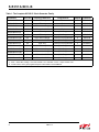
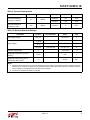
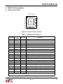
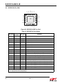
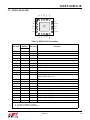
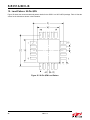
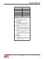
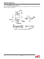
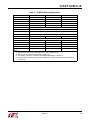
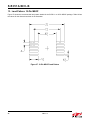
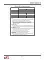
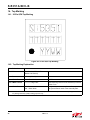
Table 18. PCB Land Pattern Dimensions
Symbol
Millimeters
Min
Max
C1
4.40 REF
E
0.50 BSC
G1
3.00
—
X1
—
0.30
Y1
Z1
1.40 REF
—
5.80
Notes:
General
1. All dimensions shown are in millimeters (mm) unless otherwise noted.
2. Dimensioning and Tolerancing per ASME Y14.5M-1994.
3. This Land Pattern Design is based on the IPC-7351 guidelines.
4. All dimensions shown are at Maximum Material Condition (MMC). Least
Material Condition (LMC) is calculated based on a Fabrication
Allowance of 0.05mm.
Solder Mask Design
5. All metal pads are to be non-solder mask defined (NSMD). Clearance
between the solder mask and the metal pad is to be 60 µm minimum, all
the way around the pad.
Stencil Design
6. A stainless steel, laser-cut and electro-polished stencil with trapezoidal
walls should be used to assure good solder paste release.
7. The stencil thickness should be 0.125 mm (5 mils).
8. The ratio of stencil aperture to land pad size should be 1:1.
Card Assembly
9. A No-Clean, Type-3 solder paste is recommended.
10. The recommended card reflow profile is per the JEDEC/IPC J-STD020C specification for Small Body components.
Rev. 1.0
37