1
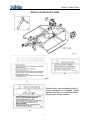
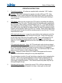
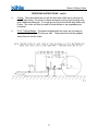
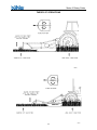
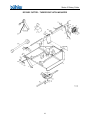
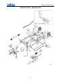
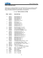
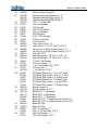
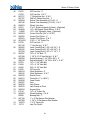
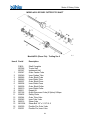
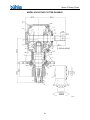
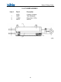
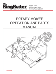
Series II Rotary Cutter
TABLE OF CONTENTS
DESCRIPTION
PAGE
WARRANTY................................................................ 1
INTRODUCTION ......................................................... 2
SAFETY....................................................................... 3
Safety................................................................ 3
General Safety .................................................. 4
Start Up Safety.................................................. 4
Operation Safety ............................................... 4
Transport Safety................................................ 5
Service & Maintenance Safety .......................... 5
Storage Safety .................................................. 5
Safety Signs ...................................................... 6
Safety Sign Installation...................................... 6
ASSEMBLY................................................................. 8
3 Point Hitch Mounted Assembly Instructions ... 8
Trailing Model Assembly Instructions................ 9
Chain Kit Assembly Instructions........................ 10
OPERATION ............................................................... 11
Operating Instructions ....................................... 11
Theory of Operation .......................................... 13
MAINTENANCE .......................................................... 14
Service .............................................................. 14
Bolt Torque ....................................................... 15
PARTS LISTS
3 Point Hitch Mounted Drawing......................... 16
Trailing Drawing ................................................ 17
Parts List ........................................................... 18
Chain Kit Drawing ............................................. 22
Chain Kit Parts List............................................ 23
Model #510 PTO Shaft Drawing & Parts List .... 24
Model #510 Shear Pin parts List ....................... 25
Model #620 & #720 PTO Shaft Drawing ........... 26
Model #620 – 3 Point Hitch Parts List ............... 27
Model #620 – Trailing Parts List........................ 28
Model #720 – 3 Point Hitch Parts List ............... 29
Model #720 PTO Shaft Drawing........................ 30
Model #720 – Trailing Parts List........................ 31
Model #720 Q-Shaft Drawing ............................ 32
Model #720 Q-Shaft Parts List .......................... 33
Series II Rotary Cutter
GEARBOXES
Model #510 Gearbox Drawing .......................... 34
Model #510 Gearbox Parts List......................... 35
Model #620 Gearbox Drawing .......................... 36
Model #620 Gearbox Parts List......................... 37
Model #720 Gearbox Drawing .......................... 38
Model #720 Gearbox Parts List......................... 39
CYLINDER ASSEMBLY DRAWING & PARTS LIST.. 40
SHIPPING KIT AND BUNDLE NUMBERS ................. 41
Series II Rotary Cutter
WARRANTY POLICY
Buhler Manufacturing products are warranted for a period of twelve (12) months (90 days for
commercial application) from original date of purchase, by original purchaser, to be free from
defects in material and workmanship under correct, normal agricultural use and proper
applications.
Buhler Manufacturing’s obligations under this warranty shall be limited to the repair or
exchange, at Buhler Manufacturing’s option, of any Buhler Manufacturing product or part which
proves to be defective as provided. Buhler Manufacturing reserves the right to either inspect
the product at the buyer’s location or have it returned to the factory for inspection.
The above warranty does not extend to goods damaged or subject to accident, abuse or misuse
after shipment from Buhler Manufacturing’s factory, nor to goods altered or repaired by anyone
other than an authorized Buhler Manufacturing representative.
Buhler Manufacturing makes no Express Warranties other than those, which are specifically
described. Any description of goods, including any references and specifications in catalogues,
circulars and other written material published, is for the sole purpose of identifying goods and
shall conform to such descriptions. Any sample or model is for illustrative purposes only and
does not create an Express Warranty that the goods conform to sample or model shown.
The purchaser is solely responsible for determining suitability of goods sold. This warranty is
expressly in lieu of all other warranties expressed or implied. Buhler Manufacturing will in no
event be liable for any incidental or consequential damages whatsoever. Nor for any sum in
excess of the price received for the goods for which liability is claimed.
WARRANTY CLAIMS:
Warranty requests must be prepared on Buhler Manufacturing Warranty Claim Forms with all
requested information properly completed. Warranty Claims must be submitted within a thirty
(30) day period from date of failure repair.
WARRANTY LABOR:
Any labor subject to warranty must be authorized by Buhler Manufacturing. The labor rate for
replacing defective parts, where applicable, will be credited at 100% of the dealer’s posted shop
rate. Defective parts will receive an extra 10% discount to assist with freight or other incidental
costs.
GOVERNMENT LEGISLATION:
Warranty terms and conditions are subject to Provincial or State legislation.
IMPORTANT FACTS:
Buckets and Bucket Tines Carry No Warranty
Bent Spears Carry No Warranty
Snowblower Fan Shafts Carry No Warranty
Mower Blades Carry No Warranty
Portable Auger Parts Have Two (2) Year Warranty
Loader Parts Have Two (2) Year Warranty
IMPORTANT NOTE: This warranty does not apply to rentals
1
Series II Rotary Cutter
INTRODUCTION
The Buhler Farm King Series II Rotary cutter available in 60”, 72” and 84” and are
equipped with either trailing style or 3-point hitch. The 3-point hitch is Buhler Quick
Hitch compatible so it is easy to attach and unhook. 3-point hitch models include a
single solid rubber training wheel, while rotary cutters with a trailing hitch have two
wheels, either air-filled or made of solid rubber.
Buhler Farm King Rotary Cutters are built tough and made to last. The blades are heattreated to enhance rigidity and the heavy-duty gearbox is designed to be rugged and
durable. The access panel on the deck makes it easy to inspect or replace the blades.
An optional chain kit minimizes the possibility of flying debris. The stump-jumper is a
24” plate mounted to the blades below the gearbox and minimizes stress on the deck
and gearbox. The power take-off (PTO) shaft on the Series II 60” Rotary Cutter
includes a sheer pin to protect the gearbox in the event of an unforeseen obstacle, while
the 72” and 84” rotary cutters are equipped with a slip clutch to prevent gearbox
damage. The Y720T with the trailing style hitch includes a two-piece PTO shaft for
tighter turning radius. An 8” cylinder and hoses are optional for all trailing models.
Keep this manual handy for frequent reference. All new operators or owners must
review the manual before using the equipment and at least annually thereafter. Contact
your Buhler Dealer if you need assistance, information, or additional copies of the
manual. Visit our website at www.buhler.com for a complete list of dealers in your area.
The directions left, right, front and rear, as mentioned throughout this manual, are as
seen facing in the direction of travel of the implement.
2
Series II Rotary Cutter
SAFETY
Remember, YOU are the key to safety. Good safety practices not only protect you, but
also the people around you. Make these practices a working part of your safety
program. Be certain that everyone operating this equipment is familiar with the
recommended operating and maintenance procedures and follows all the safety
precautions. Most accidents can be prevented. Do not risk injury or death by ignoring
good safety practices.
The alert symbol is used throughout this manual. It indicates attention is required and
identifies hazards. Follow the recommended precautions.
The safety alert symbol means…
ATTENTION! BECOME ALERT! YOUR SAFETY IS INVOLVED!
CAUTION
The caution symbol indicates a potentially hazardous situation that, if not
avoided, may result in minor or moderate injury. It may also be used to
alert against unsafe practices.
WARNING
The Warning Symbol indicates a potentially hazardous situation that, if
not avoided, could result in death or serious injury, and includes hazards
that are exposed when guards are removed. It may also be used to alert
against unsafe practices.
DANGER
The Danger Symbol indicates an imminently hazardous situation that, if
not avoided will result in death or serious injury. This signal word is to be
limited to the most extreme situations, typically for machine components
that, for functional purposes, cannot be guarded.
3
Series II Rotary Cutter
GENERAL SAFETY INSTRUCTIONS
Have a first-aid kit available for use and know how to use it.
Have a fire extinguisher available, stored in a highly visible location, and know how to
use it.
Wear appropriate protective gear. This list may include but is not limited to:
- hard hat
- protective shoes with slip resistant soles
- protective glasses or goggles
- heavy gloves
- wet weather gear
- hearing protection
- respirator or filter mask
Read and understand the Operator’s Manual and all safety signs before operating,
servicing, adjusting, repairing, or unplugging the equipment.
Do not attempt any unauthorized modifications to your Buhler product as this could
affect function or safety, and could affect the life of the equipment.
Never start or operate the cutter except from the operator’s station on the power unit.
Inspect and clean the working area before operating.
Keep hands, feet clothing, and hair away from moving parts.
Ensure bystanders are clear of the area before operating.
START UP SAFETY
Do not let inexperienced operators or children run this equipment.
Place all tractor and machine controls in neutral before starting.
Operate only with ROPS and seatbelt equipped tractors.
Do not operate inside a building unless there is adequate ventilation.
Ensure all shields are in place and in good condition before operating.
Stay clear of PTO shaft and machine when engaging PTO.
OPERATION SAFETY
Do not permit riders.
Do not wear loose fitting clothing during operation.
Never operate over 540 rpm PTO speed.
Never operate the equipment in the raised position.
4
Series II Rotary Cutter
TRANSPORT SAFETY
Review Transport Safety instructions in tractor manual before moving.
Check with local authorities regarding transport on public roads. Obey all applicable
laws and regulations.
Do not tow equipment that does not have brakes at speeds over 32 km/h (20 mp/h)
Do not two equipment that does not have brakes that, when fully loaded, has a mass
(weight) over 1.5 t (3300 lb.) and more than 1.5 times the mass (weight) of the towing
unit.
Make sure the SMV (Slow Moving Vehicle) emblem and all the lights and reflectors that
are required by the local highway and transport authorities are in place, are clean, and
can be seen clearly by all overtaking and oncoming traffic.
Never have the equipment in operation during transport.
Always travel at a safe speed.
SERVICE AND MAINTENANCE SAFETY
Stop engine, set brake, remove ignition key, and wait for all moving parts to stop before
servicing, adjusting, repairing, or unplugging.
Support the equipment with blocks or safety stands before working beneath it.
Follow good shop practices including:
- keep service area clean and dry
- be sure electrical outlets and tools are properly grounded
- use adequate light for the job
Use only tools, jacks, and hoists of sufficient capacity for the job.
Replace and secure all shields removed during serving before operating.
Use heavy leather gloves to handle sharp objects.
Check hydraulics regularly for leaks. Use cardboard to look for leaks, and use hand
and eye protection.
Relieve pressure on hydraulic system before repairing or adjusting.
STORAGE SAFETY
Store the unit in an area away from human activity.
Do not permit children to play on or around the stored machine.
Support the frame on stands and blocks to provide a secure base.
5
Series II Rotary Cutter
SAFETY SIGNS
The following illustration shows the approximate location and detail of safety signs.
Keep all safety signs clean and legible and replace any that are damaged or missing.
When original parts are replaced, any safety signs affixed to those parts should be
replaced as well. Replacement safety signs are available from your local dealer.
INSTALLATION OF SAFETY SIGNS
To install safety signs, ensure the installation area is clean and dry. Decide on the
exact position before you remove the backing paper. Remove the smallest portion of
the split backing paper and align over the specified area. Carefully press in place.
Slowly peel back the remaining paper and smooth the remaining portion in place. Small
air pockets can be pierced with a pin and smoothed out.
6
Series II Rotary Cutter
ROTARY CUTTER SAFETY SIGNS
#3
#1
Replace safety sign immediately should it
become damaged, torn or illegible. Obtain
replacements from your authorized dealer
using the part numbers shown.
#2
7
Series II Rotary Cutter
ASSEMBLY INSTRUCTIONS
Three point hitch mounted models:
1.
Mount the hitch assembly (#7) to the deck using the category 1 lift arm pins (#32)
supplied. The bushings (#34), and the 1" I.D. washer (#73) should allow the
hitch to swivel freely.
2.
The ends of the two pivot arms (#5 & #6) with the offset holes bolt to the hitch
using a 5/8" x 4" bolt and lock nut. The offset should be turned down. The lift
arm (#4) bolts between the ends of the pivot arms and the brackets at the top of
the center mount (#2) using 5/8" x 2" hex bolts and lock nuts. Do not over tighten
the lock nuts. The entire hitch assembly should swivel freely if properly
assembled. Assemble chain PTO holder (#104) to 3-point hitch (#7) using one
3/8” x 1 ½” hex bolt (#103), lock washer and hex nut.
2.
Bolt the tail wheel arm (#8) to the center mount (#2) using a 5/8" x 4" bolt and
lock nut. The tube welded to the outside end of the tail wheel arm is offset
2 ¼” past the edge of the tube. The 2 ¼” offset is turned down for 5’ and 6’
cutters and up for 7’ cutters. Assemble the tail wheel (#11) in the wheel yoke
(#10) using axle pin (#12) and a ¼” x 1 ½” cotter pin. Mount the yoke in the
sleeve at the end of the tail wheel arm. Use an 18 gauge washer on each side of
the sleeve and lock in place with a ¼” x 1 ¾” cotter pin. The adjustment arms
(#9) hold the tail wheel arm in place and also set the cutting height of the cutter.
Bolt arms to the deck using hex bolts (#15) and lock nuts and to the tail-wheel
arm using 5/8" x 4" hex bolt and lock nut.
4.
Connect the PTO shaft to the gearbox. A snap ring holds on the PTO shafts with
a shear pin. The clutch must be engaged on PTO shafts with a slip clutch as per
operating instructions so the clutch will slip if you hit a hard object. After
engaging clutch, bolt the PTO guard (#3) to the center mount using 5/16" x ¾”
hex bolts, lock washers and hex nuts.
5.
Re-check all the fasteners. There should be free movement of all pieces held
together by a bolt and lock nut.
8
Series II Rotary Cutter
ASSEMBLY INSTRUCTIONS
Trailing Models:
1.
Mount the swivel tube assembly (#47) to the cutter deck by bolting to the outside
edge of the deck reinforcement using ½” x 1 ¾” hex bolts, lock washers and hex
nuts.
2.
The wheel yoke arms (#48) may be assembled to cutter in two ways:
a)
Wheels trailing behind mower. Assemble as shown in drawing. Bolt the
yoke arms (#48) to the tube assembly using ½” x 2" hex bolts, lock
washers and hex nuts with the wheels turned to the inside of the mower.
With the wheels in this position, the control rod clevis (#53) attaches to
the top bracket on the tube assembly as shown in drawing. Use a 1" I.D.
flat washer and a ¼” x 1 ½” cotter pin to mount the wheels.
b)
Wheels forward at side of cutter. Bolt the yoke arms to the tube assembly
so the wheels are on the outside of the cutter. With the wheels in this
position, the control rod clevis (#53) attaches to the bottom bracket on the
tube assembly.
3.
Bolt the tongue assembly (#63) to the cutter deck using 7/8" x 2 ½” bolts, lock
washers and hex nuts. The 1 ¼” diameter x 5/8" long bushings (#58) held in
place by a 1" I.D. flat washer (#73) should allow the tongue to swivel.
3.
An 8" stroke hydraulic cylinder (#49) is required to operate the hydraulic lift on
the cutter. Using ½” x 90º elbows (#50) on the hydraulic cylinder will keep the
hoses in better alignment (for 5’ & 6’). Approximately 12 foot long hydraulic
hoses are required.
4.
Bolt the welded end of the level control rod (#56) to the front tongue as shown on
drawing using a 5/8" x 2 ½” hex bolt and lock nut. The control rod clevis (#53)
must be adjusted so the cutter will sit level with the ground when it is pinned to
the swivel assembly.
Note: Be sure to use the top bracket on the swivel assembly (#47) when the
wheels are trailing behind the cutter as shown in drawing.
5.
Mount the slip clutch PTO shaft on the cutter. The clutch must be engaged so it
will slip when you hit a hard object as per operating instructions. After engaging
the clutch, bolt on the PTO guard (#3) using 5/16" x ¾” hex bolts, lock washers
and hex nuts.
7.
An optional jack (#67) is available to lift the tongue when mounting the cutter on
a tractor.
9
Series II Rotary Cutter
ASSEMBLY INSTRUCTIONS - CONT'D.
Trailing Models:
8.
9.
Re-check and tighten all bolts. Only pieces held by a bolt and lock nut should
have free movement.
7’ Cutters Only: Bolt the PTO bearing stand (#76) to the edge of the deck using
5/8” x 1 ¾” hex bolts, lock washers and hex nut. Mount the PTO Q-shaft on the
cutter gearbox. Slide a 1 3/8” pillow bearing onto the shaft at the end of the Qshaft. With the guard mount (#77) under the pillow bearing, bolt the pillow block
to the stand using 5/8” x 2 ¼” hex bolts, lock washers and hex nuts. Connect the
second PTO shaft to the splined end of the Q-shaft. Bolt the PTO guard (#78) to
the stand using ¼” x ½” hex bolts, lock washers and hex nuts.
CHAIN KIT - ASSEMBLY INSTRUCTIONS
All cutters have the required holes for mounting the chain kit. The use of this chain kit
will help reduce the possibility of injury to persons or property by stopping many thrown
objects.
1.
Bolt the front chain holder (#1) to the front of the cutter using ½” x 1" hex bolts,
lock washers and hex nuts.
2.
Use ¼” x 6 link chains (#7) at the front. A chain is pushed through each slot from
underneath and a 3/8" rod is threaded through the top link of each chain. Hold
rods in place using the cotter pins supplied. See parts list for correct length of
rods.
3.
Bolt the rear center (#3) and rear side (#14) chain holder to the rear of the cutter.
Use ¼” x 5 link chains (#8) along all rear edges. Thread rods as in front using
lengths as shown in parts list.
NOTE: Washers are used to hold an extra chain at both ends of the rear center
rod and at the inside end only of the rear side rods. These extra chains close the
gap left at the corners where the chain holders meet.
10
Series II Rotary Cutter
OPERATING INSTRUCTIONS
1.
Connecting to tractor: All cutters are supplied with a standard 1 3/8" 6-spline
yoke on the PTO shaft.
Warning: This cutter is designed to operate only with a 540 rpm PTO. After
connecting cutter to tractor and before doing any cutting, check to see that the
PTO shaft is not touching anywhere on the cutter when raising and lowering or
when cornering.
2.
PTO Shafts: Make sure the length of the PTO shaft is compatible with different
working positions of the cutter. Carefully follow the lubrication chart supplied with
the PTO shaft. When cutting, avoid joint angles over 35º. PTO shafts should be
disengaged when turning sharp corners. Using tape or a bright colored marking
pen, mark on the outer shields the position where the shaft is completely pushed
together and the position where you have a 4" overlap. Watch these marks when
moving the cutter through all possible operating angles to see that the PTO shaft
stays within this range.
PTO shafts with shear pin - Loosen the outer shield on the implement end of the
PTO and push the gearbox shaft through the end yoke. Using snap ring pliers,
put the snap ring on the end of the gearbox shaft. This is what keeps the PTO
shaft on if the shear pin breaks and the cutter should not be used without it.
Insert a ½” x 3 ½” Grade 2 bolt with a lock nut to act as shear pin and replace all
shields.
PTO shafts with slip clutch - Note: All PTO shafts with a slip clutch are shipped
with the slip clutch disengaged. There are four socket set screws on the inside of
the clutch assembly which are all turned out as far as they go to engage the
clutch. Disengage by turning set screws in fully. The clutch should slip if a hard
object such as a stump or rock is hit by the blades.
Caution: Always be certain that the PTO shaft is disengaged and the tractor
brakes are locked before making this or any other adjustment.
The clutch plates should be "burned" just before using the cutter in spring for the
first time. This is done by disengaging the clutch and then engaging the PTO
shaft for a few seconds till the clutch plates smoke. After this you engage the
clutch again as described above. This is done because the plates may lock up
during prolonged storage.
3.
Operating tractor engine: Operate the tractor PTO at 540 rpm when doing
normal cutting. If the forward speed is too high, a lower gear can be used.
11
Series II Rotary Cutter
OPERATING INSTRUCTIONS – cont’d.
4.
Cutting: The cutter should be run with the front end a little low or just level for
normal light cutting. For brush or dense tall weeds, running front end high may
give a better shredding job. On rough ground, the front end will also tend to dig
in less. The cutter can also be used to shred stubble or top vegetables prior
to harvest.
5.
5’ & 6’ Trailing Models: The wheels supplied with the cutter are for towing at
speeds of no more than 20 miles per hour. These wheels should be greased
every time you use the cutter.
12
Series II Rotary Cutter
THEORY OF OPERATIONS
13
Series II Rotary Cutter
MAINTENANCE
SERVICING INSTRUCTIONS
LUBRICATION
1.
Gearbox: The gearbox should be filled with SAE90 oil to the bottom edge of the
lower oil plug when shipped. Check this before using the cutter and at regular
intervals to see that this oil level is maintained.
6.
Grease wheels, tail wheel spindle sleeve, universal joints and shield bushings on
the PTO shaft after every eight hours of use. Lubricate the telescoping PTO tube
and the PTO quick release about every twenty
hours of use.
3.
Shielding: Always keep all shielding in place and repair or replace if damaged.
4.
Blades: When replacing or grinding the cutting blades, both blades must be
replaced or reground at the same time to maintain the proper balance in the
cutting unit.
IMPORTANT: Use Buhler replacement blades only. Using substitute blades
may be dangerous. When changing blades, open the access door on the deck
and take the screws out of the blade pin clips. The clips are then pulled out and
the blade should fall down. Replacing the new or sharpened blades is done with
the back of the mower raised and securely blocked so it will not fall. Bolt on the
blade pin clips and close the access door.
5.
PTO Shaft: To replace clutch lining on slip clutch PTO shafts, first disengage the
clutch by turning the four set screws all the way in. Remove outside bolts from
clutch assembly and replace clutch linings. When re-tightening bolts, stop when
the clutch spacer starts to touch the clutch plates. You should be able to just
move the spacer by hand when you have the correct bolt torque. Re-engage
clutch after assembly is complete.
14
Series II Rotary Cutter
15
Series II Rotary Cutter
ROTARY CUTTER – THREE POINT HITCH MOUNTED
16
Series II Rotary Cutter
ROTARY CUTTER – TRAILING TYPE
17
Series II Rotary Cutter
WHEN ORDERING PARTS
Always give your dealer the Model, Color and Serial Number of your machine to assist
him in ordering and obtaining the correct parts. Use the exploded view and tabular
listing of the area of interest to exactly identify the required part.
5', 6', & 7' SER 2 ROTARY CUTTER
ITEM
PART #
DESCRIPTION
1
906417
906419
906420
906426
906372
966502
966102
906424
906425
906382
906380
906381
906389
906390
966582
966144
905143
966508
966105
902318
966583
966145
905147
910032
966510
905145
966511
9812434
967110
84270
84299
812482
81671
84299
86170
Deck Weldment - 5'
Deck Weldment - 6'
Deck Weldment - 7'
Center Mount - 5'
Center Mount - 6' & 7'
PTO Guard - 5'
PTO Guard - 6' & 7'
Lift Arm (25 1/4'') - 5'
Lift Arm (32 1/2'') - 6'
Lift Arm (38 1/4'') - 7'
Pivot Arm (Left) - 5', 6', & 7'
Pivot Arm (Right) - 5', 6', & 7'
A-Frame Hitch Weldment - 5'
A-Frame Hitch Weldment - 6' & 7'
Tail Wheel Arm (48'') - 5'
Tail Wheel Arm (54 1/2'') - 6'
Tail Wheel Arm (63'') - 7'
Adjustment Arm (22 1/8'') - 5'
Adjustment Arm (24 1/2'') - 6'
Adjustment Arm (22 1/8'') - 7'
Rear Wheel Yoke - 5'
Rear Wheel Yoke - 6'
Rear Wheel Yoke - 7'
16" Rubber Sectional Wheel - 5' & 6'
16'' Solid Rubber Wheel - 5' & 6'
20 1/2'' Solid Rubber Wheel W/ Brg. - 7'
Axle Pin (1'' x 7'')
1/4'' x 1 1/2'' Cotter Pin
1 1/4'' ID x 14 Ga Narrow Rim Washer
5/8'' x 1 3/4'' Hex Bolt - 5' & 6'
5/8'' x 2'' Hex Bolt - 7'
5/8'' Lock Nut
5/8'' x 4'' Hex Bolt
5/8'' x 2'' Hex Bolt
3/8'' x 1'' Hex Bolt
2
3
4
5
6
7
8
9
10
11
12
13
14
15
16
17
18
19
18
Series II Rotary Cutter
20
21
22
23
24
25
26
27
28
29
30
31
32
33
34
35
36
37
38
39
40
41
42
43
44
966562
966108
966109
966194
81620
81637
81636
84000
81593
84217
81549
81569
81568
965807
965910
965809
965926
965911
906416
906418
84522
81723
981765
81722
907310
F0438
F0440
F0441
F0439
F0442
F0443
966518
966110
966519
966111
966192
F9439
F9440
966520
966521
84299
81684
81677
81701
85mm x 50mm Cotter Pin
Gearbox Assembly (Shear Pin) - 5'
Gearbox Assembly (Slip Clutch) - 6'
Gearbox Assembly (Slip Clutch) - 7'
1/2'' x 1 1/4'' Hex Bolt
1/2'' Lock Washer
1/2'' Hex Nut
3/8'' ID Flat Washer
3/8'' Lock Washer
3/8'' Wing Nut
5/16'' x 3/4'' Hex Bolt
5/16'' Lock Washer
5/16'' Hex Nut
Top Link Pin (Cat.1) - 5'
Top Link Pin 1'' x 5 1/4'' (Cat.2) - 6' & 7'
Lift Arm Pin w/ Nut & Washer (Cat.1) - 5'
Lift Arm Pin w/ Nut & Washer (Cat.2) - 6' & 7'
Linch Pin 7/16''
Swivel Bushing (1 1/4'' O.D. x 7/16'') - 5'
Swivel Bushing (1 1/2" OD x 9/16") - 6' & 7'
1'' S.A.E. Flat Washer
7/8'' Lock Washer - 5'
1 1/8'' Lock Washer (pl) - 6' & 7'
7/8'' Hex Nut - 5'
1 1/8" Hex Nut - 6' & 7'
PTO Shaft (Shear Pin) - 5' w/ 3 PT. Hitch
PTO Shaft (Slip Clutch) - 6' w/ 3 PT. Hitch
PTO Shaft (Slip Clutch) - 6' Trailing Type
PTO Shaft (Shear Pin) - 5' Trailing Type
PTO Shaft (Slip Clutch) - 7' w/ 3pt. Hitch
PTO Shaft (Slip Clutch) - 7' Trailing Type
Stump Jumper - 5'
Stump Jumper - 6' & 7'
Blade (24'') - 5' (Standard)
Blade (30'') - 6' (Standard)
Blade (36'') - 7'' (Standard)
Blade (24 1/4'') - 5' (Optional Low Cut) Set of 2
Blade (30 1/4'') - 6' (Optional Low Cut) Set of 2
Blade Pin Clip
Blade Pin Clip
5/8'' x 2'' Hex Bolt - 5'
3/4'' x 2 1/4'' Hex Bolt - 6' & 7'
5/8'' Lock Washer - 5'
3/4'' Lock Washer - 6' & 7'
19
Series II Rotary Cutter
45
46
47
48
49
50
51
52
53
54
55
56
57
58
59
60
61
62
63
64
65
66
67
68
69
70
71
72
73
74
75
81676
81700
967217
907157
966584
966146
966523
24791
964650
114905
966524
966525
902341
9812433
81700
967142
966526
906122
901756
966527
907308
966528
906418
87553
81684
84335
81592
906414
906415
966530
966531
964638
960327
966532
966533
966534
81210
966563
89598
967140
907309
103753
12779
5/8'' Hex Nut - 5'
3/4'' Hex Nut - 6' & 7'
1'' Slotted Hex Nut - 5' & 6'
30M x 2 Slotted Hex Nut - 7'
Swivel Tube Assembly (61 3/4'') - 5'
Swivel Tube Assembly (73 3/4'') - 6' & 7'
Wheel Yoke Arm
3'' x 8'' Stroke Hydraulic Cylinder - (Optional)
1/2'' x 90 Degree Street Elbow - 5' & 6'
1/2'' x 144'' Hydraulic Hose - (Optional)
Control Rod Pin (3/4'' x 2 5/16'')
Control Rod Clevis - 5'
Control Rod Clevis - 6' & 7'
3/16'' x 1 1/2'' Cotter Pin
3/4'' Hex Nut - 5'
1'' Hex Nut (pl) - 6' & 7'
Level Control Rod (1.24'' x 50 1/2'') - 5'
Level Control Rod (1.66'' x 59 1/4'') - 6'
Level Control Rod (1.66'' x 71 1/2'') - 7'
7/8'' x 2 1/2'' Bolt - 5'
1 1/8'' X 2 1/2'' Hex Bolt (pl) - 6' & 7'
Swivel Bushing (1 1/4'' OD x 5/8'') - 5'
Swivel Bushing (1 1/4'' OD x 9/16'') - 6' & 7'
1/2'' x 1 3/4'' Hex Bolt
1/2'' x 2 1/4'' Hex Bolt
5/8'' x 2 1/2'' Hex Bolt
3/8'' Hex Nut
Hitch Weldment - 5'
Hitch Weldment - 6' & 7'
Swivel Clevis
Clevis Pin (1'' x 4 9/16'')
Hose Clamp
Jack
Jack Clamp
Jack Clamp w/ Pivot
Access Door
1/4'' x 2'' Cotter Pin
Wheel Bushing - 5' & 6'
Bearing Ball - 7'
1'' x 10 Ga Narrow Rim Washer
1 1/8'' x 10 Ga Narrow Rim Washer
1'' X 4'' Clevis Pin
Hair Pin Clip #9
20
Series II Rotary Cutter
7' Rotary Cutter (Trailing) - PTO Kit
76
902348
PTO Stand Weld't
77
902549
PTO Guard Mount
78
902550
PTO Guard
79
81523
1/4'' x 1/2'' Hex Bolt
80
81545
1/4'' Lock Washer
81
81544
1/4'' Hex Nut
82
84270
5/8'' x 1 3/4'' Hex Bolt
83
981664
5/8'' x 2 1/4'' Hex Bolt
84
81677
5/8'' Lock Washer
85
812639
5/8'' Flat Washer
86
81676
Hex Nut
87
967490
1 3/8'' Pillow Baring
88
F9458
PTO W/Qshaft
Wheel Yoke Assembly
89
961891
Oil Seal CTD (SE11)
90
967712
Outer Bearing Cone (LM67048)
91
968405
Bearing Cup (LM11910)
92
105173
4-Bolt Hub (H411) w/ Cups CTD
93
967711
Outer Bearing Cup (LM67010)
94
968406
Outer Bearing Cone (LM11949)
95
9812416
Washer 3/4'' SAE (br)
96
3/4'' Slotted Hex Nut (br)
97
981309
1/8'' x 1 1/4'' Cotter Pin (br)
98
968409
Dust Cap (C12)
99
967900
Grease Fitting 1/4"
100
901051
Wheel Yoke 3/4'' x 4'' x 26''
F9434
Wheel Yoke Assembly c/w Hub
101
102
103
104
907475
909277
812026
811792
909703
Manual (FK324) w/ Holder
Manual Hldr.
5/16" x 1" Hex Bolt
3/8" x 1 1/2" Hex Bolt
23 Link Chain w/ Hook
21
Series II Rotary Cutter
OPTIONAL CHAIN KIT FOR ROTARY CUTTERS
22
Series II Rotary Cutter
ROTARY CUTTER - CHAIN KIT
ITEM
PART #
DESCRIPTION
1
966586
966147
966610
966587
966148
966611
966588
966149
966612
966589
966150
966613
966587
966151
966614
966590
966152
966615
966591
966596
81619
81637
81636
9812430
964001
966593
966594
966616
Front Chain Holder, 5' (60'' Long)
Front Chain Holder, 6' (72'' Long)
Front Chain Holder, 7' (84'' Long)
Front Chain Rod, 5' (3/8'' x 30 1/2'')
Front Chain Rod, 6' (3/8'' x 36 3/8'')
Front Chain Rod, 7' (3/8'' x 42'')
Rear Center Chain Holder, 5' (29'' Long)
Rear Center Chain Holder, 6' (32 1/4'' Long)
Rear Center Chain Holder, 7' (33 1/2'' Long)
R.H. Rear Side Chain Holder, 5' (23'' Long)
R.H. Rear Side Chain Holder, 6' (28'' Long)
R.H. Rear Side Chain Holder, 7' (37 1/4'' Long)
Rear Center Chain Rod, 5' (3/8'' x 30 1/2'')
Rear Center Chain Rod, 6' (3/8'' x 34'')
Rear Center Chain Rod, 7' (3/8'' x 33'')
Rear Side Chain Rods, 5' (3/8'' x 24'')
Rear Side Chain Rods, 6' (3/8'' x 28 7/8'')
Rear Side Chain Rods, 7' (3/8'' x 37'')
1/4'' x 6 Link Plated Chain (Front)
1/4'' x 5 Link Plated Chain (Rear)
1/2'' x 1'' Hex Bolt
1/2'' Lock Washer
1/2'' Hex Nut
1/8'' x 1'' Cotter Pin
7/16'' I.D. x 10 Ga x 1'' O.D. Flat Washer (pl)
L.H. Rear Side Chain Holder, 5' (23'' Long)
L.H. Rear Side Chain Holder, 6' (28'' Long)
L.H. Rear Side Chain Holder, 7' (37 1/4'' Long)
2
3
4
5
6
7
8
9
10
11
12
13
14
23
Series II Rotary Cutter
MODEL #510 ROTARY CUTTER PTO SHAFT
Model #510 (Shear Pin) - Trailing Ser 2
Item # Part #
1
2
3
4
5
6
7
8
9
10
11
12
13
14
15
16
17
F0439
907286
907287
936347
936349
966248
966249
966207
966208
966209
966210
966211
907186
936402
936344
936345
966216
9812034
936350
936351
Description
Shaft Complete
Tractor Half
Implement Half
Outer Cardan Tube
Inner Cardan Tube
Outer Shield Tube
Inner Shield Tube
Outer Shield Cone
Inner Shield Cone
Outer Shield Collar
Inner Shield Collar
Repair Kit
Quick Disconnect Yoke (6 Spline) 540rpm
Safety Chain
Outer Tube Yoke
Inner Tube Yoke
Shear Yoke
Shear Bolt 1/2" x 3 1/2" Gr 2
Flexible Pin, Outer Yoke
Flexible Pin, Inner Yoke
24
Series II Rotary Cutter
Model #510 (Shear Pin) - 3-Point Hitch Ser 2
Item # Part #
1
2
3
4
5
6
7
8
9
10
11
12
13
14
15
16
17
F0438
907292
907293
936346
936348
966205
966206
966207
966208
966209
966210
966211
907186
936402
936344
936345
966216
9812034
936350
936351
Description
Shaft Complete
Tractor Half
Implement Half
Outer Cardan Tube
Inner Cardan Tube
Outer Shield Tube
Inner Shield Tube
Outer Shield Cone
Inner Shield Cone
Outer Shield Collar
Inner Shield Collar
Repair Kit
Quick Disconnect Yoke (6 Spline) 540rpm
Safety Chain
Outer Tube Yoke
Inner Tube Yoke
Shear Yoke
Shear Bolt 1/2" x 3 1/2" Gr 2
Flexible Pin, Outer Yoke
Flexible Pin, Inner Yoke
25
Series II Rotary Cutter
MODEL #620 & #720 ROTARY CUTTER PTO SHAFT
26
Series II Rotary Cutter
Model #620 (Slip Clutch) 3-Point Hitch Ser 2
Item # Part #
1
2
3
4
5
6
7
8
9
10
11
12
13
16
17
18
19
20
21
22
23
24
25
26
27
28
F0440
907295
907296
936354
936356
966230
966231
966232
936518
966234
966235
966236
907294
936402
936352
936353
936517
936519
936512
936520
966223
936521
936523
910-075
936522
936526
936358
936359
908265
Description
Shaft Complete
Tractor Half
Implement Half
Outer Cardan Tube
Inner Cardan Tube
Outer Shield Tube
Inner Shield Tube
Outer Shield Cone
Inner Shield Cone
Outer Shield Collar
Inner Shield Collar
Repair Kit
Quick Disconnect Yoke (6-Spline) 540rpm
Safety Chain
Outer Tube Yoke
Inner Tube Yoke
Torque Limiter FT42R/6
Screw
Screw
Clutch Plate
Bushing
Lining
Hub
Pivot
Thrust Plate
Spacer
Flexible Pin, Outer Yoke
Flexible Pin, Inner Yoke
Spring
27
Series II Rotary Cutter
Model #620 (Slip Clutch) Trailing Ser 2
Item # Part #
1
2
3
4
5
6
7
8
9
10
11
12
13
16
17
18
19
20
21
22
23
24
25
26
27
28
F0441
907297
907298
936355
936357
966256
966257
966232
936518
966234
966235
966236
907294
936402
936352
936353
936517
936519
936512
936520
966223
936521
936523
910-075
936522
936526
936358
936359
908265
Description
Shaft Complete
Tractor Half
Implement Half
Outer Cardan Tube
Inner Cardan Tube
Outer Shield Tube
Inner Shield Tube
Outer Shield Cone
Inner Shield Cone
Outer Shield Collar
Inner Shield Collar
Repair Kit
Quick Disconnect Yoke (6-Spline) 540rpm
Safety Chain
Outer Tube Yoke
Inner Tube Yoke
Torque Limiter FT42R/6
Screw
Screw
Clutch Plate
Bushing
Lining
Hub
Pivot
Thrust Plate
Spacer
Flexible Pin, Outer Yoke
Flexible Pin, Inner Yoke
Spring
28
Series II Rotary Cutter
Model #720 (Slip Clutch) 3-Point Hitch Ser 2
Item #
1
2
3
4
5
6
7
8
9
10
11
12
13
16
17
18
19
20
21
22
23
24
25
26
27
28
Part #
Description
F0442
907300
907301
936442
936443
936445
936446
966232
936518
910-046
910-055
910-036
907299
936402
910-039
910-048
936528
936519
936512
936529
966223
936521
936523
910-075
936522
936526
910-040
910-042
936524
Shaft Complete
Tractor Half
Implement Half
Outer Cardan Tube
Inner Cardan Tube
Outer Shield Tube
Inner Shield Tube
Outer Shield Cone
Inner Shield Cone
Outer Shield Collar
Inner Shield Collar
Repair Kit
Quick Disconnect Yoke (6-Spline)
Safety Chain
Outer Tube Yoke
Inner Tube Yoke
Torque Limiter FT42/6
Screw
Screw
Clutch Plate
Bushing
Lining
Hub
Pivot
Thrust Plate
Spacer
Flexible Pin, Outer Yoke
Flexible Pin, Inner Yoke
Spring Set
29
Series II Rotary Cutter
#720 TRAILING ROTARY CUTTER PTO SHAFT
30
Series II Rotary Cutter
Model #720 (Slip Clutch) Trailing Ser 2
Item # Part #
1
2
3
4
5
6
7
8
9
10
11
12
13
14
15
16
F0443
907302
907303
936486
936487
936490
936491
966232
936492
910-046
910-055
910-036
907299
936402
910-039
910-048
936489
910-040
910-042
Description
Shaft Complete
Tractor Half
Implement Half
Outer Cardan Tube
Inner Cardan Tube
Outer Shield Tube
Inner Shield Tube
Outer Shield Cone
Inner Shield Cone
Outer Shield Bearing
Inner Shield Bearing
Repair Kit
Quick Disconnect Yoke (6-Spline) 540rpm
Safety Chain
Outer Tube Yoke
Inner Tube Yoke
Clamp Yoke (6 Spline)
Flexible Pin, Outer Yoke
Flexible Pin, Inner Yoke
31
Series II Rotary Cutter
MODEL #720 TRAILING ROTARY CUTTER Q-SHAFT
32
Series II Rotary Cutter
Model #720 (Q-Shaft w/Slip Clutch) - Trailing Ser 2
Item #
1
2
3
4
5
6
7
8
9
10
11
12
13
14
15
16
17
18
19
20
21
22
23
Part #
Description
F9458
936501
936561
910-036
910-039
910-040
936496
936497
936528
910-046
966232
936498
936499
936500
910-055
936402
936519
936512
936529
966223
936521
936523
910-075
936522
936526
936524
Shaft Complete
Tractor Half
Implement Half
Repair Kit
Outer Tube Yoke
Flexible Pin, Outer Yoke
Splined Shaft
Outer Tube
Torque Limiter FT42/6
Outer Shield Bearing
Outer Shield Cone
Outer Shield Tube
Inner Shield Tube
Inner Shield Collar
Inner Shield Bearing
Safety Chain
Clutch Screw
Set Screw
Clutch Plate
Antifriction Sleeve
Lining
Hub
Retaining Bolt
Thrust Plate
Spacer
Spring Set
33
Series II Rotary Cutter
MODEL #510 ROTARY CUTTER GEARBOX
34
Series II Rotary Cutter
Model #510 Gearbox Ser 1 & 2
Item #
Part #
Description
1
2
3
4
5
6
7
8
9
10
11
12
13
14
15
16
17
18
19
20
21
22
23
24
966108
914018
914006
914015
904022
904021
966824
966542
966555
914005
914013
914019
914007
914001
966562
86171
967217
904028
81593
914016
905429
914008
914003
966545
904023
Gearbox Assembly
Housing
Cap - Input
Cap - Output
Gear - Output, w/Shaft 15T
Gear - Input 22T
Shaft - Input 1 3/8"
Bearing - Ball 207K
Bearing - Ball 208K
Seal - Input 3LIP
Seal - Output 3LIP
Gasket - Output Cap
Gasket - Input Cap
Spacer
Cotter Pin 5 x 50
3/8" x 1 1/4" Hex Bolt
1" Slotted Hex Nut
Washer - Blade Hub 1"
3/8" Lockwasher
1/8" Sq Head Pipe Plug
1/2" Vent Plug
Retaining Ring Eaton 916R
Retaining Ring
Snap Ring
Blade Hub
35
Series II Rotary Cutter
MODEL #620 ROTARY CUTTER GEARBOX
36
Series II Rotary Cutter
Model #620 Gearbox
Item #
Part #
Description
1
2
3
4
5
6
7
8
9
10
11
12
13
14
15
16
17
18
19
20
21
22
23
24
25
26
27
28
29
30
31
32
33
34
966109
966825
966830
966832
966835
966828
966831
966833
966834
966846
966829
966838
966839
966840
906427
966837
966827
811927
81593
966841
966842
966843
966826
81657
812136
966836
906428
906429
906430
966844
906431
966866
904028
967217
966562
Gearbox Assembly
Housing
Output Shaft
Bearing Cone 368
Bearing Cup 362
Output Gear 13T
Input Shaft
Bearing Cone LM603049
Bearing Cup LM603014
Retaining Ring
Input Gear 19T
Input Cap Gasket 0.30mm
Input Cap Gasket 0.15mm
Input Cap Gasket 0.10mm
1/4" Pipe Plug
Input Seal
Input Cap
M10 X 30 Hex Bolt
3/8" Lockwasher
Output Cap Gasket 0.30mm
Output Cap Gasket 0.15mm
Output Cap Gasket 0.10mm
Output Cap
9/16" Lockwasher
14mm x 35mm Hex Bolt
Output Seal
Vent Plug .25''
Rivet
I.D. Tag
Spacer
Spacer
Blade Hub
1'' Blade Hub Washer
1'' Slotted Hex Nut
Cotter Pin 5mm x 50mm
37
Series II Rotary Cutter
MODEL #720 ROTARY CUTTER GEARBOX
38
Series II Rotary Cutter
Model #720 Gearbox
Item #
Part #
Description
1
2
3
4
5
6
7
8
9
10
11
12
13
14
15
16
17
18
19
20
21
22
23
24
25
26
27
966194
907157
966866
966867
966868
966869
966870
966874
966872
966873
967308
966871
966875
966876
966877
966878
966879
966880
966881
966882
966122
966883
966884
966885
966886
966887
81569
966888
Gearbox Assembly
Slotted Hex Nut M30 x 2
Blade Hub
Bolt M10 x 22
Seal 50 x 70 x 8
Output Shaft
Bevel Gear - 14 Tooth
Circlip
Split Pin 4 x 55
Housing
Taper Bearing Cone & Cup 30207
Circlip
Vent Plug 3/8"
Bevel Gear - 17 Tooth
Bolt M8 x 25
Taper Bearing Cone & Cup 30308
End Cap
Input Shaft
Double Lip Seal 40 x 70 x 8
O-Ring 3.1 x 155
Taper Bearing Cone & Cup 30210A
Sleeve
Output Cap
O-Ring 5 x 90
Split Pin 5 x 55
M10 Lockwasher
M8 Lockwasher (sub 5/16")
Level Plug
39
Series II Rotary Cutter
3 x 8 CYLINDER ASSEMBLY
Item #
Part #
Description
1
2
3
24791
24827
113934
X2415
Cylinder Complete
Tube Weldment
Piston Rod 1.5 Dia
Seal Kit
40
Series II Rotary Cutter
SHIPPING KIT AND BUNDLE NUMBERS
QUANTITY BUNDLE NO.
DESCRIPTION
Y510S MODEL #510 ROTARY CUTTER (THREE POINT)
1
1
1
1
1
1
Y510T
1
2
1
1
1
1
Y620S
1
1
1
1
1
1
Y620T
1
2
1
1
1
1
F0185
F9427
F0334
F0188
F0438
F0179
Deck Assembly w/Shear Pin
Wheel & Yoke
Hitch & Adj. Arms
Tail wheel Arm & Lift Arms
Shear Pin PTO
Carton
MODEL #510 ROTARY CUTTER (TRAILING)
F0185
F9416
F0177
F9431
F0439
F0180
Deck Assembly w/Shear Pin
Wheel & Yoke
Tongue Assembly
Swivel Tube & Rod
Shear Pin PTO
Carton
MODEL #620 ROTARY CUTTER (THREE POINT)
F0186
F9428
F0335
F0189
F0440
F0181
Deck Assembly w/Slip Clutch
Wheel & Yoke
Hitch & Adj. Arms
Tail wheel Arm & Lift Arms
Slip Clutch PTO
Carton
MODEL #620 ROTARY CUTTER (TRAILING)
F0186
F9416
F0178
F0138
F0441
F0182
Deck Assembly w/Slip Clutch
Wheel & Yoke
Tongue Assembly
Swivel Tube & Rod
Slip Clutch PTO
Carton
41
Series II Rotary Cutter
SHIPPING KIT AND BUNDLE NUMBERS – cont’d.
QUANTITY BUNDLE
Y720S
DESCRIPTION
MODEL #720 ROTARY CUTTER (THREE POINT)
1
1
1
1
1
1
Y720T
F0037
F0187
F0336
F0190
F0183
F0442
Wheel & Yoke
Deck Assembly w/Slip Clutch
Hitch & Adjustment Arms
Tail wheel Arm & Lift Arms
Carton
Slip Clutch PTO
MODEL #720 ROTARY CUTTER (TRAILING)
2
1
2
1
1
1
1
1
F7110
F0178
F9434
F0187
F9453
F0184
F0443
F9458
15” x 4 ½” x 4 Bolt Wheel
Tongue Assembly
Yoke & 4 Bolt Hub
Deck Assembly w/Slip Clutch
Swivel Tube & Rod
Carton of Parts
PTO Shaft w/o Slip Clutch
PTO Q-Shaft w/ Slip Clutch
42
Series II Rotary Cutter
OPTIONAL BUNDLE NUMBERS
The following is a list of options available for the Kits listed above.
F9415
F630
Jack c/w mounting plate
Hydraulic Cylinder and Hose Kit
Y514
Y625
Y725
#510 3-point Hitch Kit
#620 3-point Hitch Kit
#720 3-point Hitch Kit
Y515
Y626
Y727
#510 Trailing Kit
#620 Trailing Kit
#720 Trailing Kit
Y517
Y627
#510 Trailing Kit c/w 15" rims (less tires)
#620 Trailing Kit c/w 15" rims (less tires)
Y207
Implement Tires 6.70 x 15” set of two
Y524
OPTIONAL CHAIN KIT FOR #510 CUTTERS
1
1
Y624
1
1
Y724
1
1
F9435
F9436
Plates and Rods
Carton
OPTIONAL CHAIN KIT FOR #620 CUTTERS
F9437
F9438
Plates and Rods
Carton
OPTIONAL CHAIN KIT FOR #720 CUTTERS
F9498
F9499
Carton
Plates and Rods
OPTIONAL LOWER CUTTING BLADES:
F9439
F9440
Set of 2-24" Blades for 5' Rotary Cutter
Set of 2-30" Blades for 6' Rotary Cutter
43
NOTES
NOTES
NOTES
DIVISION LOCATIONS
Farm King Division
301 Mountain Street S.
Morden, MB R6M 1X7
Ph.: (204) 822-4467
Fax: (204) 822-6348
Allied/Inland Division
1260 Clarence Avenue
Winnipeg, MB R3T 1T2
Ph.: (204) 284-6100
Fax: (204) 477-2325
B.I.I. Division
1330 43rd Street N.W.
Fargo, ND 58102
Ph: (701) 282-7014
Fax: (701) 282-5865
CANADIAN WAREHOUSES
U.S. WAREHOUSES
AR, West Memphis
(870) 732-3132
GA, Stone Mountain
(770) 908-9439
ID, Meridian
(208) 887-6006
IN, Clarksville
(812) 284-3376
KS, Wichita
(316) 265-9577
MN, Lakeville
(952) 469-5267
MT, Billings
(406) 248-7771
ND, Bismarck
(701) 223-1886
ND, Fargo
(701) 282-7003
NE, Blair
(402) 426-8211
OH, Youngstown
(330) 793-0862
OR, Beaverton
(503) 641-1865
SD, Huron
(605) 352-8616
TX, Houston
(713) 928-2632
UT, Salt Lake City
(801) 972-4321
WI, Portage
(608) 742-1370
OFFSHORE WAREHOUSES
B.C., Abbotsford
(604) 864-2665
AB, Edmonton
(780) 962-6991
SK, Regina
(306) 781-2300
ON, Woodstock
(519) 539-0435
Burando Hill
Katanning
W. Australia
011-618-98-214422
Chihuahua, Mexico
011-52-158-90306
John Kerr Equipment Ltd.
Wilcoxholm Farm
Linlithgow, W. Lothian
Scotland
011-441-506-842280
Skovde, Sweden
011-46-500-452651
Naestved, Denmark
011-45-557-29511
QC, Dorion
(450) 455-4840
Buhler Manufacturing
301 Mountain Street S.
Morden MB.
R6M 1X7
Ph.: (204) 822-4467
Fax: (204) 822-6348
www.buhler.com
Printed in Canada