1
STANDARD TECHNICAL FEATURES
OF
BTG SYSTEM FOR SUPERCRITICAL
660/ 800 MW THERMAL UNITS
Government of India
Ministry of Power
Central Electricity Authority
New Delhi – 110066
JULY, 2013
STANDARD TECHNICAL FEATURES
OF
BTG SYSTEM FOR SUPERCRITICAL
660/ 800 MW THERMAL UNITS
Government of India
Ministry of Power
Central Electricity Authority
New Delhi
JULY, 2013
Standard Technical Features of BTG System for Supercritical 660/800 MW Thermal Units
STANDARD TECHNICAL FEATURES OF BTG
SYSTEM FOR SUPERCRITICAL 660/800 MW
THERMAL UNITS
CONTENTS
Chapter/
Clause No.
Description
Page No.
Section-1: General
1.
Introduction
1
1.1
Supercritical technology
1
1.2
Implications on design/ construction
2
2.
Operating Capability of Plant
6
3.
General Technical Requirements
7
4.
Layout Considerations
9
5.
Performance Guarantees
12
5.1
General requirements
12
5.2
Guarantees under Category-I
13
5.3
Guarantees under Category-II
14
5.4
Guarantees under Category-III
14
5.5
Test codes, test conditions etc.
20
Section 2: Steam Generator & Auxiliaries
6.
Steam Generator
24
6.1
Type
24
6.2
Rating of steam generator
24
6.3
Fuels
25
6.4
Salient design features and capabilities
25
6.5
Specifications of equipment and systems
29
Draft Fans, Duct Work and Dampers
53
7.1
Forced draft and induced draft fans
53
7.2
Duct work
57
7.
i
Standard Technical Features of BTG System for Supercritical 660/800 MW Thermal Units
7.3
Dampers
60
Coal Preparation and Firing System
62
8.1
General
62
8.2
Bunker shut off gates, RC feeder inlet & outlet gates
62
8.3
Coal chutes
62
8.4
Raw coal feeders
63
8.5
Coal pulverizers
64
8.6
Pulverised coal pipes
68
8.7
Coal burners
69
8.8
Primary air fans
71
Fuel Oil Firing System
73
9.1
General
73
9.2
Fuel oil preparation and firing system
74
Electrostatic Precipitator
79
10.1
Design data
79
10.2
System description
81
10.3
Service conditions
81
10.4
Location and layout requirements
81
10.5
Maintenance requirements
82
10.6
Model study
82
10.7
Gas distribution system
82
10.8
Collecting plates (electrodes)
83
10.9
Discharge electrodes
83
10.10
Rapping system
83
10.11
Dust hoppers
84
10.12
Casing
85
10.13
Penthouse covering
86
10.14
Thermal insulation
86
8.
9.
10.
11.
VOID
ii
Standard Technical Features of BTG System for Supercritical 660/800 MW Thermal Units
Section 3: Steam Turbine Generator & Auxiliaries
12.
Steam Turbine
87
12.1
General
87
12.2
Turbine casing
90
12.3
Turbine rotor
91
12.4
Nozzles and blades
91
12.5
Bearings
92
12.6
Turning gear
92
12.7
Gland sealing system (steam turbine and TD-BFP
drive)
92
12.8
Steam admission valves (emergency stop, reheat stop,
interceptor stop valves and control valves)
93
12.9
Non- return valves (NRVs)
93
12.10
Insulation (steam turbine and BFP drive turbine)
94
12.11
Turbine governing system
94
12.12
Turbine protective devices
95
12.13
Unloading devices
95
12.14
Turbine lubricating oil system
96
12.15
Turbine lubricating oil purification system
96
12.16
Turbine control fluid system
97
12.17
Central turbine lubricating oil storage oil and
purification system
97
Steam Condensing Plant
98
13.1
General requirement
98
13.2
Condenser
99
13.3
Condenser air evacuation pumps
102
13.4
Condenser on load tube cleaning system
103
13.5
Condensate extraction pumps (CEP)
103
13.6
Strainers at suction of condensate extraction pumps
105
13.7
Drip pumps (if applicable)
106
13.8
Debris filters (as applicable for sea water based system)
106
13.
iii
Standard Technical Features of BTG System for Supercritical 660/800 MW Thermal Units
14.
Feed Water Heating Plant and Flash Tanks
107
14.1
General requirements
107
14.2
Low pressure heaters and drain cooler
108
14.3
Deaerator
109
14.4
High pressure heaters
110
14.5
Flash tanks
111
Boiler Feed Pumps
113
15.1
Number and type
113
15.2
Pump sizing
113
15.3
Design requirements
114
15.4
Operational and maintenance requirements
116
15.5
Mechanical seals
117
15.6
Hydraulic coupling and gear boxes
117
15.7
Drive turbine
118
Generator and Auxiliary Systems
122
16.1
Generator
122
16.2
Generator auxiliary systems
129
15.
16.
Section 4: Control & Instrumentation System
17.
Control & Instrumentation System
135
17.1
General
135
17.2
Distributed digital control, monitoring and information
system (DDCMIS)
137
17.3
SG & TG related other control & instrumentation
systems/ equipments
161
17.4
Plant performance, analysis, diagnosis & optimization
(PADO) software
168
17.5
PLC based miscellaneous control systems
169
Section 5: Miscellaneous Systems, Piping, Valves, Insulation etc.
18.
Power Cycle Piping, Valves and Thermal Insulation
171
18.1
Power cycle piping
171
18.2
Control valves
180
iv
Standard Technical Features of BTG System for Supercritical 660/800 MW Thermal Units
18.3
Thermal insulation
181
18.4
Refractories
184
Steam Turbine HP-LP Bypass System
185
19.1
Purpose
185
19.2
General requirements
185
20.
Auxiliary Steam Pressure Reducing & Desuperheating
System
187
21.
Equipment Cooling Water (ECW) System
189
21.1
General
189
21.2
System requirements
189
21.3
Design requirements
190
21.4
Sizing criteria
193
Condensate Polishing Plant
194
22.1
General
194
22.2
Salient design data
194
22.3
System requirements for CPU
195
22.4
System requirements for external regeneration facility
197
22.5
Control and operation of condensate polishing plant
199
Chemical Dosing System
201
23.1
General
201
23.2
Oxygen dosing system
201
23.3
All volatile treatment (AVT) system
202
EOT Crane
203
19.
22.
23.
24.
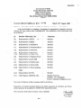
Annexure- 1 : CEA letter dated 24th August, 2009 constituting the
Committee
v
205: 207
Standard Technical Features of BTG System for Supercritical 660/800 MW Thermal Units
SECTION -1
GENERAL
Standard Technical Features of BTG System for Supercritical 660/800 MW Thermal Units
CHAPTER 1
INTRODUCTION
1.1
Supercritical Technology
The current thrust of thermal power development in the country is on
supercritical units so as to improve the conversion efficiency and reduce
carbon footprint. A number of power generation utilities are going for
supercritical technology and a large number of supercritical units of 660/800
MW size are already under construction. Apart from BHEL and L&T, several
other manufacturers are setting up facilities for manufacturing supercritical
boilers and turbine generators in the country. Considering these developments,
this document on “Standard technical features for BTG system of supercritical
660/800 MW thermal units” has been prepared with a view to evolve common
understanding amongst utilities, manufacturers and consultants on design and
sizing philosophy for supercritical units. The objective is to incorporate broad
functional aspects deemed necessary for specifying major quality and
performance parameters unambiguously; and at the same time provide
flexibility to the manufacturers. Steam generator and auxiliaries, being the
major focus area for supercritical units, have been dealt with in more detail.
This document is not intended to be detailed specification for use as bid
document.
The generation efficiency of coal fired stations depends on the steam
parameters adopted - higher the steam parameters, higher is the efficiency. It is
with this objective that the steam parameters have been constantly raised from
60 kg/cm 2 for 50 MW units to 170 kg/cm2 for 500 MW units. Supercritical
technology implies use of steam pressure beyond the critical point of
water/steam which is about 225 kg/cm2. Thus, supercritical units use higher
steam parameters of over 240 kg/cm2
with various combinations of
temperature and pressure. This has been made possible largely through
developments in materials technology to withstand the higher temperatures
and pressures in the boiler.
World over the supercritical technology has been driven by the need to
achieve higher efficiency in order to reduce specific fuel consumption and
green house gas emissions. Supercritical technology is an established and
proven technology with over 500 supercritical units operating worldwide and
reliability and availability of supercritical units being at par with that of subcritical units. Ultra supercritical parameters with pressure of 250-300 kg/cm2
and main steam/ reheat steam temperatures of 600/6100C are also being
adopted. Research is underway to further increase the steam temperatures to
7000C.
Whilst the earlier supercritical units installed in the country adopted steam
parameters of 247 kg/cm2, 535/5650C, higher steam parameters of 247 kg/cm2,
565/5930C are being adopted for later units and have been adopted in this
1
Standard Technical Features of BTG System for Supercritical 660/800 MW Thermal Units
document. The Central Electricity Authority (Technical Standards for
Construction of Electrical Plants and Electric Lines) Regulations, 2010,
stipulate the maximum turbine cycle heat rate for supercritical units as 1850
kcal/kWh with turbine driven BFP and 1810 kcal/kWh with motor driven BFP
and this would require adoption of minimum steam parameters of 247 kg/cm2,
565/ 5930C at turbine inlet. Efficiency improvement of about 2.38 % over the
present 500 MW sub-critical units is expected with these minimum steam
parameters. Parameters higher than above may also be adopted to achieve
better heat rate/ efficiency as per standard practice of OEM.
Supercritical technology being a recent introduction in the country, a brief
introduction of this technology along with implications on design/construction
has also been covered hereunder.
1.2
Implications on Design/Construction
Adoption of supercritical technology involves several design/construction
changes intrinsically associated with this technology. Some other issues also
emanate due to larger unit size of supercritical units. These are discussed as
under:
1.2.1
Evaporator design
Unlike at sub-critical pressures, there is no co-existence of the two phases,
water and steam at supercritical pressures and there is no fixed transition point
for phase change like the drum in sub-critical boiler acting as evaporation end
point. Therefore the standard circulation system (natural/assisted), which
relies on the density difference between steam and water and steam separation
in drum is no longer suitable for supercritical units. Instead, supercritical units
necessarily use a once-through type of boiler. These boilers also operate in
subcritical recirculation mode, subcritical once- through mode and
supercritical mode under different pressure regimes.
Many types of supercritical once through boiler design exist. While some
allow complete variable pressure operation, where the pressure across whole
boiler is varied (reduced at low loads), others operate at fixed evaporator
pressure and thus involve loss of energy for part load operation. Due to
requirement of cyclic operation, variable pressure type evaporator system has
been adopted in this document.
1.2.2
Water walls design
Supercritical units deploy spiral wall furnace using smooth tubes or vertical
wall furnace with rifled tubes. Spiral wall furnace increases the mass flow per
tube by reducing the number of tubes needed to envelop the furnace without
increasing the spacing between the tubes. It also leads to uniform heat
absorption in each tube rendering the spiral wall system less sensitive to
changes in the heat absorption profile in the furnace. However, it involves a
complex support structure and is relatively difficult to construct and maintain.
2
Standard Technical Features of BTG System for Supercritical 660/800 MW Thermal Units
The vertical water wall design uses rifled tubing for improved cooling effect
with uniform temperature across the walls and is also operating satisfactorily.
Its advantage lies in ease of construction and maintenance. Keeping in view
the fact that various manufacturers have standard water wall configurations
which are proven, both the options viz. spiral and vertical tube designs have
been included.
1.2.3
Boiler start up circulation systems
Supercritical boiler starts operating in the once through mode beyond a
particular minimum load of say 30 to 40 %. Below this load, it operates in the
circulation mode and needs a separator and circulation system for water steam
separation; the separated water is circulated back to the boiler. Generally, two
types of circulation systems are in use. In one of the systems, separated water
from the separator is led to the deaerator/ condenser and is circulated to the
feed water system through boiler feed pump. This system is simple and
relatively inexpensive but involves loss of heat from boiler during cold startup. In other system a circulation pump is provided to circulate the water from
separator directly to the economizer. This prevents heat loss from boiler
during cold start- up but adds to cost. Both systems have also been provided in
some of the supercritical units to improve reliability. Other proven standard
systems for boiler startup drain circulation system are also acceptable.
An alternate drain connection to main condenser has also been envisaged to
enable start up of steam generator even when the Start up drain recirculation
pump is not in service and for initial flushing of boiler to achieve water/ steam
quality.
1.2.4
HP turbine extraction
In the sub-critical units upto 500 MW, the highest pressure extraction in the
regenerative feed heating cycle is from the HP Turbine exhaust. This
conventional design with highest feed water extraction from CRH line is able
to achieve a final feed water temperature of about 2550C. Designs with
extraction from HP turbine are available leading to increased final feed water
temperature of about 2900C or higher. The higher feed water temperature due
to HP extraction leads to a marginally better turbine cycle heat rate. It also
involves additional heaters. Keeping in view the advantages of higher
efficiency, design with HP turbine extraction has been adopted.
1.2.5
Boiler feed pump configuration
A number of configurations viz. 2x50% TDBFP+2x30% MDBFP, 2x50%
TDBFP+1x50% MDBFP, 2x50% TDBFP+1x30% MDBFP, 3x50% MDBFP
are in use for boiler feed pumps in large size units. The normal practice being
followed in the country for 500 MW units is to provide 2x50 % turbine driven
Boiler feed pumps (TD-BFP) and 1x50 % motor driven BFP (MD-BFP). The
above configuration has the advantage for having same pump for both TDBFP and MD-BFP leading to interchangeability of spares etc. and better
3
Standard Technical Features of BTG System for Supercritical 660/800 MW Thermal Units
inventory management. For large size supercritical units also, the same
configuration i.e. 2x50 % TD-BFP and 1x50 % MD-BFP has been adopted.
Alternate provision of 3x50% MDBFPs has also been suggested. However,
this shall be resulting in increased auxiliary power consumption and reduced
net unit output.
1.2.6
Design pressure of HP heaters and feed water piping
In case of sub-critical units, feed regulating station is generally located at
down stream of HP heaters, and HP heaters and feed water piping from BFP
discharge to boiler inlet are normally designed for the shut off head condition
of BFPs. However, in case of supercritical units, such a design criteria may
lead to extremely high design pressure rating for HP heaters and lead to
extremely high thicknesses for pipes and heater tube sheet etc. Thus, in
supercritical units, feed regulating station is located at upstream of HP heaters
and no isolation valve is provided at economiser inlet. The feed water piping
and HP heaters are designed as per design pressure of the boiler with provision
of pressure relief valves across HP heaters or media operated three way valves
are provided at inlet/ outlet of HP heater(s) so as to prevent BFP shut off
pressure from being communicated to downstream piping system and HP
heaters.
1.2.7
Water chemistry
Unlike the sub-critical units that offer flexibility for water chemistry
correction in the boiler (drum), the supercritical units require necessary quality
correction of condensate to ensure final steam quality. High chemical
concentration in the boiler water and feed water cause furnace tube deposition
and allow solids carryover into the superheater and turbine. Further, dissolved
oxygen attacks steel and rate of attack increases sharply with rise in
temperature. Accordingly, water chemistry of boiler feed water is maintained
using combined water treatment (oxygen dosing and ammonia dosing in
condensate and feed water system). Oxygenated treatment (OT) using high
purity DM water minimizes corrosion and flow accelerated corrosion (FAC) in
the feed water train. Provision for dosing of ammonia and hydrazine (all
volatile treatment) is also made during start up and chemical excursions.
Further, the units are also provided with 100 % condensate polishing units to
achieve requisite condensate quality to the regenerative feed heating systems.
1.2.8
ID fan selection
Normal practice in the country has been to provide radial type Induced
Draught (ID) fans for upto 500 MW unit size as radial fans are considered
more reliable specially under conditions of high dust loadings (and consequent
high wear of fan). However, radial fans of high capacity (for 660/800 MW
unit size) may not be available and hence axial type variable pitch ID fans
have been adopted. These are more efficient and lead to considerable power
savings. Also with considerable improvements in ESP performance, problems
of fan wear etc. are not expected to be significant.
4
Standard Technical Features of BTG System for Supercritical 660/800 MW Thermal Units
1.2.9
Materials
High steam pressure and temperature parameters adopted in supercritical
boilers require use of improved materials to withstand the severe operating
conditions. Gas side corrosion & erosion and steam side scaling and
exfoliation are some of the major issues in material selection for coal-fired
boilers. Higher temperature leads to creep, high temperature oxidation and
accelerated attack of materials due to the presence of aggressive corrosive
species, such as sulphur and chlorine, in the coal.
Ferritic, austenitic, or nickel-based alloy with mechanical strength at high
temperatures are used in supercritical boilers. Materials being used are T11,
T12, T22, T23, T/P91, T/P92, TP-304H, TP-347H and super-304H or
equivalent. The relative use of these materials for various surfaces depends on
the steam parameters adopted and also on design philosophy of the
manufacturer. The high temperature superheater sections normally require
advanced materials; however use of advanced materials in other sections can
provide design flexibility (e.g., thinner piping/headers for cycling service),
though they may not be essential in those areas. Thus sufficient flexibility has
been provided for choice of materials for various equipments/ sections and
piping to enable design freedom to the manufacturers.
5
Standard Technical Features of BTG System for Supercritical 660/800 MW Thermal Units
CHAPTER - 2
OPERATING CAPABILITY OF PLANT
2.1
The plant shall be designed to operate as a base load station and shall have a
design life of minimum twenty five (25) years. However, continuous operation
under two shift and cyclic modes during certain periods is also envisaged. The
design of the plant equipment and control system would permit participation
of the plant in automatic load frequency control. The major operating
capabilities for the unit(s)/ plant are envisaged as under:
2.1.1
Operate continuously with turbine under VWO condition with rated steam
parameters, specified rated condenser pressure and 1% cycle make up.
2.1.2
Sliding pressure/ modified sliding pressure operation from rated load down to
40% of rated load. The modified sliding pressure operation shall comprise of
constant pressure operation from rated load to approximately 90% of rated
load and then sliding pressure operation down to 40% of rated load. At any
operating load upto 100% rated load, the turbine shall be capable to achieve an
instantaneous increase in turbine output by 5% of the corresponding load, by
opening turbine control valves/ overload valves wide open.
2.1.3
The plant shall have adequate provision for quick start-up and loading of the
units to full load at a fast rate.
2.1.4
Operate continuously with all HP heaters out of service with maximum
specified cooling water temperature, 1% cycle make up and normal auxiliary
steam requirement being tapped from cold reheat line, to generate maximum
output without over stressing turbine components. The power output of the
unit under this operating condition shall not be less than the rated output (660
or 800 MW, as applicable).
2.1.5
In case of sudden reduction in demand (load throw off), the unit should get
safely unloaded and stabilized for operation at house load with HP- LP bypass
open to required capacity.
2.1.6 Operate continuously at rated output (660 or 800 MW, as applicable) under
rated steam conditions, specified worst condenser pressure, 1% cycle make-up
and 47.5 Hz grid frequency.
2.1.7
The design of the plant equipment and control system would permit
participation of the plant in automatic load frequency control.
2.2
Steam generator, turbine generator and auxiliaries shall be designed to cater to
the above operating conditions with adequate margin as per standard practice
prevailing in the fossil fired power plants.
6
Standard Technical Features of BTG System for Supercritical 660/800 MW Thermal Units
CHAPTER - 3
GENERAL TECHNICAL REQUIREMENTS
3.1
All equipment, systems and work covered herein shall comply with all latest
statutes, regulations and safety codes, as applicable in the locality where the
equipment will be installed.
3.2
The design of Steam Generator shall meet or exceed all the requirements of
latest editions of Indian Boiler Regulations (IBR). Any other standard
acceptable to IBR can also be considered, provided that the requirements of
that standard are equivalent or more stringent than the IBR requirements.
3.3
The turbine generator shall comply with general requirements and standards of
latest versions of IEC-45 and 46, IEEE-122, IEC-34-1, IEC-34-3 or their
approved equivalents.
3.4
The design, construction and testing of all equipment, facilities, components
and systems shall be in accordance with latest version of relevant standards
and codes issued by Bureau of Indian Standards (BIS) and/or reputed
international standards and codes. However, in the event of any conflict
between the requirements of the international standards or codes and the
requirements of the BIS standards or codes, the more stringent of the two shall
be adopted. Complete design including pressure parts, piping, valves and
fittings shall meet or exceed all the requirements of the latest versions of
Indian Boiler Regulations (IBR).
3.5
The various parts or components or assemblies of equipment and systems shall
be of proven materials with well established physical and chemical properties
appropriate to the service as intended.
3.6
All materials, components and equipment shall be tested at all stages of
procurement, manufacturing, erection, commissioning as per comprehensive
Quality Assurance Programme to be agreed mutually between the purchase
and the equipment supplier.
3.7
Noise level for the continuously operating equipment shall not be more than
85 dBA at a distance of 1 metre and at a height of 1.5 metre from any
equipment except in case of Turbine – Generator. Noise level for TurbineGenerators shall not exceed 90 dBA. For short term exposure, noise levels
shall not exceed the limits as stipulated in the Occupational Safety & Health
Administration (OSHA) Standard.
3.8
Areas where a potential flammable atmosphere may exist shall be classified in
accordance with the provisions of latest version of relevant IS. Certified
equipment shall be used in the designated hazardous areas. To the extent
practicable, equipment requiring operator’s attention and/or electrical
equipment shall not be installed in hazardous areas.
7
Standard Technical Features of BTG System for Supercritical 660/800 MW Thermal Units
3.9
All power cycle pumps shall comply with the latest applicable
recommendations of Hydraulic Institute Standards (U.S.A.) or approved
equivalents.
3.10
Stand-by equipment of all the auxiliaries which have direct impact on
operation and safety of the plant shall be designed for auto start up, on failure
of running equipment with minimum time delay and without runback on unit
load.
3.11
The equipments and auxiliaries shall be suitable for continuous operation in
the frequency range of 47.5 Hz to 51.5 Hz.
3.12
Wherever oil coolers for any equipment are provided, these shall be of 3x50%
or 2x100% capacity to facilitate cleaning without shutting down the
equipment. All coolers/jackets shall be designed to take care of the operating
pressure of the cooling medium.
3.13
The turbine generator shall be provided with electronically controlled
governing system with appropriate speed/ load characteristics to regulate the
frequency. The governor shall have a droop of 3 to 6%.
8
Standard Technical Features of BTG System for Supercritical 660/800 MW Thermal Units
CHAPTER - 4
LAYOUT CONSIDERATIONS
4.1
The broad salient features of the layout arrangements of various equipment in
the main plant building housing the turbine- generator and its auxiliaries and
steam generator area are given as hereunder:
4.1.1
The arrangement of the turbine- generator in the main plant building shall be
of longitudinal type. The boiler centre line shall be the same as that of TG
condenser as far as possible. Unit pitching distance between centre lines of
two boilers shall be in the range 110- 135m for 660 MW units and 125- 150 m
for 800 MW units. The column spacing of main plant building may be about
10 m.
4.1.2
The conventional arrangement of AB, BC and CD longitudinal bays with D
row as first row of boiler columns shall preferably be adopted. The width of
AB bay shall be about 36m when TDBFPs are located at operating floor in AB
bay and about 30m when TDBFPs are not located as above. The coal mils
shall be located on two sides of the boiler and width of the mill bunker
building on each side shall be such that adequate space is available for
operation and maintenance of coal mills. Alternatively, front/ rear mill
arrangement shall also be acceptable subject to feasibility of the layout. In
case of front mill arrangement, suitable provisions shall be made to prevent
coal dust entry in the TG area.
4.1.3
A clear walkway of 1200mm (min) shall be ensured between the mills / its
foundation / mill reject vessel edge and inner face of mill bay column. Raw
coal bunker shall be circular in shape.
4.1.4
Two transverse bays at 0.0 m elevation equivalent to minimum area of 600m2
shall be provided for unloading and maintenance at one end of main plant
building. One additional bay shall be provided between two units for
maintenance at ground floor. Alternatively, two transverse bays may be
provided between two units for unloading and maintenance with one bay on
one end of the building for maintenance at ground floor. Further, a minimum
lay down area of 600 m2 per unit with EOT crane approach shall be kept on
the operating floor.
4.1.5
TDBFPs shall be located at operating floor/ ground floor in AB/BC bay and
MDBFP shall be located at ground floor or mezzanine floor.
4.1.6
The location of control room (common for two units) shall be towards BC bay
in between the two units at the operating floor level. The control equipment
room shall be located adjacent to control room and at mezzanine floor as per
the requirement.
9
Standard Technical Features of BTG System for Supercritical 660/800 MW Thermal Units
4.1.7
There shall be no regular basement floors in main plant building and mill
bunker bay building. Also, the local pits/trenches in main plant building/ mill
bunker bay building/ boiler/ ESP area shall be avoided as far as possible.
4.1.8
The dearator shall be located in the BC bay at an appropriate elevation so as to
meet the NPSH requirement of boiler feed pumps. Horizontal HP heaters and
LP heaters shall also be located in BC bay with space provision for tube/ shell
withdrawal.
4.1.9
Clear walk ways of minimum 1.5 m width at all the levels along A & B row
shall be provided in the main plant building. For interconnection with service
building, walk way of about 3.0 m width shall be provided along 'B' row of
main plant building.
4.1.10 For EOT crane maintenance, through walkway of minimum 500mm width
(without hindrance) shall be provided along A row and B row rails at crane
girder level. Approach to the crane through cage/ rung ladders shall be
provided at least at two places from the operating floor level.
4.1.11 Interconnecting walkways (minimum 1.5m clear width) between main plant
building and boiler (on either side of boiler in case of side mill arrangement) at
ground, mezzanine, operating and deaerator floor levels shall be provided.
Also, inter-connecting platform (minimum 1.2 m clear width) between boiler
and coal bunker building at mill maintenance floor level, feeder floor level,
tripper floor level and roof of mill bay (if applicable) shall be provided.
Number of interconnecting platforms between boiler and coal bunker building
for each level/ floor specified above shall be two (2) numbers on each side of
Boiler i.e. four (4) numbers per floor in case of side mill arrangement and two
(2) numbers per floor for front/ rear mill arrangement.
4.1.12 Steam turbine, generator (except stator), BFPs and other equipments located in
the turbine hall shall be accessible by the EOT crane(s) for their handling
during maintenance and overhauling. For all other equipment/ components
located in the main plant building, suitable handling arrangement viz. cranes/
chain pulley blocks/ monorail hoists etc. as required shall be provided for the
maintenance and overhauling.
4.1.13 Facility shall be provided for handling of condenser water box to enable
maintenance and withdrawal of condenser tubes. Alternatively, condenser
water box with hinge arrangement may be provided. Rolling shutter(s) or
removable sheeting between ‘A’ row columns alongwith extended platform as
necessary shall be provided to facilitate condenser tube withdrawal or
removable of condenser mounted LP heater(s), if applicable.
4.1.14 Facility of crane/ chain pulley block/ monorail hoist etc. shall be provided
alongwith provision of space for maintenance/ overhauling/ handling/ removal
of equipment such as mills, pumps, fans, motors, heaters, heat exchangers,
and handling of APH baskets and coils of economizer and SCAPH etc.
10
Standard Technical Features of BTG System for Supercritical 660/800 MW Thermal Units
4.1.15 Layout of facilities and equipment shall allow removal of generator
transformers, station transformers and unit auxiliary transformers without
disturbing structure, equipment, piping, cabling, bus ducts etc. routed in the
area.
4.1.16 Clear approach width of minimum 10m with clear height of 8m shall be
provided at the front and rear of ESP.
4.1.17 Trestles to be provided for routing of cables, pipes etc. shall have a clear
height of 8.0m in main plant area, at road/ rail crossings so as to clear the road
spaces/ railway lines, approach to maintenance bays of various buildings. A
walkway with hand rails and toe guards of 600mm (minimum) width shall be
provided all along length of the trestle for maintenance of cables and pipes.
Ladders for approach to these walkways shall be provided near roads, passage
ways at suitable locations.
4.1.18 Floor drains shall be provided at all floors and drain discharge pipes shall be
properly sized taking into account the fire water sprinkler system wherever
provided.
4.1.19 Valves shall be located in accessible positions. All piping shall be routed at a
clear height of minimum 2.2 m from the nearest access level for clear man
movement. Best engineering practices shall be adopted for keeping the
minimum clear working space around equipment and clear headroom within
main structures and cable trays etc.
4.1.20 Fire water pipes in main plant area may be routed in trenches filled with sand
and covered with pre-cast RCC covers.
4.1.21 The safety requirements as per the Factories Act, Rules/ Regulations made
under Indian Electricity Act 2003 and other applicable codes/standards etc.
shall be observed while developing the layout.
4.1.22 While developing the layout, all fresh air ventilation louvers shall be
considered 1000 mm from floor level and directed downwards at an angle.
Ventilation fans on AB bay roof shall be staggered and shall not be near the
centre line of turbine- generator set. Air washer units could be located at
outside TG bay on' A' row side and in BC bay on 'B' row side.
4.1.23 As per requirement of MOE&F, the space provision shall be kept for
installation of flue gas desulphurisation (FGD) system in future, if required.
4.1.24 Layout of the buildings shall be developed considering TAC requirements for
fire escape. Adequate fire escape staircases shall be provided in main plant
building with fire doors at each landing. Each equipment room shall be
provided with alternate exits in case of fire/ accidents as per requirements of
Factory Act and statuary bodies / Insurance companies.
4.1.25 Each unit shall be provided with one passenger elevator in TG hall and one
passenger cum goods elevator in the boiler area.
11
Standard Technical Features of BTG System for Supercritical 660/800 MW Thermal Units
CHAPTER 5
PERFORMANCE GUARANTEES
5.1
General Requirements
5.1.1 The equipment shall meet the ratings and performance requirements stipulated
for various equipment. The guaranteed performance parameters shall be
without any tolerance values and all margins required for instrument
inaccuracies and other uncertainties shall be deemed to have been included in
the guaranteed figures.
5.1.2 All the guarantees shall be demonstrated during functional guarantee/
acceptance test. The various tests which are to be carried out during
performance guarantee/acceptance test are listed in this chapter. The guarantee
tests shall be conducted at site on each unit individually.
5.1.3
All instruments required for performance testing shall be of the type and
accuracy required by the code(s) and prior to the test these shall be calibrated
in an independent test Institute. The protecting tubes, pressure connections and
other test connections required for conducting guarantee test shall conform to
the relevant codes.
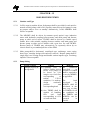
5.1.4
Detailed Performance Test Procedure to be furnished shall contain the
following:
i)
Object of the test.
ii)
Various guaranteed parameters & tests as per contract.
iii)
Method of conductance of test and test code.
iv)
Duration of test, frequency of readings & number of test runs.
v)
Method of performance calculation.
vi)
Correction curves.
vii) Instrument list consisting of range, accuracy, least count, and location of
instruments.
viii) Scheme showing measurement points.
5.1.5
ix)
Sample calculation.
x)
Acceptance criteria.
xi)
Any other information required for conducting the test.
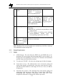
In case during performance guarantee test(s) it is found that the
equipment/system has failed to meet the guarantees, all necessary
modifications and/or replacements shall be carried out to make the
equipment/system comply with the guaranteed requirements & the same shall
be demonstrated by conducting another performance guarantee test at no extra
cost to the purchaser. However, if the contractor is not able to demonstrate the
12
Standard Technical Features of BTG System for Supercritical 660/800 MW Thermal Units
guarantees, even after the above modifications/ replacements within ninety
(90) days or a reasonable period allowed by the purchaser, after the tests have
been completed, the purchaser will have the right to either of the following:
i)
For Category-I Guarantees
Reject the equipment/ system/ plant and recover the payment already
made
OR
Accept the equipment/ system/ plant after levying Liquidated Damages
as stipulated. (Amount of LD to be specified by the purchaser based on
unit size, coal cost etc.)
ii)
For Category-II Guarantees
Reject the equipment/ system/ plant and recover the payment already
made. Conformance to the performance requirements under Category-II
is mandatory.
iii)
For Category-III Guarantees
Reject the equipment/ system/ plant and recover the payment already
made.
OR
Accept the equipment/ system after assessing the deficiency in respect of
the various ratings, performance parameters and capabilities and recover
amount equivalent to the damages.
5.2
Guarantees Under Category-I
The performance guarantees which attract liquidated damages are as follows:
5.2.1
Efficiency of the steam generator at 100% TMCR with zero make up while
firing the design coal at rated steam parameters, rated coal fineness and rated
excess air.
5.2.2 Efficiency of the steam generator at 80% TMCR with zero make up while
firing the design coal at rated steam parameters, rated coal fineness and rated
excess air (for reference).
5.2.3 Steam generating capacity in T/hr. of steam at rated steam parameters at
superheater outlet and rated steam temperature at reheater outlet (with any
combination of mills working as per purchaser’s discretion) with the coal
being fired from within the range specified.
5.2.4
Turbine Cycle Heat Rate in kcal/kWh under rated steam conditions, design
condenser pressure with zero make up at 100% TMCR load.
13
Standard Technical Features of BTG System for Supercritical 660/800 MW Thermal Units
5.2.5
Turbine Cycle Heat rate in kcal/kWh under rated steam conditions, design
condenser pressure with zero make up at 80% TMCR load (for reference).
5.2.6
Continuous TG output at 105% TMCR load under rated steam conditions,
design condenser pressure with zero make-up.
Note: The condenser pressure measurement while conducting the guarantee
tests from clause 5.2.4 to 5.2.6 above shall be measured at 300 mm above the
top row of condenser tubes.
5.2.7
1
5.2.8
The total auxiliary power consumption for all the auxiliaries of boiler, turbine
Generator and turbine cycle equipments required for continuous unit operation
at 100% TMCR load under rated steam conditions and at design condenser
pressure with zero make-up.
5.2.9
The total auxiliary power consumption for all the auxiliaries of boiler, turbine
Generator and turbine cycle equipments required for continuous unit operation
at 80% TMCR load under rated steam conditions and at design condenser
pressure with zero make-up (for reference).
5.3
Guarantees Under Category-II
5.3.1
It shall be guaranteed that, with one field out of service in each stream, the
particulate emission from ESP at TMCR load and design coal firing shall not
exceed 50 mg/Nm3 or stipulated requirement of MOEF’s in this regard,
whichever is more stringent. The corresponding ESP efficiency shall be
worked out.
5.3.2
It shall be guaranteed that maximum total NOx emission from the unit will not
be more than 260 grams of NOx (from thermal as well as fuel) per giga joule
of heat input to the boiler at 6% O2 level during the entire operating range of
steam generator for the range of coals specified or as per MOEF’s requirement
in this regard (if applicable) whichever is more stringent.
5.4
Guarantees Under Category-III
Pressure drop across terminal points of condenser cooling system with on-line
condenser tube cleaning system in operation.
The parameters/ capabilities to be demonstrated for various systems/
equipments shall include but not be limited to the following:
5.4.1
Run back capabilities
The automatic runback capability of the unit (boiler- turbine-generator) on loss
of critical auxiliary equipment (such as tripping of one ID /FD /PA fan/ BFP
etc.) shall be demonstrated ensuring smooth and stable runback operation.
1
Applicable in case CW pumps are not included in scope of BTG system.
14
Standard Technical Features of BTG System for Supercritical 660/800 MW Thermal Units
5.4.2 Start up time (for one unit only)
Start-up time (upto full load), and loading capabilities for the complete unit
(boiler, turbine and generator together) for cold start, warm start and hot start
conditions as agreed shall be demonstrated, ensuring that the various turbine
operational parameters like vibration, absolute and differential expansion,
eccentricity and steam metal temperature mismatch etc. are within design
limits.
5.4.3
Rate of change of load and sudden load change withstand capability
The capability of boiler-turbine-generator in regard to ramp rate and step load
change as specified shall be demonstrated.
5.4.4
Mill capacity at rated fineness
Performance testing shall be done on coal mills towards establishing the
specified capacity at the rated fineness, applying corrections for the variation
in coal characteristics i.e., HGI (Hardgrove Grindability Index) and total
moisture. The test shall be demonstrated on 50% of the installed coal
pulverizers (of Purchaser's choice) of each Steam Generator at 100% mill
loading with the originally installed grinding elements in nearly worn-out
condition or at the end of guaranteed wear life of grinding elements,
whichever is earlier. Capacity test shall be demonstrated at the following
conditions occurring simultaneously during testing:
i) Coal fineness Not less than 70% through 200 mesh and not less than
98% through 50 mesh screen.
ii) Test coal
Any available coal from the specified range with coal
sampling done as per ISO 9931.
In case the guaranteed capacity of coal pulverizers as stated above are
successfully demonstrated, remaining coal pulverizers of corresponding steam
generator will also be considered to have successfully met the above capacity
guarantee requirement. However, in the event of any of the coal pulverizers
not meeting the guarantee test, all the coal pulverizers of corresponding steam
generator will have to be tested to demonstrate guaranteed capacity.
5.4.5
Life of mill wear parts
Life of mill wear parts, in hours of operation, for the entire range of coal
characteristics specified shall be demonstrated.
15
Standard Technical Features of BTG System for Supercritical 660/800 MW Thermal Units
5.4.6
5.4.7
Electrostatic precipitator
i)
The ESP air in leakage shall not be more than 1% of total gas flow at
ESP inlet at the guarantee point condition and shall be demonstrated.
ii)
The maximum pressure drop through the ESP at the guarantee point flow
condition shall not exceed 25 mmwc and shall be demonstrated.
iii)
Uniformity of the gas distribution in the various streams and inside the
casing shall be demonstrated as per specified/ quoted value.
No fuel oil support above 40% BMCR load
It shall be demonstrated that oil support for flame stabilization shall not be
required beyond 40% of BMCR load when firing the coals from the range
identified. It shall also be demonstrated that with any combination of mills/
adjacent mills in service, the steam generator shall not require any oil firing
for stable and efficient boiler operation at and above 40% BMCR load.
5.4.8
Performance characteristics of fans
Satisfactory operation of FD, ID and PA fans without undue noise and
vibration while operating in isolation or in parallel with other fans shall be
demonstrated at site.
5.4.9
Steam temperature imbalance
It shall be demonstrated at SH and RH outlets (in case of more than one outlet)
that the temperature imbalance between the outlets does not exceed 100 C
under all load conditions.
5.4.10 SH and RH tube metal temperature
It shall be demonstrated that superheater and reheater tube metal temperature
at critical locations remain within maximum tube metal temperature limits as
per design of the OEM under various load conditions (i.e. 100%, 80%, 60% &
50%).
5.4.11 Superheater and reheater attemperation system
It shall be demonstrate that the spray water flow of SH attemperation system
does not exceed 8% of main steam flow, at superheater outlet, while firing any
coal from within the range specified with HP heaters in service while
maintaining the rated SH outlet steam temperature at all loads upto and
including BMCR. It shall also be demonstrate that the RH temperature is
maintained at the rated value without any spray water requirement under
normal operating conditions.
16
Standard Technical Features of BTG System for Supercritical 660/800 MW Thermal Units
5.4.12 Furnace exit gas temperature (FEGT)
It shall be demonstrated that maximum furnace exit gas temperature (FEGT)
shall be minimum 60 deg C below the minimum initial deformation
temperature (IDT) of ash. A comprehensive thermal performance test (TPT)
shall be conducted for this purpose on one unit. FEGT shall be demonstrated
through such TPT by indirect measurement.
5.4.13 Air heater air in leakage
It shall be demonstrated that the air-heater air-in-leakage after 3000 hours of
steam generator operation does not exceed the specified/ quoted values.
5.4.14 Equipment cooling water system
i)
Inlet and outlet temperatures on the primary and secondary side of the
plate type heat exchangers as per design shall be demonstrated at site.
ii)
Pressure drop across plate type heat exchanger on primary and secondary
side cooling water circuits shall be demonstrated at site.
iii)
Satisfactory operation of primary side DMCCW pumps and secondary
side cooling water pumps (as applicable) without undue noise and
vibration while operating in isolation or in parallel with other pumps
shall be demonstrated at site.
5.4.15 Generator excitation system
The performance of generator excitation system as specified shall be
demonstrated.
5.4.16 Steam condensing plant
i)
The value of design condenser pressure, to be measured at 300 mm
above the top row of condenser tubes, shall be demonstrated under VWO
condition, 1% make-up, design CW inlet temp. and CW flow. The
condenser vacuum shall be measured with a vacuum grid utilizing
ASME basket tips.
ii)
Temperature of condensate, at outlet of condenser, shall be demonstrated
to be near to saturation temperature corresponding to the condenser
pressure at all loads.
iii)
Oxygen content in condensate at hotwell outlet shall not exceed 0.015
cc/litre over 50-100% load range and shall be determined according to
calorimetric Indigo-Carmine method.
iv)
Air leakage in the condenser under full load condition shall not exceed
more than 50% of design value taken for sizing the condenser air
evacuation system.
17
Standard Technical Features of BTG System for Supercritical 660/800 MW Thermal Units
v)
When one half of the condenser is isolated, condenser shall be capable of
taking at least 60% T.G. load under TMCR conditions.
vi)
The design capacity of each vacuum pump in free dry air under standard
conditions at a condenser pressure of 25.4 mm Hg (abs) and sub cooled
to 4.170C below the temperature corresponding to absolute suction
pressure shall be demonstrated. Correction curves for establishing the
capacity at site conditions shall also be furnished.
vii) The air and vapour mixture from air cooling zone of condenser shall be
0
4.17 C below the saturation temperature corresponding to 25.4 mm Hg
(abs) suction pressure. Correction curves for establishing the same at site
conditions shall also be furnished.
viii) 2Pressure drop across terminal points of condenser cooling system with
on line condenser tube cleaning system in operation.
5.4.17 Feed water heaters and deaerator
The following parameters shall be demonstrated:
i)
TTDs and DCAs of feed water heaters shall be demonstrated as per
guaranteed heat balance diagram for 100% TMCR condition.
ii)
Outlet temperature from final feed water heater(s).
iii)
Difference between saturation temperature of steam entering the
deaerator and temperature of feed water leaving the deaerator shall be
demonstrated as per guaranteed heat balance diagram for 100% TMCR
condition.
iv)
Continuous and efficient operation and performance of feed heating
plant without undue noise and vibrations at all loads and duty conditions.
5.4.18 HP & LP bypass system capabilities
The design capacity of HP/ LP bypass system shall be demonstrated. Further,
the HP & LP bypass system should satisfy the following functional
requirements under automatic interlock action. It should come into operation
automatically under the following conditions:
2
i)
Generator circuit breaker opening.
ii)
HP & IP stop valves closing due to turbine tripping.
iii)
Sudden reduction in demand of external load (load throw off).
Applicable in case CW pumps are included in scope of BTG system.
18
Standard Technical Features of BTG System for Supercritical 660/800 MW Thermal Units
Under all above conditions, while passing the required steam flows as per the
relevant heat balances, the condenser should be able to swallow the entire
steam without increasing the exhaust hood temperature and condenser
pressure beyond the maximum permissible values. The same shall be
demonstrated.
5.4.19 Power cycle pumps
Satisfactory operation of BFPs and CEPs without undue noise and vibration
while operating in isolation or in parallel with other pumps shall be
demonstrated at site.
5.4.20 Condenser on load tube cleaning system
Life of sponge rubber balls and number of balls lost during 1000 hours of
plant operation as agreed in contract shall be demonstrated.
5.4.21 Automatic on-line turbine testing (ATT) system
On-load testing of turbine protective equipments without disturbing normal
operation and keeping all protective functions operative during the test shall
be demonstrated.
5.4.22 Noise
i)
All the plant, equipment and systems shall perform continuously without
exceeding the specified noise level over the entire range of output and
operating frequency.
ii)
Noise level measurement shall be carried out using applicable and
internationally acceptable standards. The measurement shall be carried
out with a calibrated integrating sound level meter meeting the
requirement of IEC 651 or BS 5969 or IS 9779.
iii)
Surface sound pressure shall be measured all around the equipment at a
distance of 1.0 m horizontally from the nearest surface of any
equipment/ machine and at a height of 1.5 m above the floor level in
elevation. The average of A-weighted surface sound pressure level
measurements expressed in decibels to a reference of 0.0002 micro bar
shall not exceed 85 dBA except for:
a) Safety valves and associated vent pipes for which it shall not exceed
115 dBA with silencer as applicable.
b) Regulating drain valves in which case it shall be limited to 90 dBA.
c) TG unit in which case it shall not exceed 90 dBA.
d) HP and LP bypass valves operation for which it shall be restricted to
115 dBA.
19
Standard Technical Features of BTG System for Supercritical 660/800 MW Thermal Units
e)
For air motors it shall not exceed 95 dBA.
f)
For pressure regulation valves & steam generator water drain
control valve it shall not exceed 90 dBA.
Corrections for background noise shall be considered in line with the
applicable standards.
5.4.23 Condensate polishing plant
i)
Effluent quality at outlet of each vessel at its rated design flow and
design service length between two regenerations.
ii)
Pressure drop across the polisher service vessel, as specified, in clean
and dirty condition of resin at rated design flow.
5.4.24 Control & Instrumentation system requirements
Performance guarantee tests for closed loop control systems shall be carried
out at site to verify the integrated performance of the C&I system and to verify
as to whether all the important parameters remain within stipulated
permissible limits under all the operating conditions. In case during these tests
or otherwise it is observed that the behavior/ response of individual system
(drives actuators/ valves etc.) is not satisfactory/ acts as a limitation/ restriction
in achieving the permissible limits, all required modifications, rectification etc.
shall be made in the C&I system so that the permissible limits can be
achieved.
5.4.25 EOT crane
After assembly and erection of crane at site, the crane shall be subjected to
deflection test, overload test, brake test and other tests as per IS 3177.
5.4.26 Elevators
After installation at site, the elevators shall be subjected to the following tests:
5.5
i)
Overload test.
ii)
Travel speed and hoist speed checks.
iii)
Drop test.
iv)
Checks for interlocks & safety systems.
v)
Checks for operation from inside the cage.
Test Codes, Test Conditions etc.
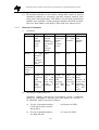
5.5.1 Steam generator efficiency
i)
The steam generator efficiency shall be determined as per the
requirements of ASME PTC- 4 (by energy balance method) and other
stipulations brought out hereunder.
20
Standard Technical Features of BTG System for Supercritical 660/800 MW Thermal Units
a) Test loads
b) Test conditions
c)
d)
e)
f)
g)
ii)
100% TMCR and 80% TMCR.
Boiler operating at rated steam parameter, excess
air, coal fineness and firing design coal.
Ambient
27oC dry bulb temperature and 60% relative
conditions
humidity. The reference air temperature for the
efficiency guarantee/ testing shall be taken as
27oC at APH inlet (without consideration of heat
credits).
No. of readings Two sets of consistent readings for each of test
loads. Average of the test efficiencies based on
above two readings for each load shall be
considered for evaluation.
APH leakages to Guaranteed or actual whichever is higher.
be considered
Test duration
Four hours. No soot blowing shall be allowed
during the test period or during stabilization
period of four hours prior to commencement of
the test.
Heat credits
No heat credits allowed. The guaranteed steam
generator efficiency shall be without any heat
credit.
The guaranteed efficiency shall comply with following limiting
parameters with design coal firing:
a) Excess air at economizer outlet at 20% (minimum).
100% TMCR load
0
b) Corrected flue gas temperature
125 C or as predicted by the
(at 100% TMCR load)
supplier at air preheater outlet
whichever is higher.
c) Boiler efficiency loss to be
Minimum 1%.
considered due to unburnt carbon
iii)
The following correction curves shall be applicable for performance test
of the steam generator:
a) Ambient air temperature.
b) Relative humidity of ambient air.
c) Hydrogen in coal.
d) Moisture in coal.
e) Gross calorific value of coal.
f)
Feed water temperature at economiser inlet.
5.5.2 Performance test of ESP
i)
The performance/ acceptance tests shall be carried out in accordance
with method-17 of EPA (Environmental Protection Agency of USA)
code.
21
Standard Technical Features of BTG System for Supercritical 660/800 MW Thermal Units
ii)
The following correction curves shall be applicable for performance test
of the ESP:
a) Inlet flue gas flow.
b) Inlet flue gas temperature.
c) Inlet dust loading.
d)
Sulphur content of coal.
5.5.3 Auxiliary power consumption
The unit auxiliary power consumption shall be calculated using the following
relationship:
Pa
= Pu + TL
Pa
= Guaranteed Auxiliary Power Consumption.
Pu
= Power consumed by the auxiliaries of the unit under the test.
TL
= Losses of the transformers based on works test reports.
While guaranteeing the auxiliary power consumption, all continuously
operating unit auxiliaries shall be included and number of coal mills to be
considered in operation shall be as per requirement of design coal.
5.5.4 Performance/ acceptance test for turbine generator
i)
Performance test for the turbine generator set will be conducted in
accordance with the latest edition of ASME PTC-6.
ii)
Power consumed by the integral auxiliaries mentioned which is to be
deducted from electrical power generated, shall be measured during the
performance/ Acceptance Test. Wherever the measurement is not
possible, design values of power consumption by an auxiliary shall be
considered.
iii)
Corrections to the test results for steam turbine shall be applied as per
the correction curves provided. When the system is properly isolated for
a performance test, the unaccounted for leakages should not be
more than 0.1% of the design throttle flow at full load. However, during
the test, if it is found that the unaccounted for leakage is more than 0.1%
of design throttle flow at full load, then heat rate will be increased by an
amount equal to half the difference between actual unaccounted for
leakage expressed as percentage of design throttle flow at full load and
0.1% (allowed by the code). In case excessive leakage is visible in the
plant area, the source of leakage shall be identified and attended before
commencement of the test.
iv)
The tests shall be arranged in a manner that the normal unit operation is
not disrupted. Duplicate test runs shall be performed at 100% TMCR
and 80 % TMCR loads. The results of corrected heat rate shall agree
within 0.25% and average of two shall be considered heat rate achieved.
22
Standard Technical Features of BTG System for Supercritical 660/800 MW Thermal Units
If they differ by more than 0.25%, additional test run(s) shall be made at
the same point until corrected heat rates of atleast two test runs agree
within 0.25% and achieved heat rate shall be calculated as average of
test run points satisfying the above criterion.
v)
The performance guarantee test shall be carried out after successful
completion of trial operation. Ageing allowance shall be applicable
during evaluation of PG test results in line with ASME-PTC-6 report
1985 (reaffirmed 1991). Period of ageing shall be considered from the
date of successful completion of trial operation to the date of
conductance of PG test. In calculating the above factor, any period(s)
during which the turbine has not been in operation at a stretch for more
than one week shall not be considered.
vi)
The following correction curves shall be applicable for performance test
of the turbine generator:
a) Main steam temperature.
b) Main steam pressure.
c) Reheat steam temperature.
d) Condenser back pressure.
e) Superheater desuperheating spray.
f)
Generator power factor.
g) Generator hydrogen pressure.
The extent of correction admissible for superheater desuperheating spray
shall be with reference to the design value considered in the guaranteed
heat rate HBD.
5.5.5 Performance test for the condensers
i)
Performance test for design condenser pressure shall be conducted in
accordance with latest edition of ASME PTC- 12.2.
ii)
Condenser pressure shall be measured at 300 mm above top row of
tubes under VWO conditions, 1% make-up and design C.W. flow &
design temperature. The condenser pressure shall be measured with a
vacuum grid utilizing ASME basket tips. The grid shall be fitted at 300
mm above top row of condenser tubes.
iii)
Tube plug margin of 5%, as per design condition, shall be considered for
condenser performance calculation at design condition.
iv)
The tube side fouling resistance for design condition shall be calculated
as per specified cleanliness factor. The tube side fouling resistance for
actual test condition shall be measured as per methodology given in
ASME PTC 12.2. Alternately, the same shall be calculated using
expected actual cleanliness factor appropriately assessed considering the
aspect of actual tube cleaning prior to conducting the test.
23
Standard Technical Features of BTG System for Supercritical 660/800 MW Thermal Units
SECTION-2
STEAM GENERATOR &
AUXILIARIES
Standard Technical Features of BTG System for Supercritical 660/800 MW Thermal Units
CHAPTER 6
STEAM GENERATOR
6.1
Type
6.1.1
The Steam Generator shall be of single pass (Tower type) or two pass type
using either spiral wall (inclined) or vertical plain/ rifled type waterwall
tubing.
6.1.2
The Steam Generator shall be direct pulverized coal fired, top supported,
single reheat, radiant, dry bottom, with balance draft furnace and shall be
suitable for outdoor installation. The evaporator of Steam Generator shall be
suitable for variable pressure operation from sub-critical to supercritical
pressure range.
6.1.3
The plants based on indigenous coal may be required to use some proportion
of imported coal also. As such, steam generator shall be appropriately
designed so that it is suitable for indigenous coal and blended coal with
imported coal upto 30% on weight basis.
6.2
Rating of Steam Generator
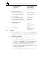
The Steam Generator shall be designed to cater to duty requirements/rating as
specified below:
i)
ii)
Steam flow at superheater
outlet at boiler maximum
continuous
rating
(BMCR)
Steam temperature:
a) At superheater outlet
b) At reheater outlet
iii)
Steam
pressure
superheater outlet
1.02 times the steam flow at turbine
VWO condition plus continuous auxiliary
steam requirement of unit at TMCR,
rounded to next integer divisible by 5.
To correspond to HP turbine inlet
temperature
of
minimum
5650C
[indicative value: minimum 5680C].
To correspond to IP turbine inlet
temperature
of
minimum
5930C
0
[indicative value: minimum 596 C].
at To correspond to turbine throttle steam
pressure of minimum 247 kg/cm2 (abs)
[indicative value: minimum 256 kg/cm2 (abs)].
Feed water temperature at 287.5±2.5oC [or as per optimisation by
economizer inlet
TG supplier].
v)
Steam generator control 50% TMCR to 100% BMCR.
range
Notes:
a) Pressure drop in reheat steam circuit (cold reheat, hot reheat line &
reheater) should not exceed 10% of HP turbine exhaust pressure under
all operating conditions including 100% BMCR condition.
iv)
b) The steam temperatures at superheater and reheater outlet(s) shall be
guaranteed to be maintained at +50C of the rated value under all
operating conditions within the control range.
24
Standard Technical Features of BTG System for Supercritical 660/800 MW Thermal Units
6.3
Fuels
6.3.1
Coal
i)
The primary fuel for the Steam Generator(s) shall be coal (coal
characteristics of design coal, worst coal, best coal and range of coal for
the project to be considered for boiler design).
ii) The Steam Generator shall be designed to give the guaranteed efficiency
when firing the coal having the characteristics for design coal.
iii) The Steam Generator and its auxiliaries shall also be capable of obtaining
the boiler maximum continuous rating (BMCR) when firing the coal
having the characteristics for worst coal. The Steam Generator and its
auxiliaries shall be designed for efficient and trouble free operation when
firing the design, worst and best coals and any of the coals characteristics
in between these for complete load range. The Steam Generator and its
auxiliaries shall also be capable of giving BMCR rating and meet other
operating capabilities, without any trouble and limitations, when firing the
coals having the specified range of characteristics.
iv) Steam Generator and its auxiliaries shall also be capable of obtaining
maximum continuous rating when firing with any of the coal within the
specified range of coal. System redundancies/ margins on equipment/
auxiliary sizing need not be available under such fuel firing condition
unless specifically mentioned otherwise. However, equipments/ systems
shall not exceed their safety limits under such firing, and shall not
transgress into factors of safety as per specification/ codes.
6.3.2
Fuel oil
The fuel oil (HPS/LSHS/HFO) shall be used for start-up, coal flame
stabilization and low load operation of the Steam Generator(s). In addition,
the light diesel oil (LDO) firing facilities shall also be provided for cold start
up of the steam generator(s). Alternatively, only LDO can be used for startup, coal flame stabilization and low load operation including cold start-up.
6.4
Salient Design Features and Capabilities
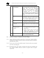
6.4.1
Limiting parameters for steam generator design
The Steam Generator design shall comply with the following limiting
parameters with 'design coal' firing, under stipulated ambient air condition i.e.
270 C temperature and 60 % relative humidity:
i) Excess air at economizer outlet 20% (minimum).
at 100% TMCR load
ii) Corrected flue gas temperature 125oC or as predicted by the supplier at
(at 100% TMCR load)
air preheater outlet (also considering
acid dew point) whichever is higher.
25
Standard Technical Features of BTG System for Supercritical 660/800 MW Thermal Units
6.4.2
Minimum load without oil support for flame stabilization
The design of Steam Generator shall be such that it does not call for any oil
support for flame stabilization beyond 40% BMCR load when firing any coal
from the range specified, with any combination of mills/ adjacent mills in
service.
6.4.3
Loading/unloading pattern and adaptability for sudden load changes/
load throw off
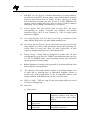
i)
To match the desired plant operating capabilities, the Steam Generator
shall be designed for cyclic/two shift operation. Expected numbers of
Steam Generator startups during design life of minimum 25 years are as
follows:
a) Cold Start (after shut down period exceeding 72
hours)
b) Warm Start (after shut down period between 10 hours
and 72 hours)
c) Hot Start (after shut down period less than 10 hours)
ii)
150
1000
4000
Under the above conditions, no portion of the Steam Generator and the
associated systems shall be stressed beyond acceptable safe stress and
fatigue levels and the design of Steam Generator and its pressure parts
shall take care of above without affecting the life of equipment and
pressure parts adversely.
iii) Steam generator shall also be capable of satisfactory, stable and safe
operation in case of rapid load changes in downward direction due to
external disturbances or equipment malfunction. Under such conditions
the system shall stabilize itself through proven concepts and controls and
within the recommendations of National Fire Protection Association,
USA, NFPA-85.
iv) In case of sudden load throw-off, in worst case from 100% BMCR, the
Steam Generator shall be capable of automatically bringing down the
steam generating capacity to match with HP-LP bypass capacity.
Minimum load of Steam Generator to which it can be brought down under
such condition, during short turbine outages or export load rejection, with
a view to save fuel and reduce heat losses shall be indicated. The boiler
design shall ensure balanced draft condition, avoid overheating of reheater
tubes and such other conditions that jeopardize the safety and life of
boiler.
6.4.4
Operation without high pressure (HP) heaters in service
Steam generator shall be capable of sustained operation with all HP heaters
out of operationwith generation of at least rated power output by the unit.
26
Standard Technical Features of BTG System for Supercritical 660/800 MW Thermal Units
6.4.5
Operation with HP and LP turbine bypass system
i)
With HP-LP bypass system in operation, the unit shall be capable of
smooth start-up, fast loading & house load operation.
ii) Steam Turbine trip will call for boiler operation in HP/LP bypass mode.
Under this condition, the boiler shall be capable of operating with SH
flow corresponding to capacity of HP bypass system and feed water
temperature of approximately 140°C at economiser inlet.
6.4.6
Mode of steam generator operation and rate of loading
i)
As mentioned above, the Steam Generators shall be designed for variable
pressure operation. Thermal design of Steam Generator and the selection
of materials of pressure parts shall be suitable for variable pressure
operational modes.
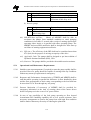
ii) The Steam Generators shall be designed for minimum rate of loading/
unloading mentioned below without compromising on design life of
pressure parts:
a) Step load change : Minimum ±10%
b) Ramp rate
: Minimum ±3% per minute above 30% load
iii) The maximum rates of loading/ unloading achievable with Steam
Generator offered and the corresponding limiting variations (±%) of boiler
parameters such as oxygen in flue gas, SH/RH steam temperature, furnace
draft, etc. shall be indicated.
6.4.7
Steam generator control range
The automatic outlet steam temperature control range of Steam Generator
shall be from 50% TMCR to 100% BMCR for superheater as well as reheater.
Under the above control range, the steam temperatures at SH & RH outlets
shall be maintained at their rated values within allowable +/- 5°C temperature
variation.
6.4.8
Provision for future installation of FGD system
A flue gas desulphurization (FGD) system may be installed in future to meet
the requirements of pollution control. Following provisions need to be kept for
this purpose:
i)
Suitability of duct between ID fan and chimney for future interconnection
of FGD system with minimum modification.
27
Standard Technical Features of BTG System for Supercritical 660/800 MW Thermal Units
ii) The ducting and supporting structure to be designed to take care of future
Guillotine damper to be installed between the two tap offs before
chimney.
6.4.9
Limits of NOx emission
i)
The guaranteed maximum NOx emission (thermal as well as fuel) from
the Steam Generator unit shall not exceed 260 grams of NOx per Giga
Joule (GJ) of heat input to the boiler at 6% O2 level for the range of coals
specified or as per MOEF’s requirement in this regard (if applicable)
whichever is more stringent.
ii) The above value of NOx shall not be exceeded during the entire operating
range of Steam Generator for the whole range of specified coals.
6.4.10 Capital overhaul of steam generator
The design and materials for various equipments/auxiliaries etc. shall be
selected keeping in view capital overhaul of units once in two (2) years, such
that no major repairs/replacements, requiring shutdown of the unit, are needed
in between the capital overhauls.
6.4.11 Noise level
The equivalent weighted average of sound level for continuously operating
equipment measured at a distance of 1.5 m above floor level in each elevation
and one meter horizontally from the base of any equipments furnished,
expressed in decibel to a reference of 0.0002 microbar, shall not exceed 85
dB(A).
6.4.12 Operational requirement
The Steam Generator(s) shall be designed for the following minimum
operational requirements at all loads and for the specified range of coal(s).
i)
ii)
iii)
iv)
v)
vi)
Soot blowing frequency
As
per
OEM’s
recommendation
for
characteristics of the coal
being fired
Preferred mill combination
Any combination of mills
(without any restriction)
Max. coal flow unbalances in coal pipes 5.0%
from same mill, from the average
Slagging :
a) Burner
Nil
b) In furnace/ash hopper/ water wall areas Nil
Maximum permissible reheat spray water 3% of steam flow at
flow with rated steam temperature at reheater outlet
reheater outlet
Maximum gas temperature variation 300C
across furnace width and depth
28
Standard Technical Features of BTG System for Supercritical 660/800 MW Thermal Units
Maximum steam side temperature 100C
imbalance in the LHS & RHS at boiler
outlet (from the average)
viii) Minimum load with separator running dry 30-40 % TMCR (As per
manufacturer’s
proven
practice)
ix) Header pressure unbalance (steam side)
6%
x)
Air ingress from furnace bottom Hopper
As per manufacturer's
predictions
vii)
6.4.13 Safety and relief valves
Boiler Safety valves and relief valves shall have minimum discharge
capacities as under:
i)
ii)
Valve
Spring loaded safety valves at:
a) Separator & superheater
b) Reheater system
Electromatic relief valves at:
a) Superheater outlet
b) Reheater outlet
Minimum discharging capacities
Combined capacity 100% BMCR
Combined capacity 105% of
reheater flow at BMCR
10% BMCR
15% BMCR
6.4.14 Steam purity parameters
Steam purity parameters at outlet of the steam generator shall meet
requirement of turbine manufacturer and shall generally not be inferior to
those indicated below:
6.5
i)
Sodium
: < 3 ppb
ii)
Chloride
: < 3 ppb
iii)
Iron
: < 10 ppb
iv)
Silica
: < 10 ppb
v)
Cation conductivity
: < 0.2 µS/cm
Specifications of Equipment and Systems
The specified requirements shall be complied for the most stringent conditions
resulting either from the range of coals (design/ worst/ best) or from the range
of operating conditions specified (like 100% BMCR or HP Heaters out of
operation etc.), or from both occurring simultaneously, unless specifically
mentioned otherwise.
6.5.1
Steam generator enclosure
i)
Steam Generator enclosure shall form air/gas tight envelope from
secondary air and primary air inlet points to chimney inlet.
29
Standard Technical Features of BTG System for Supercritical 660/800 MW Thermal Units
ii)
The enclosure integral with boiler (except air heaters) shall be formed by
water/steam cooled tubes on all the four sides, roof and bottom. The
furnace water walls shall be formed using either spiral (helical) wound
tubes or vertical plain/rifled tubes. The roof of single pass/tower type
boilers could be formed by gas tight metal sheeting of appropriate
material.
iii)
The enclosure shall be formed using welded wall construction only.
Where use of refractory is unavoidable, 4mm thick steel plate behind
refractory shall be provided to form enclosure.
iv)
Any penetration(s) into the steam generator enclosure shall be sealed for
gas tight integrity.
v)
The Steam generator enclosure shall be provided with:
a) Air cooled observation ports for each oil/coal burner and at various
platform levels on all the walls.
b) Openings with hinged doors (air/gas tight) in all areas needing access
for internal observation/maintenance. Minimum two openings for
each area shall be provided.
c) Approach platform for each observation port/opening alongwith
ladders from nearest platform level.
d) Seal plates of stainless steel (type 430) or better corrosion and
erosion resistant steel material of minimum 6 mm thickness, all
round the furnace bottom, to prevent ingress of air.
vi)
Dissimilar metal welds (DMW) between martensitic and austenitic
steels, martensitic and ferrite steel shall be avoided inside the boiler
enclosure for the pressure parts, which are exposed to hot flue gases.
However, if such DMW are unavoidable, same can be permitted at shop
provided manufacturer has previous experience of such DMW and
appropriate heat treatment is done after welding.
vii) In the steam generator enclosure, minimum 1.5 m cavity height shall be
provided in between the horizontal banks/ sections of economizer,
superheater and reheaters for maintenance purpose.
viii) No ingress of air from any opening like bottom hopper, soot blower, any
manhole or peep hole, ducts etc. shall be considered for sizing of
secondary and primary air fans while the same shall be considered for
performance predictions.
ix)
Steam generator casing/pent house (as applicable) shall be provided. The
casing/pent house design shall ensure:
a) Complete enclosure of steam generator including superheater,
reheater & economizer headers.
30
Standard Technical Features of BTG System for Supercritical 660/800 MW Thermal Units
b) The casing/ pent house and its supporting system shall be capable of
taking additional loads due to accumulations of ash upto 300 mm
height or actual expected (in between two overhauls of the units),
whichever is higher. This additional load is over and above other
loads considered for casing design. The ash density for the purpose
of ash loading shall be at least 1350 kg/m³.
c) The pent house shall be provided with arrangement of fans for
cooling by supply of fresh air.
6.5.2
Pressure parts
i)
Materials
The material used for Steam Generator components i.e. boiler pressure
parts including boiler tubing, headers, separators, piping, vessels, valves
& fittings etc. and other components shall be equal to or better than the
following unless specified otherwise:
Design metal temperature
a) Upto & including 4000C
b) Upto & including 5500C
c) Upto & including 6050C
d) Above 6050C
Material
Carbon steel to ASME SA-106 Gr. B/C
or SA 210 Gr. A1/ Gr. C or equivalent.
Alloy steel to ASME SA-335: P-11/P12/P-22; ASME SA213:T-11/T-12/T22/
T23 or equivalent.
Alloy steel ASME SA-335/213:P-91/T91, T-92, or equivalent.
Austenitic stainless steel, Super 304H,
TP347H or equivalent.
ii)
The design of all pressure parts (tubes, headers, separators, vessels etc.)
shall meet the requirements of Indian Boiler Regulations (IBR).
iii)
Design pressure of the steam generator pressure parts shall be at least
1.05 times the maximum operating pressure, or as required by IBR/other
international codes, whichever is higher.
iv)
The thickness of the pressure parts (steam and water tubes/headers,
separators, pressure vessels etc.) shall be calculated using IBR
formulae/factor of safety etc. (and not as per codes/formulae acceptable
to IBR). Minimum tube thickness at the bends in no case shall be less
than the minimum required tube thickness for the straight tubes. For this
purpose appropriate thinning allowance shall be considered while
calculating the thickness of the bends. Additional erosion allowance on
the calculated tube thickness shall be provided at specific locations as
specified.
31
Standard Technical Features of BTG System for Supercritical 660/800 MW Thermal Units
v)
6.5.3
The working fluid temperature to be considered for design of boiler
tubes, headers, separators and other pressure parts upto first stage of
attemperation, shall be as maximum predicted/ expected fluid
temperature in these pressure parts plus margins as per IBR.
Furnace/ evaporators and water walls
i)
Furnace/ evaporator/ water walls shall comply with following
requirements at 100% BMCR or 100% TMCR with all HP Heaters out
condition for the range of specified coals, whichever is more stringent:
a) Net heat input (NHI)/ plan
area of furnace
b) Heat liberation rate
c) Burner zone heat release
rate (BZHRR)
d) Maximum FEGT (MHVT
value)
e) Heat input per burner(*)
f) Furnace cooling factor
g) Furnace residence time(**)
h) No. of burner elevation
being fed from one mill
i) Pressure
withstanding
capability
j)
Buckstay spacing
k) Buckstay support
l)
Furnace Bottom hopper
4.75 x10⁶ kcal/hr/m² (maximum).
106920 kcal/hr/m³ (maximum).
1.5 x10⁶ kcal/hr/m² (maximum).
600C below minimum IDT of ash.
750X105 kcal/hr (maximum).
2 x 10⁵ kcal/hr/m² (maximum).
2.0 sec. (minimum).
1 (maximum).
+/-660 mmwc (minimum) at 67%
yield strength or maximum
conceivable
head
of
fans,
whichever is higher.
To ensure that its natural frequency
is sufficiently away from the flame
pulsation frequency.
Self support from furnace walls. No
interconnection
with
boiler
structure shall be allowed.
Design of Boiler and its supporting
structure shall be considering 50%
ash/clinker loading in furnace
bottom hopper and corresponding
to ash density of 1350 kg/m3.
Further, load cells shall be installed
in the furnace roof enclosure to
give indication of ash build up in
the furnace bottom hopper.
(*) Minimum number of coal pulverisers to be provided for each steam
generator shall not be less than six (6) for 660 MW unit and eight (8) for
800 MW unit.
(**) Selected furnace residence time shall be "Coal Specific".
32
Standard Technical Features of BTG System for Supercritical 660/800 MW Thermal Units
ii)
Definition of Acronyms Used in (i) Above
a) NHI & furnace plan area
b)
1.
Net heat input (NHI) or heat available in furnace is obtained by
considering the calorific value of the fuel minus the radiation
losses, loss due to unburnt combustible, moisture in air,
moisture in fuel, moisture formed by combustion of H2 in the
fuel plus the sensible heat of combustion air (primary plus
secondary air), all above 270C.
2.
Furnace plan area is the product of furnace width and depth.
Burner zone heat release rate (BZHRR)
Burner zone is defined as the centre line distances between the Top
and Bottom burner plus 3.05 meters of furnace height. Further, heat
input is the input from coal.
c)
FEGT (MHVT)
1. FEGT is the furnace exit gas temperature in degree Celsius.
2. MHVT value is the flue gas temperature as measured by a multi
shielded high velocity thermocouple (MHVT).
Note: Furnace exit plane shall be defined as the plane, vertical for
two pass steam generator and horizontal for single pass (tower type)
steam generator, above the furnace nose tip or the plane beyond
which the transverse tube pitching is less than 600 mm whichever is
positioned first in the flue gas flow path. Further, all the predicted/
guaranteed gas temperature including FEGT indicated shall be the
actual MHVT value and not the HVT values.
d)
Furnace cooling factor
Furnace cooling factor, in kcal/hr/m2, is the ratio of NHI or heat
released and available and effective projected radiant heat absorbing
surface (EPRS). For arriving at furnace cooling factor the calculated
EPRS shall be reduced by at least 10% to account for deterioration
of furnace walls surface condition due to fouling/ slagging etc.
e)
Furnace residence time
Furnace residence time shall be defined as the residence time of the
fuel particles from center line of the top elevation coal burners to the
furnace exit plane. For the purpose of residence time the exit plane
shall be defined as the horizontal plane at the furnace nose tip for
two pass boiler & the horizontal plane at the entry to the radiant
superheater/ reheater for single pass/ tower type boiler. Further,
33
Standard Technical Features of BTG System for Supercritical 660/800 MW Thermal Units
Furnace residence time shall be calculated by dividing the furnace
volume between the center line of top coal burner and furnace exit
plane by the flue gas volume at mean gas temperature in the above
furnace volume.
iii)
Furnace/ evaporator shall be designed for variable pressure operation
over 30% to 100% BMCR load range.
iv)
Water/ steam walls shall be of membrane wall construction and shall be
made of seamless tubes. Furnace/ evaporator shall be formed using spiral
wound/ inclined tubing or vertical plain/ rifled tubing as per the proven
practice of the manufacturer for boilers of similar capacity. Irrespective
of the type of water wall tubing offered for the evaporator, the design
offered shall ensure that no readjustment of tube mass flow is required
during entire operating regime of the steam generator for complete range
of specified coals. In case such readjustment becomes necessary over a
period of five years from the date of successful completion of initial
operation of respective steam generator, the same shall be carried out by
the supplier. Appropriate time required for readjustment and period of
shut down shall be indicated.
v)
Elevation of Furnace Bottom Hopper shall be at least 10.25 m above
grade level for wet bottom ash handling system and opening of bottom
hopper shall be 1.10 m (minimum) wide.
vi)
A minimum allowance of 0.6 mm over and above the calculated
thickness as per IBR shall be provided for entire water wall. An
additional tube thickness of 1.0 mm over and above the tube thickness of
water wall tubes calculated as per above shall be provided on all water
wall tubes coming within a radius of one meter around each wall blower
to guard against premature tube failure due to soot blowing steam
erosion.
vii) Flame impingement on steam/ water walls is not permitted.
viii) Maximum allowable tube skin temperature for evaporator section shall
be 400C below oxidation limit for tube metal.
ix)
Headers shall be located external to gas path and shall be completely
drainable. If locating headers in gas path becomes unavoidable, then
suitable erosion shields/ protectors must be provided.
x)
Minimum 10 mm dia. wear bars of suitable wear resistant material shall
be welded along the full length of first 40 tubes of inclined water wall
tubes of S-panel of bottom hopper from each corner up to hopper
opening or adequate additional thickness shall be provided to take care
of erosion.
34
Standard Technical Features of BTG System for Supercritical 660/800 MW Thermal Units
xi)
Minimum tube thickness at the bends in no case shall be less than the
minimum tube thickness for the straight tubes calculated in the manner
described above. For this purpose appropriate thinning allowance shall
be considered while calculating the thickness of the bends
xii) In case water wall orifice are provided, these should be supplied with
indexing holes and index pins.
xiii) Other Provisions
6.5.4
a)
Provision for future installation of additional soot blowers shall be
made in the furnace so that after commissioning of each unit, the
same can be installed, if the operational experience warrants the
same. For this purpose the furnace construction shall preferably be
provided with wall box openings. Necessary space provision in
layout for providing approach and platform for future soot blowers
shall be kept in the original design so that same can be installed
whenever the future soot blowers are required. The loads for these
platforms shall be considered in the boiler structure design.
b)
Erosion resistant shields shall be provided for tubes/ header
affected by gas impingement/ laning effects (e.g. in a between
SH/RH, economizer and furnace walls openings for economizer
bypass etc.).
c)
Tapping points at five levels shall be provided for furnace vacuum
monitoring (in addition to routine monitoring).
d)
All around seal plates of stainless steel type 430 or better (6-mm
thick minimum) welded to furnace hopper for sealing against air
ingress.
e)
Panel to panel welding in burner zone may be avoided to maximum
possible extent.
f)
Evaporator section shall be provided with
temperature probes for metal temperature
standard and proven practice of the OEM.
for the same is to provide one temperature
consecutive tubes.
g)
Stainless steel expansion markers/ indicators shall be provided on
all four furnace walls to monitor thermal expansion and predicted
thermal expansion at different levels shall be indicated.
Steam separator(s)
i) Design Code
IBR.
35
sufficient number of
measurement as per
A suggested criterion
probe for every three
Standard Technical Features of BTG System for Supercritical 660/800 MW Thermal Units
6.5.5
ii) Design Temperature
Maximum fluid temperature plus margin as per
IBR.
iii) Design Pressure
1.05 times the maximum operating pressure or
as required by IBR/ other international codes,
whichever is higher.
Boiler startup recirculation and drain water system
i)
Boiler start-up recirculation & drain system shall be provided with startup drain re-circulation pump and alternate drains shall be led to
atmospheric flash tank or directly to turbine condenser. 2x50%
condensate pumps shall be provided for pumping the atmospheric flash
tank condensate to turbine condenser. Necessary control valves shall be
provided in the condensate line for maintaining the level in the flash
tank/ drain receiving vessel.
ii)
The start-up recirculation & drain system shall comply with following
design requirements:
a) Designed for fast start-up with and without the recirculation pumps
and cyclic load operation of Steam Generator.
b) Designed for maximum possible recirculation & drain flow under all
possible normal, abnormal, upset and accidental conditions. The
drain piping, valves, flash tank, drain receiving vessel and
condensate pumps shall also be sized to cater to this.
c) Start up recirculation & drain piping and its supports shall be
designed to take care of excessive vibration, which may result from
two phase flow conditions, if it occurs.
d) The start-up drain re-circulation pumps shall be of proven design.
Boiler start-up drain recirculation pumps and their motors shall meet
the following requirements:
1. Number of
pump
2. Type
of
pump
3. Motor
specification
1x100% (sized for maximum flow as specified
above).
Glandless zero leakage type with overhung
impeller.
Submerged type with wet stator with water
coolers. Motor for steam generator start up
recirculation pump shall be a wet motor,
specifically designed by the pump manufacturer
for the application and shall be as per the
standard adopted by the pump manufacturer.
Motor windings shall be of non-hygroscopic
material and shall be designed to withstand
continuous water pressure & temperature
variation.
36
Standard Technical Features of BTG System for Supercritical 660/800 MW Thermal Units
The insulation shall have sufficient dielectric
strength to withstand rated phase to earth
voltage in slot portion and phase to phase
voltage in end windings. The insulation material
shall not have any tendency for plastic
deformation even under extreme operating
condition like the conductor temperature,
mechanical forces, vibrations etc.
The cooling circuit shall be provided with
asuitable device to guard against any rise in
pressure. Power & instrumentation leads shall
be taken out of the motor through water tight
sealing glands & shall be run in flexible metal
conduits or metal cable sheathing along the
length of the pump body.
4. Cooling
system
The design of the seals shall allow for effects of
differential expansion between insulation
conductor and pressure casing, over the entire
range of operating temperature.
One number external high pressure cooler for
each motor rated for 100% duty shall be
provided to remove the heat generated by the
motor and bearings during operation. The
temperature of high pressure cooling water
leaving the motor cavity to the cooler shall not
exceed 600C. The cooler shall be adequately
sized to reduce this temperature to 500C.
The design shall be such that during hot standby
service of the pumping unit, sufficient cooling
effect is provided by natural circulation of the
coolant so as to prevent over heating of the
motor.
6.5.6
Superheaters & reheaters
i)
Superheaters and reheaters shall be designed, suitably sectionalized and
positioned to comply with the following, for the specified load(s),
coal(s) and for normal, upset, most adverse and other operating
conditions:
a) Rated steam temperature
b) Maximum average flue
gas velocity in section/
tube banks
with
transverse tube pitching
of 600 mm or less and
with 25% excess air at
economizer outlet
As indicated at clause 6.2 above.
10 m/sec (maximum localized velocity
across the cross-section not to exceed
12 m/sec)
For high GCV low ash (say 10% and
below) coals: 12 m/sec (maximum
localized velocity across the crosssection not to exceed 14 m/sec)
37
Standard Technical Features of BTG System for Supercritical 660/800 MW Thermal Units
c) Maximum allowable tube 400C below oxidation metal limit for the
skin temperature
tube metal.
d) Means of temperature
control:
1. Superheaters
Spray water attemperation, (utilising
water tapped off from downstream side
of HP heaters or intermediate banks of
economizer or economizer outlet).
Tapping of spray water upstream of top
HP heater is not allowed.
2. Reheaters*
Tilting of burners/ gas biasing/ gas
recirculation (gas to be tapped off after
ID fans), spray water attemperation
(utilising water tapped off from
interstage of BFP).
*Note:
In case gas recirculation system is offered for reheat
temperature control, minimum 2x100% gas recirculation fans with
atleast 20% margin on flow and 44% margin on head over calculated
maximum requirement of fan flow and head respectively shall be
provided for each Steam Generator.
ii) Construction of superheaters & reheaters shall have following features:
a) Heating surfaces arrangements:
1. Completely drainable tubes/ banks/ sections for SH/ RH tube
banks in case of tower type gas path arrangement. For the two
pass boilers, the arrangement of SH/ RH banks shall have a
drainable layout to the maximum possible extent.
2. Banks/ sections/ tubes should be made from seamless tubes.
3. In case of single fire vortex boiler, ensure even temperature
distribution at gas and steam side by criss-crossing the steam
paths between LHS and RHS.
4. Use of girdling loops shall not be permitted except in case it is
standard practice of the manufacturer.
5. Elements shall be uniformly spaced to avoid gas bypassing.
6. Use of radiant wall superheater shall not be allowed.
Note: If design with radiant wall reheater is intended, the use of
such radiant wall reheater shall be restricted to only on one of the
furnace walls (i.e. either on the front wall or on one of the side
walls). Further, the lowest portion of wall RH shall not be below the
furnace nose tip level.
38
Standard Technical Features of BTG System for Supercritical 660/800 MW Thermal Units
b) Minimum transverse tube pitching in the direction of gas flow path:
1. 600 mm for banks/ sections placed in areas where gas
temperature exceeds the FEGT (MHVT) value.
2. For bank/sections placed in areas where gas temperature exceeds
IDT of ash for the range of coals specified, the minimum
transverse pitching shall be under:
• For tower type boiler - 1000 mm
• For two pass boiler - 762 mm
c) Maximum depth of tube banks/sections in the direction of gas flow
shall be 2.5 meters or maximum soot blowing radius, whichever is
lower.
d) Supporting arrangement
All horizontal heat transfer surfaces shall be supported by steam or
water cooled hanger tubes designed for a minimum of 2 times the
calculated load so as not to cause any dislocation/ damage to the tube
banks/sections. The stress in the hanger tubes under such condition
also shall not exceed the maximum permissible limits as per IBR.
Erosion allowance of one (1) mm shall be provided over and above
the calculated thickness of hanger tubes.
e) Arrangement of headers
Headers shall be located out side the gas path and shall be fully
drainable. Wherever, locating the headers in the gas path becomes
unavoidable these shall be suitably protected with erosion shields/
protectors. Further, the nipples and studs of the header shall also be
provided with wear resistance stainless steel shields of minimum 2.5
mm or higher thickness. The arrangement of headers shall be such
that it does not cause the high localised flue gas velocity on tubes
down stream side of the header.
f) Attemperators
1. Location
:
At inlet or between the two SH/ RH stages.
2. Construction
:
Made from corrosion/ erosion resistant steel
and fitted with removable liners.
g) Minimum tube thickness
1. For leading tubes of the bank: Erosion allowance of 1.0 mm
(minimum) over and above the calculated thickness as per IBR
shall be provided.
39
Standard Technical Features of BTG System for Supercritical 660/800 MW Thermal Units
2. For balance of the tubes in the bank: Erosion allowance of 0.6 mm
(min.) over and above the calculated thickness as per IBR shall be
provided.
3. Minimum tube thickness at the bends in no case shall be less than
the minimum tube thickness for the straight tubes calculated in the
manner described at (1) and (2) above. For this purpose
appropriate thinning allowance shall be considered while
calculating the thickness of the bends.
h) Tube/ header material
1. The material chosen shall be appropriate for most adverse
operating conditions specified. Alloys containing Molybdenum
only, without any suitable stabilization with Vanadium and
Chromium shall not be used. Total content of Molybdenum,
Tungsten, Silicon, Vanadium, Titanium, Tantalum etc.,
individually or all together, if not otherwise specified, shall not
exceed the limit specified in relevant material codes.
2. Use of different grades of tube materials in one SH/ RH bank shall
be limited to three in flue gas path. One SH/ RH bank is defined as
tubes/ elements connected between two headers.
3. Dissimilar metal welds (DMW) in gas path shall not be allowed for
site welding.
iii) Superheater(s)/ reheater(s) design shall cater to following operational
requirements throughout the control range of steam generator, with
whole range of specified fuels and under all operating conditions like,
HP heaters out of service, HP/ LP bypass operation, top mills in service
etc.:
a) SH outlet steam
Suitable to achieve minimum 5650C at
turbine inlet. Indicative value- minimum
5680C.
b) RH outlet steam
Suitable to achieve minimum 5930C at
turbine inlet. Indicative value- minimum
5960C.
Note: The control system for SG shall be able to maintain SH/RH
outlet temperatures within ± 50C of above values over complete
control range of Steam Generators.
c)
Preferred mill combination
40
Any combination of mills (as per
purchaser’s choice).
Standard Technical Features of BTG System for Supercritical 660/800 MW Thermal Units
d) Maximum permissible spray attemperation flow (as percentage of
main steam flow at superheater/ reheater outlet)
1. Superheater attemperation
8% of main steam flow at
superheater outlet.
2. Reheater attemperation
3% of steam flow at reheater
outlet (0% under normal
operating conditions).
Above permissible limits shall be applicable to all boiler loads with
any combination of mills in service and shall be guaranteed. The
SH/ RH attemperation system shall, however, be sized for 12% of
the rated main steam flow requirement for superheater and 8% of
the spray flow rated reheat flow for reheater, both at 100% BMCR
load. The steam temperature downstream of desuperheater shall
have at least 100C superheat to ensure proper evaporation.
e) Spray water carryover
Nil
f)
6%
Maximum steam side header pressure unbalance
g) Ash bridging between the tubes
Nil
Note: The steam generator design shall ensure that no damage is caused
to the reheaters with sudden closure of turbine interceptor valve.
iv) For continuous monitoring of tube metal temperatures of SH and RH
elements, adequate number of thermocouples shall be provided as per
standard and proven practice of the OEM. A suggested criterion for
provision of thermocouples is indicated as below:
a)
For supherheaters and reheaters elements placed before furnace exit
plane (in the direction of gas flow), chromel-alumel thermocouples
on at least two elements of every fifth assembly between the two
headers shall be provided.
b) In addition to the above, adequate number of chromel-alumel
thermocouples for measurement of tube metal temperatures outside
the gas path shall also be provided. Total number of thermocouples
including those at (a) above shall, however, not be less than 2 (two)
thermocouples per RH/SH assembly between the two headers.
v) For maintenance/inspection of SH/RH:
a) 1.5 m clear cavity height shall be provided between two sections/
banks of horizontal heat transfer surfaces for personnel access. For
vertical surfaces, minimum clearance between the two banks shall
be 600 mm.
41
Standard Technical Features of BTG System for Supercritical 660/800 MW Thermal Units
b)
Access openings alongwith air/ gas tight hinged doors shall be
provided for approach to above maintenance spaces without any
hindrance from hanger tubes.
1. All access door shall be of 450mm x 450mm size (minimum).
2. Access doors 800 mm above the nominal floor level shall have
access platform.
3. Hanger tubes of horizontal banks shall have access opening for
crossing over.
c) Stainless steel erosion shields shall be provided for all bends of
outermost tube/ coil of all SH/ RH sections and hanger tubes in
areas where flue gas temperature is below FEGT. For the pendant
tube sections, the erosion shield shall be provided on the leading
tubes and wherever else considered necessary as per the proven
design.
d) Suitable arrangement for internal inspection of attemperators/
headers shall be provided.
vi) Headers and pipes, if made using X-20 Cr MO V 121 to DIN 17175
material, shall have provisions to ensure that no site welding of this
material with similar or dissimilar material is needed.
6.5.7
Economisers
i)
Economizer design shall conform to the following criteria/requirements
under all condition of operation and for the complete range of specified
fuels.
a) Economizer type
Non-steaming type with parallel cross
flow or counter flow arrangement.
b) Approach temperature 17°C (minimum).
within control range
c) Maximum average flue 10 m/sec (maximum localized velocity
gas velocity through the across the cross-section not to exceed 12
economizer tube banks, m/sec).
with 25% excess air at
economizer outlet.
For high GCV low ash (say 10% and
below) coals:
12 m/sec (maximum localized velocity
across the cross-section not to exceed 14
m/sec).
d) Economizer
tube i) Erosion allowance of 1mm (minimum)
thickness
shall be provided in addition to
thickness calculated as per IBR
formulae.
42
Standard Technical Features of BTG System for Supercritical 660/800 MW Thermal Units
e) Maximum
allowable
tube
metal
skin
temperature
f) Maximum depth of tube
banks/ sections in the
direction of gas flow
g) Thermal shock aspect
ii) Minimum tube thickness at the bends
in no case shall be less than the
minimum tube thickness for the
straight tubes calculated above
including erosion allowance. For this
purpose
appropriate
thinning
allowance shall be considered while
calculating the thickness of the bends.
Oxidation limit for the tube metal.
2.5 m or maximum soot blowing radius
whichever is lower.
The economiser shall be suitably
designed to take a thermal shock of
sudden change of feed water temperature
from rated value to approximately 1400C
during HP/LP bypass operation.
ii) Construction of economizer shall have following features:
a) Economiser shall be bare tube and inline type, arranged for counter
flow of feed water and flue gases in case of two pass boiler and
parallel cross flow of feed water and flue gases in case of tower type
boiler.
b) Economiser shall be fabricated from seamless tubes complete with
spacers and supports etc. to facilitate erection at site.
c) Minimum 3.0 mm thick stainless steel erosion shields shall be
provided for leading tubes of each tube bank of economizer. In
addition minimum 5.0 mm thick sturdy cassettes baffles shall be
provided for all front side and rear side bends of the economizer
banks. The cassette baffles shall cover complete bends and
additional 300 mm straight tube length.
d) Economiser shall be supported by steam/ water cooled hanger
tubes/headers forming part of steam circuit with hanger tubes
designed for a minimum of 2 times the calculated load so as not to
cause any dislocation/damage to the tube banks/ sections.
e) Economiser shall be provided with minimum 50 mm clear side
spacing (gas lane), with proper barriers installed, to avoid gas
laning.
f)
Economiser shall be without any valve in the pipeline from the
economizer outlet to evaporator section of steam generator.
43
Standard Technical Features of BTG System for Supercritical 660/800 MW Thermal Units
g) If the Steam Generator has the flue gas down-flow section with
horizontal tube banks, the top most row shall be shielded to reduce
erosion.
h) Headers shall be located external to gas path and shall be completely
drainable. If locating headers in gas path becomes unavoidable, than
suitable erosion shields/ protectors must be provided.
i)
Economiser shall be provided with ash hoppers along with high ash
level switches/ alarms, if economizer is placed in the second pass of
Steam Generator.
j)
Wet ash handling system is intended for evacuation of ash collected
in the economizer & economizer bypass hoppers (if applicable).
Sufficient head room below the economizer/ economizer bypass
hoppers shall be ensured to accommodate the ash handling
equipment. A minimum headroom of 2.5 m shall be kept between
hopper flange and platform to accommodate the ash handling
equipments. To enable the ash/slurry pipes from economizer/
economizer bypass hoppers to be routed with minimum bends, it
may be required to pass vertically through the air/ flue gas ducts. In
such a case it is envisaged that a pipe sleeve shall be provided
within the ducts through which the ash/ slurry pipes may be routed.
iii) Economizers shall also meet following requirements:
a)
Minimum 1.5 m clear cavity height between two sections/banks of
the economizer for maintenance access.
b)
Access /opening for each tube banks alongwith air/ gas tight hinged
doors.
c)
Arrangement (structural steel/runway beams, motorized hoists,
walkways platform alongwith runway beams etc.) for removing,
handling and placement of tubes banks/section at ground level for
repair/ replacement. The size of platforms shall be adequate to store
5-6 economizer assemblies as well as adequate space for handling
them.
d)
Arrangement for off load water washing for economizer with
necessary drainage connected to nearest drain, if two pass boiler is
offered.
e)
The header shall be provided with drains and suitable opening with
forged weld on caps for internal inspection and chemical cleaning.
Inspection openings with forged weld on caps shall be provided for
headers.
44
Standard Technical Features of BTG System for Supercritical 660/800 MW Thermal Units
iv) Space Provision
Space provision shall be kept on gas inlet side for installation of atleast
20% additional economizer surfaces, if required, in future. Structure/
hanger design shall be suitable for loads due to these additional surfaces
(filled with water) also.
6.5.8
Air pre-heaters
i) Design requirements of the air pre-heaters shall be as below:
a)
Type
Regenerative type tri-sector air pre
heaters with facility of steam coil
heating on secondary air side to guard
against low cold end temperature.
or
Regenerative type bi-sector air pre
heaters for primary air and secondary
air with facility of steam coil heating
both on primary air side and secondary
air side to guard against low cold end
temperature.
b) No. of air preheaters per Two tri-sector type APH
steam generator
or
two bi-sector type APH each for
primary air and secondary air.
c) Design ambient air
27oC and 60% RH.
d) Boiler load to be
1. 60% BMCR with design/ best/ worst
coal and maximum moisture
whichever gives maximum flow
with one set of APH in service.
2. 100% BMCR with design/ best/
worst coal and maximum moisture
whichever gives maximum flow
with both sets of APH in service.
e)
Air temperature rise across Adequate to achieve the required
air preheater
coal/air mixture temperature at burner
inlet at all loads and for complete range
of specified coals.
0
f) Minimum average cold
76 C
end metal temperature at
100%
BMCR
(with
SCAPHs out of service)
0
g) Minimum AH flue gas exit
125 C
temperature (corrected) at
100% TMCR with range
of specified coal
45
Standard Technical Features of BTG System for Supercritical 660/800 MW Thermal Units
h) Minimum flue gas exit 50C above acid dew point of flue gas.
temperature (for complete
range of specified fuels)
i)
Air leakage (at 100% 10% of the flue gas weight entering airTMCR load for complete heater.
range of coals)
ii)
For meeting the requirement of rated coal/ air mixture temperatures at
burner inlet at part load operations of steam generator with coals of
excessive moisture and under conditions of low ambient temperatures,
economizer bypass duct may be provided along with necessary dampers,
expansion joints, structures etc. Even in case economizer bypass is
provided, the sizing of air preheaters shall ensure that the rated mill
outlet temperatures are achieved, for complete range of specified coals,
with economizer bypass fully closed.
iii)
APH inlet/ outlet flue gas/ air ducts shall have aerodynamic design for
even distribution of air/ flue gas at all loads.
iv)
The air pre heaters shall be of rotary regenerative, Lungstorm or
approved equivalent type with axis of rotation as vertical. The
construction of air pre heaters shall conform to the following:
a) Heating Elements
1. Cold end
: Corten steel, minimum 1.2 mm thick
2. Hot/intermediate end : Carbon steel, minimum 0.8 mm thick
b) Bearings (forced lubricated and oil cooled)
1. Cold end
: Spherical roller thrust bearing
2. Hot end
: Radial guide bearing
Note: Only metallic hoses shall be used for bearing cooling/
lubrication. Rubber hoses shall not be acceptable.
c) Air heater seals
1. Externally (manually/ automatically) adjustable
and easily replaceable type.
2. The maximum air-in-leakage to flue gas after
3000 hours continuous operation of the Steam
Generator with coal shall be guaranteed and
demonstrated. It shall also be demonstrated that
the drift in air heater leakage (percentage
change in air-in-leakage) does not exceed 1%,
one year after demonstration of above
guaranteed air-in-leakage.
3. Seals shall have life of not less than 2 years
(with leakages not exceeding guaranteed
limits).
46
Standard Technical Features of BTG System for Supercritical 660/800 MW Thermal Units
d) Air heater drive
1. One (1) no. peripheral AC drive or central AC
drive as per OEM’s proven practice with gear
box and automatic clutching/ declutching
facility.
2. One (1) no. auxiliary air motor drive with
automatic clutching, declutching facility for
rotation during non availability of A.C. drive
system.
3. An air receiver tank of storage capacity
adequate to operate air pre-heater using air
motors for 10 minutes (minimum) with no air
make-up during this period.
v)
6.5.9
Two nos. inlet oil carryover detection probes shall be provided for each
APH.
Steam coil air pre-heaters (SCAPHs)
i)
SCAPHs shall be designed/ sized to increase the air heaters inlet air
temperature based on following criteria:
a) Design
ambient
temperature
b) Number of SCAPHs
air 60C
One (1) for each FD fan in case of trisector type APH.
or
One (1) for each FD fan and one (1) for
each PA fan in case of bi- sector type
APH.
c) Air
temperature
at 1. At 100% BMCR: 270C (minimum).
SCAPH outlet
2. At 30% BMCR during oil firing:
1000C (minimum).
d) Air temperature at the To keep average metal temperature
inlet of each air pre- (cold end) at least 760C with coal firing
heater
and 1000C with oil firing.
ii)
SCAPH and connected air ducts shall be designed to handle flows
corresponding to 60% BMCR loads with one of the two streams working
without any undue noise/ vibration.
6.5.10 Soot blowing system
i)
Type of Soot Blowers
a) For furnace chamber
Short rotary, Single nozzle retractable
type.
b) For horizontal heat 1. Long
rotary,
multiple
nozzle,
exchanger section
retractable type for high temperature
zones.
47
Standard Technical Features of BTG System for Supercritical 660/800 MW Thermal Units
c) Air-preheaters
ii)
2. Short
rotary,
multiple
nozzle,
retractable type for low temperature
zones.
Power driven swinging arms soot blower,
or retractable multi-nozzle soot blowers.
Soot blowing system shall be:
a) capable of effectively removing deposited ash from steam generator
heat transfer surfaces with on- load cleaning devices. The soot
blower design shall be of self draining type.
b) fully automatic & sequentially controlled through SG C&I control
system. Alternately, a SMART Soot Blowing system based on heat
flux sensors and flue gas exit temperature may be implemented with
a fall back to sequential control, if required.
iii)
The design of air-heater soot blowing system including piping, valves &
fittings shall allow use of high temperature steam from high temperature
auxiliary steam header during start-up. A check valve and/or motor
operated valve shall be provided on this high temperature line to prevent
normal soot blowing steam from entering auxiliary steam header. In case
soot blowing steam is required at parameters other than those available
from auxiliary steam system, for the purpose of efficient soot blowing
during start-up and other loads, a permanent arrangement shall be
provided for the same.
iv)
Soot blower elements shall be made of extra heavy seamless tubing from
solid bars with heat, corrosion & erosion protection in permanent contact
with hot gases. The Blowing element shall be of high temperature alloy
steel.
v)
Retractable soot blowers (RSB) shall be retractable even during
emergencies such as drop in steam supply pressure, low steam flow, etc.
Long retractable soot blowers (LRSBs) shall be half of steam generator
width on each side. Double helix cleaning pattern shall be used. Dual
electric drives, one for rotary and other for linear motion shall be
provided for each soot blower. Alternatively, soot blower design having
both linear as well as rotary motion achieved through single drive motor
shall also be acceptable.
vi)
All soot blowers shall be suitable for local and remote automatic
sequential operation.
6.5.11 Walkways, platforms and stairs
i)
Access platforms, walkways, handrails, stairs, ladders and gratings etc.
for proper approach during maintenance shall be provided for steam
generator, all auxiliaries, equipments and accessories. Walkways,
48
Standard Technical Features of BTG System for Supercritical 660/800 MW Thermal Units
platforms, stairs & ladders shall be provided in accordance with
following requirements:
-----------------------------------------------------------------------------------------------------------------------------------
Description
Minimum clear width*
-----------------------------------------------------------------------------------------------------------------------------------
a)
b)
c)
d)
Main access walkways
Staircase
Ladders **
Platforms
1200 mm
1000 mm
450 mm
1200 mm
------------------------------------------------------------------------------------------------------------------------------------
* The clear width indicated shall be without any interruption from the
intervening pipes, columns, actuators, instrument enclosures, racks etc.
** Ladders shall be provided only in such cases where it is not possible
to provide stairs and except at places where ladders have been
specifically specified.
ii)
Platforms shall be provided at all burner levels, all around the furnace,
such that there is adequate space for operation, service and maintenance
of all burners and associated auxiliaries. The burner platforms shall be
minimum 3000 mm wide and shall extend from furnace walls. Platforms
shall allow complete burner withdrawal within boiler enclosure.
Platforms at each burner elevation shall be continuous and run at the
same level without any interruptions from intervening steps, obstructions
etc. Burner platforms within 200 mm of an igniter shall be welded steel
chequered plate with welded-in-place drains to prevent oil spillage from
spreading.
Burner platforms shall have direct access to elevator and access stairs to
each burner level shall also be provided.
iii)
Platforms of minimum clear width of 1200 mm shall be provided on at
least three sides of the control station/ equipment. The platforms shall be
all along the length of soot blower control station, fuel oil control
station, SH & RH spray control stations, SCAPH control station, steam/
water sample coolers, APH lube oil station etc. Access through elevator,
staircase and main access walkways for reaching the platforms shall be
provided.
iv)
Soot blowers shall have platforms on both sides along the entire length
of retractable soot blowers with adequate space and service area for
removal and handling of rotary blower elements in one piece.
All LRSB's shall have minimum 1200 mm wide platforms on both sides
along the entire length of soot blowers. Platform width should provide
adequate space and service area for removal and handling of blower
elements in one piece. Access through elevator/ staircase and main
access walkways for reaching the LRSB platforms shall be provided.
49
Standard Technical Features of BTG System for Supercritical 660/800 MW Thermal Units
v)
All manholes, all access doors, all observation ports, all instruments
including flame scanners, flame cameras & ash level indicators, junction
boxes for control and instrumentation, all instrument test/ sampling
points including that for PADO and all dirty pitot tube & coal sampling
points shall be accessible from main access walkway/ platforms. In case
the lowest point of the manhole/ access door/ exceeds 800 mm and of
observation ports/ dirty pitot tube & coal sampling points/ instruments
exceeds 1200 mm from the nearest walkway/ platforms level then
suitable intermediate platform to each of the above access doors,
observation port, sampling points, instruments etc. along with suitable
approach from nearest platform level shall be provided. Minimum height
of the observation port shall be 500 mm from the platform/intermediate
platform.
vi)
Suitable all round platform of 1000 mm clear width shall be provided for
manual operation of all valves, for all dampers, for ash hoppers, APH
drives, for all lubricated equipment bearings and equipments requiring
access during operation for normal day to day inspection & maintenance.
Suitable access to these platforms shall also be provided.
vii) All around platforms of clear width of 1000 mm and adequate to permit
at least two persons to simultaneously work (1.5 sq.m. minimum) shall
also be provided for all damper actuators, valve actuators, safety valves,
instrument source connection point, Y pieces, expansion joints and other
areas requiring access only monthly or annually. Suitable access to
above platforms with walkways, stairs/ ladders etc. shall be provided.
viii) Platform should be provided for removal and handling of startup drain
re-circulation pump, motor, cooler. Direct access through elevators
without use of stairs for reaching the platforms shall be provided.
ix)
Annular platforms of 1200 mm clear width accessible by stairs/ladders
shall be provided for mill discharge valves & bunker outlet gates.
x)
Continuous platforms of minimum clear width of 1500 mm shall be
provided all around furnace seal trough level. Access to these platform
levels shall be by staircase.
xi)
Storage Platforms
In addition to maintenance platforms, walkways etc. specified above,
storage platforms shall be provided for storing of scaffoldings, APH
baskets and platforms for removal and handling of economizer and
reheater and other maintenance items required during overhaul of steam
generator(s) in accordance with the following:
a) Scaffoldings: Adequate platforms around scaffolding entry point for
storing of maintenance cradle/ quick erected scaffoldings prior to
commencement of maintenance/ overhaul activities. Weight of
maintenance cradle/quick erected scaffoldings shall be accounted in
the structure and platform design.
50
Standard Technical Features of BTG System for Supercritical 660/800 MW Thermal Units
b) APH baskets: Adequate platforms with proper approach near
APH(s) for storage of at least 40 nos. baskets for each APH. Weight
of stored APH baskets shall be accounted in the structure and
platform design.
c) Economizer, superheater and rerheater: Platforms for handling of at
least 3 rows of largest size coils and storage of at least 8 rows of
largest size coils of economizer, superheater and reheater (all
horizontal heating surfaces in second pass) coils shall be provided.
Adequate platforms, walkways, access/stairs shall also be provided
for removal of second pass water walls/casing, buckstays and
installation of monorails, hoist etc. Weight of above coils and
equipments required for handling shall be accounted in the structure
and platform design.
xii) It shall be ensured that the layout and routing of pulverized coal (PC)
pipes is such that horizontal sections of PC pipes & bends are accessible
from the nearest platform or walkway level, to the extent possible, to
facilitate their replacement during maintenance.
xiii) Access to all penthouse cooling doors shall be provided through
maintenance walkways of minimum 1000mm width.
xiv) Walkways/ platforms/ staircase etc. shall comply with following
requirements also:
a) Platforms at same elevation on each side of steam generator shall
have a walkway connecting the two sides.
b) Platforms requiring access from the elevator shall extend to the
elevator entrance by main access walkways and be attached to the
elevator steel as required.
c) Minimum headroom (free height) under all floors, walkways and
stairs shall be 2.2m. The interconnection between two platforms/
floors at different elevations shall be through proper staircase.
Ladders shall be considered only in exceptional case where
provision of staircase is not possible.
d) Hand railings shall be provided for all walkways, platforms,
openings, staircases etc.
e) If material is stacked or stored on a platform or walkway, or near a
floor opening, kick plate/ toe guard must be increased in height or
solid or mesh panels of appropriate height must be installed to
prevent the material from falling.
51
Standard Technical Features of BTG System for Supercritical 660/800 MW Thermal Units
f)
xv)
All areas subject to lube oil or chemical spills will be provided with
curbs and drains.
Two main stairways shall be provided one on each side of the steam
generator. One stairway shall extend continuously from grade to the
highest operating level and the other shall extend continuously from
grade to the boiler roof. Steel framing for penthouses for each stairway
shall be provided. The portion of main stairway within the enclosed
portion of the building, if any, shall be designed for one hour smoke/ fire
proof requirements.
6.5.12 Elevators
Elevators shall be designed based on following criteria:
i)
ii)
iii)
iv)
v)
vi)
vii)
viii)
ix)
Type of service
One (1) no. passenger-elevator in TG hall and
one (1) no passenger cum goods elevator in
boiler area per unit.
Design/
construction/ a) Latest edition of IS: 14655 (all parts) and
installation codes
also meeting any additional requirements of
IS: 4666, IS: 1860 and IS: 3534.
b) Any other equivalent code
Load carrying capacity
1088 kg (equivalent to 16 person) for
passenger elevator & 3000 kg for passenger
cum goods elevator.
Rated speed
0.55 m/sec for 3000 kg capacity elevator and
1.0 m/sec for 1088 kg capacity elevator.
Total travel
As
per
steam
generator
supplier's
recommendations.
Number of floors to be Ten (minimum).
served
Entrances
Twelve (12) (minimum) (all on same side).
Entrance and platform As per design/ installation codes at (ii) above.
size
Elevator landings (min.) a) Ground floor.
b) Mezzanine floor of TG hall.
c) Main operating floor of TG hall.
d) All burner platforms.
e) Alternate soot blower levels.
f) Coal gallery.
g) Steam separator.
h) At all regularly operating platforms.
i) Laboratory floor.
52
Standard Technical Features of BTG System for Supercritical 660/800 MW Thermal Units
CHAPTER 7
DRAFT FANS, DUCT WORK AND DAMPERS
7.1
Forced Draft and Induced Draft Fans
The forced draft (FD) and induced draft (ID) fans shall be capable of
maintaining balance draft conditions in the furnace upto 60% BMCR load
with any one or both FD fans and any one or both ID fans in operation and
above 60% BMCR load with both FD fans and both ID fans while firing the
specified range of coals.
7.1.1
Fan sizing criteria
FD & ID fans shall be sized such that they satisfy the criteria stipulated below:
i)
Description
Type of fans
ii)
No. of fans per unit
iii)
Fan sizing criteria
with
all
the
following conditions
occurring together
a) Type of coal firing
b) Power
frequency
c) Excess air
FD Fans
ID Fans
Constant speed, axial Constant speed, axial type
type
Two
Two
Each fan to be sized for 60% BMCR load (one
stream in operation) calculated taking into
account following factors occurring together:
Design / best / worst
coal whichever gives
maximum FD fan air
requirement
supply 47.5 Hz
d) Fan inlet air/ flue
gas
temperature
e) Air-heater air-inleakage
20% over the
stoichiometric air
500C temperature
with 65% relative
humidity
Minimum 10% of
flue gas flow
entering APH, or
actual guaranteed
leakage whichever is
higher
f) Pressure
drop Not applicable
through ESP
g) Air in leakage
Not applicable
h) Pressure required at Not applicable
chimney inlet
53
Design / best / worst
coal whichever gives
maximum flue gas flow
47.5 Hz
20% over the
stoichiometric air
Gas temperature
corresponding to 500C
ambient temperature and
65% relative humidity
Based on min. 15% of gas
flow entering primary
side and min. 10% of gas
flow entering secondary
side APH or actual
guaranteed
leakage
whichever is higher
25 mmwc
1% of ESP inlet gas flow
& 2% through ducts
+ 10 mmwc
Standard Technical Features of BTG System for Supercritical 660/800 MW Thermal Units
7.1.2
Fan sizing criteria- Additional
The fans shall also fulfill following sizing criteria in addition to those
mentioned at 7.1.1 above:
Description
FD Fans
ID Fans
Each fan to be sized for 50% BMCR flow calculated taking into following
conditions occurring together:
i)
ii)
Margin over flow
20%
Margin over pressure 44%
with two fans meeting
100%
BMCR
requirement
Type of coal firing
Design/ worst / best
coal whichever gives
maximum FD fan flow
iii)
iv)
Excess air at
economizer outlet
20% over
stoichiometric air
requirement
500C temperature and
65% RH
v)
Fan inlet air/ flue gas
temperature
vi)
Air-heater air-inleakage
vii)
viii)
ix)
Power supply frequency 50 Hz
Pressure drop through Not applicable
ESP
Air in leakage
Not applicable
x)
Pressure at chimney inlet
Min. 10% of flue gas
flow entering APH, or
actual guaranteed
whichever is higher
Not applicable
20%
44%
Design/ worst/ best
coal whichever gives
maximum flue gas
flow
20% over
stoichiometric air
requirement
1500C or actual gas
temperature
corresponding
to 500C ambient
temperature and 65%
RH, whichever is
higher
Based on min. 15%
of gas flow entering
primary side and
min. 10% of gas flow
entering secondary
side APH or actual
guaranteed leakage
whichever is higher
50 Hz
25 mmwc
1% of ESP inlet gas
flow & 2% through
ducts
+10 mmwc
Note to 7.1.1 & 7.1.2:
i)
ID/ FD fan shall have a minimum stall margin of 10% over the design duty
points.
54
Standard Technical Features of BTG System for Supercritical 660/800 MW Thermal Units
ii) Both FD fans and both ID fans shall operate with highest possible
efficiency which shall be nearly equal at the 100% TMCR and test block
points depending upon margin on flow and pressure.
iii) Fan components alongwith servo/ blade pitch control mechanism shall be
designed to withstand and continuously operate with the maximum air or
flue gas temperature that these fans will be required to handle. ID fan
component shall also be designed to withstand the excursions in flue gas
temperature up to 3000C, which may persist for about 30 minute duration.
Such temperature excursion will not inhibit the safe and smooth operation
of fans or cause any damage or increased maintenance.
7.1.3 Fans operational requirements
Description
FD Fans
i)
Mode
of a) two fans in parallel.
operation
b) one fan (one stream in
operation).
ii) Fan control a) capable of operating in
system
automatic mode for all
regimes of operation in a
steady and stable manner.
iii)
Parallel
operation
ID Fans
two fans in parallel.
one fan (one stream in
operation).
capable of operating in
automatic mode for all
regimes of operation in a
steady
and
stable
manner.
b) The final control element The final control element
shall not have any black- shall not have any blacklash, plays etc., and shall lash, plays etc., and shall
operate in the range of operate in the range of
20% to 80% depending 20% to 80% depending
upon generating loads upon generating loads
upto Boiler MCR.
upto Boiler MCR.
The fans shall be suitable for parallel operation and
sharing the load capacity over the entire range of
operation without hunting. Pulsation shall be avoided by
suitable design of fans.
7.1.4 Fan construction features
i)
The construction of FD & ID fans shall comply with following
requirements:
Description
FD Fans
a) Type of fan blades Streamlined, aerofoil
shaped section
b) Blade material
high
strength
aluminum
alloy,
BHN-75 (min.)
55
ID Fans
streamlined,
aerofoil
shaped section
Nodular Cast Iron or
high wear resistant steel
with or without hard
coating as per the fan
manufacturer
Standard Technical Features of BTG System for Supercritical 660/800 MW Thermal Units
c) Fan
rotational 1500 rpm (max.)
speed
d) Air/ flue gas flow blade pitch control
control
e) Fan critical speed not less than 125% of
fan
maximum
operating speed
f) Fan
component to withstand torsional
design*
stresses three (3)
times the normal/ full
load motor torque at
all speeds
g) Fan
casing Carbon steel, 6.00
material
& mm (min.)
thickness
h) Fan
Housing Shut off head of fan
design pressure
750 rpm (max.)
blade pitch control
not less than 125% of
fan maximum operating
speed
to withstand torsional
stresses three (3) times
the normal/ full load
motor torque at all
speeds
Abrasion and wear
resistant, high BHN
steel having minimum
8.0 mm thickness or
8mm mild steel with
liner of thickness 10mm
(min.)
Shut off head of fan
* The ID fan components such as blades, hubs, casing etc. shall be chosen
to encounter the high dust burden of the order of 250 mg/Nm3. The
minimum wear life of ID fan components shall not be less than 25000
hours of operation from the date of commissioning.
ii) Silencers shall be provided at the suction of FD fans to limit the noise
level as specified. FD fan suction shall be provided with rigid bird and
trash screen assembly and shall have suitable arrangement to avoid
rainwater from directly entering the fan.
iii) Fan Bearings
a) Bearing shall be provided with oil bath to prevent damage in case of
complete loss of plant auxiliary power when the fans must coast
down without power.
b) Oil reservoir in bearings housing shall be sized for maintaining
lubrication for extended periods in case of oil circulation system is
out of service.
c) Duplex Pt-RTDs (100 ohm at 00C) and temperature indicators shall
be provided for each bearing as per standard practice of the OEM for
local as well as remote monitoring of bearing metal temperature.
d) For mounting of vibration pads/ pickups, flat surfaces shall be
provided both in X and Y directions, on the bearing housing.
56
Standard Technical Features of BTG System for Supercritical 660/800 MW Thermal Units
iv) Fan Balancing
The fans shall be statically and dynamically balanced before shipment and
balancing of each fan shall be checked and adjusted at site, if necessary.
7.1.5
Flow measuring devices
i)
The draft plant shall include flow measuring devices in the air system for
total air flow measurements and control with adequate number of tapping
points.
ii) Three independent pairs of tapping points with the necessary isolating
valves shall be provided for control, measurement and test.
iii) Two nos. duplex temperature element with thermowells for temperature
compensation shall be provided.
iv) Fan inlet flow measurement shall be provided using fan inlet elbow.
However, if such an arrangement is not possible, flow element (venturi/
aerofoil system) shall be provided with three pair of tapping points at
suction of each FD Fan.
7.2
Duct Work
7.2.1
Duct work sizing criteria
i)
Allowable velocities in the duct work shall be as below.
a)
Maximum velocity for cold air and hot air shall be 16 m/sec and
20m/sec respectively.
b)
Maximum gas velocity shall be 13 m/sec (15 m/sec for units based
on high GCV low ash coals) except in flue gas duct from ID fan
outlet to chimney inlet, where the maximum velocity limit can be 16
m/sec.
ii) The velocities in the ducts shall not exceed the above limits under the
following conditions, all occurring together:
a)
Design/ best/ worst coal firing at 100% BMCR load whichever
gives maximum flow.
b)
25% excess air over and above the stoichiometric air at economizer
inlet.
c)
Air heater air in leakage 10% for secondary air and 15% for primary
air or actual guaranteed whichever is higher.
d)
Design ambient temperature of 270C and 60 % RH.
57
Standard Technical Features of BTG System for Supercritical 660/800 MW Thermal Units
The above velocities shall not be exceeded even in case of operation
with one stream of ID, FD, PA fans and air heater operation at 60% of
BMCR load.
7.2.2
Loads for duct and structure design
The duct design shall take into account following loads all occurring together:
i)
Wind loads.
ii)
Dead weight including weight of insulation, lining, wash water and the
vertical live load.
iii) Horizontal ducts to be designed for minimum 245 kg/m² additional fly
ash loading on the surface or for one fourth of duct full of ash or for
maximum possible accumulation of ash in the ductwork, under all
normal, upset or abnormal operating conditions, whichever is higher.
Flue gas ducts downstream of ESP shall be designed for additional fly
ash loading on the surface as above or for one tenth of duct full of ash or
for maximum possible accumulation of ash in the ductwork, under all
normal, upset or abnormal operating conditions, whichever is higher.
The ash accumulation considered for economizer bypass duct (if
provided) upto Guillotine gate shall be 100% filled with ash. The ash
density for the purpose of loading shall be taken as 1350 kg/m3.
iv)
Expansion joint reaction.
v)
The following minimum load factors shall be applied to the design loads
for duct work (excluding support structure):
Temperature (0C) 27 37 93 149
Loading factor
1.00 1.02 1.12 1.19
vi)
7.2.3
205
1.25
260 316
1.29 1.34
321
1.42
The ductwork and its structure shall take into account loads due to future
addition of FGD interconnection ducts and dampers in the duct between
ID fan outlet and chimney inlet transition piece.
Duct design pressure
All flue gas ducts, air ducts and the wind boxes shall also be designed for ±
660 mmwc pressure or maximum conceivable pressure of the relevant fans,
whichever is higher, at 67% of yield strength of material.
7.2.4
Type of duct construction
The ducts shall be of rectangular cross-section and shall be of all welded
construction. Following requirements shall be complied with:
58
Standard Technical Features of BTG System for Supercritical 660/800 MW Thermal Units
i)
Minimum 8 mm thick steel plates for gas ducts from APH outlet to ESP
inlet and minimum 6 mm thick steel plates for gas ducts from ESP outlet
to the chimney inlet.
ii) Minimum 5 mm thick steel plates for air ducts.
iii) A corrosion allowance of 1.5 mm shall be considered for stress calculation
for the flue gas ducting.
iv) Duct stiffening shall be by means of rolled sections.
v)
The thickness of the duct plate shall be suitably increased, if required, in
the transition zone at steam generator outlet where the flue gases change
direction, to increase the wear life of the duct plates.
vi) Interconnection ducts shall be provided in air and gas system for flexibility
of plant and equipment operation as necessary.
7.2.5
Material of construction
i)
Duct plates, turning vanes, ASTM A 36 or equivalent (suitable
perforated plates
alloy steel for gas temperature above
4000 C)
ii) Structural shapes
ASTM A 36 or equivalent
iii) Pipe struts, trusses, bracing ASTM A 53 or equivalent seamless
steel pipe
iv) Erection tools for ducts
ASTM A 307 or equivalent
v)
Bolts for connection to
ASTM A 325, AISIA 325 (friction
structural steel
type) or equivalent
vi) Stainless Steel
ASTM A 316 L or equivalent
vii) Access & inspection doors Reinforced steel plates
7.2.6
Insulation & lagging
i)
Thermal insulation shall be applied to all air/ gas ducts to comply with the
requirements as specified elsewhere in this document.
ii) Acoustic insulation shall be used on air and gas ducts to restrict the noise
level to specified values.
7.2.7
Expansion joints
i)
Metallic type expansion joints suitable for the service conditions shall be
provided. The expansion joint design shall conform to the requirements of
the EJMA Standards.
ii) The expansion joints shall be of heavy duty construction. The expansion
joint material shall be compatible with the flowing medium, the external
environment and the operating temperature. Suitable corrosion and
erosion allowances shall also be taken.
59
Standard Technical Features of BTG System for Supercritical 660/800 MW Thermal Units
7.3
Dampers
7.3.1
Power operated gas tight isolation dampers along with their drives shall be
provided at all locations required for carrying out internal repair and
maintenance of pulverizers, electrostatic precipitators and induced draft fans
when the steam generator is on load. As a minimum following locations shall
be provided with power operated gas tight dampers/ gates:
i)
Guillotine gate type a) In hot air duct at inlet to each mill.
dampers
b) On each twin inlet and twin outlet of each
ESP stream.
c) Before and after each ID fan.
d) At inlet to each of the regenerative air
pre- heaters on flue gas side.
e) At discharge of each of PA fan.
f) At each economizer
bypass duct
(2x100%) (if provided).
g) Interconnecting
duct
dampers as
necessary.
ii) Double multilouver/ a) Before and after each of the regenerative
bi-plane type dampers
air pre-heater & SCAPH on air side.
b) At discharge of each of FD fan.
7.3.2
Heavy duty multilouver dampers shall be provided at locations not requiring
tight shut off duty.
7.3.3
Pneumatically or motor operated control dampers shall be provided at the
following locations and a minimum:
i) Hot and cold air inlet to each mill.
ii) At each air preheater outlet on flue gas path (if applicable).
7.3.4
All dampers/ gates at ID fan discharge, primary and secondary APH outlets on
air side, primary and secondary APH inlets on flue gas side and in hot air
ducts to mill inlet shall be provided with 2x100% pressurization fans to
achieve 100% sealing efficiency. Alternatively, the above dampers can be
provided with sealing air from cold air bus duct suitably meeting the
requirement of 100% sealing.
7.3.5
The multilouver dampers shall be capable of effectively stopping the flow
when in closed position and while in full open position shall cause minimum
pressure drop. The isolating damper design shall provide positive shutoff
when closed.
7.3.6
All regulating dampers/vanes/blade pitch controls coming under auto
regulation shall be able to provide the desired relationship between percentage
opening and the flow.
60
Standard Technical Features of BTG System for Supercritical 660/800 MW Thermal Units
7.3.7
The auto regulating dampers shall be capable of being operated between 20%
to 80% opening as per the optimal requirements of control systems to achieve
stable, steady and smooth automatic control of the plant and processes under
all operating conditions.
7.3.8
There shall not be any backlash, play, etc. with linkage mechanism, actuator
and final control element.
7.3.9
Outlet dampers of seal air fans, scanner air fans and emergency dampers of
scanner air shall be pneumatically operated, suitable for remote manual operation.
7.3.10 All pneumatically operated interlocked dampers actuators shall be provided
with solenoid valves. For open and close feed back of hot air gates, proximity
(i.e. non–contact) or mechanical type limit switches (2NO+2NC) shall be
provided. These shall be suitable for working hot & dust environment.
7.3.11 Guillotine dampers
i) All guillotine dampers shall be located in horizontal duct to avoid fly ash
build up when in closed position and shall be of top entry type.
ii) The Guillotine gate type dampers shall have a guaranteed gas tightness
efficiency (on flow) of not less than 99.8% along the duct as well as from
the duct to atmosphere or from atmosphere to the duct, depending on the
pressure in both the damper open and damper closed condition without the
use of seal air fans of the damper.
7.3.12 Multilouver/ bi- plane dampers
i)
The damper shall be of heavy duty construction.
ii) For preventing hot air or gases from escaping around damper shaft,
double gland type stuffing boxes with graphite impregnated non asbestos
packing material shall be provided on all damper blade shafts.
iii) The double multilouver/ bi-plane type dampers shall have sealing
efficiency of 99.5% on flow without seal air, however with seal air it shall
be 100%.
61
Standard Technical Features of BTG System for Supercritical 660/800 MW Thermal Units
CHAPTER 8
COAL PREPARATION AND FIRING SYSTEM
8.1
General
8.1.1
Coal preparation and firing system shall commence with the shut-off valve at
raw coal bunker outlet and shall include raw coal feeders, coal pulverizers,
primary air & seal air fans, pulverized fuel pipes, coal burners, coal valves
and associated auxiliaries.
8.1.2
The coal preparation and firing system design shall ensure complete safety of
the plant, equipment and the personnel and shall be in compliance with the
latest NFPA (USA) requirements and other requirements specified.
8.2
Bunker Shut Off Gates, RC Feeder Inlet & Outlet Gates
8.2.1
Bunker shut off gates & RC feeder inlet gates shall be suitable for 914.4 mm
(36 inch) round bunker opening.
8.2.2
Bunker shut off gates shall be motor operated & RC feeder outlet gates shall
be motor/ pneumatic operated and RC feeder inlet gates shall be manually
operated with double rack and pinion drive arrangement and shall be
designed for non-jamming. Gate design shall ensure dust tight enclosure. The
gates valves shall be self cleaning type.
8.2.3
The bunker shut off gates and feeder inlet & outlet gates shall be totally
enclosed construction to prevent leakage. Gate and shaft bearings shall be
suitable for pressure lubrication. Stainless steel material shall be used for all
components coming in contact with coal and roller bearings.
8.2.4
Bunker shut off and RC feeder inlet gates shall be designed to operate with
"bunker full of coal" condition without its motor getting overloaded. Further,
normal motorized as well as inching operation of these shut off gates should
be possible from the feeder floor.
8.2.5
Bunker shut off gate shall ensure 100% closure of bunker outlet even under
"bunker full of coal" condition without its motor getting overloaded.
8.2.6
Local push buttons for open/ close command and chain wheel & chain for
manual operation of each gate/ valve from floor level shall be provided.
8.2.7
Adequate provisions shall be kept for sampling of coal.
8.3
Coal Chutes
8.3.1
The requirements specified herein apply to the following coal chutes:
62
Standard Technical Features of BTG System for Supercritical 660/800 MW Thermal Units
i)
Chutes between outlet of raw coal bunker shut off valves and inlet to the
coal feeders.
ii) Chutes between outlet of coal feeder and inlet to the pulverizers.
8.3.2
The internal diameter of coal chutes selected shall not be less than following:
Minimum I.D.
Coal Chute
i)
Between bunker outlet gate & feeder inlet
ii) Between feeder outlet & pulveriser inlet
914.4 mm
600 mm
8.3.3
Chutes shall be made of minimum 12 mm thick SS-410 material and shall be
of full welded construction.
8.3.4
Provision shall be made for the insertion of poke rods in two directions at right
angles to each other on the chute at outlet of the bunker and at inlet to the
feeders.
8.3.5
The chute between feeder outlet and pulverizer inlet shall have a stainless steel
lined hopper with suitable reinforcement.
8.3.6
Permanent chutes shall be provided at the feeder floor near each feeder for
unloading of coal from bunkers on trucks at ground level. Each bunker outlet
chute shall have arrangement for fixing a temporary chute for diversion of coal
flow to the permanent emptying chute near each feeder. Two (2 nos.)
temporary chute shall be provided for each steam generator for the above
purpose. Necessary handling/ lifting arrangement and suitable platform &
approach shall be provided for quick installations and removal of temporary
chutes.
8.3.7
Suitable indicators shall be provided in the downspout between bunker and
feeder to detect presence or flow of coal to ensure minimum seal height at
inlet to RC feeder and trip the RC feeder if the level of coal tends to be below
this seal height.
8.4
Raw Coal Feeders
8.4.1
Each mill shall be fed with coal by an independent coal feeder. All stipulations
of NFPA (latest edition) shall be complied for feeders. In addition, the
following features shall be provided:
i) Feeder type
Gravimetric, belt type with minimum size of 914.4
mm.
ii) Raw coal feeder
1.2 times the maximum capacity of coal pulverizer.
iii) Environment
a) Ambient temperature
: 500C (min.).
withstand capability b) Explosion pressure
: 3.5 kg/cm² (g) (min.).
c) Other environmental conditions envisaged.
63
Standard Technical Features of BTG System for Supercritical 660/800 MW Thermal Units
iv) Feeder accuracy
a) In-situ weighing accuracy : ± 0.5%.
b) Repeatability
: 0.1%.
c) Shall have in-built facility for calibration.
v) "No coal" flow detection to be provided to stop the feeder when no coal is
detected on the conveyor and when pluggage occur at feeder outlet. Paddle
type coal alarm switch shall be provided for this purpose at the following
locations:
a) Over the feeder conveyor chain/belt : For indication of loss of coal flow
to feeder.
b) Near the feeder discharge
: To stop the feeder in the event of
coal pluggage at the feeder outlet.
8.4.2
The feeder casing shall be designed to withstand an explosion pressure of 3.5
kg/cm2 (g).
8.4.3
The feeder belt shall be of multiply reinforced rubber of single piece
construction with arrangement for tracking and to prevent spillage.
8.4.4
Width of the belt shall have sufficient margin while operating in conjunction
with the feeder inlet opening provided.
8.4.5
All RC feeder components coming in contact with coal (except belt) shall be
made of stainless steel.
8.4.6
Facility for spraying water inside the casing shall be provided and provision
for purge air to the feeder shall be made.
8.4.7
The feeder control system shall be microprocessor based. Coal weighing shall
be automatic and shall include local & remote indication of rate of flow &
totaliser counter.
8.5
Coal Pulverizers
8.5.1
Coal pulverizers shall be one of vertical spindle type classification. The
pulverisers offered can be of Bowl or Roller or Ball & Race or equivalent
type.
Each pulverizer shall supply coal to only one burner elevation.
8.5.2
Sizing of coal pulverisers
Selection, sizing and total number of coal pulverisers to be provided for each
Steam Generator shall confirm to following stipulations:
i) Number of mills for each Adequate to achieve 100% TMCR for all
steam generator
specified coal(s) and all operating
conditions, but not less than six (6) mills
for 660 MW unit and eight (8) mills for
800 MW unit.
64
Standard Technical Features of BTG System for Supercritical 660/800 MW Thermal Units
ii) Number of standby mills
a) At 100% of TMCR,
worst coal firing
:
One
b) At 100% BMCR,
worst coal firing
:
Nil
c) At 100% BMCR,
: One
design coal firing
iii) Sizing of coal pulverizers confirming to clause (i) and (ii) above shall be
under following conditions all occurring simultaneously:
a) Maximum permissible mill 90% or the mill loading achievable
loading for deciding mill corresponding to the near worn out
capacity
conditions of mill grinding
rolls/balls/tyres etc. whichever is
less. This condition shall be
complied for the range of specified
coals including the adequacy range
of coals.
b) Rated
pulverized
coal Not less than 70% thru 200 mesh
fineness at rated capacity of (75 microns) and 98% thru 50
the pulverizer
mesh (300 microns).
c) Input coal size
Upto 50 mm.
8.5.3 Classifier design
i)
Static/ dynamic classifier capable of maintaining rated conditions of
fineness as specified under all conditions of operation, load changes and
specified fuels shall be provided. Further, the classifier vanes shall be
adjustable externally.
ii) Fineness adjustment shall be possible while the mills are in service.
iii) Outlet shall be of aerodynamic shape to prevent eddies. The classifier
vanes and cones shall be lined with wear resistant material to ensure the
guaranteed wear life.
iv) In case of static classifier, provision for accommodating rotary classifier
in place of stationary classifier in future shall be made in the mill/ boiler
design. For this purpose, necessary structure, pulverized coal piping, spare
piece etc. shall be provided.
8.5.4
Adequate vibration isolation of mills shall be ensured so that no adverse
affects are transmitted to the nearby structure/installations.
65
Standard Technical Features of BTG System for Supercritical 660/800 MW Thermal Units
8.5.5
Mill sound level shall not exceed specified values. While selecting lagging,
background noise from adjacent mills, drive system and other secondary &
stray noises shall be taken into account.
8.5.6
Seal air system
i)
2x100% centrifugal seal air fans common for all the mills of one Steam
Generator unit shall be provided.
ii)
The sealing system shall prevent ingress of any dust into the bearings
and leakage of coal-air mixture to atmosphere.
iii)
Following margins shall be provided for each fan over and above the
calculated values under maximum duty conditions as per specification
requirements:
a) Margin on flow
:
25%
b) Margin on pressure
:
30%
iv)
Above margins shall be based on an ambient temperature of 500C,
relative humidity of 65 % and system leakages with mill operation at
maximum duty.
v)
The seal air fan speed shall not exceed 1500 rpm under test block
condition.
vi)
Seal air connections shall be provided at all locations including bearing,
journals, feeders etc.
vii)
The seal air fans shall preferably be located at ground floor.
8.5.7
The design of lubrication system shall ensure continuous operation of mill
bearings.
8.5.8
Mill gear box
Planetary type gearbox shall be provided. The gearbox design shall ensure that
there is no ingress of coal dust into gearbox under all conditions of operation.
The gearbox shall be guaranteed for trouble free operation of not less than
1,00,000 hours of operation of mill.
8.5.9
Mill motor capability
Minimum mill motor capability to restart the mill after a trip with mill full of
coal shall be ensured. Such restart shall not call for any emptying of mills.
8.5.10 Each mill shall be fed with coal by an independent coal feeder.
66
Standard Technical Features of BTG System for Supercritical 660/800 MW Thermal Units
8.5.11 Materials of construction
The material of construction of wear parts shall be selected taking into account
highly abrasive nature of coal resulting from coal contamination with silica
sand and Alpha-quartz as specified.
i)
ii)
iii)
iv)
Mill component
Classifier cone
Specification
Lined with minimum 15 mm thick
ceramic tiles on both inside and outside
surfaces of the cone
Grinding rings/ race
Material with hardness 550 BHN (min.) at
surface (with adequate chilled depth)
Grinding balls/ rolls
Material with hardness 350 BHN (min.)
Minimum difference in 100 BHN
hardness of rings/ rolls and
race/ balls
8.5.12 Minimum guaranteed life of coal pulverizer wear parts
The guaranteed life of different mill components in "equivalent hours" of
continuous mill operation at its rated capacity, while firing the specified range
of coals and without requiring any in between repair or replacement shall be as
under:
Item
i)
ii)
iii)
iv)
Minimum life in
equivalent hours
Grinding elements (rolls/ balls and rings/ 7200
[See
notes
race)
below]
Mill discharge valves
15000
Seals
20000
Classifier cone and other items lined with 25000
ceramic material
Notes:
a) The expected wear life of mill grinding elements (rolls/ balls and rings/
race) in equivalent hours, under conditions stipulated above shall be in the
range of 7200 to 8000 hours.
b) A curve indicating the variation in guaranteed wear life with variation in
YGP index of coal fired (measured as per BS Standard BS-1016 Part-111)
shall be furnished. Separate curves for different wear elements of mill
shall be furnished e.g. for grinding rolls, grinding rings, clearly indicating
its relationship with YGP index of coal.
8.5.13 Minimum mill turn-down ratio of 2:1 shall be ensured.
67
Standard Technical Features of BTG System for Supercritical 660/800 MW Thermal Units
8.5.14 Tapping points shall be provided on each pulverized coal pipe at mill outlet
for coal sampling as per ISO 9931.
8.5.15 One (1) no. Rota probe shall be provided for each steam generator for coal
sampling as per ISO 9931.
8.5.16 Four (4) nos. Dirty Pitot tubes shall be provided for each steam generator for
measurement of coal-air velocity in coal pipes.
8.5.17 Mill rejects system
i)
Mill reject system shall automatically discharge the tramp iron and other
non grindable material through an outlet connection at a suitable height
to a dense phase pneumatic conveying system.
ii)
Mill rejects collection & discharge system shall be designed to ensure
sequential automatic operation of the coal mill discharge gates for flow
of rejects into the reject spout.
iii) The necessary mill isolation dampers/ valves, to facilitate automatic
continuous or automatic intermittent discharge of rejects to the conveyor
shall be provided.
8.5.18 Fire detection and extinguishing system shall be provided for the complete
coal preparation & firing system including coal feeding system.
8.5.19 Lubrication of bearings & other parts shall be automatic and continuous.
8.6
Pulverised Coal Pipes
8.6.1
The design and arrangement of coal pipes shall ensure uniform distribution of
primary air and pulverized coal between all burners served by one pulverizer
under all conditions of loading.
8.6.2
Fuel air mixture velocity in coal pipes: minimum- 15 m/sec and maximum- 28
m/sec.
8.6.3
The coal air mixture velocity in the coal pipes shall not be lower than the
critical fallout velocity under all conditions of mill operation from start up of
boiler onward.
8.6.4
The pipes shall be designed for an explosion pressures of 3.5 kg/cm2 (g)
(minimum).
8.6.5
Maximum permissible design stress shall be yield stress or 0.2% proof stress.
8.6.6
The piping system shall be designed for a continuous operating temperature of
1100C (minimum).
68
Standard Technical Features of BTG System for Supercritical 660/800 MW Thermal Units
8.6.7
Calculated static loading of each support of the PC pipes shall be increased by
at least 25% to arrive at the design load, to take care of the shock loading
occurring in the pipe work under abnormal conditions of operation.
8.6.8
The guide plates, wherever provided in the coal pipe, shall be removable, and
access to them shall be obtained through detachable cover. The guide plates
shall be made up of suitable abrasion resistant material.
8.6.9
Coupling and toggle section arrangement for fuel piping shall be provided to
take up the furnace expansion.
8.6.10 The following PC pipe portions shall be ceramic lined with ceramic thickness
of not less than 15 mm:
i)
From mill outlet to first bend and two times pipe diameter straight length
down stream of first bend.
ii) All bends between 150 & 300 angle and straight length downstream of the
bends equivalent to one pipe diameter.
iii) All bends of 300 and higher angle and two times diameter straight length
downstream of the bend.
iv) The burner inlet elbow and the pipe piece after the elbow. PF pipe from
mill to the classifier (in case of separate classifier).
8.6.11 The pipe/ bend base material thickness, wherever ceramic liners are provided,
shall not be less than 8 mm.
8.6.12 The straight unlined PC pipe length shall be of mild steel having a thickness
not less than 13 mm with a minimum wear allowance of 4 mm.
8.6.13 Ceramic material shall be Alumina content of not less than 90% and
guaranteed life 25000 hrs (minimum).
8.6.14 Suitable devices shall be provided in each pulverized coal pipes to enable onload adjustment for equalizing flow.
8.6.15 Purge air connections shall be provided after the mill outlet valve to clean
pulverized coal pipes of any deposits etc.
8.7
Coal Burners
8.7.1
Coal burner design
i)
Turn down ratio of coal firing system 2:1 (minimum).
69
Standard Technical Features of BTG System for Supercritical 660/800 MW Thermal Units
ii) The coal burner design shall ensure a steady log mean density of coal air
mixture distribution as it enters the combustion zone without allowing the
coal dust to settle down.
iii) The burner design shall minimize erosion. The burner shall be designed to
ensure smooth variation in the fuel flow without affecting the air fuel
ratio.
iv) The air/fuel ratio around the burner shall be optimized to ensure low
emission of NOx. Total NOx emission (fuel as well as thermal) shall not
exceed 260 gms/ Giga Joule of heat input of the boiler at 6% O2 level.
v) Burners shall be provided with centralized automatic control with flame
scanner and safety protection.
8.7.2 Each coal burner shall be served by one separate coal pipe and shall be
provided with one knife edge type gate valve at mill outlet. The valve shall be
electrically/ pneumatically operated and hooked up to burner management
system (BMS).
8.7.3 Compartmented wind box shall be provided for supply of secondary air for
combustion.
8.7.4 The material and construction of burner shall withstand radiation from the
furnace, when not in use and shall not get damaged.
8.7.5 Parts subjected to high temperature, which cannot be protected by other
means, shall be made of alloy steel.
8.7.6 Air register (if applicable) construction shall be such that:
i)
The tangential air vanes are always free to move.
ii) The support bearings shall be preferably located outside. In case the
support bearings are located inside, minimum period of operation shall be
16000 hrs without calling for any type of maintenance during this period.
8.7.7 The angle at confluence between the coal burner primary air and secondary
air shall be such that the inherent carbon monoxide produced is removed by
scrubbing action without any significant reduction in velocities of the air
stream.
8.7.8 Minimum operating life of burner parts without requiring any maintenance and
replacement shall be 8000 hrs.
8.7.9 Burner shall be removable or replaceable from outside the steam generator
without entry to the furnace.
70
Standard Technical Features of BTG System for Supercritical 660/800 MW Thermal Units
8.8
Primary Air Fans
8.8.1 Fan design
i)
8.8.2
Type of fan
: Two stage, constant speed, variable
pitch, axial type.
ii) No. of fans per unit
: Two
iii) Type of fan blade
: Streamlined/ aerofoil bladed type
designed to withstand high bending
and axial load.
iv) Fan suction
: From atmosphere
v) Fan rotational speed
: 1500 (maximum)
Fan sizing criteria
i)
Each fan shall be rated to meet requirement of 60% BMCR load (one
stream in operation) with following conditions all occurring together.
a)
Worst coal firing with maximum moisture content.
b) Power supply frequency- 47.5 Hz.
c) Ambient air temperature- 500C & RH 65%.
d) Air-heater air-in-leakage- 15% or guaranteed whichever is higher.
ii) In any case the margins on flow & pressure shall not be less than 25% and
30% respectively over the calculated values at 100% BMCR condition.
Above margin shall be under conditions indicated below all occurring
together:
a)
Worst coal firing with maximum moisture content.
b) Power supply frequency- 50 Hz.
c)
Ambient air temperature- 500C & RH 65%.
d) Air-heater air-in-leakage- 15% or guaranteed whichever is higher.
e)
All mills including standby mill shall be in service.
8.8.3 Fan characteristics
i)
Shall be compatible with pulverized coal system resistance and boiler
operation at rated loads, during boiler start up & low load operation with
minimum number of mills.
71
Standard Technical Features of BTG System for Supercritical 660/800 MW Thermal Units
ii) The system resistance curves shall always be sufficiently below the fan
stall line.
iii) Best efficiency point shall be close to 100% TMCR operating point of fan.
8.8.4 Fan control system
i)
Fan flow control shall be by blade pitch control. The final control element
shall be electrically/ pneumatically operated.
ii) The system shall be capable of working on automatic mode for all regimes
of operation in a steady and stable manner.
8.8.5
Primary air flow measurement
Primary air flow measuring devices as per OEM’s proven design shall be
provided at air inlet to each mill as well as at the suction of each fan. PA fan
inlet flow measurement shall be provided using fan inlet elbow. However, if
such an arrangement is not possible, flow element (venturi/ aerofoil system)
shall be provided with three pair of tapping points at suction of each PA fan.
Necessary tapping points for temperature compensation in the flow
measurement shall also be provided.
8.8.6
Material of construction
i)
ii)
iii)
iv)
8.8.7
Fan blades
High strength Aluminium alloy with
minimum hardness of BHN-75.
Base plate
Base plate - cast iron or welded steel.
Casing
Sheet steel of suitable thickness.
Fan inlet box, diffuser & Sheet steel of thickness not less than
intermediate pieces
6.00 mm.
Fan bearing lubrication system
i)
The rotor assembly shall be supported over an oil lubricated bearing
assembly consisting of antifriction/sleeve bearing adequately sized to take
care of radial thrust loads.
ii) For mounting of vibration pads/ pickups, flat surfaces shall be provided
both in X and Y directions, on the bearing housing.
iii) In case of oil lubricated bearing the design shall be such that bearing are
lubricated by external oil lubricating system in which oil is cooled by
external cooler.
iv) Duplex RTDs (100 ohm at 00C) and temperature indicators shall be
provided for each bearing as per standard practice of the OEM for local as
well as remote monitoring of bearing metal temperature.
72
Standard Technical Features of BTG System for Supercritical 660/800 MW Thermal Units
CHAPTER 9
FUEL OIL FIRING SYSTEM
9.1
General
Fuel oil preparation and firing system shall comprise of heavy fuel oil
(HFO/LSHS/HPS) firing system and light diesel oil (LDO) firing system.
9.1.1
Heavy fuel oil firing system
Heavy fuel oil (HFO) shall be used for initial start-up, low load operation and
as secondary fuels for pulverized coal flame stabilization at the startups/ low
load operation. The fuel oil shall be drawn from HFO storage tank(s) of
common storage for both the units by fuel oil pressurizing pumps and pumped
through steam oil heaters. The oil shall be taken in steam generator unit(s) and
recirculated back to the storage tank(s) through oil coolers. The oil
requirement of oil burners of the Steam Generator shall be tapped off from a
ring main formed at the respective Steam Generator area. The oil pressure
shall be maintained to the required value in the pressure main by means of
automatic pressure regulating valve(s). Oil temperature shall be controlled by
regulating steam flow to fuel oil heaters. All facilities required for functioning
of fuel oil supply to the burners under all operating conditions shall be
incorporated in the design. Between pressure oil line and return oil line of
each steam generator, an interconnecting line shall be provided with automatic
control system to maintain the pressure of the oil to the steam generator at a
predetermined value. Steam tracing shall be provided for HFO supply and
return lines.
9.1.2
LDO firing system
LDO firing system shall be used for cold start up of steam generators,
generation of auxiliary steam using auxiliary boiler (if applicable) and for
flushing of heavy fuel oil lines. Basic scheme for LDO system shall be the
same as that discussed above for heavy fuel oil system, except that there shall
not be any heating requirements. LDO system including pumps, piping, valves
etc. shall be sized to facilitate simultaneous cold/black start of both the units.
9.1.3
Fuel oil drain system
The fuel oil drains from different equipments and piping etc. of a steam
generator shall be brought by gravity to a common drain oil tank provided for
each steam generator. The oil collected in this tank shall be periodically
pumped back to the fuel oil storage tanks. Drains from the oil pressurizing
pump house and common oil piping shall be taken by gravity to one common
drain oil tank in the pump house area and pumped to fuel oil storage tanks.
73
Standard Technical Features of BTG System for Supercritical 660/800 MW Thermal Units
9.1.4
Fuel oil condensate system
Condensate from complete fuel oil plant shall be brought to a common
condensate flash tank in fuel oil unloading area. Drain from this condensate
tank shall be connected to nearest station drain.
9.1.5 Oily water drain system
The oily waste water drains from each steam generator area shall be collected
and suitably treated in an oil separator. The treated outlet water shall not have
oil content more than 10 ppm. The recovered oil from oil separators shall be
led to drain oil tanks/ waste oil collection tanks. Separated water shall be
pumped to effluent treatment plant (outside BTG area) using sump pumps.
9.2
Fuel Oil Preparation and Firing System
9.2.1 The fuel oil preparation and firing system shall be sized based on following
criteria:
Description
Requirement
Heavy oil firing
LDO firing
i) Purpose of fuel oil Initial start up, coal To facilitate cold strat
firing
flame stabilization at up of unit.
start up/ low load.
ii) Type of fuel oil
Heavy fuel oil (HFO/ Light diesel oil (LDO).
HPS/ LSHS).
iii) Oil firing system To cater to 30% To cater to 7.5%
capacity
BMCR requirements of BMCR requirements of
steam
generators steam
generators
without any coal firing. without any coal firing.
iv) Oil firing system Common for all steam Common for all steam
configuration
generators.
generators.
9.2.2 Design/ sizing of various pump shall be based on following criteria:
Design criteria
HFO pumps
i)
ii)
iii)
Type of fuel
oil to be
handled
Pump
suction
temp.
Max. temp.
of fuel oil to
be handled
HFO/HPS/
LSHS
Oil pour
point
temperature
900C
Requirements
LDO pumps Drain
pumps
LDO
HFO/HPS/
LSHS
Sump
pumps
Oil & water
Ambient
Ambient
Atmospheric
74
Oil pour
point
temperature
900C
50- 850C
Standard Technical Features of BTG System for Supercritical 660/800 MW Thermal Units
iv)
Pump
HIS, ASTM, ASME or equivalent
design/
construction
code
v) No.
of One working 2(1W*+1S)
2(1W+1S)
pumps
for each SG
for
each
plus
one
drain
oil
common
tank
standby
vi) No. of oil One working
heaters
for each SG
plus
one
common
standby
vii) Capacity of To cater to
To cater to
4 m3/hr
each pump
30% BMCR
7.5% BMCR
requirement
requirement
of one steam of one steam
generator
generator
without coal
without coal
firing plus
firing plus
10%
10%
viii) Pump
considering
considering
considering
suction
zero tank
zero tank
zero tank
head
level
level
level
25 mlc
ix) Pump
To suit the
To suit the
discharge
requirements requirements (minimum)
or as
head
of burners.
of burners.
required
to pump oil
from drain to
main oil
storage tank
@ 4m³/hr,
whichever is
higher.
2(1W+1S)
for
each
sump
-
10 m3/hr
-
50 mlc
(minimum)
or
suiting site
requirements
whichever is
higher.
* One additional working pump for more than two units
9.2.3 The fuel oil pressuring pumps, LDO pressuring pumps and drain oil pumps
shall be rotary, positive displacement, horizontal type fitted with relief valves.
9.2.4 Heavy fuel oil heaters shall be:
i)
Shell and tube type with oil through tubes (oil through shell is also
acceptable).
ii)
Capacity of each heater shall be suitable for the rated capacity of each
heavy fuel oil pressurizing pump.
75
Standard Technical Features of BTG System for Supercritical 660/800 MW Thermal Units
iii)
Heater inlet fuel oil temperature for design shall be considered as 300C.
iv)
Heater outlet temperature shall be suitable for the viscosity requirements
at the fuel oil burner tips for the grade of oil (HPS/HFO/LSHS) used.
v)
Maximum metal temperature of heater heat transfer surface shall be
2100C (maximum).
vi)
Heater design/ construction shall be according to TEMA, ASME Boiler
and pressure vessel code, HEI, USA. Pipe connections to heater shall be
as per TEMA class C BEV type.
vii) Heater tubes shall be seamless.
9.2.5 Filters
i)
Following filters shall be provided in the HFO line:
a)
Coarse filters at each pressurizing pump suction.
b)
Fine filter at each oil heater outlet in fuel oil pump house.
c)
Fine filter in the oil line in boiler area supplying oil to the burners.
ii)
Maximum oil pressure drop across each filter shall be 0.1 kg/cm² when
filter is clean and 0.3 kg/cm² when filter is 50% clogged.
iii)
Aperture size for fine filter shall not exceed 108 micro meter or at least
30% smaller than smallest oil orifice or passage to the burners.
iv)
Material of filtering mesh shall be stainless steel.
9.2.6 Trip and nozzle valves
i)
Heavy fuel oil and light diesel oil trip valves and nozzle valves shall be
suitable to handle oils at temperature/pressure required at the burners.
Further, these valves shall confirm to ANSI leakage Class-VI under shut
off pressure conditions of respective pumps.
ii)
The solenoid valves for heavy fuel oil & light oil trip valves and
individual burner nozzle valve shall be:
a) Of single coil heavy duty construction having class 'H' insulation
with closing time less than one (1) second.
b) De-energized/ air fail to close type.
iii)
Operating voltages for trip valve solenoid & nozzle valves solenoid shall
be 24 Volts DC or 220 Volts DC.
76
Standard Technical Features of BTG System for Supercritical 660/800 MW Thermal Units
9.2.7 Oil burners
Description
HFO firing system
LDO firing system
i)
Type of burner
Steam atomized
Air atomized
ii)
Burner
medium
iii)
Burner
material
iv)
v)
vi)
cooling Steam or air
tip Resistant to corrosion
due
to
fuel
oils
containing
sodium,
vanadium,
sulphur,
chloride etc.
Minimum life of 8000 hours
burner tips, before
needing
any
maintenance/
replacements
Hardness
of Minimum vickers
atomizer
(the hardness number of 400
hardness to be
retained even at
4000C)
Type
of
oil High energy arc igniters
igniters
vii) Oil burner turn 4:1
down ratio
Air
Resistant to corrosion
due to oil containing
sodium,
vanadium,
sulphur, chloride etc.
8000 hours
Minimum vickers
hardness number of 400
High energy arc igniters
4:1
9.2.8 The design of fuel oil system shall ensure that compliance with the following
operational requirements:
i)
Facilities for auto start of standby HFO/ LDO pressuring pumps in event
of tripping of any running pump or low fuel oil pressure.
ii)
Facility for auto start and shutdown of drain oil pumps in conjunction
with level in the drain oil tanks.
iii)
Facility for automatic as well as manual start/ignition of oil burners (in
association with BMS).
iv)
Maximum turn down ratio, for the oil burners (without needing burner
tip changes).
v)
Automatic purge interlock to facilitate restarting of oil firing system
after trip /prior shut down of oil firing.
77
Standard Technical Features of BTG System for Supercritical 660/800 MW Thermal Units
vi)
Separate flame viewing opening/facility for boiler operation and for
flame monitoring at each burner from out side of the boiler. Provision
shall be made to keep the viewing heads cool below 750C and to keep
optical system clean during firing/non firing by pressurized air.
9.2.9 Piping, fitting and valves in fuel oil (HFO & LDO) firing system
i)
The piping in fuel oil firing (HFO & LDO) shall conform to following
codes:
a) Steam & condensate IS 1239 (heavy duty) or ASTM- A- 106
piping
below
20 Gr. B or equivalent.
kg/cm2 pressure
b) Fuel oil piping
1. API-5L GR B or ASTM-A-106 Gr. B
(before pressurizing pump).
2. IS1978 or equivalent (from discharge
of pressurizing pump to boiler).
c) Piping/ valve sizing
1. Heavy oil: HFO piping system of each
steam generator shall be sized to meet
the fuel oil requirement of the unit for
operation at 30% BMCR load.
2. Light oil: LDO piping system of each
shall be sized to meet the fuel oil
requirement of the unit for operation at
7.5% BMCR load.
ii)
Piping and fittings shall be of carbon steel butt welded connection
(where possible) conforming to ASTM-A 234 (or approved equivalent
standard). All the flange connections shall conform to IS:6392 (or
approved equivalent standard) and shall be suitable to withstand design
conditions of system, to which they are connected.
iii)
Valves for oil services shall be plug type/ ball type, leak proof, fire safe
as per the requirement of API 6FA. Material of valves on oil lines shall
be Cast Iron on pump suction side and Cast Steel on pump discharge
side.
iv)
One no. of HFO cooler of adequate size alongwith its 100% bypass per
unit shall be provided on the heavy fuel oil return line for cooling of the
return oil to the temperature of oil in the fuel oil storage tanks. The
cooler shall be complete with all connecting piping, valves, supports etc.
for HFO oil as well as cooling water. It shall be located in the FO
pressurizing pump house area.
v)
Facility shall be provided for complete flushing of heavy fuel oil
handling system by LDO. For LDO handling system, steam flushing
system shall be provided for cleaning during commissioning.
78
Standard Technical Features of BTG System for Supercritical 660/800 MW Thermal Units
CHAPTER- 10
ELECTROSTATIC PRECIPITATOR
10.1
Design Data
The electrostatic precipitator(s) (ESP) of each unit shall be arranged in
minimum four (4) independently operating gas streams (casings) for 660 MW
unit and six (6) independently operating gas streams (casings) for 800 MW
unit. Each gas stream/ casing shall be provided in twin compartments. ESP
shall be designed to comply with the requirements stipulated under ‘guarantee
point’ and ‘design point’ in the table below:
Sl.
No.
i)
ii)
Unit loading
Type of coal
100% TMCR
Design coal
iii)
Ambient air condition
iv)
Gas flow per steam
generator at the ESP
inlet
when
firing
respective coal (m3/sec)
270C temp. and
RH
To be worked
when
firing
specified design
at TMCR.
v)
Gas temperature at ESP 1250C or as predicted
inlet (0C)
under
conditions
stipulated
above,
whichever is higher.
Inlet
dust
burden To be worked out
based on 85% of ash
(gm/Nm3)
or actual predicted
whichever is higher
being carried forward
to ESP while firing
specified design coal.
vi)
vii)
viii)
Item
Guarantee point
60%
out
the
coal
No. of electrical fields One each in all the
out of operation
passes
Outlet dust burden 50
mg/Nm3
(mm/Nm3)
(maximum) or as per
MOEF’s requirement
whichever is more
79
Design point
100% BMCR
Worst coal (maximum
ash coal from range)
450C temp. and 60%
RH
To be worked out
when
firing
the
specified worst coal
with max. ash at
BMCR
load,
considering
25%
excess
air
at
economiser
outlet,
15% air heater in
leakage and 2% duct.
1400C or as predicted
under
conditions
stipulated
above,
whichever is higher.
To be worked out
based on 85% of ash
or actual predicted
whichever is higher
being carried forward
to ESP while firing
specified
worst
(maximum ash) coal.
One each in all the
passes
80
mg/Nm3
(maximum) or as per
MOEF’s requirement
whichever is more
Standard Technical Features of BTG System for Supercritical 660/800 MW Thermal Units
ix)
x)
xi)
xii)
xiii)
xiv)
stringent with one
field out of service in
each pass.
ESP dust collection To be worked out
efficiency (%)
corresponding
to
outlet dust burden and
inlet dust burden as
above.
Minimum
specific
collection area (sca)
with one field out of
service in each pass
(m2/m3/s)
Spacing between the
300*
collecting plates (centre
line to centre line)
transverse to the gas
flow (mm)
Maximum flue gas
1.0
velocity through the
ESP (m/s)
Treatment time of the
20
flue gases (seconds)
minimum
Other
design
parameters:
a) Minimum aspect
1.5
ratio
b) Design
internal
+ 660
pressure at 67%
yield
strength
(mmwc)
c) Short term excursion
300
temperature
(for
approx. thirty (30)
minutes at a time)
(0C)
d) Minimum no. of
One (1)
transformer rectifier
(TR) sets per stream
per series electrical
field
e) Maximum collection
5000
area served by one
TR set (m2)
One (1)
f) Minimum no. of bus
sections per TR set
80
stringent with one
field out of service in
each pass.
To be worked out
corresponding
to
outlet dust burden and
inlet dust burden as
above.
260*
300*
1.0
20
1.5
+ 660
300
One (1)
5000
One (1)
Standard Technical Features of BTG System for Supercritical 660/800 MW Thermal Units
g) Minimum
dust
eight (8)
hopper
storage
capacity (upto the
maximum trip level
based on design
point
conditions
(while firing worst
coal (with maximum
ash) (in hrs)
h) Minimum
hopper
Sixty (60)
Sixty (60)
valley angle to the
horizontal (degrees)
i) Maximum nos. of Two (2) for one TR Two (2) for one TR
ash hoppers
set
set
* Collecting plate spacing of 400 mm may also be allowed with reference
minimum sca as 195 m2/m3/s (calculated from sca of 260 m2/m3/s for 300
mm spacing as per inverse proportion of spacing between collecting plates).
10.2
System Description
The ESPs shall be of outdoor type and installed on the cold end side of
regenerative air pre-heaters. The flue gas shall be drawn from air pre-heater
outlets and guided through adequately sized duct work into the specified
number of independent gas streams of the ESP. Similarly, the flue gas after the
ESP shall be led to the suction of the induced draft fans. The flue gas
temperature may approach the economiser outlet temperature in case the
regenerative air pre-heaters fail to operate. These aspects shall be taken into
account while designing the ESPs.
10.3
Service Conditions
The steam generators are to be designed to burn HFO/HPS/LSHS and LDO in
conjunction with pulverised coal during startup and at low loads for warm up
and flame stablisation. Further, the frequency and durations for startup and
low loads operation may be quite large during unit commissioning and first
year of operation. The entire characteristics of expected combination of fuels
to be fired shall be taken into account and preventive measures shall be
provided to minimise the possibility of fires in the ESPs and to avoid the
corrosion of ESP components/ surfaces.
10.4
Location and Layout Requirements
ESP control room shall be located at grade level adjacent to the ESP and shall
house the control cubicles. The Man Machine Interface (MMI) to be provided
to enable unit control room operator to access the ESP controls for control,
monitoring and data acquisition functions may be suitably located in the unit
control room.
81
Standard Technical Features of BTG System for Supercritical 660/800 MW Thermal Units
10.5
Maintenance Requirements
10.5.1 The design of the precipitators shall allow adequate space above and between
the adjacent fields to carryout necessary inspection and maintenance. A
permanent walkway shall be provided at each rapper level both for the
discharge and collecting plates.
10.5.2 Minimum 2.0 m wide platforms shall be provided between the two casings of
the ESPs to facilitate maintenance work and minimum 1.2 m wide platform
shall be provided all around all ESP passes at intermediate and TR set
elevation. The protection for the platform and the rapping motors from
exposure to rain shall also be provided.
10.5.3 One staircase of minimum 0.85m clear width shall be provided between two
adjacent streams (casings) from ground to the roof of the ESPs with landings
connected at all platforms. As such, minimum three (3) staircases shall be
provided for ESP of 660 MW unit and five (5) staircases for ESP of 800 MW
unit. Two adjacent staircases shall be located on opposite ends of the ESP.
Further, the platforms between all the ESP casings shall be interconnected at
least at one intermediate elevation.
10.5.4 Each compartment of individual stream of ESP shall be provided with
isolation dampers at inlet and outlet for carrying out maintenance work while
the remaining streams of ESP are in service by completely isolating it
electrically and grounding it. Suitable safety interlocks etc. shall be provided.
10.5.5 A monorail system with movable trolley and an electrically operated hoist
mounted on the precipitators roof shall be provided for handling and
maintenance of TR sets, rapper motors, fans (if applicable) etc. By this
arrangement, it shall also be possible to lower the TR sets down to the ground
level and/or onto a truck. Normal and special maintenance tools shall also be
furnished for attending to different equipment.
10.6
Model Study
Computer based model study using CFD technique or physical flow model
study shall be carried out to achieve optimum size and layout of the ducting,
uniform flue gas distribution, maximum particulate collection, minimum draft
loss, minimum dust drop out and build up and minimum re-entrainment from
within the precipitator. The design of the duct work, guide vanes, flow splitters
etc. shall be finalized based on results of the model study. The model study
shall also include a gas distribution study for the duct system around ESP to
find out the effect of isolation of one stream of the ESP. CFD model study or
physical flow model study for the ESP may not be needed in case the same has
been earlier carried out for similar size and type of the ESP.
10.7
Gas Distribution System
Gas distribution system shall be provided at the precipitator inlet as well as
outlet sections to achieve uniform gas distribution throughout the ESP with
82
Standard Technical Features of BTG System for Supercritical 660/800 MW Thermal Units
maximum utilisation of collection areas at the inlet and outlet. It shall be
designed to minimise local velocity regions and to avoid bypassing and reentrainment of dust. To achieve the above, internal baffles etc. shall be
provided. The distribution screens shall be of modular design.
10.8
Collecting Plates (electrodes)
Collecting plates shall be designed for dimensional stability and to maintain
the collection efficiency at the specified level. The specific collection area
shall in no case be less than the value specified. The profile of the collecting
plate shall be such as to minimise the re-entrainment of collected dust at the
time of rapping. Minimum plate thickness shall be 18 BWG/1.2 mm. Each
plate shall be shaped in one piece construction and shall be stiff enough to
carry the rapping intensity. The swaying and warping tendencies shall be
prevented by suitable means.
10.9
Discharge Electrodes
The high tension discharge electrodes shall be of rigid frame type design,
located mid-way between the collecting plates. The electrodes shall be self
tensioned, or restrained in pipe frames. They shall be constructed from
durable, corrosion and erosion resistant material. In case spiral type discharge
electrodes are being offered, the material for the same shall be UHB 904 L or
approved equivalent. Vertical and horizontal members shall be rigid enough to
maintain the alignment of the system without warping or distortion even at
elevated temperatures. Provisions shall be made to maintain alignment of
electrodes during normal operation, including rapping and thermal transients.
However, no anti sway insulators shall be used at the bottom of the discharge
electrodes frame to accomplish the above.
10.10
Rapping System
10.10.1 Independent rapping system shall be provided for discharge electrodes and
collecting plates with control systems as per the requirements specified. The
rapping mechanism shall be of either electric impact type or tumbling
hammer type. This shall be adjustable in frequency, intensity (for electric
impact type only) and frequency (for tumbling hammer type) to provide an
efficient cleaning rate. Separate rapping equipment, shall be provided for the
discharge and collecting plates served by one TR set so that each mechanism
can be suitably adjusted when required. It shall be so arranged that the
rapping frequency can be independently set from the control room in
accordance with the operating requirements. The rapping frequency range
shall be adjustable in wide range and this facility shall be such that it does
not require any stoppage of rapper operation. Sufficient number of rappers
and rapper drives shall be provided so that minimum collection area and
discharge electrode lengths are rapped at a time, which shall not be more
than 6% of the total collection area for at least the last two fields/discharge
electrode length of each field served by one TR set. The rapping system shall
be designed for continuous sequential rapping to prevent puffing under any
conditions of precipitator operation.
83
Standard Technical Features of BTG System for Supercritical 660/800 MW Thermal Units
10.10.2 A minimum rapping acceleration of 75 g measured normal to the plane of the
plate shall be imparted on all parts of all the collecting plates.
10.10.3 The perforated plates and/or guide vanes furnished for gas distribution
system shall also be provided with rapping systems. The rapping mechanism
shall produce sufficient force to keep the perforated plates/guide vanes clean.
10.11
Dust Hoppers
10.11.1 Dust hoppers shall be of pyramidal type or conical. Each having a storage
capacity of minimum of eight (8) hours corresponding to the maximum ash
collection rate of the field under which the hopper is being provided when
two preceding fields are de-energised. The hopper capacity shall be based on
the inlet dust burden, gas flow rate and gas temperature specified for the
design point condition while firing the maximum ash coal. Storage shall be
upto a level that will not reduce the overall efficiency of the precipitator due
to re-entrainment. Ash storage capacity shall be at least 10% higher than the
ash storage capacity theoretically required for each dust hopper. Specific
weight of ash shall be assumed as 650 kg/m³ for calculating storage capacity
and 1350 kg/m³ for structural design. Further, for hopper strength and ESP
structural calculations, the level of ash in ESP shall be considered atleast
upto the top of hopper partition plane or the bottom of plates (whichever is
more). The number and arrangement of dust hoppers shall be such that there
is at least one dust hopper per TR set. The hoppers for all fields shall be
identical in shape and size.
10.11.2 Hoppers shall be in welded steel plate construction. The lower 1.5 meters of
each hopper shall be lined with 16 gauge or heavier stainless steel 304 sheet/
plate. All hopper internal sloping corners shall have 100 mm radius. Hopper
valley angle to the horizontal shall not be less than sixty (60) degrees.
Hopper outlet flanges shall be terminated at a height of 3.5 meters above the
ground level to facilitate installation of fly ash removal system.
10.11.3 The dust hoppers shall be electrically heated upto a minimum of lower one
third (1/3) of the dust hopper height but not less than 1.5 meter in height by
thermostatically controlled panel type heating elements to prevent ash bridge
formation. The heaters shall be capable of maintaining internal hoppers
temperature of 1400C or the gas temperature whichever is lower. Maximum
excursion of flue gas temperature upto 300°C, while the air heaters are out,
shall also be considered for heater mechanical design.
10.11.4 Each hopper shall be provided with two (2) nos. of 100 mm dia poke hole in
opposite directions, with threaded caps. The caps shall have flat iron bars
suitable for striking with a hammer, to assist in breaking free any seized
threads. The hoppers shall also be provided with suitably designed and
located rapping anvils for loosening the fly ash by striking with sledge
hammer.
84
Standard Technical Features of BTG System for Supercritical 660/800 MW Thermal Units
10.11.5 Each dust hopper shall be provided with a high level and a low-level dust
level monitor operating on proven radio frequency measurement principle.
The level monitoring system shall incorporate all the necessary accessories
including two nos. level switches per hopper (one for high and other for low
level), each with 2 NO + 2 NC contacts, local and remote signaling lamps
and high and low level alarms. The logic shall also have provisions to deenergise the TR set of the particular field of the affected ash hopper, if
corrective action is not taken. The level control device shall be unaffected by
ash build up, due to moisture or charged ash on either the hopper walls or on
the probe itself.
10.11.6 Each hopper shall be provided with a quick opening access door of not less
than 600 mm dia, if round or not less than 450 mm x 600 mm, if rectangular.
Access doors shall be hinged vertically and provided with a safety chain and
grounding strap. Suitable access ladders shall be provided from the walkway
beneath the hoppers to facilitate approach to the access doors.
10.11.7 The hopper outlet shall not be less than 350 mm x 350 mm.
10.12
Casing
10.12.1 Each of the ESP streams shall be housed in its own separate casing. The
space provision shall be kept for installation of one additional field in all
streams of the ESP in future, if required.
10.12.2 The precipitator elements shall be enclosed in gas tight, weather proof, and
all welded reinforced steel plates. Sway bracing, stiffener and other local
members shall be incorporated into the shell construction. The precipitator
casing shall be fabricated from all welded reinforced, 5 mm minimum
thickness, carbon steel plates conforming to ASTM A36/ IS-2062. The
exposed surfaces shall be self-draining and seal welded to prevent ingress of
moisture during monsoon.
10.12.3 The precipitator casing and its elements shall be designed to withstand a
pressure of ± 660 mmwc at 67% of yield strength and a temperature of
200°C. The casing shall also be able to withstand excursion temperature upto
300°C that may persist for upto thirty (30) minutes on account of air pre
heater failure. Adequate provision shall be made to accommodate thermal
expansion and movements as required by the arrangement and operating
conditions. In order to prevent distortions, the structural design shall take
care of unequal expansions.
10.12.4 The precipitator casing and hoppers shall form a common structure
reinforced to withstand the wind load (in accordance with IS: 875) and load
due to dust storage in the hoppers etc.
10.12.5 Access door of quick opening type, shall be provided to allow entry to all
sections of the precipitators for maintenance and access. The design shall be
such as to eliminate air-in leakage through the doors.
85
Standard Technical Features of BTG System for Supercritical 660/800 MW Thermal Units
10.12.6 The precipitator shall be guided, anchored or supported by lubricated
plates/roller bearings at such locations as may be required to limit
precipitator, ductwork or expansion joint forces or movement. Each casing
shall be restrained to grow in a radial direction from the anchor point. In case
lubricated plates are used these shall be covered under all conditions of
precipitator movements by 1.6 mm thick type 306 stainless steel plates.
10.13
Penthouse Covering
The TR sets/ electrical equipments placed on ESP roof shall be adequately
covered for weather protection with corrugated GI/ Metapoly sheets.
10.14
Thermal Insulation
Thermal insulation and cladding shall be provided conforming to
requirement as stipulated elsewhere in the document.
86
Standard Technical Features of BTG System for Supercritical 660/800 MW Thermal Units
CHAPTER – 11
VOID
Standard Technical Features of BTG System for Supercritical 660/800 MW Thermal Units
SECTION-3
STEAM TURBINE
GENERATOR &
AUXILIARIES
Standard Technical Features of BTG System for Supercritical 660/800 MW Thermal Units
CHAPTER - 12
STEAM TURBINE
12.1
General
12.1.1 Type
The steam turbine shall be tandem compound, single reheat, regenerative,
condensing, multi-cylinder design with separate HP, separate IP and separate
LP casing(s) OR combined HP-IP and separate LP casing(s), directly coupled
with generator suitable for indoor installation. HP turbine shall be of double
casing design. HP inner cylinder, IP cylinder and LP cylinder(s) shall be
horizontally split.
12.1.2 Rating
The steam turbine generator unit shall conform to the following design and
duty conditions:
ii)
: 660 or 800 MW,
Output under turbine maximum
as applicable.
continuous rating (TMCR) at generator
terminals
Turbine throttle steam pressure (minimum)
: 247 kg/cm2 (abs).
iii)
Turbine throttle main steam temp. (minimum)
iv)
Reheat steam
(minimum)
v)
Maximum turbine cycle heat rate at 100% : 1850 kcal/kWh.
TMCR, 330C, 0% make up with TD-BFPs
vi)
HPT exhaust pressure
vii)
Design & operational requirement including : As per IEC 45
variations in rated steam temperature &
except as for
pressure
specifically
indicated in the
document.
viii)
Pressure drop in reheat circuit i.e. between HP : Maximum 10% of
turbine exhaust & IP turbine inlet
HPT
exhaust
pressure.
i)
temp.
at
turbine
: 5650C.
inlet : 5930C.
: To be selected by
the
turbine
manufacturer as
per optimisation
of turbine cycle.
87
Standard Technical Features of BTG System for Supercritical 660/800 MW Thermal Units
temperature
at
inlet
to : 330C1
ix)
Cooling water
condenser
x)
Maximum design condenser pressure
: 77 mm Hg (abs)2
xi)
Turbine speed
: 3000 rpm.
xii)
Frequency variation range around rated : (-) 5% to (+) 3%
frequency of 50 Hz
(47.5 Hz to 51.5
Hz).
xiii)
DM water make up to thermal cycle under : 1% of throttle
TMCR condition
steam flow.
xiv)
Final feed water temp. for Heat Rate
guarantee point & TMCR condition
: To be selected by
the
turbine
manufacturer as
per optimisation
of turbine cycle.
xv)
Turbine protection against water induction
: As per ASMETDP-I,
Latest
edition.
The Turbine maximum continuous rating (TMCR) output shall be achieved at
generator terminals after deducting all electrical power used for excitation,
turbine generator control, lubrication, generator cooling and sealing, turbine
gland steam exhauster, turbine generator main oil tank vapour extractor and
any other such integral auxiliary of turbine generator under rated steam
conditions with heat cycle makeup of 1% of throttle steam flow, all extractions
in operation and design condenser pressure.
Note:
a)
"Throttle/main steam conditions" means initial/main steam conditions
(i.e. pressure, temperature and flow) at inlet to main steam strainer.
b) "Reheat steam conditions" means reheat steam conditions (i.e. pressure,
temperature and flow) at inlet to reheat steam strainer.
12.1.3 Other features
i)
Turbine shall be capable of operating continuously with valves wide
open (V.W.O.) to swallow at least 105% of TMCR steam flow to the
turbine at rated main steam and reheat steam parameters and also the
corresponding output shall not be less than 105% of rated load with 0%
make up and design condenser pressure.
Overload valve (HP stage bypass) to meet the above specified VWO
requirement is also acceptable, if it is a proven practice of the Turbine
1
2
300C for sea water based once through type CW system
60 mm Hg (abs) for sea water based once through type CW system
88
Standard Technical Features of BTG System for Supercritical 660/800 MW Thermal Units
manufacturer. In such case VWO shall mean wide open condition of the
turbine main control valves and the overload valves.
ii)
The turbine- generator set shall be capable of continuous TMCR output
under rated steam conditions, 89 mm Hg (abs)3 condenser pressure, 1%
make-up and 47.5 Hz grid frequency.
iii)
The steam turbine generator unit shall be suitable for direct connection
to steam generator having no inter connection with other units either on
the boiler feed water side or main steam side.
iv)
The steam turbine shall have preferably seven uncontrolled extractions
for regenerative feed heating based on optimized cycle and shall be
suitable for satisfactory operation under tropical conditions. The cycle
shall consist of minimum 3 nos. of HP heaters with extraction for top HP
heater from HP turbine, one no. of deaerator and minimum 3 nos. of LP
heaters.
12.1.4 Operational capabilities
3
i)
Overpressure Operation (if applicable): Turbine overpressure capability
(under VWO) shall be indicated along with corresponding continuous
output of TG set. The Turbine shall be capable of accepting variation in
steam pressure as per IEC-45.
ii)
HP Heaters Out of Service: Turbine shall be capable of continuous
operation under all HP heaters out of service with maximum output not
less than rated output.
iii)
Variable Pressure Operation: Turbine shall be capable of operating on
variable pressure mode during part load and start-up operation.
iv)
Two Shift & Cyclic Load Operation: The Turbine shall be suitable for
two-shift operation & cyclic load variations.
v)
Fast Start- up and Loading/ Unloading Rate: The TG set shall be
capable of being started from cold condition to full load operating
conditions in as short time as possible. The TG set shall be designed for
minimum rate of loading/ unloading
mentioned below without
compromising on design life of the machine:
a)
Step load change : Minimum ± 10% to facilitate fast loading/
unloading of the unit.
b)
Ramp Rate
: Minimum ± 3% per minute above 30% load.
70mmHg (abs) for sea water based once through CW system
89
Standard Technical Features of BTG System for Supercritical 660/800 MW Thermal Units
vi)
House- load Operation: The TG set shall be capable of operating on
House load using HP-LP bypass system during sudden total export
load throw off. Unit shall not trip on overspeed in the event of total
export load throw-off.
vii)
No. of Start- ups: Expected number of turbine generator start-ups
during design life of minimum 25 years shall be as under. The design
of turbine generator and the associated systems shall take care of these
start ups without affecting the life of equipment adversely. No
component shall be stressed beyond acceptable safe stress and fatigue
levels when operating under the stated duty conditions.
a) Cold Start (after shut down period exceeding 72 150
hours)
b) Warm Start (after shut down period between 10 1000
hours and 72 hours)
c) Hot Start (after shut down period less than 10 4000
hours)
12.1.5 Material requirements
The steam turbine shall be built-up using materials which are field proven.
12.1.6 Maintenance requirements
12.2
i)
Wet Steam Washing (if applicable): Necessary stubs/ connections on
turbine/piping shall be provided for future connection to wet steam
washing system, if applicable, as per standard practice of turbine
manufacturer.
ii)
Fast Cooling of Turbine: Provision shall be made to facilitate fast
cooling of turbine during emergency condition for quick access.
iii)
Boroscopic Inspection: Boroscopic Inspection ports shall be provided in
turbine for in situ inspection of turbine internals as per standard practice.
The inspection ports shall cover turbine internals as maximum as
possible as per manufacturer Standard practice. The inspection port
should be designed for ease of accessibility with leakage proof features
while in operation.
iv)
Preservation System: Turbine preservation system shall be provided to
protect against corrosion during idle periods as per OEM practice.
Turbine Casing
The turbine casing design shall have following features:
i)
Symmetrical in design to minimize effects of thermal stress and creep.
90
Standard Technical Features of BTG System for Supercritical 660/800 MW Thermal Units
ii)
Steam tight horizontal joints with metal to metal contact or as per proven
practice of the manufacturer.
iii)
All extractions shall preferably be from the lower half of casing and
extraction branches shall be welded to casings except for LP casing(s)
extractions which can be with either welded type or bolted type
connection as per turbine manufacturer’s standard practice.
iv)
Adequate drainage facility with temperature devices (in pair) shall be
provided in casings, strainer- housings, stop and control valves,
extraction lines etc. with provision for water detection and proper
removal during start-up and shall be in accordance to ASME TDP-1.
v)
Pressure relief bursting diaphragm for LP casing(s) to limit the exhaust
hood pressure within a safe margin from design pressure.
vi)
A completely self contained exhaust hood spray system shall be
provided for LP casing(s) to protect the turbine against excessive
temperature due to windage at no load / low load and HP/LP by pass
operations.
12.3
Turbine Rotor
12.3.1
Rotor shall be of forged alloy steel.
12.3.2
Maximum permissible shaft vibration measured at bearing housing shall be
as per zone A of ISO 7919 and maximum permissible bearing vibration
measured at bearing housing will be as per zone A of ISO 10816-2.
12.3.3
Critical speed of composite rotor and blade assembly shall not be within
(-)10 % to (+)15% of the operating speed.
12.4
Nozzles and Blades
12.4.1
Nozzles and blades shall be made from hard, corrosion & erosion resistant
alloy steel.
12.4.2
LP blades design without lacing wires is preferred. The
LP last stage blades shall be designed for effective removal of moisture.
12.4.3
Hardening of LP last stage blades upto 1/3rd (minimum) of blade length &
width 25mm (minimum) or stelliting or design of LP last stage blades with
provision of moisture removal as per the proven standard practice of OEM
shall be provided.
12.4.4
There shall be no resonance of LP blading in the continuous operating
frequency range of 47.5 Hz to 51.5 Hz.
91
Standard Technical Features of BTG System for Supercritical 660/800 MW Thermal Units
12.4.5
12.5
Independent tuning of free standing LP turbine blades shall be provided to
avoid resonance frequency in the operating frequency range of 47.5 Hz to
51.5 Hz.
Bearings
Adequate number of Journal and thrust Bearings shall be provided with
following features:
12.6
i)
Tin base babbit lining properly secured to the bearing shell.
ii)
Pressure lubrication.
iii)
Independent supporting arrangement out side the turbine casings and
easy access.
iv)
Horizontally split with the ability to dismantle and replace lower half
with minimum shaft lift.
v)
Provision for measuring bearing temperature as near the point of heat
generation as possible and for measuring the oil temperature leaving the
bearing.
vi)
Local temperature indicators in each bearing lube oil drains; embedded
redundant duplex resistance elements/ thermocouples for monitoring
temperature of bearing; necessary pick-ups and accessories for remote
monitoring of bearing metal temperature & vibrations (Horizontal &
Vertical).
Turning Gear
12.6.1 Suitable turning gear device, either high-speed hydraulic type or motorized
type shall be provided as per standard proven practice of the manufacturer.
12.6.2 Automatic engagement/ disengagement of turning gear shall be ensured with
shaft speed decrease/increase at preset value.
12.6.3 Manual hand barring facility shall also be provided for manually cranking the
turbine incase of emergency including A-C power failure. Availability of lube
oil to the bearings shall be ensured during manual barring operation.
12.6.4 The turning gear shall be provided with instrumentation & control for remote
operation from unit control room.
12.7
Gland Sealing System (steam turbine and TD-BFP drive)
12.7.1 Gland sealing system for the TG set and BFP drive turbine shall comprise of
spring back/ without spring back Labyrinth seal and turbine shaft glands
sealed with steam.
92
Standard Technical Features of BTG System for Supercritical 660/800 MW Thermal Units
12.7.2 Fully automatic gland sealing steam supply system shall be provided. Gland
steam condenser, designed to operate under vacuum, shall be provided to
condense and return to cycle all gland leak off steam along with 2x100%
capacity exhausters (AC motor drive) to remove air and non condensable
gases. Arrangement for bypass of gland steam condenser on condensate side
shall be provided, if applicable, as per standard practice of the turbine
manufacturer.
12.7.3 The turbine shall be self-sealing during normal operation. During start up and
low load operation, sealing steam shall be supplied from alternate source of
steam i.e. aux. steam header, along with a facility to automatically switchover
from alternative source to the main source and vice-versa. During changeover
of steam supply source from turbine/auxiliary steam header, there shall be no
rubbing at glands and no undue increase in vibration and the system shall be
capable of withstanding thermal shock.
12.7.4 The gland sealing arrangement for steam turbine shall permit easy
examination and replacement of glands without lifting the upper half of
turbine casing.
12.8
Steam Admission Valves (emergency stop, reheat stop, interceptor stop
valves and control valves)
12.8.1
The steam turbine shall be provided with main steam emergency stop and
control valves and reheat steam stop valves and interceptor valves.
12.8.2
Valves shall be hydraulically operated, fail safe type & equipped with test
device to permit complete closing of one valve at a time while the unit is
carrying load.
12.8.3
Valves shall close simultaneously & automatically when the over-speed
governor trips and upon the action of other protective devices.
12.8.4
Steam admission valves shall be close to the turbine casing for limiting
turbine over speeding to safe limits because of entrapped steam volumes.
12.8.5
The valves shall be designed to allow blowing out of steam leads prior to
startup and avoid seizure under operating condition. Alternatively, chemical
cleaning process shall also be acceptable as per standard practice of OEM.
12.8.6
The valves shall withstand high erosion by stelliting or other superior
methods as per standard proven practice of the manufacturer and shall be free
from vibrations at high steam velocities.
12.9
Non- Return Valves (NRVs)
12.9.1
Hydraulic/ pneumatic power operated/ assisted quick closing type NRV
(QCNRV) and ordinary NRV of proven design shall be provided for each
93
Standard Technical Features of BTG System for Supercritical 660/800 MW Thermal Units
steam extraction line (except for extractions from LP turbine) including
steam extraction line to BFP drive turbine. For extractions from LP turbine
(except for heaters in condenser neck) and for each CRH line, one hydraulic/
pneumatic power operated/ assisted QCNRV shall be provided.
12.9.2
NRVs shall be suitable for on load testing individually and shall be provided
with fail safe design and shall close on loss of power and during turbine trip.
12.9.3
The NRVs shall meet the requirements of turbine protection as per ASME
TDP-1 and shall be located as close to the turbine as possible so as to reduce
quantity of entrapped steam.
12.9.4
The material of the NRV's shall be compatible to the material of piping on
which they are mounted. However, it shall not be inferior to the following:
i)
NRVs on CRH line &
extraction lines to HP heaters
ii) Other NRVs
12.10
Alloy steel (WC9) or equivalent
compatible with the connected piping
Carbon steel (WCB) or equivalent
compatible with the connected piping
Insulation (steam turbine and BFP drive turbine)
12.10.1 Insulation & cladding shall be provided for all equipment and piping with
surface temp more than 600C. Temperature of cold face of finished insulation
shall not exceed 600C with ambient temperature of 400C. The wind velocity
for insulation thickness calculation shall be considered as 0.25 m/s.
12.10.2 The insulation and cladding shall comply with requirements indicated in
Chapter- 18 of this document.
12.10.3 Asbestos in any form shall not be used for insulation and for any other
purpose.
12.11
Turbine Governing System
The steam turbine generator shall be equipped with an electro-hydraulic
governing system with mechanical-hydraulic back up or electro-hydraulic
system with 100% hot back-up as per standard and proven practice of OEM
and shall meet the following requirements:
i)
The governing system shall be capable of controlling with stability the
turbine speed between zero to maximum power output when the unit is
operating isolated or in parallel with other units.
ii)
Over speed during full load loss shall be limited without triggering
overspeed protection.
94
Standard Technical Features of BTG System for Supercritical 660/800 MW Thermal Units
12.12
iii)
Adjustable steady state speed regulation shall be provided between
3% to 8% of rated speed.
iv)
Dead band at rated speed and at any power output within rated output
shall not exceed 0.06% of rated speed.
Turbine Protective Devices
12.12.1 Emergency governor
i)
A separately actuated over speed device called emergency governor
shall be provided to trip the Unit at about 110% of rated speed in case
speed governor fails to limit the turbine overspeed.
ii)
The emergency governor resetting shall be as per manufacturer's
standard practice. However, it shall meet the IEC-45 requirements for
overspeed trip.
iii)
Means for testing the operation of emergency governor shall be
provided to test operation when the machine is on load without
exceeding the rated speed of the unit.
12.12.2 Emergency hand trip device
Turbine shall be provided with an emergency hand trip device to facilitate
manual tripping of the unit from local along-with facility to trip turbine from
unit control room.
12.12.3 Other protective devices
Other turbine protection devices including vacuum trip device, thrust bearing
trip device shall be provided as per standard practices of the manufacturer.
12.13
Unloading Devices
12.13.1 Low vacuum unloading device
A low vacuum unloading device shall be provided (if applicable, based on
standard proven practice of the OEM for the unit size in consideration),
which shall ensure progressive decrease of steam flow to turbine below a
preset value of condenser vacuum, thus restoring the condenser vacuum.
12.13.2 Vacuum breaker
A D.C. operated device shall be provided for rapid reduction of vacuum in
condenser for turbine rotor to be brought to rest as quickly as possible.
95
Standard Technical Features of BTG System for Supercritical 660/800 MW Thermal Units
12.14
Turbine Lubrication Oil System
A self contained lubrication oil system shall be provided for each TG Unit
consisting of:
12.15
i)
Centrifugal/ gear type, main oil pump (MOP) directly driven by turbine
shaft or by an AC motor as per manufacturer’s standard practice with
capacity to cater lube oil for bearings & emergency seal oil
requirement. In addition to above, minimum 1x100% AC Aux. oil
pump shall be provided for start up, shut down of TG unit and as
standby to MOP for automatic operation catering for requirement of
lubricating oil, jacking oil & turning gear oil.
ii)
One DC motor driven emergency oil pump with sufficient capacity for
meeting lubricating oil requirement of bearings during emergency.
iii)
1x100% capacity each AC & DC jacking oil pumps.
iv)
Unit lube oil tank of SS with capacity to allow 5 to 8 oil changes per
hour (at normal operating level), fitted with non-corrodable strainer and
2x100% duty vapour extraction fans driven by explosion proof motors.
v)
2x100% DM water cooled lub oil coolers of tube & shell type designed
as per TEMA or plate type designed as per relevant codes. The coolers
shall be provided with 15% excess heat transfer surface area and with
oil pressure greater than water pressure.
vi)
Piping and all other components of the system coming in contact with
oil shall be of stainless steel.
Turbine Lubricating Oil Purification System
Each T.G. unit shall be provided with a permanently connected, continuous
oil purification system comprising of following major equipment:
i)
Oil purification system shall be of either centrifuge type or coalescing
type as per proven standard design of OEM and shall have the capacity
to purify 20% of total oil charge in system per hour. The purified oil
shall have maximum particle size conforming to code 15/12 as per ISO
4406 and moisture content not more than 500 ppm or as per
requirement of the turbine manufacturer which ever is more stringent.
The above purity shall be achievable with particle size and moisture
content of inlet oil conforming to code 21/18 as per ISO 4406 and
15000 ppm respectively in one pass.
ii)
Carbon steel anti-flood tank, applicable for centrifuge type purifier.
iii)
Positive displacement feed & discharge pumps (if required), each
having capacity 10% higher than purifying unit.
96
Standard Technical Features of BTG System for Supercritical 660/800 MW Thermal Units
12.16
iv)
Electric oil heater to heat oil to temperature not more than 65°C with
possibility to cut heater elements in steps, applicable for centrifuge
type purifier.
v)
Duplex type filters/strainers with stainless steel element of size 5
micron or a size suited to the requirement of the turbine.
Turbine Control Fluid System
Turbine control fluid shall be supplied either from turbine lubricating oil
system or from a separate control fluid system as per standard practice of the
OEM. In case of separate control fluid system, each unit shall be provided
with the following:
i)
Fire resistant fluid for control fluid system for servo motors of all
hydraulically operated turbine stop and control valves, hydraulically
operated extraction NRVs and spray water valves for LP bypass
system.
ii)
2x100% AC driven pumps connected to fluid reservoir along with
hydraulic accumulators.
iii)
Fluid reservoir of adequate capacity fitted with non-corrodable
strainers and 2x100% vapour extraction fans (if required as per type of
control fluid used).
iv)
2x100% control fluid coolers (water or air cooled) as per standard
practice of manufacturer.
v)
Control fluid purifying unit with capacity to purify at least 2% of the
total fluid charge in the system per hour on a continuous/ intermittent
bypass basis alongwith 2x100% capacity A.C. driven purification
pumps (for fluid circulation through purification system).
vi)
Duplex oil filters at downstream of all pumps with mesh size as per
OEM’s standard and practice.
vii) Tank, Piping and all other components of the system coming in contact
with control fluid shall be of stainless steel.
12.17 Central Turbine Lubricating Oil Storage and Purification System
A central turbine lubricating oil storage and purification system shall be
provided for the plant. The system shall consist of identical clean and dirty oil
tanks each with capacity 1.5 times the capacity of one unit oil tank,
purification system identical to unit purification system and 2x100% capacity
oil transfer pumps with provision to add new oil to any unit oil tank.
97
Standard Technical Features of BTG System for Supercritical 660/800 MW Thermal Units
CHAPTER - 13
STEAM CONDENSING PLANT
13.1
General Requirements
13.1.1
Design, manufacturing and testing of condensing plant shall be as per Heat
Exchange Institute, USA (latest). For performance testing of condenser and
pumps, ASME PTC codes shall be used. The thermal, hydraulic and
mechanical design shall be proven.
13.1.2
The steam condensing plant shall be suitable for specified condenser cooling
water system and materials of construction of various components/
equipments shall be suitable for intended service.
13.1.3
Isolating butterfly valves and expansion bellows shall be provided at inlets
and outlets of condenser cooling water on each half of condensers. For dual
pressure condenser, isolating valves may not be required at LP shell outlet
and HP shell inlet.
13.1.4
Condenser shall be designed for installation of LP heater(s) in condenser
neck. Extraction pipes routed through condenser neck shall be provided with
stainless steel shroud to prevent erosion due to steam.
13.1.5
Separate sponge ball type condenser on-load tube cleaning system for each
half of condenser including ball circulation pumps, strainer and
ball monitoring system, shall be provided.
13.1.6
Maximum oxygen content of condensate leaving the condenser shall be
0.015 CC per litre over the entire load range except during start up and low
load conditions.
13.1.7
For normal make up to the power cycle, DM water shall be added in
the condenser from DM storage tanks/ condensate storage tank (CST)
through a control valve. The emergency make up to the condenser(s) of each
unit shall be supplied by 2x100 % centrifugal pumps of adequate capacity
taking suction from CST.
13.1.8
The DM water to CST of each unit shall be supplied from DM water
storage tanks of DM plant by 2x100% capacity pumps. The CST shall also
receive excess flow of condensate from discharge of condensate extraction
pumps. The condensate storage tank shall be of mild steel to IS 2062 Gr- B
or equivalent with inside surface rubber lined to 4.5 mm thickness or epoxy
coated. The effective storage capacity of each tank shall be 500m3.
98
Standard Technical Features of BTG System for Supercritical 660/800 MW Thermal Units
13.2
Condenser
13.2.1
Construction
i)
Condenser shall be horizontal surface type of proven design with
integral air cooling section and divided water-box construction.
ii)
Shell shall be of carbon steel as per ASTM SA285 Gr. C/ IS2062 Gr.B
or equivalent and shall be suitable for intended service with welded
construction and 16mm minimum wall thickness. The hot well shall be
of same material as the shell, and shall be longitudinally divided
with proper drainage provision.
iii)
Condenser shall be spring supported or solid supported as per standard
and proven practice of the OEM.
iv)
Condenser shall be provided with easily removable/hinged type and
refittable type water boxes along with suitable handling arrangement
for the same. Hinged manhole (of minimum 460 mm size) shall be
provided in shell, each water box and each hotwell section.
v)
For fresh water based application, tubes shall be of welded type
stainless steel as per ASTMA-249-TP3044 and meeting the ASME
specification for general requirements for carbon ferritic alloy and
austenitic alloy steel tubes SA-450 and continuous without any
circumferential joint suitable for the duty intended, with minimum tube
size (OD) as 22.225 mm and nominal wall thickness of minimum 22
BWG.
vi)
Water box & support plates material shall be of carbon steel as
per ASTM A285 Gr. C/ IS2062 Gr. B or equivalent and tube plate shall
be of carbon steel as per ASTM A285 Gr. C.
vii) Corrosion allowance of minimum 1.6 mm shall be provided for water
boxes, tube plates, shell, hotwell and condenser neck. Corrosion
allowance shall not be required for SS tube plates.
viii) Water box interiors shall be painted with two coats of corrosion
resistant primer and coated with coal tar epoxy paint or shall be rubber
lined as per duty requirements involved. Tube plate on water side may
alternatively be provided with suitable cladding as per standard
practice of OEM.
ix)
4
Condenser design shall provide for efficient steam distribution in the
condenser when one half of condenser is isolated and shall ensure at
least 60% of rated output under this condition.
For sea water application, the tubes shall be of titanium B- 338 Gr- II and continuous without any
circumferential joint with average wall thickness of minimum 22 BWG.
99
Standard Technical Features of BTG System for Supercritical 660/800 MW Thermal Units
13.2.2
x)
Suitable provisions shall be made for expansion between shell and
tubes. Further, suitable provisions (like sliding and fixed base plate of
condenser support feet etc.) shall also be made for expansion of
condenser shell under various operating conditions.
xi)
Air release valves and vacuum priming pumps (if applicable) shall be
provided in water box of the condenser.
Design requirements
i)
The Condenser shall be designed for heat load corresponding to unit
operation for valves wide open (VWO) condition, 0% make up and
design condenser pressure and other conditions given below.
Condensate temperature at all loads shall be near to saturation
temperature corresponding to condenser pressure.
ii)
The Condenser hotwell shall be sized for three (3) minute storage
capacity (between normal & low-low level) of total design flow with
the turbine operating at VWO condition, 0% make-up, design
condenser pressure. The low-low level of hotwell shall be at least 200
mm above the bottom of hotwell.
iii)
Steam dumping device shall be sized to accept the steam from LP
bypass with necessary spray water and abnormal conditions like HP
heaters out of service etc.
iv)
Air removal section shall be designed to cool the air and vapour
mixture to at least 4.17 deg. C below saturation temperature
corresponding to 25.4 mm Hg (abs). Connections to air evacuation
pumps shall be made at this section.
v)
The condenser shall be designed to accept exhaust steam from steam
turbine, BFP drive turbine, HP-LP bypass system, heater drains and
vents, boiler separator drains during start up, low load and abnormal
conditions like HP heaters out of service and other miscellaneous
drains.
vi)
The condenser shall be designed to carry flooded weight (upto 1 meter
above top row of condenser tubes) for hydraulic and hydrostatic testing
of condenser without installation of temporary supports or bracing.
vii) C.W. butterfly valves with actuators shall be designed as per AWWAC-504 or approved equivalent standards.
viii) C.W. expansion joints shall be made from high quality natural/
synthetic rubber with carbon steel reinforcement rings and with flanges
as per Class D of AWWA C 207. The expansion joints shall be
designed as per expected deflections and fluid pressure during all plant
operating conditions and shall be suitable to withstand full vacuum
without collapse.
100
Standard Technical Features of BTG System for Supercritical 660/800 MW Thermal Units
13.2.3
Design parameters for condenser and associated systems
i)
Condenser Design Parameters
a) Number of pressure stages
b)
c)
d)
e)
f)
g)
h)
Number of passes
Number of shells
Design cold water temp
Water velocity in the tubes
Maximum design condenser pressure
Max. tube length between tube plates
Temperature rise of circulating water
across the condenser
i) Cleanliness factor
j) Fouling factors
k) Tube plug margin
l) Max. CW side pressure drop across
condenser and associated piping system
at design flow with tube cleaning system
in operation
m) Maximum/minimum temperature of
circulating water
n) Condenser arrangement
ii)
Single pressure/ dual
pressure
Single pass/ double pass
One/ two
330C5
1.6 to 2.2 m/s
77 mm Hg (abs)6
15 m (indicative)
9 to 11 deg C 7
0.9
As per HEI
5% under design
condition
5 mwc for single
pressure condenser &
9 mwc for dual pressure
condenser
36 deg C 8/15 deg C
Perpendicular to TG
axis
2
o) Water box design pressure
5.0 kg/cm (g) and 0.1
kg/cm2 (abs)
p) Water box test pressure
1.3 times the design
pressure (minimum)
q) Water box design temperature
600 C
r) Shell side design pressure
Full vacuum and 1.08
2
kg/cm (g)
s) Shell side design temperature
1200C
Design Parameters for Isolating Butterfly Valves, Expansion Joints
and CW Piping etc.
2
a) Design pressure
5 kg/ cm (g) and 0.1
kg/cm2 (abs)
b) Design temperature
600C
c) Test pressure
1.3 times the design
pressure (minimum)
5
3000C for sea water based once- through type CW system
60mm Hg (abs) for sea water based once- through type CW system
7
Not to exceed 70C for sea water based once- through type CW system
8
330C for sea water based once- through type CW system
6
101
Standard Technical Features of BTG System for Supercritical 660/800 MW Thermal Units
iii) Condenser Air Evacuation System Design Parameters
a) Source of vacuum pump heat exchanger Condenser cooling
cooling water
water
b) Source of sealing water
Condensate
c) Source of make-up water
Condensate
d) Design pressure (cooling water side) for Vacuum (0.1 kg/ cm2
vacuum pump heat exchanger
(abs)) and as per ACW
system design pressure
e) Maximum temperature of condenser
360C9
cooling water
f) Duty code
HEI
g) Design back pressure
25.4 mm (1 inch) of Hg
(abs)
13.3
Condenser Air Evacuation Pumps
13.3.1
Two nos. (2x100%) air evacuation pumps along with all accessories and
instrumentation shall be provided for each condenser/ shell. Alternatively,
3x50% air evacuation pumps shall also be acceptable in case of two shell
condenser/ dual pressure condenser as per standard and proven practice of
the OEM.
13.3.2
Pumps may be single/two stage liquid ring type with both stages (if two stage
pumps provided) mounted on a common shaft.
13.3.3
Pumps shall be suitable for indoor installation and for continuous duty. Each
pump and its accessories shall be mounted on common steel base plate.
Pump shall be connected to motor by flexible coupling.
13.3.4
Sizing of pumps shall be as per HEI (latest).
13.3.5
Total evacuation capacity of working pump(s) in free dry air at standard
condition with condenser operating at design pressure of 1 inch (25.4 mm) of
Hg (abs) and sub cooled to 4.170C below temperature corresponding to
absolute suction pressure shall be minimum 36 scfm in case of one shell
condenser for 660 MW unit and 48 scfm in case of two shell condenser for
660/ 880 MW unit under standard conditions i.e. 760mm Hg (abs) and
21.10C.
13.3.6
Flexibility shall be provided for operating all the vacuum pumps during
hogging and must be able to evacuate the condenser(s) in specified time as
per HEI. Capacity of each pump during hogging operation shall as per
criterion given in latest version of HEI plus 20% margin.
13.3.7
Selection of materials for vacuum pumps and seal water recirculation pumps
shall be as below:
i) Casing - Nickel cast iron
9
330C for sea water based once- through system.
102
Standard Technical Features of BTG System for Supercritical 660/800 MW Thermal Units
ii) Shaft - Carbon Steel (EN8)
iii) Impeller - Nodular iron/stainless steel
iv) Shaft sleeves-Nodular iron/stainless steel
13.3.8
The stand-by pump shall cut in automatically in case running pump fails
or when condenser pressure falls back to a preset value.
13.3.9
Vibration levels for the pumps shall be as per “zone A" of ISO 10816.
13.4
Condenser On- Load Tube Cleaning System
13.4.1
Sponge rubber ball type tube cleaning system designed for continuous &
trouble free operation shall be provided. The system shall have provision of
abrasive coated balls cleaning in case of hard deposits inside tubes.
13.4.2
Suitably sized non clog type ball recirculation pump shall be provided along
with suitable ball injection nozzles to inject the cleaning balls into respective
CW inlet pipe.
13.4.3
Suitable ball collecting strainer shall be provided at CW discharge pipe to
collect the cleaning ball and the same will be drawn off to the suction of
ball recirculation pump.
13.4.4
Sufficient capacity ball collecting vessel shall be provided to hold the full
charge of balls. Automatic / manual ball sorter shall be provided to sort out
under size balls.
13.4.5
Provision shall be made to avoid any dead zone inside the water box. There
shall not be crowding of balls at inlet of ball collecting strainer at discharge
pipe. Further, provision shall be made to prevent loss of balls under normal
and abnormal operating conditions including tripping of CW pumps.
13.4.6
The system should be complete with necessary instruments, protection
and interlocks, along with manual and automatic back washing system and
ball monitoring system consisting of separate ball circulation monitor and
ball oversize monitor.
13.5
Condensate Extraction Pumps (CEP)
i)
Configuration
3 x 50 % CEPs per unit.
ii)
Drive
Constant speed squirrel cage induction
motor with speed of 1500/ 1000 rpm
(synchronous).
iii)
Constructional
Requirements
Vertical,
multistage,
cannister
type,
centrifugal, diffuser type with double
suction first stage impeller.
103
Standard Technical Features of BTG System for Supercritical 660/800 MW Thermal Units
iv)
Shaft sealing
Either mechanical seals or packed type with
external water sealing designed to prevent
air ingress to condenser even when the
pump under shut down and exposed to
condenser.
v)
Impeller/Casing design
Closed and nonover-loading type impeller
with wear rings on pump bowls.
vi)
Materials
a) Suction bell/pump casing : Cast Iron.
b) Impeller/ wear rings/
shaft/ shaft sleeves :12%Cr stainless steel.
c) Cannister
vii)
Pump Sizing
a) Design Capacity
: Fabricated mild steel.
Combined flow of 2 x 50 % CEP to be
based on 10% margin over highest
condensate flow envisaged during unit
operation (excluding HP/ LP bypass
operation).
b) Design Head
The design head shall be worked out
considering minimum 10% margin in piping
friction for highest condensate flow as at (i)
above and 10% margin over maximum
deaerator pressure.
c) Best efficiency point
Combined flow of 2x50% CEPs shall be
based
on
TMCR
requirement
and corresponding head.
d) Maximum Capacity
One pump shall be capable of handling the
flow and head corresponding to 65% unit
load.
e) Other Capabilities
1. Two pumps shall be capable of handling
the flow corresponding to Unit TMCR,
all HP heaters out, 1% make up and
worst condenser pressure at 47.5 Hz.
2. Two pumps shall be capable of handling
the flow corresponding to HP - LP by
pass operation with turbine under tripped
condition as well as turbine on house
load.
f) NPSH Margin
NPSH (R) at 3% head drop shall not be
more than half the NPSH(A) at design flow
with low low hotwell level and NPSH(R) at
3% head break shall be well below
NPSH(A) under all conditions.
104
Standard Technical Features of BTG System for Supercritical 660/800 MW Thermal Units
g) Minimum
recirculation
Minimum recirculation flow requirements
of the pump shall be not less than 25% of
design flow or on set recirculation
(discharge/ suction) whichever is higher.
CEPs can be provided with individual
recirculation
line
or
a
combined
recirculation line to cater to maximum of the
pumps minimum flow and GSC minimum
flow as per standard proven practice of
OEM.
h) Performance curve
Characteristic curve of pumps should be
continuously rising type with decrease in
flow and shut off head shall be between
115% to 130% of TDH at design point.
i) Critical speed
First stage critical speed in water shall not
be within 20% of pump design speed.
j) First stage impeller
life life
Wear life due to cavitation of first stage
Impeller shall not less than 40,000 running
hours.
k) Peripheral speed and
suction specific
speed
1. The limiting peripheral speed shall be as
per standard and proven practice of the
manufacturer.
2. Suction specific speed of first stage
impeller shall generally not exceed
11,000 U.S. units based on 3% head
break of that impeller at design point.
viii) Applicable codes
HIS- latest edition (for design) and ASME
PTC 8.2 (for performance test).
13.6
Strainers at Suction of Condensate Extraction Pumps
13.6.1
Strainers shall be provided at suction line of each pump. Strainers shall be
constructed of 16 gauge perforated stainless steel plates (SS304) and shall be
lined with SS316 screen.
13.6.2 The clear area of the strainer shall be atleast 5 times the inlet cross-sectional
area of the connecting pipe.
13.6.3 The pressure drop of the strainer at design flow under clean condition and
50% clogged condition shall not exceed 0.1 kg/cm2 and 0.15 kg/cm2
respectively.
105
Standard Technical Features of BTG System for Supercritical 660/800 MW Thermal Units
13.7
Drip Pumps (if applicable)
13.7.1
In case drip pumps are envisaged for cycle optimization for
forward cascading of LP heater drain, then 1x100% or 2x100% Drip pumps
as per proven practice of the OEM shall be provided for each unit at any one
location. The drip pump flow shall be based on 10% margin over highest
drip flow envisaged during unit operation and design head shall be worked
out considering minimum 10% margin in piping friction and 10% margin
over maximum deaerator pressure.
13.7.2
The first critical speed of drip pump in water shall not be within 20% of
design speed. Life due to cavitation of first stage impeller shall not less than
40,000 running hours.
13.7.3
Design pressure for bowls and discharge components shall correspond
to shut off head at 51.5 Hz and operating specific gravity and
maximum suction condition. The suction components shall be designed for 8
kg/cm2 pressure and full vacuum.
13.8
Debris Filters (as applicable for sea water based systems)
13.8.1
Two number debris filters shall be provided on the circulating water
pipelines upstream of the condenser for online filtering of cooling water.
13.8.2
Each debris filter shall comprise of perforated stainless steel screen, butterfly
valves, turbulence flap (if required), debris flushing valve, drain plug valve,
motor actuators for the valves, differential pressure gauge and control and
instrumentation etc.
13.8.3
The materials of construction of various components shall be of proven type
as per quality of water to be handled by the debris filters. Inside surface of
the debris filters shall be coated with anti-corrosive paint to ensure long life.
13.8.4
The filters shall be capable of removing solids, suspended matter and fibrous
material up to 5 mm size.
13.8.5
The operation of the debris filters shall be of automatic type with facility
provided for remote manual operation also.
13.8.6
The maximum allowable pressure drop under clean screen condition and
50% choked condition shall be limited to 0.5 mwc and 1.0 mwc respectively.
The filter shall be designed for pressure of 5 kg/cm2 (g) and vacuum of
0.1kg/cm2 (abs).
106
Standard Technical Features of BTG System for Supercritical 660/800 MW Thermal Units
CHAPTER 14
FEED WATER HEATING PLANT AND FLASH TANKS
14.1
General Requirements
14.1.1
The plant shall be designed as per IS 2825 or ASME Boiler and pressure
vessel code, section VIII, Division-I (Latest) and Heat Exchange Institute
Standards (USA). In addition the requirements of latest edition of ASMETDP-1 code for turbine damage prevention shall also be taken care of. Plant
shall be designed for all operating conditions including transients like sudden
load throw-off, HP-LP bypass coming in operation, preceding one or two
heaters going out of service etc.
14.1.2
The HP heater drains shall normally be cascaded to successively lower
pressure HP heaters and lowest pressure HP heater drain shall be led to the
deaerator. The LP heater drains shall be cascaded to successively lower LP
heaters and lowest LP heater drain shall be led to the condenser. Alternative
HP heater drains shall be directly led to deaerator and condenser and
alternative LP heater drains shall be directly led to condenser in case of
increasing level in the heaters. The drains to the condenser shall be led
through flash tanks.
14.1.3
The plant shall be suitable for operation in conjunction with steam turbine
offered. It shall be capable of raising the temperature of feed water from that
in the condenser to design temperature at the outlet of top heater at rated
output with zero percent make-up and design back pressure. TTDs and DCAs
of heaters shall correspond to the heat rate guarantee conditions.
14.1.4
The Feed regulating station (FRS) shall be located at upstream of HP heaters
with no isolating valve provided at upstream of economiser. Each heater
shall be designed for removal from service individually without shutdown of
unit, using hydraulically operated or motorised bypass & isolating valves or
fail safe type media operated three-way valve as per proven standard practice
of OEM and as per approval of IBR. In case HP heaters are provided in two
strings, these shall be isolated as a string and not individually.
In case HP heaters are provided with isolating & bypass valves,
spring loaded relief valve(s) shall be provided in the bypass of each HP
heater(s) so as to prevent BFP shut off pressure from being communicated to
downstream piping system and HP heaters. Further, in case HP heaters are
provided in two strings, 2x50% capacity spring loaded relief valves shall be
provided in the bypass of HP heaters with each valve capable of bypassing
50% BMCR feed flow.
14.1.5
Heaters shall be designed with minimum pressure drop on tube side. Velocity
of water through the tubes shall be restricted to 3.05 m/sec under normal
operating conditions.
107
Standard Technical Features of BTG System for Supercritical 660/800 MW Thermal Units
14.1.6
Each of the HP heaters, LP heaters and drain cooler shall be capable of
handling 110% of the design flows from BFPs, CEPs as the case may be
without undue vibrations and deleterious effects.
14.1.7
Heaters shall be provided with start-up and operating vents with orifices and
relief valves. Provision shall be made for removing non condensable gases
collecting on shell side individually to the condenser. Vent orifices shall be
sized to pass 0.5% of rated steam flow to respective heater under TMCR
conditions.
14.1.8
Tube material shall be stainless steel as per ASTM A 213 Gr TP304 for
seamless tubes without circumferential joints, or ASTMA 688 Gr. TP304 for
welded tubes.
14.1.9
Tube sheet material shall be carbon steel as per ASTM. A516 Grade 70 or
SA 266 Gr- 2 or SA 350 LF-2 and it shall be welded to shell and water box.
Tube support plates shall be of common quality steel of 16mm (min)
thickness.
14.1.10 Tube size shall be minimum 15.875 mm OD and minimum wall thickness
shall be as per HEI.
14.1.11 Corrosion allowance of minimum 3.2mm shall be considered for shell and
water box of each heater.
14.1.12 Sentinel relief valve shall be provided on tube side. Relief valve on shell side
shall be sized to pass flow from clean rupture of one tube (two open ends) or
10% of water flow corresponding to VWO condition with 1% make up and
design condenser pressure at 10% accumulation whichever is higher and set
to open at heater shell design pressure.
14.1.13 Arrangement shall be provided for preservation by nitrogen blanketing
during shut down period.
14.1.14 Proper drainage of bled steam lines shall be ensured. Each bled steam line
shall have ordinary and power assisted NRVs and motorized isolation valves
except for heater mounted in condenser neck and extraction to heater from
CRH line.
14.1.15 No copper or brass shall be used in the internal construction of heaters to
avoid copper pick up through condensate/ drips.
14.1.16 Provision shall be made for differential expansion between shell and tubes.
14.2
Low Pressure Heaters and Drain Cooler
14.2.1
The LP heaters shall be horizontal and U-tube type with integral drain cooler.
However, heater(s) in condenser neck may be of U- tube or straight type and
may or may not be provided with drain cooler as per standard practice of the
OEM.
108
Standard Technical Features of BTG System for Supercritical 660/800 MW Thermal Units
14.2.2
Shell shall be of rolled steel as per ASTM A-516 Gr. 70. Water box channel
shall be of carbon steel as per ASTM A-516 Gr. 70 and welded to tube
sheet.
14.2.3
Design pressure: Tube side - CEP shut off head at 51.5 Hz and full vacuum;
Shell side - Not less than maximum extraction steam pressure with minimum
design pressure of 3 kg/cm2 (g) and full vacuum.
14.3
Deaerator
14.3.1
Deaerator shall be spray-cum-tray with integral direct contact vent condenser
mounted on horizontal storage tank, OR spray type with minimum two (2)
spray control valves of disc type or equivalent, in order to ensure fine
atomization of incoming condensate and rapid heating up by the steam.
14.3.2
Design and construction of deaerator shall be as per Indian Boiler
Regulations, IS 2825 or ASME pressure vessel code for unfired pressure
vessels, Section-VIII or any other equivalent code.
14.3.3
Anti-vortex arrangement shall be provided at discharge connections from
deaerator.
14.3.4
All pressure parts like shell, heads and nozzles shall be of carbon steel as per
ASTM A-516 Gr. 70. Shell shall be in welded construction with minimum
plate thickness 15.8 mm. Corrosion allowance of minimum 3.2 mm shall be
considered for the shell and dished ends.
14.3.5
Hardened 400 series stainless steel impingement plates shall be provided for
flashed drain inlet from HP heaters, BFP recirculation, boiler startup drains
etc.
14.3.6
All water spray valves, splash plates, trays, vent condenser and other
elements in contact with undeaerated water or non-condensable gases shall
be of stainless steel 304.
14.3.7
Deaerator safety valves of adequate relieving capacity made of 13%
Cr. stainless steel disc and spindle shall be provided. Vent orifice shall be
sized for capacity equal to 0.5% of rated flow to the deaerator.
14.3.8
Deaerator shall be designed for efficient steam distribution and de-aeration of
condensate under all operating conditions including VWO with 1% make up,
HP-LP bypass operation, HPHs out of service.
14.3.9
Deaerator shall be floating pressure type. Deaerator pressure shall vary with
load when it gets steam from turbine extraction. Deaerator pressure shall be
pegged at 3.5 kg/cm2 during HP-LP bypass operation, major load rejection,
turbine trip and low loads when extraction steam pressure is less than 3.5
kg/cm2. During cold start-up, the deaerator pressure shall be maintained at
109
Standard Technical Features of BTG System for Supercritical 660/800 MW Thermal Units
1.5 kg/cm2 with steam from auxiliary steam header. During hot and warm
startup, if boiler startup drain circulation pumps are in service, deaerator
pressure shall be maintained at 3.5 kg/cm2. In case startup drain circulation
pumps are not in service and startup drains are routed through condenser,
deaerator pressure shall be maintained 1.5 kg/cm2. Steam supply shall be
from auxiliary steam header. Alternatively, deaerator pegging pressure under
different plant operating conditions may be decided by OEM as per his
standard proven practice.
Design pressure & temperature shall not be less than extraction pressure or
worst operating condition with sufficient margins above the same.
14.3.10 Sources for heating:
i)
Extraction steam from turbine IP-LP cross- over/ cross-around pipe or
as optimized by OEM (normal operation).
ii)
Steam from CRH till extraction steam from normal source
becomes available.
iii)
Steam from Auxiliary steam header till CRH steam becomes available.
14.3.11 Feed water storage tank capacity shall be based on minimum 6 (six)
minutes of BMCR flow (approx.) between normal operating level and lowlow level with a filling factor of 0.66. This capacity shall be exclusive of the
volume of internal piping, baffles and volume of the dished end. It shall be
designed for maximum incoming steam flow when none of the LP heaters
are working under HP/LP bypass condition.
14.3.12 Designed to withstand full vacuum and pressure decay.
14.4
High Pressure Heaters
14.4.1
The HP heaters (1x100% or 2x50% strings) shall be of horizontal and U-tube
type with desuperheating, condensing and drain cooling sections.
14.4.2
Heater shell shall be made of carbon steel as per ASTM-516 Gr. 70 and
water box channel as per ASTM A-266 class-II and shall be welded to tube
sheet.
14.4.3
Tube Side Design Pressure: With feed regulating station located at upstream
of HPHs and no isolating valve provided at inlet of economiser, tube side
design pressure shall be worked out corresponding to 105% of discharge
pressure for emergency point of BFP operation as defined in clause 15.2.
The HPHs shall be designed for full vacuum also.
14.4.4
Shell Side Design Pressure: Shell side design pressure shall not be less than
maximum extraction steam pressure and full vacuum. For heaters taking
110
Standard Technical Features of BTG System for Supercritical 660/800 MW Thermal Units
extraction from CRH line, the maximum expected HPT exhaust pressure
shall also be taken into account.
14.5
Flash Tanks
14.5.1
The flash tanks shall be provided receive the drains and safety valve
connections from various equipments and systems. These, as a minimum,
shall include Unit flash tank, turbine drain flash tanks (left & right), HP drain
flash tank and LP drain flash tank.
14.5.2
The drains shall be connected to the flash tanks via headers which shall be
graded according to the pressure, the farthest from the tank being the drain
connection with highest pressure. The arrangement for connection of various
drains to the flash tanks shall be as under:
i)
The drains from MS piping and HP bypass piping including warm up
line shall be connected to unit flash tank.
ii)
The turbine integral and power cycle drains shall be connected to
turbine flash tanks with left side drains connected to left side flash tank
and right side drains to the right side flash tank.
iii)
The drains from CRH, HRH, LP bypass piping including warm-up line,
extractions to HP heaters, CRH and auxiliary steam to BFP turbine and
deaerator (high pressure side) and drain, vent and safety valve
connections on HP heaters shall be led to the HP flash tank. The drains
of extractions to LP heaters, IP extractions to BFP turbine, BFP turbine
integral system, CRH to BFP turbine and deaerator (low pressure side),
auxiliary steam header, drain, vent and safety valve connections of LP
heaters and drain coolers, deaerator overflow and CEP discharge vent
shall be led to the LP flash tank.
The alternative scheme/ arrangement for connection of drains to different
flash tanks as per standard proven practice of OEM shall be acceptable.
14.5.3
Flash tanks shall be designed as per the requirement of ASME boiler and
pressure vessels (B&PV) codes, and ANSI standard. The design pressure and
temperature for the pressure vessels (except bellows) to be designed shall be
3.5 kg/cm2 and 2150C respectively. Flash tanks shall also be designed for
full vacuum condition.
14.5.4
Corrosion allowance of 3 mm shall be added to the design thickness of the
shell and head of the vessels. The minimum thickness of the vessels
including corrosion allowance shall not be less than 8 mm.
14.5.5
The Shell, head, wear plate/ baffles shall be made of ASTM 285 Gr. C or
equivalent material. The material of nozzle neck shall be ASTM A 106 Gr. B
or equivalent.
111
Standard Technical Features of BTG System for Supercritical 660/800 MW Thermal Units
14.5.6
The temperature in the flash tanks shall be maintained by using condensate
spray or service water spray (for flash tanks open to atmosphere). The spray
shall be automatically controlled. However, for flash tanks open to
atmosphere continuous spray through an orifice shall also be acceptable.
14.5.7
Facility shall be provided for remote manual operation of the drain valves
from the control room. Motor operated drain valves shall be interlocked to
open/ close as per the process requirements. Position indication of drain
valves shall be provided in the control room.
112
Standard Technical Features of BTG System for Supercritical 660/800 MW Thermal Units
CHAPTER - 15
BOILER FEED PUMPS
15.1
Number and Type
15.1.1
2x50% capacity turbine driven feed pumps shall be provided for each unit for
normal working along with 1x50% capacity motor driven feed pump for start
up purpose and to serve as standby. Alternatively, 3x50% MDBFPs shall
also be acceptable.
15.1.2
The MD-BFP shall be driven by constant speed squirrel cage induction
motor with hydraulic coupling between motor and main pump and booster
pump at other end of motor. TD-BFP shall be driven by variable speed
turbine drive with suitable coupling between turbine and main pump and
booster pump at other end of turbine with a gear box for each TD-BFP.
Booster pump of TD-BFP may, alternatively, be separately driven by an
electric motor as per standard practice of the OEM.
15.1.3
Main pump shall be horizontal, centrifugal type, multistage, outer casing
barrel type, cartridge design with end rotor removal. Booster pump shall be
single stage, two bearing design and double suction impeller type. Overhung
impeller is not acceptable.
15.2
Pump Sizing
i)
Design Criteria
Design capacity &
design head
TDBFP
a) Combined flow of
2x50% Turbine driven
Boiler feed pumps to
be based on 10%
margin over feed flow
corresponding
to
turbine
V.W.O.
condition, 1% makeup,
design
condenser
pressure
and
corresponding head.
b) One TDBFP shall be
capable of handling
flow
and
head
corresponding to 65%
of rated unit load.
113
MDBFP
All
conditions
prescribed
in
column for TDBFP
shall be required to
be met by MDBFP,
as applicable.
The
head
developed
by
MDBFP shall be
calculated in the
same way as done
for TDBFPs for all
the conditions so
that TDBFPs and
MDBFPs can be
operated
in
parallel.
Standard Technical Features of BTG System for Supercritical 660/800 MW Thermal Units
ii)
Best efficiency
point
Combined flow of 2x50%
TDBFPs shall be based on
TMCR
requirement
and corresponding head.
iii)
Emergency point
Two turbine driven feed
pumps to be capable of
generating the discharge
pressure corresponding to
steam
generator highest
safety valve set pressure at
100% BMCR flow.
iv)
Other Capabilities
Combined flow of 2x50% TDBFP shall meet the
following:
a) BMCR flow and head corresponding to rated
steam pressure.
b) V.W.O. output, 1% makeup, worst condenser
pressure (MDBFP
should
meet
the
corresponding requirement at 47.5Hz).
v)
Rated
discharge As per 8% of maximum reheat steam flow for
flow
through the unit as a minimum.
interstage bleed off
for
reheater
attemperation
Requirement
of
emergency
point
shall be met by
MDBFP at 50
Hz grid frequency.
Note: Discharge flow of main pump not to include any seal flow, warm-up
flow and balance drum leakage flow.
15.3
Design Requirements
15.3.1
Pumps
i)
NPSH Margin: The ratio between NPSH (A) and NPSH (R) at 3%
head drop for booster pump and main pump shall be not less than 2.5 at
design point corresponding to lowest level of deaerator and maximum
pressure drop across the suction strainer.
ii)
Trip Speed of TD-BFP: 10% above the design speed of the feed pump.
iii)
Performance Curve: The characteristic curves of booster pump and
main pump should be continuously rising type with decrease in flow
and shut off head shall be in the range of 115% to 130% of TDH at
design point.
iv)
Minimum Recirculation: The minimum flow of the booster pump and
main pump shall not be less than 25% of design flow. ON-OFF or
modulating type minimum recirculation valve with valve body
designed for about 40% of design flow shall be provided.
114
Standard Technical Features of BTG System for Supercritical 660/800 MW Thermal Units
v)
MD-BFP Lue Oil System: Common lubricating oil system shall be
provided for main BFP, booster pump, motor and hydraulic coupling
with one shaft driven main oil pump, 1x100% capacity AC motor
driven auxiliary oil pump, one (two in case of 3x50% MDBFPs) full
capacity each of working oil cooler/ lube oil cooler, oil filters/ strainers
and piping, valves, fittings, instruments etc. as required.
vi)
Critical Speed: The first critical speed in water above the speed
corresponding to turbine overspeed trip condition and internal
clearances being 150% of new clearance or 130% of design speed
whichever is higher.
vii) First Stage Impeller Life: Life due to wear due to cavitation of first
stage impeller shall not be less than 40000 running hours.
viii) First Stage Suction Specific Speed: The suction specific speed of first
stage impeller for main pump and booster pump shall generally not
exceed 8000 US units and 9500 US units respectively at their
respective design point based on 3% head break down.
ix)
Casing Design: Casing shall be designed for pump shut off head
corresponding to trip speed for TDBFP and maximum pump speed at
51.5 Hz for MDBFP under lowest operating density plus maximum
suction pressure at booster pump.
x)
Brinnel Hardness of casing wear rings shall be 50 points different from
that of impeller wearing surfaces.
xi)
Dry Running: The pumps shall be capable of accepting complete loss
of water due to incidents such as inadvertent complete closure of
suction valve and brought down to rest in controlled manner from
design condition with simultaneous closure of suction valve.
xii) TDH per Stage: TDH per stage for the main pump shall not exceed
670 mwc at design point.
xiii) Materials
a) Main pumps
1.
2.
3.
Barrel
Forged
carbon
steel
with
austenitic stainless steel inlay in
high velocity zones and sealing
surface.
Inner casing, Impellers, 13% chromium steel casting.
stage pieces.
Wear rings, balancing 13% chromium steel with
drum bush
antigalling properties.
115
Standard Technical Features of BTG System for Supercritical 660/800 MW Thermal Units
4.
5.
6.
Balancing drum
Pump shaft
Shaft sleeves
Stainless steel.
13% chromium steel forging.
High
alloy
chromium
chromium nickel alloy steel.
or
b) Booster pumps
1.
2.
3.
Casing
Cast steel.
Impeller
13% chromium steel casting.
Shaft, shaft sleeves 13% chromium steel forging.
and wearing rings
xiv) MD-BFP Start- up Time:
Motor of MD-BFP shall be able to
accelerate the pumps from standstill condition to rated pumping
conditions in less than 15 seconds after receipt of starting signal while
operating either singly or in parallel with other operating pump. The
MDBFP and associated auxiliaries shall be designed for auto start up
on failure of running equipment/ auxiliaries.
xv)
Efficiency: The efficiency of the BFP shall not be considered more than
83% (hot) for the purpose of arriving at capacity of the drive.
xvi) Applicable Code: The pumps shall be designed as per latest edition of
Hydraulic Institute Standards (HIS), USA.
xvii) Strainers: The pumps shall be provided with suitable suction strainers.
15.4
Operational and Maintenance Requirements
15.4.1
Suitable warm up arrangement (if required) to start the pump rapidly shall be
provided. However, pump should be capable of starting from any conditions
without any warm up requirement in emergency.
15.4.2
Response and Performance characteristics of TDBFP and MDBFP shall be
such that while operating in parallel the difference in flow handled by them
and the flow proportionate to their rating corresponding to the load shall not
be more than 5% of flow through any one pump.
15.4.3
Pressure lubrication (if necessary) of MDBFP shall be provided for
emergency lubrication at the time of coasting down of the motor driven
boiler feed pump set in the event of AC power failure.
15.4.4
In case of any possibility of the feed pump operating at flow beyond
its maximum flow handling capability due to low system resistance, then
necessary arrangements to protect the pump from such high flow condition
shall be made without any necessity of reducing the plant load.
116
Standard Technical Features of BTG System for Supercritical 660/800 MW Thermal Units
15.4.5
The inner pump element comprising shaft, impellers, stage casings shall be
capable of being removed and replaced as a unit in not more than 15 hours
without disturbing feed piping.
15.5
Mechanical Seals
15.5.1
Seals shall be of fully cartridgised design. The Seal face materials shall not
be inferior to rotating silicon Carbide and stationary Carbon seal face
combination. The seal life shall not be less than 20,000 running hours
between overhauls and seals shall have dry running withstand capability.
15.5.2
Each seal shall be provided with 2x100% magnetic filters, 2x100% tubular
coolers, piping, valves, control & instrumentation etc. Further, in case of AC
power failure, seal should be able to withstand without cooling water.
15.6
Hydraulic Coupling and Gear Boxes
15.6.1
The hydraulic coupling of MD-BFP shall be of combined gear box and fluid
coupling type and shall be adequately rated to meet the requirement of pump
characteristic over its entire operating range.
15.6.2
The hydraulic coupling shall be complete with stainless steel impellers,
casing, self supported double duty roller bearings, pillow blocks and
Kingsbury/ Mitchell thrust bearing or proven thrust bearing as per OEM’s
standard practice, oil sump, duplex oil filters to remove all particles upto 25
microns, oil temperature and pressure gauges, control pump for oil regulation
if required, regulating valves, stainless steel scoop tube, lube oil/ working oil
coolers as indicated under clause 15.3 (e), one portable type oil purifier of
adequate capacity.
15.6.3
The gear boxes shall be of double helical type manufactured by hobbing
process and shall be dynamically balanced. The gear casing shall be
horizontally split and accurately machined to provide oil tight joints. Oil used
shall be same as for the pump, motor and turbine and supplied from pump
lubrication system.
15.6.4
Gear boxes shall be designed for continuous service with following service
factors:
i)
15.6.5
TD-BFP (gear box between turbine drive and
booster pump)
: 2.0
ii) MD-BFP (combined gearing/hydraulic coupling)
: 1.4
Design and manufacturing of gear boxes shall be as per AGMA 6011.
117
Standard Technical Features of BTG System for Supercritical 660/800 MW Thermal Units
15.7
Drive Turbine
15.7.1
General
15.7.2
i)
The drive turbine shall be dual admission or single admission type with
external/ integral control valve, single cylinder, condensing type.
ii)
Drive turbine of BFP shall get normal motive steam from IP-LP
crossover/cross around pipe or from a point as per optimized cycle
during operation of turbine from full load to 60% TMCR load or
below, if possible.
iii)
During low unit load conditions, turbine bypass operation, shutdown
operation when extraction pressure of the normal motive steam source
is insufficient to operate the drive turbine, steam from alternate source,
from the same unit, shall be admitted through a separate set of stop and
control valves. Both sets of control valve shall be controlled by electro
hydraulic governing system. Single admission turbine with an external
control valve (to be operated from the governing system) can also be
offered.
Design
i)
Design of drive turbines shall be generally in accordance with API 612
and 614 except as modified here in and proven practice of the
manufacturer and also generally followed in thermal power plants and
testing in accordance with ASME PTC-6
ii)
Turbine blades, in particular last stage blades to be independently tuned
to keep the blade resonant frequencies away from operating
speed. Also, last stage blading of turbine to be designed for protection
against erosion/corrosion by moisture.
iii)
Turbine shall be designed for protection against water induction. All
drains shall consist of motorised/ pneumatic drain valves with isolating
valves (with fail open facility) and drain piping for connection to
drain flash tank for warming up drains before and after valve seats i.e.
casing drains, gland steam system drain, IP extraction CRH and
auxiliary steam lines alongwith necessary controls.
iv)
Turbine shall be designed for electro hydraulic control system to
control speed from 0% to 100%. It shall be of the type which provides
continuous corrective action until equilibrium conditions are obtained
in response to changes in external signals or speed change resulting
from other causes, such as changes in energy of the steam available to a
turbine during sudden load pick ups or rejection on the main turbine
generator unit. The system shall ensure controlled accelerating of the
drive turbine and shall prevent over speed without tripping of the
equipment under any operating condition or in the event of maximum
load rejection.
118
Standard Technical Features of BTG System for Supercritical 660/800 MW Thermal Units
15.7.3
15.7.4
15.7.5
Casing
i)
The casing shall be designed to withstand the maximum pressure and
temperature likely to be subjected during normal operation and 25%
over rated pressure for short term duration.
ii)
Casing shall be horizontally split at the centre line for raising and
lowering the upper halves and rotor to clear off remainder of machine.
iii)
Horizontal casing joint to be made tight with metal to metal contact.
Gasket or grooves shall not be acceptable.
Drive turbine rotor
i)
Rotor shall be of forged steel, heat treated, accurately machined and
proportioned in order to keep critical speed away from operating
speed.
ii)
Turbine blading shall be designed to have a high efficiency of energy
conversion, consistent with low loading, stressing and vibration
consideration to ensure high degree of availability.
iii)
All nozzles and blading in steam path shall be of corrosion and erosion
resisting alloy steel suitable for temperature encountered.
iv)
Rotor blading shall be securely fixed and readily renewable type. The
blading shall be designed to minimize the blade end leakages.
Drive turbine stop and control valves
i)
Valves to be arranged to close through a trip device actuated either by
over speed governor or by action of other protective devices
ii)
Control valves and their seats to have stellite inlays with their stem
hardened. Alternatively, nitriding for seats and stems may be provided,
if it is suitable for maximum encountered temperature. Stop valves to
have provision for on load testing.
iii)
Valves shall be provided with removable internals to allow for seam
blowing.
iv)
Stop valves shall be provided with removable stainless steel steam
strainer for normal operation, and one extra strainer shall be provided
for initial operation.
119
Standard Technical Features of BTG System for Supercritical 660/800 MW Thermal Units
15.7.6
15.7.7
15.7.8
Bearings
i)
The bearing shall be designed to avoid oil whip. Bearings shall be
spherically seated, horizontally divided type, with provision of
adjustment and alignment of rotor, forced feed lubricated type, lined
with babbit or suitable antifriction alloy.
ii)
Bearings to be arranged so that these are outside drive turbine for
readily accessibility. Lower half of bearing to be capable of being
removed and replaced by minimum lifting of shaft.
Turning gear
i)
The drive turbine shall be provided with an adequately sized AC motor
driven or hydraulically operated turning gear for rotation of complete
TDBFP train i.e. booster pump, gear box, drive turbine and main pump
while unit being started or taken out of service. The turning gear shall
have provision to automatically disengage when the turbine speed
reaches beyond turning speed.
ii)
Hand barring gear shall be provided for manually rotating the drive
turbine in an emergency. The lube oil shall be made available to the
bearings during such operation.
Drive turbine lubricating oil system
i)
Each drive turbine shall be provided with a complete lubricating oil
system which shall provide lube oil for drive turbine, main pump,
booster pump and disconnect/ flexible coupling and also to cater the
control oil of governing system and turning gear oil requirements. The
lube oil system shall consist of:
a)
2x100% AC motor driven oil pumps.
b)
2x100% capacity oil coolers.
c)
Oil reservoir with five minutes retention time.
d)
An oil conditioning system of type and design as provided for
main turbine oil system.
e)
One DC motor driven emergency oil pump for bearings oil
requirements only.
f)
Duplex type full capacity oil filters of cartridge type with
automatic bypass facility.
g)
2x100% AC motor driven oil vapour extractors.
h)
One full capacity AC motor driven jacking oil pump (if required).
i)
Other accessories to render the system complete.
120
Standard Technical Features of BTG System for Supercritical 660/800 MW Thermal Units
ii)
15.7.9
Suitably sized hydraulic accumulators shall be provided in governing
oil system to maintain system pressure, when there is a change over
from one running pump to stand by oil pump. Also provision shall be
made for initial air purging of the governor system.
Drive turbine exhaust
i)
The drive turbine exhaust shall be separately piped to the main
condenser of the TG unit. Motorised butterfly valve shall be provided
in each exhaust duct of BFP turbine for its isolation when not in use.
ii)
Alternatively separate condenser for the drive turbine may be provided.
In such a case the size criteria for same shall be as applicable for the
main condenser. Condenser air evacuation system and condenser on
load tube cleaning system shall also be applicable for the condenser for
BFP drive turbine. Also 2 x 100% condensate extraction pumps shall
be provided for removal of condensate from condenser of BFP drive
turbine to main condenser.
121
Standard Technical Features of BTG System for Supercritical 660/800 MW Thermal Units
CHAPTER – 16
GENERATOR AND AUXILIARY SYSTEMS
16.1
Generator
The turbo-generator set with all auxiliary systems and accessories shall have
following features/ parameters:
16.1.1 Type
3-phase, horizontal mounted, 2-pole cylindrical
rotor type, directly driven by steam turbine
running at rated speed conforming to the latest
version of IEC-60034-1, 60034-3 or other
equivalent international standards.
16.1.2 Rating
i) Rated Output
776MVA for 660 MW or
941 MVA for 800 MW
Generator and its excitation system shall have
capability to at least match the declared
maximum continuous rated output of the
associated steam turbine (for the secondary
cooling water temperature of 390C) at all power
factors between 0.85 lagging and 0.95 leading
with +3% to -5% frequency variation, terminal
voltage variation of +/-5% as per IEC-60034-3
and combined voltage & frequency variation of
5%. It shall be ensured that when the Generator
is working at this capability and cooling water
temperature is 390C, no part of the Generator
shall attain a temperature in excess of the
temperature limits specified for Thermal Class
130(B) insulation as per IEC-60034.
Also the generator and its excitation system
shall be capable of continuous stable operation
without any excessive temperature rise at the
peak output of the associated steam turbine
under VWO and HP heaters out conditions, etc.
as available for the secondary cooling water
temperature of
390C at all power factors
between 0.85 lagging and 0.95 leading with
+3% to -5% frequency variation, terminal
voltage variation of +/-5% and combined
voltage & frequency variation of 5%.
Temperature of different parts may exceed
those permissible for Thermal Class130(B)
122
Standard Technical Features of BTG System for Supercritical 660/800 MW Thermal Units
insulation under such operating conditions, but
shall be lower than those permissible for
Thermal Class155(F) insulation as per IEC60034.
ii) Power factor
iii) Terminal voltage
iv)
v)
vi)
vii)
16.1.3
Frequency
Speed
Short circuit ratio
Efficiency
0.85 (lag)
As per manufacturer’s practice
50 Hz
3000 rpm
≥ 0.48
> 98%
System of cooling
i) Stator winding
Closed loop system using Hydrogen or using
demineralised water flowing through the
hollow conductors.
ii) Rotor winding
Directly cooled by hydrogen. Alternatively,
manufacturer’s
standard
and
proven
arrangement of rotor cooling with water shall
also be acceptable.
iii) Stator core
Cooled by hydrogen flowing through the radial
and/ or axial ventilating ducts or water cooled.
iv) Configuration for
hydrogen cooling
Generator to be designed for hydrogen pressure
as per manufacturer’s practice. The shaft
mounted fan(s)/ blower(s) to be provided on
one or both sides to facilitate circulation of
hydrogen inside the machine. Hydrogen to be
cooled by coolers using demineralised water
mounted on the stator body.
v) Capacity with reduced Capable of delivering at least two-third of the
cooling
rated and maximum continuous MVA with ten
(10) percent of tubes in each cooler plugged
without exceeding the temperature limits of
thermal class 130(B) and thermal class 155(F)
respectively.
16.1.4 Insulation
Stator and Rotor
windings
16.1.5
Class 155(F)
Operational requirements
Generator shall be capable of delivering rated output under following
operational conditions:
123
Standard Technical Features of BTG System for Supercritical 660/800 MW Thermal Units
i) Voltage variation
(±)5% of rated value at rated power and rated
power factor (as per IEC-60034-3).
ii) Frequency variation
(-)5 to (+)3% of 50Hz at rated power and rated
power factor (as per IEC-60034-3).
iii) Combined voltage and
frequency variation
5% (absolute sum).
iv) Power factor variation
0.85 (lag) to 0.95 (lead).
v) Operation under
unbalanced load
As specified in IEC 60034 -1.
vi) Operation under
unsymmetrical short
circuit
I22 t (where I2 and t are negative sequence
current in p.u. and time in seconds
respectively) to be as per IEC 60034 – 1.
vii) Voltage waveform
Total harmonic distortion (THD) to be within
limits specified in IEC-60034-1.
viii) Short circuit
withstanding capacity
Capable of withstanding of 3-phase short
circuit at the generator terminals when
operating at rated MVA and power factor with
5% over voltage for a period of not less than 3
seconds.
ix) Special operating
conditions
Capable of withstanding the electrical,
mechanical and thermal stresses developed
during fast reclosing of high voltage line,
transmission line switching, out of step
operation and out of phase synchronization etc.
x) Line charging capability
(MVAR)
Not less than 30% of the rated MVA at zero
power factor leading.
xi)
Generator neutral
earthing
Non-effectively earthed neutral system. Neutral
to be earthed through a distribution transformer
loaded with a resistor. The core design to
permit the flow of earth fault current of at least
15A for 1 second without major any core
damage.
xii) Impulse level and surge
protection
Impulse level as per IEC-60034, Pt.15 or as
mutually agreed between Manufacturer and the
Purchaser.
Surge arrestor of suitable rating to be provided
for the surge protection of the generator
winding. The surge capacitors also to be
included.
124
Standard Technical Features of BTG System for Supercritical 660/800 MW Thermal Units
16.1.6
Design and constructional features
All components of the generator to be designed to avoid resonance at any
of the frequency in the operating range.
i) Stator Body
Enclosure
To withstand without any residual deformation,
any internal hydrogen explosion.
ii) Stator Core
Material
High permeability, low loss, cold rolled silicon
sheet steel segmental punchings.
iii) Stator Winding
a) Winding configuration Stator winding consisting of three phase,
double layer, short chorded, bar type winding
having two parallel paths or multiple parallel
paths (for indirect hydrogen cooling), but in
case of double star winding, the total number of
terminal bushings shall be either six (6) or nine
(9). The elementary conductors to be Roebel
transposed in the slot portion.
b) Winding insulation
Epoxy thermo-setting type and rated for class
155(F). Provided with adequate protection on
the winding and slots for avoiding the corona
and other surface discharges.
iv) De-mineralized (DM) Water Headers (if applicable)
a) Inlet and outlet water
headers
Shall be of stainless steel / SUS/ Copper.
b) Insulation
The headers and header connections as per
manufacturer’s standard practice shall be
acceptable and shall be suitably insulated from
the stator body.
v) Stator Winding Connection and Terminal Bushings
a) Winding
Star connected. 3 phase and 3 neutral terminals
brought out. In case of double star winding, the
total number of terminals shall be either six (6)
or nine (9). All stator terminal lead connections
inside the generator to be suitably supported to
contain vibration.
125
Standard Technical Features of BTG System for Supercritical 660/800 MW Thermal Units
b) Winding overhang
Overhang portion of winding to be braced and
supported to withstand three phase short circuit
at its terminal as per IEC-60034.
c) Bushing housing
To be housed in stator frame in a non-magnetic
steel terminal box or as per proven
manufacturer’s practice.
d) Bushing
Porcelain/ epoxy based material with nonhygroscopic property with suitable cooling
arrangement.
vi) Rotor
Machined from a single alloy steel forging to
give the required mechanical, metallurgical and
magnetic characteristics. Shall have an
adequate margin between critical speed and the
running speed to ensure smooth running.
vii) Rotor Winding
a) Conductor
Coils made of hard drawn silver bearing
copper.
b) Insulation
Epoxy glass based material rated for class
155(F) insulation.
c) Retaining rings
Retaining ring of high strength, non-magnetic
alloy steel forging of Mn18Cr18, resistant to
stress corrosion to be provided to prevent the
movement of rotor winding in the radial/ axial
direction due to centrifugal/ thermal stresses.
d) Locking nuts/ snap
rings
High strength non-magnetic alloy steel forging
to be provided on the retaining rings or as per
manufacturer’s proven arrangement of locking
to prevent any axial movement.
e) Centering rings
To be mounted at the end of the retaining rings
to support it in position or applied as per
manufacturer’s standard practice.
viii) Bearings
a) Type
Self aligning type sleeve/ tilting pad type
bearings either mounted on separate pedestals
or on the end shields. Bearing housings and its
shells to be of split construction. Shells to be
lined with tin based babbitt metal.
b) Seal
Provided with labyrinth shaft seals/ oil
deflectors.
126
Standard Technical Features of BTG System for Supercritical 660/800 MW Thermal Units
c) Jacking arrangement
(if required)
The hydrostatic jacking arrangement in line
with turbine bearings.
d) Bearing insulation
At least one of the bearings to be suitably
insulated with arrangements to access the
insulation of the generator bearing while the
machine is in operation. Insulating material to
be non-hygroscopic epoxy glass laminate.
e) Bearing
instrumentation
Redundant pick-ups/ transducers to be provided
for assessing bearing vibration, metal
temperature, drain oil temperature.
ix) Shaft Seals (if applicable)
a) Type
Ring type, to be provided at both ends and
designed in such a way that minimum oil
comes in contact with hydrogen during
operation to minimize contamination.
b) Sealing ring lining
Face of the sealing ring to be lined with babbitt
metal or as per manufacturer’s standard and
proven practice.
c) Insulation
Shaft seals and associated piping to be
insulated to prevent circulation of shaft current
as per manufacturer’s standard practice.
x) Hydrogen Coolers
a) General
To be provided with 10% extra tubes. Cooler to
be designed for at least 10 kg/cm2 gauge
pressure on the gas side irrespective of a lower
normal operating casing pressure.
b) Cooler tubes
Corrosion resistant with integral fins and
arranged in the stator casing so as to avoid the
direct fall of water during leakage, if any, on
the winding insulation.
c) Water pressure in
coolers
Shall be maintained below the operating
hydrogen pressure in the generator casing.
d) Temperature control
Necessary
control
system
including
temperature sensing elements, control valves
and devices shall be provided. Adequate
number of temperature and pressure gauges
shall also be provided on inlet and outlet of
cooling water, in case water cooled machine is
offered.
127
Standard Technical Features of BTG System for Supercritical 660/800 MW Thermal Units
xi) Generator Drying
Arrangement
Suitable equipments, accessories and controls
shall be provided to enable drying out
operation of the generator as per
manufacturer’s standard and proven practice.
xii) Temperature Detectors
a) Type
Thermo-couples/
Resistance
temperature
detectors (RTDs) of duplex 100Ω platinum,
calibrated as per DIN and/ or equivalent
International standard and located at points,
where highest temperature likely to occur
during operation. Simplex type thermocouples/ RTDs are acceptable with double the
nos.
b) No. and location
1. 12 no. detectors, 4 nos. per phase and
uniformly
distributed
along
the
circumference of the stator and located at
the hottest possible zones viz. the point of
exit of stator water from winding in a water
cooled machine.
2. Detectors for monitoring water temperature
of each winding bar in case of water cooled
machine.
3. 12 no. detectors for stator core, out of which
6 nos. to be located in the end zones where
maximum temperature are expected.
4. 2 no. detectors per hydrogen gas cooler
section for measurement of inlet and outlet
gas temperature.
5. 2 no. detectors per hydrogen cooler section
for measurement of inlet and outlet water
temperature at water supply header piping
or as per manufacturer’s standard practice.
6. 2 no. detectors per bearing for measurement
of babbitt metal and drain oil temperature.
7. Sets of detectors for generator shaft sealing,
hydrogen gas and stator water systems
required for monitoring the temperature of
oil, water and hydrogen at different salient
locations in the system.
128
Standard Technical Features of BTG System for Supercritical 660/800 MW Thermal Units
xiii) Shaft grounding and
voltage monitoring
Shaft riding brushes for shaft grounding and
voltage monitoring system complete with all
software and hardware to be provided as per
manufacturer’s proven practice.
xiv) Stator winding bars
water temperature
monitoring
On line monitoring system complete with all
software and hardware and as per
manufacturer’s proven practice to be provided
to detect any abnormalities in the temperature
for individual stator bars.
xv) Rotor winding
temperature monitoring
(for static excitation
system)
Suitable arrangement as per manufacturer’s
proven practice to be provided for rotor
winding temperature measurement.
xvi) Rotor flux monitoring
Sensors for to be provided complete with all
software and hardware to detect turn to turn
shorting in field winding.
xvii) Partial discharge
monitoring
Sensors for to be provided for on-line partial
discharge (PD) monitoring complete with all
software and hardware.
xviii) Vibration monitoring
(if required)
Optical sensors (at least 6 nos.) for vibration
pickups at each end of over hang portion of the
winding to be provided.
xix) Liquid leakage detector
16.2
To be provided at all the low level points inside
the generator casing including end shields.
Generator Auxiliary Systems
16.2.1 Gas system ( for hydrogen and water cooled machines)
i) General
ii) Requirement
cylinders
iii) Hydrogen driers
Each generator to be provided with H2 and
CO2 gas supply system including gas
manifolds, CO2 heating system (if necessary),
hydrogen pressure regulator, etc.
of
gas Requirement for one start-up and one shutdown of a unit plus those required to be
connected on manifolds of all the units plus
total requirements for 7 (seven) days
consumption of all the units to be furnished.
2x100% duty to maintain the H2 inside the
machine dry with 00C dew point at operating
pressure with provisions to prevent
condensation.
129
Standard Technical Features of BTG System for Supercritical 660/800 MW Thermal Units
iv) Dryer type
Reactivation/ Refrigeration/ Manufacturer’s
practice.
v)
3-way valve used along with the drier for
interconnecting the H2 and air line (as
applicable) preferably have mechanical interlocking, such that closing of the H2 side port
is positively ensured before opening of the air
side port.
Valve inter-locking
vi) On-line
dew
measurement
point To be provided across the inlet and outlet
lines to the drying system.
vii) Gas analyser
To be provided with thermal conductivity/ gas
density based type to continuously analyze
the gas discharged from the casing during
purging and also analyze samples of the
casing H2 during normal operation.
The analyzer to measure the gas purity under
the following three conditions :
a) Normal percentage of purity of H2 in air in
the generator casing. Purity range to
include a low purity alarm.
b) Percentage of H2 in CO2 leaving the casing
when H2 is being admitted or expelled.
c) Percentage of air in CO2 leaving the casing
when CO2 is being admitted or expelled.
viii) Portable gas analyzer
Similar as detailed above under clause "Gas
Analyzer" to be provided for supervision of
the gas purging operation.
16.2.2
Seal oil system
i) General
A complete seal oil supply and control system
including AC and DC motor operated pump
sets, coolers, etc.
ii) Number of pumps
2x100% AC motor driven pumps. 1 no. 100%
DC motor driven pump.
iii) Emergency condition
During short time emergency, which may
arise due to non-availability of both AC and
DC pumps, unit may be tripped and seal oil
supply for such coasting down period shall be
from a suitable arrangement from lubrication
oil system or a damper tank or as per
manufacturer’s proven practice.
130
Standard Technical Features of BTG System for Supercritical 660/800 MW Thermal Units
iv) Coolers (if applicable)
a) 2x100% duty seal oil coolers.
b) Cooler tube/ plate redundancy: Seal oil
coolers to be designed to have 15% excess
cooling surface area over and above designed
tube surface area required for the rated load
conditions, while maintaining the design
pressure drop on cooling water side.
v) Filters
Suitable filters of 2x100% duty to be
provided.
16.2.3 Stator water cooling system
i) General
a) Primary water tank
Cooling of stator winding to be provided with
a closed loop stator water cooling system.
One (1) no. tank mounted on generator casing
with anti-vibration pads or mounted
separately. The empty space in primary water
tank may be filled with N2 or H2 (or air in
case of oxygen rich type system) to minimize
water evaporation. Devices to be provided to
detect, trap, monitor and release the H2 that
leaks in to the stator water cooling system, to
a safe place outside the building through
suitable safety valves.
b) Water to water heat 2x100% or 3x50% capacity shell and tube
exchangers
type or plate type water to water heat
exchangers designed to accept secondary DM
water (condensate quality). The exchanger to
be designed to have 10% excess cooling
surface area over and above the designed
surface area required for the rated load
condition, while maintaining the design
pressure drop on cooling water side.
c) Filters
2x100% capacity fine wire mesh filters with
magnet bars of unlimited life for removal of
all magnetic particles. Permanent magnet bars
to be protected by sleeves of stainless steel.
Alternatively, manufacturer’s standard and
proven practice regarding type of filter shall
also be acceptable.
d) Circulating water
pumps
2x100% capacity AC motor driven.
131
Standard Technical Features of BTG System for Supercritical 660/800 MW Thermal Units
e) De-mineraliser
One (1) mixed bed demineraliser (MBD) of
adequate capacity to maintain the required
quality of water. MBD to remain continuously
in service in order to retain high purity of
stator cooling water with its associated
electrical resistivity.
ii) On-line
monitoring Required for ensuring a corrosion free
system for water quality
operation to be provided along with stator
water system.
16.2.4
Generator excitation system
i) General
The generator shall be provided with ‘Static
Excitation System’ or ‘Brushless Excitation
System’ along with ‘Automatic Voltage
Regulator’.
ii) Design and construction
a) General
When the generator is subjected to a sudden
loss of rated output at rated power factor, the
system shall be capable of restoring the
voltage within 2% of the nominal preset value
within negligible time prior to initiation of
protection equipment.
b) Redundancy
The redundancy shall be as follows :
1. Static excitation system:
Power thyristor converter shall be fully
controlled three phase, full wave bridge
type with fast and high ceiling
performance. The converter shall have
‘N+2’ redundancy where N is the number
of bridges required to deliver rated
excitation current and ‘N+1’ number of
bridges shall deliver the ceiling voltage/
current.
2. Brushless Excitation System :
- Converter assembly of pilot excitation
system, thyristor gate firing system &
pulse transformer shall have 2x100%
redundancy.
- The rotating rectifier assembly shall be
of one complete bridge as redundant.
Alternatively, a single three phase
rectifier bridge with atleast one
redundant parallel branch in each of six
branch of the bridge shall be provided.
132
Standard Technical Features of BTG System for Supercritical 660/800 MW Thermal Units
c) Margin
Each excitation system channel shall be
designed to continuously carry at least 110%
of the rated machine excitation current at the
rated output of the machine and higher
currents for short time duty. Short time duty
as mentioned above shall be on MCR base as
per clause 1.14 of part III in VDE 530.
d) Excitation system
response time
<0.5 sec (as per IEEE 421 A).
e) Excitation response
ratio
>2
f) Excitation system
ceiling voltage
>1.5 times rated load excitation voltage.
g) Field forcing capability Each excitation system channel shall be
capable of supplying without damage to any
of the components, the field forcing voltage
and current of the system for a period of 10
seconds without exceeding the limits of
temperature for rectifier junction and sink,
when the equipment starts at normal operating
temperature.
iii) Automatic voltage regulator (AVR)
a) Voltage regulator
The excitation system shall be designed in
such a manner that due to any single fault in
AVR firing circuit pulse transformer,
rectifying elements in any channel etc.
excitation system shall be available with its
full capacity. All rectifying elements shall
have over voltage and short circuit protection.
b) Number of channels
Two numbers fully equipped automatic
channels having independent inputs and
automatic changeover shall be provided.
Either channel shall be capable of being the
main or standby. Either channel shall be
capable of being selected as manual also.
c) Characteristics
1. Auto control range
(±)10% of rated terminal voltage in all modes
for voltage level adjustments of generator
operation.
2. Frequency range of 47.5Hz to 51.5Hz.
operation
3. Accuracy at which Better than 0.5% of the set value over the
generator voltage to whole load range of the generator.
be held
133
Standard Technical Features of BTG System for Supercritical 660/800 MW Thermal Units
4. Range of transformer 0 to 15%.
drop compensation
5. Maximum change in <0.5% (when AVR is transferred from auto
generator voltage
to manual under all conditions of excitation).
6. Manual control range 70% of no load to 110% full load excitation.
d) Technical features
The AVR shall be provided with minimum
following features:
1. Channel reference Solid state microprocessor control.
control
2. Ramp
generation To enable gradual rise of reference signal
circuit
applied to the comparator circuit to avoid
sudden voltage build up.
3. Transformer drop Suitable feedback proportional to transformer
compensation
drop to be provided for compensation.
4. Limiters
Limiters but not limited to following to be
provided:
- Over excitation limiters
- Under excitation limiter
- Rotor angle limiter (if required)
- Stator current limiter (if required)
- Rotor Current limiter
- Voltage/ frequency (V/F) limiter
The excitation system shall be provided with
5. Power system
stabilizer (PSS)
power system stabilizer for achieving the
dynamic stability of the system under most
stringent conditions of operation in the phase
of disturbance created by short circuits
conditions, load rejections, switching on/ off
of transmission lines as per manufacturer’s
practice.
iv) Rotor
earth
detection
16.2.5
Stability studies
fault Two stage rotor earth fault unit for continuous
monitoring along with alarm and trip contacts.
The detailed computer studies shall be carried
out by the supplier considering single
machine with infinite bus so as to confirm the
suitability of the turbine generator and its
excitation system in the grid for maintaining
the power system stability under dynamic and
transient conditions and tune the PSS
parameters at site for all the machines. The
details of simulation technique and method
proposed to be used for this purpose shall be
furnished.
134
Standard Technical Features of BTG System for Supercritical 660/800 MW Thermal Units
SECTION-4
CONTROL AND
INSTRUMENTATION
SYSTEM
Standard Technical Features of BTG System for Supercritical 660/800 MW Thermal Units
CHAPTER- 17
CONTROL AND INSTRUMENTATION
17.1
General
17.1.1 General requirements
i)
A totally integrated Instrumentation and Control System shall be
provided ensuring operability, maintainability and reliability. The
Instrumentation and Control System shall be consistent with modern
power plant practices and shall be in compliance with all applicable
codes, standards, guideline, statutory regulations and safety requirements
in force.
ii)
Each component and system offered shall be of established reliability.
The minimum target reliability of each piece of equipment like each
electronic module/card, power supply, peripheral etc. shall be
established, considering its failure rate/mean time between failures
(MTBF), meantime to repair (MTTR) such that minimum availability of
the 99.7% is assured for complete C&I system.
iii)
Adequate redundancy in system design shall be provided at hardware,
software and sensor level to satisfy the requisite availability criteria. For
boiler and turbine protection systems, independent sensing device shall
be provided to ensure adequate safety of plant equipment.
iv)
It shall be ensured that all instruments/devices are preferably of the same
make, series and family of hardware so as to ensure smooth and optimal
maintenance, easy interchangeability and efficient spare parts
management of various C&I instruments/equipment. For example, all 420mA electronic transmitters/ transducers, control hardware, control
valves, actuators and other instruments/ local devices etc. for steam
generator, turbine generator and other auxiliaries shall be of the same
make and series for similar applications, except for the instrument
integral to TG, boiler and BFP which may be manufacturer specific.
The equipment shall employ latest state of the art technology to guard
against obsolescence.
v)
The design of the control systems and related equipments shall adhere to
the principle of ‘Fail Safe’ operation wherever safety of personnel / plant
equipment is involved. ‘Fail Safe’ operation signifies that the loss of
signal or failure of any component shall not cause a hazardous condition.
However, it shall also be ensured that occurrence of false trips are
avoided/ minimised.
135
Standard Technical Features of BTG System for Supercritical 660/800 MW Thermal Units
17.1.2 Unit control & monitoring philosophy
i)
The control & monitoring of the plant is envisaged from two locations:
a)
From Unit Control Room (UCR)
There shall be one common UCR for controlling the boilers,
turbine-generators and unit auxiliaries. Accordingly, the layout of
UCR shall be developed to accommodate the complete control
equipment associated with each unit and the control interface
equipment for common facilities of the plants.
b)
ii)
iii)
From local control stations for auxiliary plants and off site plants.
Control & Monitoring from Unit Control Room
a)
The main plant equipment (namely steam generator & auxiliaries,
TG & auxiliaries, regenerative cycle equipment, equipment cooling
water system etc.) is envisaged to be controlled from the operator
workstation (OWS) mounted on the unit control desk (UCD) in the
unit control room (UCR) under all regimes of operation i.e. start-up,
shutdown, load throw off and emergency handling. In addition,
minimum 4 nos. large video-screens of minimum size of 170 cm
(67”) per unit shall be provided. In addition to the operator work
stations (OWS) & large video screens (LVS) mentioned above,
minimum amount of back- up instrumentation viz. conventional
push-button (PB) stations and status indicators shall be provided for
safe shut down of the unit.
b)
Operation of generator, generator auxiliary systems and breakers for
11kV (unit and station switchgears), 3.3 kV switchgear and 415 V
associated with the main plant and DG sets shall also be performed
through OWS.
c)
The operation of CW pumps shall be integrated in DDCMIS with a
provision for operation of CW pumps from unit OWS as well as
from local control panel/ local push button station to be provided in
the CW pump house.
Control & Monitoring of the Auxiliary Plants
The control, monitoring & operation of the auxiliary plants (i.e. ESP
system, centralized oil purification system for TG, condensate polishing
system etc.) shall be carried out from local control panel/operator
workstation of the respective plants. For all such plant information link
shall be provided for collection of data in the DDCMIS in UCR for the
information of unit in-charge /shift-in-charge etc.
136
Standard Technical Features of BTG System for Supercritical 660/800 MW Thermal Units
iv)
Control & Monitoring of Off Site Plants
The control, monitoring and operation of the off-site plants i.e. coal
handling plant, ash handling plant, fuel oil plant, D.M. plant etc. (not
forming part of BTG system) shall be carried out from the local control
panel/operator work station. All hardware and software shall be provided
at BTG end for establishing a link for collection of data in the DDCMIS
in UCR through soft link. However, as stated above, CW pumps shall be
operated from unit OWS as well as from local control panel in CW pump
house.
17.1.3 Environmental conditions
Instruments, devices and equipments shall be suitable for continuous operation
in the operating environment of a coal fired station and shall be designed for
ambient temperature range of 50C to 550C and RH of 5% to 100% (95% for
indoor location). For air conditioned areas, normal temperature shall be
considered as 240C +/- 50C and RH in the range 5% to 95%.
17.2
Distributed Digital Control, Monitoring and Information System
(DDCMIS)
The microprocessor based integrated distributed digital control, monitoring &
information system (DDCMIS) shall be provided for the safe and efficient
operation of steam generator, turbine generator and all auxiliaries under all
regimes of operation.
The DDCMIS shall basically consist of:
i)
Control system of boiler, turbine & balance of plant (namely SG- C&I,
TG- C&I & BOP- C&I including their respective measurement systems).
ii)
Man-Machine interface and plant Information system (MMIPIS).
iii)
System programming, maintenance & documentation facility.
iv)
Data communication system (DCS).
v)
Sequence of events (SOE) recording system.
vi)
Annunciation system.
vii) Master & slave clock system.
17.2.1 General requirements
i)
System Expandability
Modular system design shall be adopted to facilitate easy system
expansion through the addition of controller modules, process I/O cards,
drive control modules, push button stations, peripherals like
TFT/Keyboards, printers etc. The system shall have the capability to add
any new control loops groups/subgroups in control system while the
existing system is fully operational.
137
Standard Technical Features of BTG System for Supercritical 660/800 MW Thermal Units
ii)
On- Line Maintenance
It shall be possible to remove/replace online various modules (like I/O
module) from its slot for maintenance purpose without switching off
power supply to the corresponding rack. Further, it shall also be possible
to remove/replace any of the redundant controller module without
switching off the power to the corresponding rack and this will not result
in system disturbance or loss of any controller functions for main
controller. The on-line removal/insertion of controller, I/O modules etc.
shall in no way jeopardise safety of plant and personnel.
iii)
Fault Diagnostics
The DDCMIS shall include on-line self-surveillance, monitoring and
diagnostic facility so that a failure/malfunction can be diagnosed
automatically down to the level of individual module giving the details
of the fault on the progrmmer station TFT displays and printers. The
diagnostic system shall ensure that the faults are detected before any
significant change in any controller output has taken place. Failure of
any I/O modules, controller etc. shall be suitably grouped and
annunciated to the DDCMIS annunciation system.
iv)
Fault Tolerance
The DDCMIS shall provide safe operation under all plant disturbances
and on component failure so that under no condition the safety of plant,
personnel or equipment is jeopardised. Control system shall be designed
to prevent abnormal swings due to loss of control system power supply,
failure of any control system component, open circuits/short circuits,
instrument air supply failure etc. On any of these failures, the controlled
equipment/ parameter shall either remain in last position before failure or
shall come to fully open/close or on/off state as required for the safety of
plant/ personnel/ equipment.
v)
Signal Exchange
All the signal exchange between various functional groups of each
control group (i.e. within SG - C&I, TG - C&I and BOP - C&I) shall be
implemented through redundant main system bus (the main bus
connecting various sub-systems) and local system bus within a subsystem as per the standard practice of the OEM. It shall be ensured that
any single failure in electronics involved for such communication, e.g.,
communication controllers, bus interface modules, physical
communication media, etc. does not result in loss of such signal
exchange and there in no deterioration in specified system response and
system parametric requirements. In case a controller utilises some inputs
generated/ processed by any other controllers/functional group and the
requirement of controller response time is not met due to inadequate
communication rate/ procedure, then hardwired signal exchange shall be
provided for such inputs.
138
Standard Technical Features of BTG System for Supercritical 660/800 MW Thermal Units
Control & protection signal exchange between SG- C&I, TG-C&I and
BOP - C&I shall be hardwired only. Protection signals like MFT shall
necessarily be hardwired even for exchange within the same sub-system.
No single failure either of equipment or power source shall render any
part/system/sub-system of DDCMIS in-operative to any degree.
vi)
Remote Input Modules and Cubicles
The use of remote input modules and racks / cubicles at some locations
in the plant such as boiler area (for metal temperature etc.), transformer
yard (for various inputs related to transformers), CW pump house, IDCT
(if applicable), FO pump house may be made to minimize cabling. The
modules used for such application shall be designed to withstand the
harsh environment expected to be encountered in respective plant areas.
17.2.2 Measurement functions of control system
All the signals coming into/going out of the control system shall be connected
either directly or routed through marshalling cabinets as per the
interconnection philosophy of DDCMIS. The input / output modules
employed in the control system shall be separate from controller hardware.
i)
Analog Signal Conditioning & Processing
a) The conditioning and processing functions to be performed as a
minimum for the analog inputs coming for control and information
purposes shall be:
1. Galvanic isolation of input and output signals wherever required.
2.
Transmitter power supply with per point fuse protection or
current limiting and power supply monitoring as per standard
practice of the OEM.
3. Transducer/transmitter signal output limit check.
4.
Implementation of multiple measurement schemes.
5. Square root extraction.
6. Pressure and temperature compensation.
7. Linearisation of thermocouple signals.
8. Reasonability check for all analog inputs.
139
Standard Technical Features of BTG System for Supercritical 660/800 MW Thermal Units
b) All analog signals for control purpose shall be acquired, validated,
processed and their respective data base updated at a maximum
interval of 250 milli-seconds except for some fast-acting control
loops for which the above-referred time shall be as per process
requirement. For signals required for information only, the above
functions shall be performed at an interval of within 1 second.
c) The 4-20 mA input analog cards shall be suitable for interfacing
transmitters giving 4-20mA analog signal along with superimposed
HART interface signals. 4-20 mA DC signal will only be used for
control purpose and superimposed HART signal will be used for
configuration, maintenance diagnostic and record keeping facility for
electronic transmitters and analysers etc. For non-HART 4- 20mA
analog inputs, conventional non-HART AI module shall be applied.
ii)
Binary Signal Conditioning & Processing
a)
The changeover type contacts (i.e. 'NC' + 'NO' together) shall be
wired to the control system for all the binary inputs required for
control purposes, except for inputs from MCC/switchgear, actuators
and inputs related to hardwired signal exchange among various
functional group for which non-changeover type contacts ('NC' or
'NO') shall be wired to the control system. The binary inputs
required for information purposes only shall be wired to control
system in the form of non-changeover type contacts.
b)
The conditioning and processing functions to be performed as a
minimum for the binary inputs coming for control and information
purposes shall be:
1. 24V/ 48 V DC power supply for contact interrogation for all
potential free contacts with per point fuse protection or suitable
current limit feature/ isolation through opto-coupler.
2. Contact bounce filtering delay time of 15 milliseconds.
3. Facility for pegging the binary signal to logic one/zero or last
correct value in case of failure of binary input module.
4. Binary signal distribution to different users shall be in such a
way so as to ensure that a short/ground fault on one user is not
reflected to the other user.
5. Implementation of multiple measurement schemes for signals
for control purpose.
6. All binary signals shall be acquired, validated, processed, alarm
checked and their data base updated within one second. In
addition to this requirement, binary signals required for SOE
shall have a resolution of 1millisecond.
140
Standard Technical Features of BTG System for Supercritical 660/800 MW Thermal Units
7. Facility to delete any binary input from scan or to return to scan
on operator demand.
iii)
Triple Measurement Scheme
a) Triple measurement scheme for analog inputs employing three
independent transmitters connected to separate tapping points shall
be employed for the most critical measurements used in analog
control functions including but not limited to furnace draft, feed
water flow, turbine throttle pressure, turbine first stage pressure,
deaerator level, turbine speed.
b) Individual transmitter signal, their status and selected value for
control/measurement shall be available on OWS.
iv)
Dual Measurement Scheme
a) Dual measurement scheme for analog inputs employing two
independent transmitters, connected to separate tapping points/
temperature element shall be employed for the remaining
measurements used for analog control functions.
b) Individual transmitter signal, their status and selected value for
control/measurement shall be available on OWS.
v)
For binary and analog inputs required in furnace and turbine protection,
triple sensing devices shall be provided. Binary and analog inputs which
are required for protection of more than one equipment (e.g. deareator
level very low etc.) as well as protection signals for turbine driven boiler
feed pump (TDBFP)/ motor driven boiler feed pump (MDBFP), triple
sensing devices shall be provided. For other critical binary and analog
inputs required for protection and interlock purpose of other equipment
(e.g. those interlocks which may result in loss of generation, nonavailability of a major equipment etc.), dual sensors shall be provided.
However, for bearing temperature of FD/ID/PA fans, mills, APH, BFP,
CEP and their HT drives, single sensor can be used.
17.2.3 Functional grouping of controllers
i)
Functional grouping of various controllers shall meet following general
requirements:
a)
Process redundancies shall be maintained. For example, in case the
mechanical equipment has been provided with redundancy, the
drive shall not be controlled by a common controller and it shall be
ensured that there is no sharing of controller components between
independent groups.
141
Standard Technical Features of BTG System for Supercritical 660/800 MW Thermal Units
b)
Stream concept shall be maintained. The different equipment shall
be clubbed in such a manner that failure of a controller set affects
only one stream of the process path, e.g. in air and flue gas path, IDfan A, FD-fan A, and rotary air pre heater– A can be clubbed on
one set of controllers.
c)
Inter-related controls shall be provided in one group, i.e. when the
loop /sequence of one equipment depends on the availability of
another sequence /loop or equipment than these controls shall be
preferably be clubbed together e.g. PA fan controls depend on the
availability of mills/mill control, so, control of half the number of
mills can be clubbed with control of the relevant PA fan.
d)
While formulating the controller groups, it shall be ensured that the
failure of one function does not jeopardize the plant operation or
cause shut down. For example if 6 mills are required for full load
plant operation, then the grouping of mills shall be done in such a
manner that not more than 3 mills shall be clubbed in one set of
controller.
e)
For each of the functional groups, separate sets of controllers, I/O
modules, communication controllers, power packs/ modules etc.
shall be provided. Mixing of hardware of two or more functional
groups (FG) shall not be acceptable. It shall be ensured that failure
of any set(s) of hardware of any FG does not affect other FG(s) and
data communication between other FG(s) and MMIPIS.
ii)
The control system shall have on-line simulation and testing facility.
Further, it shall be possible to on-line configure and tune controllers
through configuration and tuning station for control system.
iii)
The system shall have the flexibility to easily reconfigure any controller
at any time without requiring additional hardware or system wiring
changes and without disabling other devices from their normal operation
mode. Modifications shall not require switching off power to any part of
the system.
iv)
The executive programs for the controller modules shall be firmware
based, which shall be non-volatile and shall not be alterable except by
replacement of parts. The application programs for the functional
controllers shall be software based or firmware based as per OEM's
standard practice.
v)
All the 100% hot/redundant backup controllers shall be identical in
hardware and software implementation to their corresponding main
controllers and shall be able to perform all its tasks. The backup
controller shall track its corresponding main controller. There shall be an
automatic and bumpless switchover from the main controller to its
corresponding backup controller in case of main controller failure and
142
Standard Technical Features of BTG System for Supercritical 660/800 MW Thermal Units
vice versa without resulting in any change in control status. In case of
switchover from main controller to the 100% hot backup controller, the
back-up controller shall work as the main controller.
Facility shall also be provided for manual switchover from main to 100%
hot back-up controller and vice versa from the programmer's console.
17.2.4 Binary controls/open loop control system (OLCS) function
i)
The OLCS shall include sequence control, interlock & protection for
various plant auxiliaries, valves, dampers, drives etc. The sequence
control shall provide safe and automatic startup and shutdown of plant
and of plant items associated with a plant group. The interlock and
protection system shall ensure safe operation of plant/plant items at all
times and shall automatically shut down plant/plant items when unsafe
conditions arise.
ii)
The OLCS shall be arranged in the hierarchical control structure
consisting of group level, subgroup level & drive level (as applicable).
It shall be possible to perform automatic unit startup & shutdown by
issuing minimum number of command from the OWS.
The group level shall control a set of functional sub-groups of drives.
Appropriate start-up and shut down commands shall be issued to the subgroup control and various checkbacks shall be received from sub-groups
or drives. Each sub-group shall execute the sequential start-up and shut
down programmes of a set of inter-related drives along with system
interlocks and protections associated with that sub-group as well as basic
interlocks and protections related to individual drive falling under that
sub-group. The drive level shall accept commands from the sub-groups,
push buttons (wherever provided), etc., and transmit them to the
respective drive, after taking into account various interlocks and
protections and the safety of that particular drive.
iii)
A sequence shall be used to move a set of groups and sub-groups from
an initial steady state (for instance 'OFF') to a final steady state (for
instance 'ON'). The sequence initiating command for the unit and group
level shall be issued from TFT/KBD.
iv)
Manual intervention shall be possible at any stage of operation and the
sequence control shall be able to continue at the correct point in the
programme on return to automatic control. Protection commands shall
have priority over manual commands, and manual commands shall
prevail over auto commands.
v)
Open or close priority shall be selectable for each drive.
143
Standard Technical Features of BTG System for Supercritical 660/800 MW Thermal Units
vi)
The sequence of startup mode shall be of the following types:
a) Automatic mode
In this mode of operation, the sequence shall progress without
involving any action from the operator. The sequence start/stop
command shall be issued from the TFT/KBDs.
b) Semi-automatic mode
In this mode of operation, once the sequence is initiated, the step
progressing shall be displayed on the TFT. But the step execution
command shall be prevented and shall be sent by the operator via
the keyboards. It shall be possible to bypass and/ or simulate one or
more criteria to enable the program to proceed. All the criteria
bypassed shall be logged and displayed. It shall be possible to put
the system on the auto-mode after operating it on semi-automatic
mode for some steps or vice-versa, without disturbance to the
sequence operation.
c) Operator test mode
It shall be possible to use the sequential control in operator guide
mode/ test mode i.e. the complete system runs and receives input
from the plant and the individual push button stations (where
provided)/ keyboards but its command output is blocked. The
whole programme, in this case shall run in manual mode. This
mode shall allow the operator to practise manual operation using
step and criteria indications. The actual protection should remain
valid during this mode of operation also.
vii) For the HT and critical LT drives, the command shall be provided
through redundant output module and inputs (status, switchgear &
process) shall be acquired through input modules. The drive logic shall
be implemented in the redundant controller.
The status for the 11 kV, 3.3 kV drives and other selected important
drives shall also be wired in parallel to redundant input modules so that
on failure of the single input modules, the information regarding the
status of the affected drive remains available in OLCS.
viii) The output modules control module shall have the feature that ensures
that in case of failure, all the outputs are driven to zero. The 24V DC
command outputs to drives for on/open, off/close shall be separate and
independent and inverted outputs shall not be employed. For inching
type of drives, position transmitter power supply and monitoring of
position transmitter signal shall be provided.
ix)
The OLCS shall also include the control of electrical systems in
addition to the auxiliaries of boiler & turbine such as open/close or
on/off etc. of various electrical systems such as generator, generator
auxiliary systems, breakers of 11kV, 3.3 kV, 415 V switchgears,
144
Standard Technical Features of BTG System for Supercritical 660/800 MW Thermal Units
synchronisation of unit etc. All the features and requirements as
indicated above shall also be applicable for electrical system.
17.2.5
Analog controls/closed loop controls system (CLCS) functions
The CLCS shall continuously act on valves, dampers or other mechanical
devices such as hydraulic couplings etc., which alter the plant operation
conditions. The system shall be designed to give stable control action in
steady state condition and for load changes in step/ramp over the load range
of 50% to 100% MCR with variation or parameters within permissible
limits. The system shall have the following minimum features:
17.2.6
i)
The controller capability shall, as a minimum, include (a) P, PI, PD
and PID control functions and their variations (b) cascade control (c)
feed forward control (d) state-variable based predictive control for
SH/RH temperature control (e) on-off control, (f) ratio and bias
control, (g) logical operation etc.
ii)
The loop reaction time (from change of output of the sensor of the
transmitter/temperature element to the corresponding control command
output) shall be within 500 milli seconds. However, for faster loops
such as feed water, furnace draft, PA header pressure control loop etc.
the same shall be based on actual process requirement but shall not be
more than 250 millisecond.
iii)
The controls shall be bumplessly transferred to manual mode on
conditions such as failure of redundant control power supply, failure of
redundant controllers, field input signal not available, analog input
exceeding preset value, etc. as a minimum.
iv)
Any switchover from auto to manual and manual to auto shall be
bumpless and without resulting in any change in the plant regulations
and the same shall be reported to the operator.
v)
Buffered analog output (positioning signal) of 4-20mA DC shall be
provided from CLCS to the respective E/P converters. For electrical
actuators, pulse type output (bound less control) shall be preferred.
vi)
The system shall be such that when permissible limits are exceeded, an
automatic switchover from an operation governed by maximum
efficiency, to an operation governed by safety and availability is
affected.
Control system requirements
The control system along with its measurement system shall perform
functions of closed loop control, sequence control, interlock & protection of
SG, TG and auxiliaries under all regimes of unit operation. The
measurement system of control system shall perform the functions of signal
acquisition, conditioning and signal distribution of various types of
145
Standard Technical Features of BTG System for Supercritical 660/800 MW Thermal Units
inputs/outputs like analog (4-20 mA DC, thermocouple, RTD), binary,
pulse, etc. The inputs which are required for only information and
monitoring purposes shall be distributed suitably in various groups of the
measurement system.
i) The control system shall be broadly divided into SG- C&I, TG- C&I and
BOP- C&I.
a) The SG- C&I part of DDCMIS system shall perform the following
function as minimum but not limited to:
1. Burner management system (BMS) including control &
protection of coal mills, fuel oil system etc.
2. Analog control functions pertaining to separator drain control,
secondary air damper control, auxiliary pressure reducing &
desuperheating station (PRDS) pressure and temperature control.
3. Soot blower control.
b) The TG- C&I part of DDCMIS system shall perform the following
functions:
1. Turbine protection system function (TPS).
2. Turbine governing system for main turbine.
3. Automatic turbine run up system. (ATRS).
4. Automatic turbine testing (ATT).
5. Turbine stress control system (TSCS).
6. HP&LP bypass control system (HP bypass control system may
be alternatively implemented in SG- C&I part of the DDCMIS).
7. Electro-hydraulic governing system for BFP turbine.
8. Turbine generator control system.
The turbine protection system and electro- hydraulic governing
system may be implemented as part of standard practice of the
turbine manufacturer.
c) The BOP- C&I system shall perform the following functions:
1. Analog control functions other than those covered in SG-C&I
and TG-C&I like co-ordinated master control, furnace draft
control, SH/RH steam temperature control, feed water flow
control, heaters/ deaerator/ condenser level control etc.
146
Standard Technical Features of BTG System for Supercritical 660/800 MW Thermal Units
2. Binary control functions pertaining to main plant auxiliaries like
FD/ ID/ PA fans, APH, BFP etc., generator auxiliary systems and
electrical breakers etc. The generator auxiliary system can
alternatively be implemented in TG C&I as per standard and
proven practice of the OEM.
ii)
SG C&I
Burner Management System (BMS)
a) Fully proven microprocessor based system, based on hardware and
software proven for burner management application shall be
provided to achieve the boiler protection e.g. master fuel trip (MFT),
control of mills & fuel oil systems etc. The BMS shall meet all
applicable relevant safety requirements including those stipulated in
latest editions of NFPA 85. The MFT subgroup of BMS shall comply
with relevant requirements of EN 50156, IEC 61508/ 61511.
b) The BMS shall be provided with automatic self monitoring facility.
All modules to be used in this system shall be of fail safe design.
Any single fault in any primary sensor, I/O modules, multifunction
controllers, power supplies, cables etc. should not result in loss of
safety function. All faults should be annunciated to the operator,
right at the time of its occurrence.
c) The MFT functions shall be implemented in a true triple modular
redundant (TMR) configuration i.e. each of the three channels shall
have its own dedicated processors, controllers, communication, I/O
modules, interface etc. All safety related process inputs shall be fed
to each of the 3 channels. All the primary sensors for unit/boiler
protection shall be triple redundant. The TMR system shall be SIL
compliant.
d) The acquisition and conditioning of binary and analog protection
criteria signals for MFT shall be carried out in each of the three triple
redundant channels. Each channel shall compute the 2 out of 3 voting
logic and issue a trip command. The trip signals of the three channels
shall be fed to a fail safe 2 out of 3 relay tripping unit for each drive.
The protection criteria for tripping shall be executed by a program
which shall be identical in each of the triple redundant channel. The
check back contact signals of each relay of the 2 out of 3 relay
tripping unit shall be fed back to each of the triple redundant
channels and shall be continuously monitored for equivalence in each
of them.
e) The BMS shall be designed to:
1. Prevent any fuel firing unless a satisfactory purge sequence has
first been completed.
147
Standard Technical Features of BTG System for Supercritical 660/800 MW Thermal Units
2. Prevent start-up of individual fuel firing equipment unless
permissive interlocks have first been satisfied.
3. Monitor and control proper equipment sequencing during its
start-up and shutdown.
4. Provide equipment status feed back and annunciator indication to
the unit operator.
5. Provide flame monitoring when fuel-firing equipment is in
service and effect a burner trip or master fuel trip upon warranted
firing conditions.
6. Continually monitor boiler conditions and actuate a master fuel
trip (MFT) during adverse operating conditions which could be
hazardous to equipment and personnel.
7. Reliably operate and minimize the number of false trips.
8. Provide a master fuel trip relay independent of processors and
I/O modules to provide a completely independent trip path.
9. Provide all logic and safety interlocks in accordance with
National Fire Protection Association (NFPA).
10. Include a first out feature in all controllers to identify the cause of
any burner trip or boiler trip.
11. Provide a complete BMS diagnostic system to immediately
identify to the operator any system module failure.
12. Allow burners and igniters to be started, stopped and tripped on a
burner basis.
iii)
Secondary Air Damper Control (SADC) System
a) SADC system shall be provided to achieve the following functions:
1. Control of fuel air flow.
2. Control of auxiliary air flow at the oil elevations.
3. Control of wind box/furnace differential pressure.
4. Limit NOx content in the flue gas by modulating over fire
dampers, if provided.
b) In case of tangentially fired boiler, SADC shall modulate fuel air
dampers of each elevations based on the signal that is representative
of the coal feed rate. Further, the auxiliary air dampers at the oil
148
Standard Technical Features of BTG System for Supercritical 660/800 MW Thermal Units
elevations shall be modulated on fuel oil pressure signal whereas the
auxiliary air dampers at all other elevations shall be modulated to
maintain the wind box to furnace differential pressure.
c) In order to limit the NOx content in flue gas, SADC shall also
include the control of over-fire dampers (if provided). The secondary
air damper controls and necessary interlocks to modulate or to
open/close shall be incorporated as per the requirements of the boiler
design.
d) Individual position transmitters are to be provided for each of the
secondary air dampers and the same shall be connected to SADC
System.
iv)
Auxiliary Pressure Reducing and De-superheating Station (Aux. PRDS)
Control System
a) Auxiliary PRDS control system shall be provided to control the low
capacity PRDS (with steam tapping off from CRH line) and the high
capacity PRDS (with steam tapping off from MS line) and coordinate
their operation under all regimes of unit/plant operation.
b) Each of the aux. PRDS units (i.e. low capacity PRDS and high
capacity PRDS) shall be provided with automatic control loops for
steam pressure control, steam temperature control and spray water
pressure control. However, facility for remote manual control shall
also be provided for operation in case the automatic control fails. The
signals for steam pressure and temperature control shall be taken
from the down-streams of pressure reducing valve and desuperheating station respectively and their set points shall be
adjustable. The spray water pressure control shall regulate the
pressure upstreams to the temperature control valve and also based
on feed forward signal from steam temperature control.
v)
Soot Blower Control System (SBCS)
a) The soot blowing system shall be fully automatic & sequentially
controlled through SG C&I control system. Alternately, a SMART
soot blowing system based on heat flux sensors and flue gas exit
temperature may be implemented with a fall back to sequential
control, if required. The system shall be complete with provision for
individual operation of any soot blower and facility to bypass any
soot blower and shall be provided with following:
1. Automatic starting of each soot blower in the system.
149
Standard Technical Features of BTG System for Supercritical 660/800 MW Thermal Units
2. Canceling the operation of any soot blower in the system when
required.
3. Indication of the soot blower-selected to operate.
4. Capability to monitor all the essentials of the soot blowing
system.
5. Capability to prevent continued soot blower operation if the
system is not functioning properly.
6. The ability to operate two soot blowers located in opposite walls
simultaneously.
7. Manual over-riding of the automatic operations.
8. To prevent automatic blowing when the parameters of soot
blowing system are beyond permissible limits.
9. Indications of soot blower which has malfunctioned.
10. Control circuit for the retractable blowers shall be so designed as
to prevent insertion of the blowers into the combustion chamber
unless the blowing medium is available.
b) Soot blower control system shall also provide for control of blowing
steam pressure, steam temperature (if required) and warm up of the
complete piping system.
vi)
TG C&I
Turbine Protection System (TPS)
Fully proven microprocessor based system, based on hardware and
software proven for turbine protection application for the same turbine as
being offered, shall be provided to achieve the turbine protection action.
The turbine protection system shall be as per requirements indicated
below or can be implemented as part of standard and proven practice of
the turbine manufacturer:
a) The Turbine Protection System shall meet all applicable safety
standards/requirements including those stipulated in latest edition of
IEC 61508 and IEC 61511 or VDE 0116 Section 8.7, VDE 0160 etc.
The system design shall be such that safety function of the total
system must not be jeopardized on occurrence of fault. Any single
fault in either primary sensor, input/output modules, controller
module etc. shall in no way jeopardise the safety of the turbine. All
modules to be used in this system shall be of fail safe design.
150
Standard Technical Features of BTG System for Supercritical 660/800 MW Thermal Units
b) The Turbine Protection System shall be implemented in 2 out of 3
voting logic. Three independent trip channels each having its own
dedicated processing modules, controllers, input/output modules etc.
shall be provided to achieve 2 out of 3 voting logic. The outputs of
the three channels will be used to implement 2 out of 3 voting logic
in two relay units, the output of which will be fed to the two turbine
trip relays.
As an alternative, two independent trip channels may be proposed,
each having its dedicated and hot redundant processing modules,
controllers and I/O modules. Two out of three voting logic will be
implemented in each of the channels and the output of each channel
to be fed to each of the two turbine trip relays.
Turbine shall be tripped when either of the above two trip relays
operates.
c) All trip signal inputs required for the safety of the turbine shall be
based on 2 out of 3 logics. The system shall include turbine lock-out
relays, redundant turbine trip solenoids and necessary hardware
required for testing.
d) The tripping devices shall be designed to operate on DC supply. The
trip coils shall be monitored continuously for healthiness and failure
shall be alarmed.
vii) Turbine Governing System for Main Turbine
Fully proven microprocessor based system, based on hardware and
software proven for turbine governing application for the same turbine as
being offered, shall be provided to achieve the turbine governing action.
The turbine governing system shall be as per requirements indicated
below or can be implemented as part of standard and proven practice of
the turbine manufacturer:
a) The turbine generator unit shall be equipped with electro-hydraulic
governing (EHG) system backed-up by mechanical-hydraulic control
system. The system shall be designed such that the governing of the
steam turbine shall be automatically and safely transferred to
mechanical hydraulic control system during operation, in the event of
a fault developing in electro-hydraulic control system. Alternatively,
the EHG system shall be provided with 100% hot redundancy i.e. the
system shall consist of two independent channels right from sensors,
transmitters, other field mounted devices, input modules, controller
modules, output devices etc. of the electro hydraulic converter.
Further, each of these channels shall be fed from independent power
supplies.
151
Standard Technical Features of BTG System for Supercritical 660/800 MW Thermal Units
b) The turbine governing system shall meet the following functional
requirements:
1. The controls covered in this system shall basically consist of
speed controller, load controller, overspeed protection controller,
valve-lift controller, inlet steam pressure controller and output
frequency droop characteristic controller. The speed controller
shall ensure controlled acceleration of the turbine generator and
shall prevent overspeed without tripping of the unit under any
operating condition or in the event of full load throw-off.
2. The speed controller shall limit the overspeed of the turbine on
loss of full load to a value less than overspeed protection set
point value. The governing system shall be equipped with
speed/load changer to control the speed or power output of the
steam turbine within the limits. The speed/load changer provided
shall be capable of adjusting the speed of the turbo set to any
value in the range of 94% to 106% of rated speed for
manual/auto synchronisation of the generator with the bus. It
shall be capable of varying the load on the machine from no load
to full load.
c) The governing system shall be capable of being operated remotely
from unit control room for the purpose of limiting the amount of
opening of the governor controlled valves to set the load at a predetermined limit, while the turbine is in operation.
viii) Automatic Turbine Run- up System (ATRS)
ATRS shall run the turbine automatically from zero speed to
synchronising speed and then load the machine upto block loading and
continuously check the operation upto 100% MCR without impairing the
life of the turbine. The automatic turbine run up system shall be designed
to provide for the following functions:
a) Automatic start up/shut down sequence.
b) Stress/temperature margin controlled acceleration as per the pre
selected mode i.e. slow, normal and fast.
c) Stress/temperature margin controlled loading/unloading.
d) Automatic synchronisation and loading upto 100% MCR.
e) Unloading and shut down of the machine.
ix)
Automatic Turbine Testing (ATT) System
ATT system shall be provided for on- load testing of turbine protective
equipment automatically in a sequential manner without disturbing
152
Standard Technical Features of BTG System for Supercritical 660/800 MW Thermal Units
normal operation and keeping all protective functions operative during
the test. The ATT facility shall include but not be limited to the
following:
a)
Opening and closing of emergency stop and control valves, reheat
stop and interceptor valves.
b) Over-speed trip.
c) Low vacuum trip.
d) Electrical remote trip.
ATT mentioned at item b), c) & d) above shall be possible to be carried
out on 100% load.
The standard and proven practice of the OEM shall also be considered in
respect of the above.
x)
Turbine Stress Control System (TSCS)
A proven turbine stress control/ evaluation system shall be provided
which will work in conjunction with turbine governing system and
ATRS. The system shall be complete including measuring transducers
for generator load, processing modules, microprocessor based controllers
for stress calculations and turbine life calculations etc., colour TFT
monitor, recorders, etc. The TSCS shall meet the following functional
requirements:
a)
Continuous on-line monitoring of thermal stress levels in all critical
parts of
the turbine such as main stop valves, control valves, HP
casing, HP shaft and IP shaft etc.
b) Continuous on line computation of stress margins available for the
above mentioned critical components of the turbine during various
regimes of operation i.e. run-up, synchronisation, loading, load
maneuvering, normal operation, run backs, unloading, shut-down
etc.
c)
Computation of the limits of speed and load changes allowable at
any particular instant before synchronisation and after
synchronisation respectively. The system shall be designed to inhibit
further operation like speed/steam temperature raising or lowering
wherever upper/ lower temperature margins are not available
(during periods prior to synchornisation) and load/steam
temperature raising or lowering whenever upper/lower
load/temperature margins are not available (after synchronization)
within allowable limits.
153
Standard Technical Features of BTG System for Supercritical 660/800 MW Thermal Units
d) Carry out a fatigue analysis for all affected components of the
turbine and also to compute the percentage service life consumption
of the turbine.
e)
Display the stress margins etc. on OWS for operator guidance and
storage of necessary data such as percentage service life
consumption etc.
f)
Store long term data & carry out residual life analysis.
The standard and proven practice of the OEM shall also be considered in
respect of the above.
xi)
HP&LP Bypass System
a) HP bypass control system: The system shall consist of steam
pressure control loop & steam temperature control loop. HP bypass
system shall be implemented through a set of redundant controller
modules, I/O modules etc. The system shall be supplied with
redundant primary sensor and suitable interface with other TG C&I controls like LP bypass, EHG etc. as per standard and proven
practice of the OEM.
b) LP bypass control system: The LP Bypass control system shall
consist of steam pressure control loop and steam temperature/ steam
enthalpy control loop. The LP bypass control shall be implemented
through a set of redundant controller modules, I/O modules etc. The
LP bypass control shall suitably interface with other TG control like
HP bypass, EHG etc. as per standard and proven practice of the
OEM.
xii) Electro Hydraulic Governing System for BFP Drive Turbine
a) The BFP drive turbine speed shall be controlled by electro hydraulic governor for stable and satisfactory speed control over full
speed range from 0% to 100%. The electro-hydraulic governing
system hardware shall be microprocessor based, with hot back up.
The exact implementation shall be as per standard and proven
practice of the OEM.
b) The governing system shall be able to receive speed demand signal
in auto mode from FW control loop and in manual mode from
OWS. The system shall be controlled from TG- C&I or may be
implemented as per standard proven practice of the OEM. The
actual speed of the turbine shall be measured by three independent
speed sensors and three independent speed measurement channels.
The electro-hydraulic controller shall be designed in such a manner
that the transfer between different steam sources takes place in a
bumpless manner.
154
Standard Technical Features of BTG System for Supercritical 660/800 MW Thermal Units
17.2.7 Man-machine interface and plant information system (MMIPIS)
requirements
i)
General
a)
MMIPIS shall be used primarily to act as operator interface for
control operation of the plant and to perform plant supervisory,
monitoring and information functions.
b) MMIPIS shall employ high-performance, non-proprietary
architecture to ensure fast access and response time and
compatibility with other system.
c)
ii)
The plant data pertaining to one unit shall be available in the
MMIPIS of the respective unit. Data from common system shall be
available in the MMIPIS of all the units.
Operator Interface to the Control System
a)
The operator interface of the MMIPIS shall consist of colour TFTs/
KBDs of OWS, colour ink-jet printers, colour plotter etc. Each
OWS shall include one TFT, one keyboard and touch screen or
mouse for ease of operation.
b) The following features shall be provided as a minimum:
c)
1.
All OWS of the MMIPIS shall be fully interchangeable i.e. all
operator functions including control, monitoring and operation
of any plant area on drive shall be possible from any of the
OWS at any point of time without the necessity of any action
like downloading of additional files. Each OWS shall be able to
access all control information related data under all operating
conditions including a single processor/computer failure in the
MMIPIS.
2.
No single failure in MMIPIS shall lead to non availability of
more than one OWS and two printers. In such an event i.e.,
single failure leading to non availability of any OWS, it shall be
possible to operate the entire plant under all regimes of
operation including emergency conditions from each of the
other available OWS.
3.
All frequently called important functions including major
control loop display shall be assigned to dedicated function
keys of the keyboard for the convenience of the operator.
The operator functions for control on each OWS shall as a minimum
include control system operation, alarm acknowledge, call control
displays, demand/printout of various displays, logs, summaries etc.
155
Standard Technical Features of BTG System for Supercritical 660/800 MW Thermal Units
d) The display selection process shall be optimised so that the desired
display can be selected with the barest minimum number of key
strokes / steps by the operator.
iii)
Plant Supervisory, Monitoring and Information Functions of MMIPIS
The MMIPIS shall be designed as an on-line system and following
minimum functions shall be performed by MMIPIS:
a) Calculations
1. Basic calculations: All the algebraic/ logical calculations
related to analog points (e.g. sum/ difference/ average/
integration etc.), digital point (e.g. AND/ OR/ COMPARE etc.),
transformations, flow calculations, time projection or rate of
change calculations, frequency etc. shall be provided. All the
calculated values of the plant shall be available in the database.
2.
Performance calculations: The performance calculations shall
use high level language calculations and shall be made using
floating point arithmetic. The results of these calculations shall
be available through data base for appropriate logs and operator
displays. The performance calculations shall broadly comprise
of plant/equipment efficiency calculations. The calculation shall
be carried out at 30% unit load or higher. The calculation
frequency shall be selectable from 10 minutes to 1 hour, with a
step of 10 minutes.
3.
Other calculations: These shall include variable alarm limit
calculations, heat rate deviations and revenue calculations,
frequency excursion time integration etc.
b) Alarm monitoring and reporting
The system shall display history of alarms in chronological order of
occurrence on any of the OWS. The MMIPIS shall have the
capability to store a minimum of 1000 alarms each with paging
features allowing the operator to view any page.
c) Displays
Various displays on the TFTs shall as a minimum include P&ID
displays or mimic, bar chart displays, X-Y & X-T plot (trend)
displays, operator guidance message displays, group displays, plant
start-up/shutdown message displays, generator capability curves,
heat rate deviation displays, system status displays etc.
156
Standard Technical Features of BTG System for Supercritical 660/800 MW Thermal Units
Other types of displays as applicable for convenience of operation
shall be provided. However, the minimum quantity of major types
of displays shall be as follows:
1.
Control displays (group/sub-group/sequence/loop)
500
2.
P&ID/ mimic display
200
3.
Bar chart
100
4.
X-Y/ X-T Plot
100
5.
Operator guidance message
100
6.
Plant starting/ shutdown guidance message
100
7.
Other misc. displays
8.
System status & other diagnostic displays on as required basis.
25
The system shall have adequate storage capacity for storing the last
72 hours of data at scan rate for a minimum 500 points (operator
selectable) for use in trend displays.
d) Logs/ summaries
The system shall generate three basic types of reports/logs i.e., event
activated, time activated and operator demand log & summaries.
The system shall have the facility for viewing of time activated and
operator demand logs/summaries on the TFT(s).
1.
Event activated logs shall as a minimum include alarm log, trip
analysis log, start-up - shutdown logs (Boiler start-up log,
turbine run-up log, turbine shutdown analysis log/ turbine recall
log) & control related logs.
2.
Time activated logs shall as a minimum include shift log and
daily logs. Each of these shall provide hourly record of a
minimum 225 points sub divided into 15 groups.
3.
Operator demand logs shall include, as a minimum, trend log,
maintenance data log, summary log, performance logs and
some selected special logs. The system shall be capable of
generating and printing trend log for a minimum of 80 groups
of 15 points each. Maintenance data log shall provide schedule
of preventive maintenance and routine equipments inspection.
4.
Various summaries shall include off scan summary, constants
summary, point quality summary, substituted values summary,
peripheral status summary etc.
157
Standard Technical Features of BTG System for Supercritical 660/800 MW Thermal Units
e) Historical storage and retrieval system (HSRS)
The HSRS shall collect, store and process system data from
MMIPIS data base. The data shall be saved online on hard disk and
automatically transferred to erasable & removable type disk/ drive
once in every 24 hours periodically for long term storage. The
capacity of removable disk/ drive shall be sufficient to store at least
one month data.
The data to be stored in the above system shall include alarm and
event list, periodic plant data, selected logs/reports such as event
activated logs, sequence event log, trip analysis log, start-up log etc.
The system shall provide operator function to retrieve the data from
historical storage. The operator shall be able to retrieve the selected
data on either colour TFT or printer and suitable index files/
directories shall be provided to facilitate the same.
17.2.8 System programming, maintenance and documentation facility
The programmer stations shall be provided for on-line configuration & tuning
of control system and on-line program development/ modifications in
MMIPIS. In addition, latest state of the art work-station based system
documentation facility shall be provided to retrieve, generate & document all
system documentation, logics, control loops, cable interconnection, etc. to
achieve paperless documentation for the complete plant.
i)
Control System Structuring/ Configuration/ Tuning Facilities
a)
Structuring, configuring and tuning facilities shall be provided for
structuring, modification, storing, loading, testing, tuning,
monitoring, etc. of all the microprocessor based controllers of the
control system. The configuration and tuning unit shall be hooked
up with the system bus. In case different hardware is employed for
different parts of control systems and it is not possible to provide
structuring/ configuration and tuning of these from the same
station, necessary number of stations shall be provided for the
purpose.
b)
It shall be possible to configure the system with ease without any
special knowledge of programming or high level languages.
Control strategy shall be implemented using familiar and
conventional automation function blocks (software implemented).
c)
On-line tuning of the control loops shall be possible without
causing any disturbance in the execution of the control loops.
Provision to store and retrieve on immediate and long term basis
the system configuration, data base etc. on a storage device shall
be included. Facility shall be provided to reload/down-load the
system or controller module from the already stored data, on-line.
158
Standard Technical Features of BTG System for Supercritical 660/800 MW Thermal Units
ii)
MMIPIS Program Development/ Modification and System Maintenance
Facilities
Standalone online system shall be provided for programme
development/modification to achieve various functions including
development, modification and testing of software of MMIPIS,
generation and modification of graphics, logs, HSRS functions in an
interactive manner, MMIPIS database modification/creations,
downloading the software with associated data base from the console
and other features necessary for system maintenance. All operator
functions shall also be available on MMIPIS programmer station.
iii)
System Documentation Facility
The system shall have the facility to generate the associated
documentation for both the control system & MMIPIS. The documents,
to be generated by the system shall include P&ID drawings, control loop
drawings, sequence drawings, signal distribution list/drawings, system
interconnection drawings, cabinets general arrangement drawings,
measurement list, drive schedule, alarm schedule, system hardware and
functional configuration drawings for displays, logs, trends, graphics etc.
The system shall also include all required software and hardware tools
for creating, modifying and printing CAD drawings to achieve paperless
documentation for DDCMIS.
17.2.9 Data communication system (DCS)
The data communication system shall be provided for communication between
control system and MMIPIS communication and signal exchange between
various functional groups as well as communication between various units &
off site / off line systems.
i)
The DCS shall include a redundant main system bus and local system
buses for major subsystems with hot back-up and other applicable bus
systems like cubicle bus, local bus, I/O bus etc except back plane which
can be non- redundant. The DCS shall have the following minimum
features:
a) Redundant communication controllers/ communication ports shall
be provided to handle the communication between each functional
group of controllers of control system and the system bus. Any
failure or physical removal of any station/module connected to the
system bus shall not result in loss of any communication function to
and from any other station/module.
b) Built-in diagnostics shall be provided for easy fault detection.
Communication error detection and correction facility shall be
provided at all levels of communication. Failure of one bus and
changeover to the standby system bus shall be automatic and
completely bumpless and the same shall be suitably alarmed and
logged.
159
Standard Technical Features of BTG System for Supercritical 660/800 MW Thermal Units
c) Data transmitting speed shall be sufficient to meet the responses of
the system in terms of displays, control etc. under worst possible
data loading condition and minimum 20% spare capacity shall be
available for future expansion.
d) UTP cables or coaxial cables or fibre optic cables shall be employed
for system bus.
e)
ii)
In case of any distance or other limitation, provision of suitable
repeaters, MODEMS, amplifiers, special type of cables like optical
fibres etc., as required, shall be made to make the DCS fully
operational.
Station LAN
The servers/ ethernet LAN of the each unit shall be connected to a
station wide ethernet Local Area Network (LAN). The PCs at various
plant locations and PLC/PC based systems shall be connected to this
station wide ethernet LAN through TCP/IP protocol. The station
head/O&M head & shift in-charge shall be located in this LAN to
monitor data of all units as well as of the common plants and off-site
plants.
A server shall be provided for this station wide LAN. All networking
functions of LAN, calculation including merit order calculation shall be
performed in this server.
17.2.10 Sequence of events (SOE) recording system
i)
The DDCMIS shall be provided with sequence of events (SOE)
recording system capable to scan and record events in the sequence of
occurrence within a resolution of one (1) millisecond. That is, all SOE
points entering status change shall be reported and time tagged within
1 (one) millisecond of their occurrence. Input card shall be equipped
with digital filters with filter delay of minimum 4ms (identical for all
points) to eliminate contact bounce such that field contact which is
changing state must remain in the new state for successive 4 ms to be
reported as one event. The start of data collection for SOE report shall
be reported to OWS within 1 sec of SOE data collection initiation. The
system shall also have provision of rejection of chattering inputs.
ii)
The system shall also include provision for historical storage and
retrieval of SOE reports for 3 months period.
iii)
The SOE report collection shall begin on occurrence of change of
status of any SOE point and shall be printed after an operator
selectable time interval of 1 to 3 min. or 100 status changes have taken
place after the first event. Adequate memory to accommodate 6 (six)
SOE reports i.e., two buffers of 100 status changes each shall be
provided. Seventh SOE report shall overlap the first SOE report
memory and so on.
160
Standard Technical Features of BTG System for Supercritical 660/800 MW Thermal Units
iv)
The SOE reports shall also include a list of major equipment trip in
chronological order and include the points which initiated SOE
collection.
17.2.11 Annunciation system function
Annunciation system shall be LVS based with top portion of all the LVS
reserved for annunciation with 3/4 bands for different priority. It shall be
implemented as an inbuilt function of the DDCMIS. The field contacts shall
be acquired through DDCMIS only. The annunciation sequence logic shall
be implemented as a part of the DDCMIS controllers.
17.2.12 Master & slave clock system
i)
Master and slave clock system shall be provided to ensure uniform
time indication throughout the various plant facilities and time
synchronisation between control system, MMIPIS, switchyard
disturbance recorder, other PLCs etc.
ii)
The system shall be complete with receiving antennae (for receiving
time from satellite & radio signal), receiver and associated electronics,
redundant master clocks, slave clocks, interconnecting cables, cubicles,
power supplies & any other accessories. Master clock system shall be
designed to provide internal time reference if GPS signal from Antenna is not
available. A provision shall also be kept for synchronisation of the
master clock with some other identified source.
iii)
The master clock shall drive the slave display units. It shall be ensured
that loss of any slave display unit does not affect the display of any
other slave unit. The MMIPIS, shall be synchronised with the master
clock once in every hour. The switchyard event recorder and other
plant PLCs shall be synchronised with the master clock once every
minute.
iv)
The master clock shall be located in the control room and shall have
facility for automatic synchronising with external radio/ satellite
signals.
v)
Adequate no. of, say 10 to 15 slave clocks shall be provided, to be
located at the various plant sites.
17.3
SG & TG Related Other Control & Instrumentation Systems/
Equipments
17.3.1
Flame monitoring system
i)
Flame monitoring system shall be provided to detect the individual
flame and to enhance the boiler/furnace safety, to avoid spurious and
unwarranted trips and to increase operational reliability, availability
and efficiency of the Steam Generator such that the consumption of
fuel oil shall be reduced to optimal minimum.
161
Standard Technical Features of BTG System for Supercritical 660/800 MW Thermal Units
ii)
Flame monitoring system shall be fail safe and easily maintainable
which shall include flame detectors of proven design for the type of
fuel, environmental condition and other conditions, of established
reliability at all loads of the steam generator. It shall be designed to
work under all adverse conditions such as wide variation in fuel/air
input ratio, wide variation in fuel characteristics, variation in operating
temperature, maximum temperature under interruption of cooling air
supply. The system shall conform to NFPA recommendation and
location of detectors as per NEC requirements.
iii) Flame detectors shall be working on the dynamic and static properties
of primary combustion zone of each type of fuel and flicker frequency
of flame. It shall pick up only the flame to which it is assigned and
shall not respond to the adjacent and background flame or other
radiations generated in the furnace. The design shall also take into
account the absorption by a coal shroud, recirculated dust or other
deposition on the flame detector head. The complete system shall
provide the discrimination between oil and coal flame. Intensity
indicators for main flame shall be provided alongwith galvanically
isolated 4-20 mA DC signals and hooked to SG DDCMIS.
iv)
The system shall be easily maintainable and include automatic self test
facility at regular interval.
v)
A portable flame detector testing kit shall be provided with built in
stabiliser, capable of simulating both oil and coal flame, and testing of
flame detector head unit at field. The testing kit shall also have facility
for testing all type of electronic cards as being used in the flame
monitoring system.
vi)
In case of tangentially fired boiler, the flame detectors shall be
arranged in such a manner that coal flame detectors are available for
each coal burner of both above and below each coal burner and
separate oil flame detectors shall be provided for each oil burner. In
case of discriminating type flame detectors capable of detecting and
discriminating both oil and coal flame, with the help of a single
scanner, the same can also be utilised for monitoring both oil and coal
flame. For any other type of firing i.e. non-tangential type the flame
detectors shall be provided for each coal and oil burner responding
only to the flame of its associated burner.
vii) 2x100% scanner air fans, one AC operated and other DC operated,
shall be provided to supply cooling air for the flame detectors.
17.3.2
Coal feeders control and instrumentation
i)
Coal feeders shall be provided with microprocessor based C&I system
preferably using same family of hardware as that of DDCMIS.
162
Standard Technical Features of BTG System for Supercritical 660/800 MW Thermal Units
ii)
Each coal feeder shall be provided with a minimum of two independent
speed sensors, pulser units and associated amplifiers, etc. Output from
the speed sensors shall be used to provide at least four number isolated
4-20 mA DC analog signals corresponding to coal flow rate in tons per
hour and any other signals that may be required for the control of the
coal feeder. In addition, one pulser unit shall also be provided with two
pulse outputs-one for use in control system and the other for remote
integrator.
iii) All associated electronics like buffer amplifiers, frequency to current
converters etc. shall be provided for each coal feeder with local and
remote speed indicators and integrators. The speed sensors and pulser
units shall be totally enclosed, fire, dust and weather proof, suitable for
the service conditions.
17.3.3
iv)
The control cabinet shall be provided with reset push buttons and
individual lights to signal the individual internal trip conditions.
v)
Each feeder shall be provided with a four position switch located at the
feeder for remote off, local run (when there is no coal on conveyor)
and calibration purpose.
vi)
All necessary paddle switches and other detectors to monitor coal on
belt, feeder discharge plugged etc. should be provided to ensure safe
operation of the feeders.
Electromatic safety valves
The electromatic safety valve shall be an automatic, electrically actuated
pressure relief valve. It shall be possible to set the value for one percent or
less differential between opening and closing pressure. The electromatic
safety valve shall be provided complete with all accessories like pressure
measuring devices, controller units, local PB station, solenoid assembly,
impulse piping etc. Provision shall also be kept to operate the electromatic
relief valves from the DDCMIS TFT/KBD. The operation of the valve shall
be accomplished by operator command or by means of pressure sensitive
element which shall precisely and automatically relieve the pressures within
very close limits.
17.3.4
Furnace temperature probes
Two number of furnace temperature probes shall be provided before platen
superheater and/or before reheater regions and shall be electrically operated,
fully retractable type. The furnace temperature probes shall be furnished
with complete actuating mechanism and all the logics required for the
actuating mechanism. The probe shall be provided with position transmitters,
limit switch and indicator for remote indication. Each temperature probe
shall have a duplex thermocouple suitable for the measurement range. The
logics for furnace temperature probes shall be implemented in the DDCMIS.
163
Standard Technical Features of BTG System for Supercritical 660/800 MW Thermal Units
17.3.5
17.3.6
Acoustic pyrometers (if applicable as per OEM practice)
i)
Acoustic pyrometers are to be provided to determine the average flue
gas temperatures and complete flue gas temperature profile at furnace
exit plane (for FEGT measurements) and at economiser outlet.
ii)
For each temperature measurement plan/section, a PC based system
complete with all required software, comprising of minimum eight nos.
of acoustic transreceivers, signal processor, interface unit, PC & colour
Inkjet printer (common for one unit) shall be provided. The system
shall be able to eliminate the varying high noise environment both in
and out of an operating boiler.
iii)
The transit time of each of the associated transmitters/receivers shall be
transmitted to the central processing unit (to be located at CER) for
storage and analysis through suitable interface device. A temperature
profile shall then be determined and displayed by analysing the mean
temperature across every transit section using deconvolution technique.
The time interval to take a complete cycle of eight transceivers shall be
less than one minute.
iv)
The measuring range shall be sufficient to cover the entire regime of
boiler operation and shall not be less than 1900°C. The mean
temperature and profile temperature accuracy shall be ± 2%, and ± 4%
of reading respectively or better. Full colour VDU display and colour
printer output shall be provided. The system shall also provide 4-20mA
DC output for SG -C&I and BOP- C&I part of DDCMIS.
v)
The transducers shall not be placed directly in the hot gas stream. The
system shall be of proven design and it's performance must be proven
using similar type of fuel. The components to be located at boiler area
shall be able to withstand the stringent environmental condition
expected at such locations with operating boiler.
Mill and air heater fire detection system
i)
Adequate number of thermocouples type fire detection system for each
mill and air heater shall be provided as a composite and complete units
with all required signals and accessories with adequate redundancy.
ii)
The controls & protection required for the mill fire detection system
shall be implemented in the SG-C&I and air heater fire detection
system shall be implemented in the BOP -C&I Part of DDCMIS using
rate-of-rise algorithm as per manufacturer's recommendation.
164
Standard Technical Features of BTG System for Supercritical 660/800 MW Thermal Units
17.3.7
Flame viewing system
i)
The boiler shall be provided with a flame viewing system. The flame
cameras shall be suitable for direct online continuous viewing in the
central control room of the coal and oil flame. The numbers of flame
cameras to be provided shall be appropriate as per boiler design subject
to minimum of two (2) numbers for each boiler.
The facilities/ components of flame camera system shall, as a
minimum, consist of 19" high resolution color monitor with facility for
zooming and adjustment of iris from the monitor, all necessary remote/
local programming tool, proper cooling arrangement (preferably air)
and protection against cooling medium failure.
17.3.8
ii)
The cameras and the total system shall be suitable for the fuel being
fired considering the ash content of worst coal. The cameras shall be
able to withstand the temperature expected in the furnace but shall not
be less than 16000C.
iii)
The viewing angle of the camera shall be commensurate with the
furnace size, the camera location and the positioning of the burners.
The system shall conform to PAL and number of TV lines shall be
adequate for a clear image of the furnace.
iv)
The offered flame camera system shall have a record of trouble free
performance of minimum one (1) year in a coal-fired boiler of size 500
MW or above where the firing arrangement is similar to the offered
boiler.
Separator vessel/ drain level control and monitoring system
The system shall comprise of triple redundant electronics transmitters for
separator level and pressure measurements along with all the required control
valves & actuators & other accessories. Atleast eight (8) Nos. thermocouples
shall be provided for separator metal temperature measurements. Further, if
the separator materials call for stress evaluation of separator, the provision
for same shall also be provided.
17.3.9
Acoustic steam leak detection (ASLD) system
i)
PC based Acoustic Steam Leak Detection system shall be provided
with Air Borne Sensors including all Signal amplifiers, calibrators,
signal processing hardware and software, power supply distribution
cables, Instrumentation cables for the entire system including special
cables. junction boxes, all erection hardware etc. Minimum thirty (30)
number sensors shall be provided. It shall be possible to perform
calibration of sensors without disconnecting the sensor.
165
Standard Technical Features of BTG System for Supercritical 660/800 MW Thermal Units
ii)
Sensor head shall be protected from hot gas, particulate matter, and
corrosive elements in the flue gas by suitable protective tube and
enclosure which will however not block the sound waves. The probes
shall have a minimum life of 20,000 hours of operation. All the parts
coming into contact with hot gas shall be designed to withstand the
high temperature. Air purging arrangement for sensors including
solenoid valves, piping, SS/Cu-tubing, hoses, root valves, isolation
valves, air filter regulators shall be provided.
iii)
Display on the PC shall be provided with a mimic display indicating
the sensor locations so as to provide a means to physically locate the
listening channel and to indicate the alarm condition to show the sensor
location which is picking up the present dB alarm level. The system
shall continuously monitor the sound level of all the channel and will
activate an alarm at a predetermined sound level. The soot blower
operation will also be indicated so as to prevent a false alarm during
soot blower operation. Suitable means shall also be provided to listen
to any channels so as to check and monitor the sound level, especially
during an alarm. The ASLD system shall be connected to SG C&I
system through hard wiring/ soft link.
iv)
Use of structure borne sensors in place of air borne sensors for some or
all of the areas shall be acceptable, if it is the standard practice of the
OEM.
17.3.10 Turbine supervisory system (TSS)
i)
The turbine supervisory equipment shall be complete including
sensors, transmitters, converters, limit value monitors, measuring and
amplifier modules, power supplies etc. with the required accessories
including twisted and shielded instrumentation cables, compensating
cables, junction boxes etc.
ii)
Following measurements shall be provided also keeping in view the
standard and proven practice of the OEM:
a) Shaft eccentricity detection.
b) Absolute as well as relative shaft vibration measurement in both X
& Y direction.
c) Differential expansion of rotor and cylinder for HPT, IPT and
LPT.
d) Overall expansion of HPT and IPT.
e) Absolute bearing vibration measurement of each bearing in both X
& Y directions.
f)
Axial shift of the rotor, (three sensors).
g) Turbine speed, (three sensors).
166
Standard Technical Features of BTG System for Supercritical 660/800 MW Thermal Units
h) Emergency stop and control valve position.
i)
Main steam and hot reheat steam inlet temperature and pressure.
j)
Bearing metal and drain oil temperature.
k) Turbine casing metal temperature.
l)
In case of vibration, shaft mounted reference detectors and
required supervisory instrument circuitry shall also be provided.
m) Any other measurement necessary for safe and reliable operation
of the turbine.
iii)
The system shall be provided with suitable hardware and software
signal processing and shall be capable of signal distribution and
interfacing with other control systems and MMIPIS system.
iv)
For all vibration measurements indicated under (ii) above, a
Microprocessor/computer based system shall also be provided to
achieve the following functions:
a) On-line spectrum/harmonic analysis.
b) Identification of the exact nature of failure resulting in increase in
bearing vibration and direct message on the TFT indicating the
exact nature of fault e.g. misalignment, shaft crack, bearing
looseness etc. through use of intelligent software packages.
c) Storage and comparative analysis of vibrations.
d) Generation/ analysis of bode plot/ orbit plot and time waveform/
nyquist plot/ shaft centre line plot/ cascade and water fall plot.
v)
All the vibration parameters as well as turbine supervisory parameters
shall also be fed to the turbine control system (TCS) through
hardwiring or through suitable link so that all these parameters are
suitably displayed on the TG control TFTs. All required I/O cards and
other processing modules etc. shall be provided for this purpose.
vi)
Test calibration jigs for site calibration of all sensors of TSS shall be
provided.
17.3.11 BFP turbine supervisory instruments
i)
The supervisory equipment/ instruments shall be provided for BFP
turbine for detection, indication, recording, monitoring and diagnostics
of the following also keeping in view the standard and proven practice
of the OEM:
a) Shaft eccentricity.
b) Axial shift, (with three pickups).
167
Standard Technical Features of BTG System for Supercritical 660/800 MW Thermal Units
c) Differential expansion.
d) Overall expansion.
e) Speed (triple pickups).
f) Turbine casing and bearing metal temperature for all bearings.
g) Stop valve metal temperature.
h) Bearing pedestal vibration (both in horizontal and vertical
direction).
i)
Absolute as well as relative shaft vibration measurement in both X
& Y direction.
j) Any other measurement necessary for the safe and reliable
operation of the turbine.
ii)
Duplex K-type thermocouples/ duplex 100 ohm platinum RTD’s shall
be provided for the metal temperature and on the thrust bearing faces.
iii)
Separate and independent hardware/electronics shall be employed for
each of the TDBFPs.
17.3.12 HT drives supervisory instruments
Adequate supervisory equipment/ instruments shall be provided for HT
drives comprising of ID/FD/PA fans, coal mills, MDBFP, CEPs, CW/ ACW/
DMCW pumps etc. for detection, indication, recording and monitoring of
equipment vibrations.
17.4
Plant Performance Analysis, Diagnosis & Optimization (PADO)
Software
17.4.1
The plant shall be provided with a PC based on-line plant performance
analysis, diagnosis & optimization (PADO) system incorporating complete
thermal design model of each unit.
17.4.2
The PADO system perform the following main functions:
i)
Calculate thermal performance status of the plant and efficiency of
generation using measured data.
ii)
Calculate all the key system performance indicators at system level
such as heat rate, plant and equipment efficiency, generator output and
controllable losses.
iii)
Monitor, track and analyze plant emissions such as SO2, NOx, CO and
CO2 in real time.
iv)
Monitor and analyze ESP and stack conditions such as temperature,
humidity, gas flow rate and opacity.
168
Standard Technical Features of BTG System for Supercritical 660/800 MW Thermal Units
v)
Facilitate obtaining lowest emission while maintaining combustion
efficiency.
vi)
Evaluate system and component performance degradation to detect
worn plant equipment.
vii) Expert system diagnostics using neural and Bayesian belief networks
and historical data for quick identification of problem pinpointing
down to the component.
viii) Facilitate obtaining controllable parameter settings to optimize given
process or activity at the measured operating condition, using state of
the art optimization techniques.
ix)
What if analysis at system and component level.
17.4.3
The PADO system shall also include boiler stress condition analyzer,
interactive water and gas chemistry management system and regenerative
cycle performance optimization system.
17.5
PLC Based Miscellaneous Control Systems
i)
Independent PLC based Control and Instrumentation system complete
with all accessories, auxiliaries and associated equipments and cables
etc. shall be provided for the safe, efficient and reliable operation of the
standalone plant auxiliaries such as turbine lube oil purification system,
central lube oil purification system, condensate polishing plant, on-line
tube cleaning system and any other such standalone system.
Alternatively, controls of standalone plant auxiliaries can be
implemented in Plant DDCMIS also as per standard proven practice of
the OEM.
ii)
Each PLC unit shall be provided with two processors (Main processing
unit and memories) one for normal operation and other as hot standby.
In case of failure of working processor, there shall be an appropriate
alarm and simultaneously the hot standby processor shall take over the
complete plant operation automatically. The transfer from main
processor to standby processor shall be totally bumpless and shall not
cause any plant disturbance whatsoever. In the event of both processors
failing, the system shall revert to fail safe mode. It shall be possible to
keep any of the processors as master and other as standby. The standby
processor shall be updated in line with the changes made in working
processor.
iii)
The PLC system shall be provided with necessary interface hardware
and software for dual fibre optic connectivity & interconnection with
station wide LAN for two - way transfer of signals for the purpose of
information sharing.
169
Standard Technical Features of BTG System for Supercritical 660/800 MW Thermal Units
iv)
For PLC system of CPU, two (2) nos. latest version of PC based OWS
each with 19" color TFT’s and key boards shall be provided for control
& monitoring and programming function. One number heavy duty A3
size color printer shall be provided alongwith OWS. Turbine lube oil
purification system, central lube oil purification system and any other
such standalone system may be provided with panel mounted unit for
control & monitoring and programming function as per proven practice
of the manufacturer.
v)
Manual intervention shall be possible at any stage of operation.
Protection commands shall have priority over manual commands and
manual commands shall prevail over auto commands.
vi)
Input Output modules shall be provided for all type of field input
signals (4-20 mA, RTD, Thermocouple, non change over/change over
type of contact inputs etc.) and outputs from the control system (non
change over/change over type of contact, 24/48 VDC output signals for
energising interface relays,4-20 mA output etc.).
vii) For PLC system, redundant 24 V DC power supply shall be provided.
Necessary redundant transformers and redundant chargers with 24 V
DC battery back-up shall be provided to derive power supply from 415
V, 3-phase redundant incomers at the input terminals of Power supply
cabinets. Each set of PC along with TFT shall be provided with smart
type line interactive UPS with battery back up of atleast 30 minute.
Alternatively, primary power supply to PLC and PC system can be
redundant 230 V AC from smart type line interactive UPS with
minimum 30 minutes battery back-up.
viii) The battery shall be sealed maintenance free Ni-Cd type or Plante type
Lead Acid batteries with long life and shall be able to provide a backup for atleast 30 minute at full load requirement of the complete
control system.
170
Standard Technical Features of BTG System for Supercritical 660/800 MW Thermal Units
SECTION-5
MISCELLANEOUS
SYSTEMS, PIPING,
VALVES, INSULATION
ETC.
Standard Technical Features of BTG System for Supercritical 660/800 MW Thermal Units
CHAPTER- 18
POWER CYCLE PIPING, VALVES AND THERMAL
INSULATION
18.1
Power Cycle Piping
18.1.1
General
18.1.2
i)
All the piping systems and equipments supplied shall be designed to
operate without replacement and with normal maintenance for a plant
service life of 25 years and shall withstand the operating parameter
fluctuations and cycling which can be normally expected during this
period.
ii)
The design, engineering, erection, testing, etc. of the complete piping
systems shall be to the requirements of power piping code ANSI B
31.1. In addition to this, requirements as laid down in Indian Boiler
Regulations (latest edition) shall also be met completely.
Pipe sizing
i)
Inside diameters of piping shall first be calculated for the flow
requirement of various systems based on velocity limits listed below:
a)
Main steam, CRH & HRH
:
76m/s
b)
Auxiliary steam
:
50 m/s
c)
Feed water suction
:
2.0-3.0 m/s
d)
Feed water discharge
:
4.0-6.0 m/s
e)
HP/LP bypass upstream
:
100 m/s
f)
HP/LP bypass downstream
:
125 m/s
g)
Extraction steam (superheated)
:
60 m/s
h)
Extraction steam (saturated)
:
30 m/s
i)
Condensate suction
:
1.5 m/s
j)
Condensate discharge
:
3.0-5.0 m/s
k)
Other pipings
:
As per good engg.
practice
171
Standard Technical Features of BTG System for Supercritical 660/800 MW Thermal Units
ii)
Pressure drop in reheat steam circuit (cold reheat, hot reheat line &
reheater) should not exceed 10 % of HP turbine exhaust pressure.
iii)
Pipes shall be sized for the worst operating conditions (i.e. maximum
flow, temperature and pressure values). In case of BFP suction piping,
transient analysis shall be carried out for optimum sizing of the system
in order to establish the pipe inside diameter for minimum pressure
drop in system to match with the pump NPSH requirement under worst
operating conditions.
iv)
The design pressure for BFP discharge piping up to and including
downstream valve at feed regulating station (FRS) shall be selected
such that the minimum calculated thickness for various pipes at design
temperature is sufficient for the following conditions, considering
allowable stresses as per ASME B31.1:
a)
Discharge pressure corresponding to turbine driven BFP trip
speed at shut off head condition, if TDBFP characteristics is
governing for calculation of boiler feed discharge piping design
pressure.
b)
Discharge pressure corresponding to motor driven BFP trip speed
(frequency 51.5Hz) at shut off head condition if MDBFP
characteristics is governing for calculation of boiler feed
discharge piping design pressure.
v)
With feed regulating station (FRS) located at upstream of HP heaters
and no isolating valve provided at inlet of economiser, the design
pressure of boiler feed discharge piping at downstream of FRS shall be
worked out corresponding to design pressure of the boiler. This shall
be for HP heaters provided with spring loaded relief valve(s) or having
provision of media operated three way valves at inlet/ outlet of HP
heater(s) as per approval of IBR so as to prevent BFP shut off pressure
from being communicated to downstream piping system and HP
heaters.
vi)
The design pressure and temperature, down-stream of any pressure
reducing valve upto and including the first block valve shall be the
same as that at up-stream of pressure reducing valve. If a pressure
relief valve is provided in the down stream of PRV, the downstream
piping shall be designed to a lower pressure as per set pressure of the
relief valve.
The piping at down stream of de-superheater shall be designed for
spray failure condition. The length of piping system considered for
spray failure condition shall not be less than the length required for
proper spray mixing as recommended by de-superheater supplier.
172
Standard Technical Features of BTG System for Supercritical 660/800 MW Thermal Units
18.1.3
Material selection
The material used for power cycle piping shall be equal to or better than the
following unless specified otherwise:
Design metal temperature
18.1.4
18.1.5
i)
Upto & including 4000C
ii)
Upto & including 5500C
iii)
Upto & including 6050C
iv)
Above 6050C
Material
Carbon steel to ASME SA-106 Gr. B/C
or SA 210 Gr. C or equivalent.
Alloy steel to ASME SA-335: P-11, P-12,
P-22, P-91 or equivalent.
Alloy steel ASME SA-335/213:P-91, P92 or equivalent.
Austenitic stainless steel, P-92, Super
304H, TP347H or equivalent.
Pipe wall thickness
i)
Pipe wall thickness calculation shall be made on the basis of procedure
and formula given in ASME B 31.1. Stress values of piping material
for calculation shall be selected from tables given in ASME B 31.1.
Thickness, thus calculated shall be checked as per IBR formula (where
applicable) and the more stringent of the two shall then be selected. In
any case the thickness selected shall not be less than the standard
thickness specified in ANSI B 36.10. In such cases where thickness
calculated does not fall in the standard range of thickness as given in
ANSI B 36.10, ID/OD controlled pipes as per ASA-530 shall also be
acceptable.
ii)
The selected pipe thickness shall not be less than Sch.80 for alloy steel
& carbon steel pipes of sizes 50 NB & below. The selected thickness
for SS pipes shall not be less than Sch.40S of ANSI B36.19.
iii)
For the piping systems likely to be subjected to two phase flow, i.e.
down stream of control valves on heater drain lines etc. and for the
length of piping which is required for the proper mixing of spray water
at downstream of de-superheater, the selected thickness shall not be
less than Sch.40 for pipe sizes above 50 NB but below 300 NB and
Sch. STD for pipe sizes 300 NB and above.
iv)
To account for losses due to corrosion, erosion etc. during the plant
service life, an allowance of 1.6 mm/0.75 mm shall be considered in
the minimum wall thickness calculation of pipes as per ASME
B31.1/IBR respectively.
Layout
i)
All high points in piping system shall be provided with vents. All low
points shall be provided with drains. Provisions of drains on steam
piping shall be as per ASME code TDP-1. Drain lines shall be
adequately sized so as to clear condensate in the line and prevent water
hammer and damage to turbine due to water induction.
173
Standard Technical Features of BTG System for Supercritical 660/800 MW Thermal Units
18.1.6
ii)
All piping shall be sloped towards the system low point such that slope
is maintained in both hot and cold condition.
iii)
The pipe routing shall be such that a clear head room of not less than
2.2 m above the walkways/ working area is available.
Stress/ dynamic analysis
i)
ii)
18.1.7
Flexibility and stress analysis for various piping systems shall be
carried out by the contractor as per the requirement of ANSI B 31.1.
Analysis results shall satisfy the following:
a)
Calculated stresses in the piping system shall be within the
allowable limits stipulated in ASME B 31.1 as well as IBR for
piping under the purview of IBR.
b)
Calculated forces and moments on equipment nozzles/TP shall
not be more than the allowable loading provided by equipment
manufacturer(s). Flexibility analysis shall also calculate the
deflections in all directions (translational and rotational) to
enable design and selection of hanger/support system.
c)
Besides the flexibility analysis, steam hammer analysis/ dynamic
analysis shall also to be performed wherever required to study the
effects of fast closure of steam admission valves and safety valve
blowing. Requirements of additional restraints/ snubbers to take
care of these effects shall be established, and such restraints/
snubbers shall be provided. The effects of seismic and wind loads
and adequate support to take care of the same shall be provided.
Cold pulling shall not be used and piping systems shall be so designed
that there will be no requirement of cold pull for meeting allowable
reaction/ stress values.
Specifications for piping and fittings
Alloy Steel
i) Pipes
a) Material
Carbon Steel
X20 Cr. Mo V 121 to ASTM 106 Gr. B/ Gr. C
DIN 17175
(ASTM 106 Gr. C for BFD
OR
ASTM A335 Gr.P91 and CRH design parameters
OR
with ASTM A335 P36/ WB
ASTM A335 Gr.P22 36 as alternate material for
OR
ASTM A335 Gr.P11 BFD design parameters)
OR
b) Construction
ASTM A691 2-1/4 ASTM A 672 Gr. B60
CLASS-12/22
Cr. Class 22
(See Note below)
(See Note below)
Seamless (See Note below)
174
Standard Technical Features of BTG System for Supercritical 660/800 MW Thermal Units
ii) Fittings
a) Material for
200 NB &
above
X20 Cr. Mo V 121 to
DIN 17175
OR
ASTM A234 Gr.WP91
OR
ASTM A234 Gr.WP22
ASTM A 234 Gr. WPB for
ASTM 106 Gr. B piping
ASTM A 234 Gr. WPC for
ASTM 106 Gr. C piping
OR
ASTM A234 Gr.WP11
b) Material for ASTM A234 Gr.WP91
65 NB to OR
ASTM A234 Gr.WP22
<200 NB
OR
ASTM A335 P36/ WB 36
for ASTM A335 P36/ WB
36 piping
ASTM A234 Gr.WP11
c) Material for ASTM A182 Gr. F91 ASTM A105
50 NB and OR
ASTM A182 Gr. F22
Below
OR
ASTM A182 Gr. F11
(See note below)
d) Basic
ANSI B 36.10,
ANSI B 36.10,
standards
ANSI B16.9,
ANSI B16.9,
ANSI B16.11,
ANSI B16.11,
ANSI B 16.25,
ANSI B 16.25,
ANSI B 16.28 &
ANSI B 16.28 &
DIN 17175
EN 1.6368
e) Construction
Seamless (Forged for 50 NB & below)
f) Rating/ wall
To match with that of pipe
thickness
iii) Welding
Backing rings
Not permitted
iv) Material Analysis
Mandatory
All tests, as given in respective material code (other
requirements
than supplementary requirements), shall be carried
out as minimum. This includes the tests wherein it is
specified in the respective material code that “the test
is to be carried out when specified by the purchaser”
or any such indication, in the code.
v) Hydrostatic Test Pressure
a) Piping system under IBR purview:
1. At shop
All piping including fabricated piping shall be hydro
tested at 1.5 times the design pressure subject to
regulation 374 of IBR. However, non-destructive
testing in lieu of hydro test is also acceptable subject
to regulation 343 (3) of IBR.
2. After
All piping systems shall be hydro tested at 1.5 times
erection
the design pressure subject to regulation of 374 IBR.
However, for such systems where it is practically not
possible to do hydro tests, the tests as called for in
ANSI B31.1& IBR in lieu of hydro test shall also be
acceptable.
175
Standard Technical Features of BTG System for Supercritical 660/800 MW Thermal Units
b) Non-IBR piping systems:
1. At shop
All piping including fabricated piping shall be hydro
tested at 1.5 times the design pressure. However,
non-destructive testing in lieu of hydro test is also
acceptable subject to regulation 343 (3) of IBR.
2. After
erection
All piping systems shall be hydro tested at 1.5 times
the design pressure. However, for such systems
where it is practically not possible to do hydro tests,
the tests as called for in ANSI B31.1& IBR in lieu of
hydro test shall also be acceptable.
Notes:
1.
Material X20 or P91 is applicable for Main Steam and HP Bypass line
upto HPBP valve. However, for pipes sizes 150 NB & below in these
piping systems, A335 P22 shall also be acceptable.
2.
Material P22 or P91 are applicable for Hot Reheat, and LP bypass.
3.
In case design temperature is above 5500C and upto 6050C, then P91 or
equivalent material only shall be applicable (for 1 & 2 above).
4.
EFW pipes as per ASTM A 691 2-1/4 Cr. Class 22 are acceptable for
alloy steel piping of size 550 NB & above if the design pressure and
design temperature are such that it calls for ASME 300 class or below.
5.
EFW Pipes as per A 672 Gr. B60, Class 12/22 are acceptable for
carbon steel piping of size 550 NB & above if the design pressure and
design temperature are such that it calls for ASME 150 class or below.
6.
The fitting for ASTM A672 piping shall correspond to ASTM A 234
with Grade corresponding to the pipe material. Welded construction
fittings are also acceptable with A672 piping. However, all
requirements as per ASME B31.1 including the requirements given in
mandatory appendix-D, IBR & respective material code shall be fully
complied with, in respect of welded fittings.
7.
Pipe material for CRH piping from HPT exhaust nozzle up to CRH
NRV shall be alloy steel to ASTM A335 Gr.P22/ Gr.P11. Fittings shall
also be corresponding to ASTM A 234 Gr. WP22/ Gr.WP11.
8.
Pipe material for HP Bypass and LP Bypass downstream piping upto
the mixing length as per recommendation of valve manufacturer shall
be of Alloy steel to ASTM A335 P11/ P22. Fittings shall also be
corresponding to ASTM A 234 Gr. WP11/ WP22.
176
Standard Technical Features of BTG System for Supercritical 660/800 MW Thermal Units
18.1.8
18.1.9
9.
Material P-22 is applicable for piping with temperature > 5100C and
upto 5500C and P11 is applicable for all other alloy steel piping below
5100C.
10.
Materials for fittings, specialties and valves shall be corresponding to
piping material or equivalent.
Specific requirements
i)
Manufacturing tolerances on pipe diameter (for both ID and OD
controlled pipes) and thickness shall be as per ASTM A-530/ A999M,
as applicable.
ii)
Bend thinning allowance shall be provided for all bends as per the
recommendations of ANSI B 31.1.
iii)
Maximum carbon content for ASTM A 106 Gr. B or A- 105 shall be
limited to 0.30% and for ASTM A 106 Gr. C, it shall be limited to
0.35%.
iv)
All drains and vent lines in piping system with design pressure 40
kg/cm2 and above shall have two valves in series.
v)
Wherever mitered bends are used, the thickness of pipe from which
they are fabricated shall conform to the requirements of IBR
Regulations 361 (C). The angle between axes of adjoining pipe
sections shall not exceed 22.5 degree.
vi)
Piping system fabrication shall be in accordance with the requirement
of ANSI B 31.1. However for system under purview of IBR, the
requirements of IBR shall also be complied with.
vii)
Where welded pipe and fittings are used the longitudinal weld seams
of adjoining sections shall be staggered by 90 degree.
Valves
i)
All valves shall be full port and shall meet the requirements of ASME
B 16.34. The class of the valves shall be compatible to the service
requirements. All materials that are bent, forged or formed shall be
subject to heat treatment after the forming operations as required by
the original material specification. For alloy steel materials the
preferred heat treatment process is full annealing.
ii)
Valves of size 65 NB and above shall have butt welded ends as per
ANSI B16.25 and valves 50 NB and below shall have socket weld
ends as per ANSI B16.11. Rubber lined valves shall have flanged ends
as per ANSI B16.5.
177
Standard Technical Features of BTG System for Supercritical 660/800 MW Thermal Units
iii)
All gate and globe valves shall be with outside screw and yoke with
rising stem. Gate valves below 100 NB shall be solid wedge/flexible
wedge type. Valves of class 150/ 300 and size 100 NB and above shall
be of flexible wedge type. However, for sizes 100 mm NB and above
for temperatures above 3000C, parallel slide valves are also acceptable.
iv)
All globe valves shall be capable of being closed against the design
pressure. Where globe valve has been specified for regulation
purpose, the disc shall be tapered plug type and suitable for controlling
throughout its lift.
v)
All gate and globe valves shall have bonnet-back seating arrangement
to facilitate easy replacement of packing with the valves in service.
vi)
All gate, globe and check valves shall be designed for reconditioning
of seating surfaces and replacement of stem and disc without removing
the valve body from the line.
vii) Minimum differential hardness between seat and other disc material
shall be 50 HB in case of 13% chrome hardened with heat treatment of
steel.
viii) For all globe and check valves, the direction of flow shall be clearly
stamped on the body of the valve.
ix)
Locking arrangement, where provided shall be of non-detachable type.
x)
Integrated bypass valves:
xi)
a)
The requirement of integral bypass valves shall be worked out, as
per process requirement.
b)
Integral bypass shall be motor operated if main valve is motor
operated.
c)
Bypass pipe shall be of seamless construction and thickness
corresponding to minimum of schedule 80 and shall be of the
same material class as the main pipe.
For valves of size 65 NB and above in vacuum service, water gland
sealing arrangement shall be provided. Valves of size 50 NB and
below shall have extra, deep gland packing without requiring water
gland sealing.
18.1.10 Hangers and supports
i)
All hangers and supports shall be so erected that they are preferably
vertical when the piping is in hot condition (rated parameters).
However, in piping system connected to the turbine/turbine valve
nozzles it may be required to erect the hangers/supports vertical in the
178
Standard Technical Features of BTG System for Supercritical 660/800 MW Thermal Units
cold condition or as per the recommendation of TG supplier to ensure
that there is no transfer of undesired pipe weight/ load on the turbine
valves/nozzles.
ii)
All pipes hangers and supports shall be designed to carry the weight of
the piping, fitting, thermal insulation, self weight of the hanger
assembly and medium transported or test medium whichever is
heavier. In addition, all rigid rod hangers and variable spring shall be
designed to carry the operation load in hot condition.
iii)
Design and Manufacture of hangers and supports shall conform to
ANSI B 31.1, MSS-SP-58, MSS-SP-89.
18.1.11 Metallic expansion joints
i)
The expansion joints shall be of metallic multi-bellows construction
and shall be used to reduce the reactions (forces and moments) at the
connected equipment terminals due to thermal expansion/contraction
and/or vibration of connected equipment and piping.
ii)
Expansion joints shall comply with the currently applicable
requirement of EJMA, Boiler and Pressure Vessel Code Section III,
ANSI B-31.1 and all statutes, regulations and safety codes.
18.1.12 Chemical cleaning of piping systems and equipments
i)
The following piping system shall be cleaned chemically:
a) Boiler feed discharge piping
b) Heater drains piping
c) Main condensate piping
d) Extraction steam piping
ii)
The following equipments which form a part of the above system shall
also be included in the cleaning operation as per OEM’s proven
practice:
a) HP Heaters
b) LP Heaters
c) Deaerator
d) Gland steam condenser
e) Drain cooler
iii)
Before introducing chemicals, all the piping systems and equipment
listed above shall be water flushed. Water flushing will be followed by
alkaline cleaning, acid cleaning and passivation or by EDTA (Ethylene
Diamene Tetra Acid) and passivation.
iv)
Strict safety precautions shall be exercised at all times during the
chemical cleaning and during storage and handling of the chemicals.
Protective clothing, apparatus and equipment alongwith necessary first
aid kits as required shall be envisaged for handling the chemical and
for carrying out the cleaning operation.
179
Standard Technical Features of BTG System for Supercritical 660/800 MW Thermal Units
18.1.13 Steam blowing of piping systems
i)
The following piping systems shall be cleaned through steam blowing
operation:
a) Main steam, HRH, CRH, HP bypass & LP bypass piping.
b) Auxiliary steam piping including TG gland sealing lines.
c) Steam lines feeding turbines of boiler feed pumps.
ii)
Steam blowing shall be carried out for removal of particles (rust,
scales, weld splatter etc.) from various piping systems to avoid damage
to turbine bladings. Cleanliness of system shall be checked by means
of test plates made of steel, which will be installed in the centre line of
the piping system.
iii)
Cleaning shall be achieved by steam purging i.e. by blowing of steam
through the piping such that the momentum of flow is greater than that
of steam flow during normal operation of unit (at TMCR). The
disturbance factor during steam blowing (ratio of momentum of flow
during purge to that during TMCR) shall be more than 1.4.
18.2
Control Valves
18.2.1
General requirements
i)
The control valves shall comply with the latest applicable requirements
of code for pressure piping ANSI B 31.1, the ASME Boiler & pressure
vessel code, Indian Boiler Regulation (IBR), ISA as well as in
accordance with all applicable requirements of the Federal
Occupational Safety and Health Standards, USA or acceptable equal
standards.
ii)
The control valve sizing shall be suitable for obtaining rated flow
conditions with valve opening at approximately 80% of total valve
stem travel and minimum flow conditions with valve stem travel not
less than 10% of total valve stem travel. All the valves shall be
capable of handling at least 120% of the required rated flow. Further,
the valve stem travel range from minimum flow condition to rated flow
condition shall not be less than 50% of the total valve stem travel.
The sizing shall be in accordance with the latest edition of ISA on
control valves. The valves port outlet velocity shall not exceed 8 m/sec
for liquid services, 150 m/sec. for steam services and 50% of sonic
velocity for flashing services.
iii)
Valve body rating shall meet the process pressure and temperature
requirement as per ANSI B16.34.
iv)
All control valves shall have leakage rate as per leakage Class-IV.
180
Standard Technical Features of BTG System for Supercritical 660/800 MW Thermal Units
v)
18.3
For cavitation service, only valve with anti cavitation trim shall be
provided. Applications like CEP minimum recirculation valve shall
have anti-cavitation trim with tight shut-off. The deaerator level
control valve shall have characterized trim cages to have a cavitation
protection at minimum flow as well as good rangeability.
Thermal Insulation
18.3.1 General requirements
i)
Thermal insulation shall be provided mainly for conservation of heat
and maintenance of temperature as per design cycle and personnel
protection.
ii)
Insulation alongwith aluminum cladding shall be provided for all the
equipments/surfaces (excluding coal pulverisers) having skin
temperature more than 600C.
iii)
For the piping and the equipment with surface operating temperature of
600C and above, the personnel protection insulation shall be applied
such that the temperature of protective cladding is below 600C.
iv)
An insulation thickness schedule shall be prepared covering both the
cases of heat conservation and personnel protection based on the
following design data:
a) Design ambient temperature
: 400C
b) Maximum cladding temperature
: 600C
c) Wind speed
: 0.25m/s
d) Emissivity of cladding
: 0.2
e) Thermal conductivity
: As per relevant IS
f) The minimum acceptable
insulation thickness
: 1. 75 mm for Boiler & TG
2. 70 mm for ESP surfaces
3. 25 mm for other surfaces
g) Pipe/equipment wall temperature
: Fluid design temperature
v)
The insulation thickness to be provided shall be calculated as per
ASTM C-680 or BS- EN-ISO 12241 subject to minimum thickness
values as mentioned above.
vi)
The material and application of insulation material, protective
cladding, wire mesh etc. shall conform to the latest edition of the
following standards/ codes:
181
Standard Technical Features of BTG System for Supercritical 660/800 MW Thermal Units
a)
Mild steel wires for general engineering
purposes.
b) IS 3144
Methods of test for mineral wool insulation
materials.
c) IS 3677
Unbonded rock and slag wool for thermal
insulation.
d) IS 5696
Loose mineral wool.
e) IS 8183
Lightly bonded mineral wool for thermal
insulation.
f) IS 9428
Pre-formed calcium silicate insulation.
g) IS 9742
Sprayed mineral wool thermal insulation.
h) IS 9842
Preformed fibrous pipe insulation.
i) IS 4164
Code of practice for thermal insulation on cold
surfaces.
j) IS 15402
Ceramic fibre blanket insulation.
k) IS 737
Wrought aluminum and aluminum alloy sheet
and strip for general engineering purposes.
l) ASTM C 892 Standard specification for high-temperature
fiber blanket thermal insulation.
m) ASTM B 209 Standard specification for aluminum and
aluminum- alloy sheet and plate.
18.3.2
IS 280
Technical requirements
i)
All insulating materials, accessories and protective covering shall be
non-sulphurous, incombustible, low chloride content, chemically rot
proof, non-hygroscopic and shall be guaranteed to withstand
continuously and without deterioration the maximum temperature to
which they will be subjected under the specified conditions.
ii)
Insulation materials containing asbestos in any form shall not be used.
iii)
Insulation mattress/section shall be in thickness of 25, 40, 50 and 75
mm. Insulation of higher thickness shall be made up in multiple layers
using these mattress/slabs. If required, the mattress/slabs in increment
of 5mm thickness may be used to achieve the required thickness of
insulation.
iv)
Special fire protection measures shall be taken for the steam lines
running in the immediate vicinity of oil lines. The sheet metal
jacketing shall be made oil proof by inserting self-adhesive flexible
tapes.
v)
Rock wool insulation mattress shall be of long fibered rock processed
into fibrous form bonded with a binder. No kind of slag wool
inclusion is acceptable.
182
Standard Technical Features of BTG System for Supercritical 660/800 MW Thermal Units
vi) The thermal insulation for the turbine casing shall consist of sprayed
insulation produced by projecting specially prepared mineral wool
along with a fine liquid spray. This shall be covered with prefabricated
'blanket' type insulation. Voids around the blankets should be avoided.
However, unavoidable voids shall be filled with loose mineral wool.
18.3.3
Materials of insulation
i)
Insulation
Type
Type # 1
Material
Resin
bonded
mineral
(rock) wool
pre-formed
pipe
sections/
blocks
3
100 kg/m 100-150
for temp. kg/m3
60-4000C
and
150kg/m3
for above
400oC.
IS:8183
IS:9842
Apparent
density
Material
standard &
testing
code
Applicable Piping
service
system &
equipment
with
operating
temp.
range of
60-6500C.
ii)
Type # 2
Lightly
resin
bonded
mineral
(rock)
wool
Piping
system of
350
NB
and below
with temp.
range
of
0
60-400 C.
Type # 3
Type # 4
Type #5
Rock wool Ceramic
Calcium
silicate pre- for spray fibre
insulation
blankets/
formed
blocks
pipe
sections/
blocks
200-25kg/m3
200-250
kg/m3
128 kg/m3
IS:9428
IS:9742
IS:15402
Piping
system &
equipment
with
operating
temp. range
of
4006500C.
Steam
turbine &
valves with
operating
temp. range
of
4000
650 C.
Steam
turbine,
boiler
surfaces &
valves with
operating
temp. range
of
4006500C.
Sheathing/ Cladding Material
Sheathing/ cladding material for all insulated surfaces. equipment,
piping etc. confirming to ASTM B 209-1060 temper H-14 or IS-737
Gr.19000/H2 shall be provided as follows:
a)
For dia. of insulated surfaces
of 450 mm & above and for
flat surfaces
:
0.914 mm (20 SWG)
b)
For dia of insulated surfaces
less than 450 mm
:
0.71 mm (22 SWG)
183
Standard Technical Features of BTG System for Supercritical 660/800 MW Thermal Units
iii)
iv)
c)
For steam generator
outer casing
:
1.219 mm (18 SWG)
ribbed Aluminum
d)
For ESP
:
0.71 mm (22 SWG)
ribbed Aluminum
:
20 SWG galvanised steel
Binding and Lacing Wires
a)
For temperature upto 4000C
b)
For temperature above 4000C :
20 SWG stainless steel
Straps and Bands
a)
For temperature upto 4000C
b)
For temperature above 4000C :
:
Galvanised steel
Stainless steel
Bands shall be 20 mm wide and 0.6 mm thick.
v)
18.4
Hexagonal Wire Mesh
a)
Upto 4000C
:
22 SWG,
10 to 13 mm aperture
galvanised steel
b)
Above 4000C
:
22 SWG,
10 to 13 mm aperture
stainless steel
Refractories
i)
The refractory material shall comply with relevant Indian Standards.
The refractory selected shall ensure perfect sealing, and shall have
good thermal cycling properties allowing quick start-up/shut down of
steam generators.
ii)
The refractory material shall:
a)
have high bulk density and minimum moisture content.
b)
be capable of withstanding service temperature of 17000C.
c)
be resistant to slagging products due to coal, and to impurities of
oil like V2O5, Fe2O3, K2O etc. and to erosion due to fly ash.
d)
be chemically inactive towards alkalies, iron, silica etc.
e)
shall pose no health hazard to working personnel, and shall not
have any explosive properties.
f)
have sufficient strength to withstand forces generated in boiler,
without any rupture or damage.
184
Standard Technical Features of BTG System for Supercritical 660/800 MW Thermal Units
CHAPTER - 19
STEAM TURBINE HP-LP BYPASS SYSTEM
19.1
Purpose
The HP and LP turbine bypass system is envisaged to be used for the
following functions:
i)
To enable boiler and turbine to be operated independent of each other
during start-up and shutdown.
ii) To enable in quick reloading of the unit following a turbine trip.
iii) To quickly open to relieve the system from high steam pressure in the
event of generator breaker opening/ turbine tripping as well as during
large load throw-off.
iv) To reduce starting and loading time of steam generator.
v)
For house load operations.
19.2
General Requirements
19.2.1
A HP bypass system shall be provided between MS and CRH and shall have
aggregate capacity not less than 60% of the main steam flow at BMCR
condition considering main steam parameters at the upstream of valves &
CRH steam parameters corresponding to 60% TMCR condition on the
downstream side. The HP bypass system shall have minimum 2x50%
capacity valves. In addition the aggregate capacity of HP Bypass valves shall
be adequate to evacuate the required minimum steam flow from the boiler
under various start- up conditions (viz. cold/ warm/ hot start ups).
19.2.2
LP bypass shall be provided between HRH and condenser and shall be
designed to condition the incoming steam from re-heater corresponding to
parameters resulting from operation of HP bypass as stated above, to
parameters matching with those of LP Turbine exhaust steam. The valve
capacity shall be commensurate with that of HP bypass system plus the spray
water used in HP bypass. Number of LP Bypass valves shall be as per
manufacturer’s standard practice subjected to a minimum of two (2)
numbers.
19.2.3
Seat tightness of the HP and LP bypass valves shall be equivalent to leakage
Class V conforming to ANSI/FCI 70-2.
19.2.4
HP bypass station spray water requirement shall be provided from Boiler
feed pumps discharge & LP bypass spray water requirement shall be
provided from condensate extraction pump discharge.
185
Standard Technical Features of BTG System for Supercritical 660/800 MW Thermal Units
19.2.5
HP bypass shall be designed to accept continuous spray water at temperature
corresponding to all HP heaters out of service and deaerator pegged at
pressure 3.5 ata or as per OEM practice.
19.2.6
For LP bypass system the de-superheating may be done outside the valve
body with spray water tapped from condensate pump discharge.
19.2.7
All valves (both in steam and spray water service) shall be electro
hydraulically operated. Separate or common oil system with 100% redundant
pumps, motors, accumulators and control cubicles etc. shall be provided for
HP and LP bypass systems. , For LP bypass system, the control fluid supply
can be taken from the steam turbine control fluid system also based on
OEM’s standard practice.
19.2.8
Warming up arrangement shall be provided for HP/LP bypass valves and
associated piping.
19.2.9
The system shall be suitable for operations under sliding pressure mode to
enable short start-up time. It shall also be capable of operation in parallel
with turbine with all feed water heaters in service.
19.2.10 The boiler operation should not be affected in the event of loss of load on the
turbine, and the HP LP bypass systems shall be capable of disposing off the
steam produced in the boiler automatically by providing a quick opening
device. The full stroking time of valve under quick action shall be within 2 to
3 seconds.
19.2.11 HP- LP bypass system shall facilitate hot and warm restart of the unit
following a trip from full load, part loads, controlled shutdown and cold start
up following a long shutdown.
19.3
Steam Turbine trip will call for boiler operation in HP/LP bypass mode. The
economizer shall be suitably designed to take a thermal shock of sudden
change of feed water temperature from rated value(s) to about 140°C during
HP/LP bypass mode operation. The superheater and reheater outlet
temperature shall be maintained during HP/LP bypass operation.
186
Standard Technical Features of BTG System for Supercritical 660/800 MW Thermal Units
CHAPTER- 20
AUXILIARY STEAM PRESSURE REDUCING &
DESUPERHEATING SYSTEM
20.1
General
To meet the continuous and startup auxiliary steam requirements of the unit(s),
two auxiliary pressure reducing and desuperheating stations, one high capacity
PRDS taking tap off from main steam (MS) or intermediate stage of
superheaters as per proven practice of OEM and other low capacity PRDS
taking tap off from cold reheat (CRH) lines shall be provided. A high
temperature unit header by taking steam from both the above PRDS and also
a low temperature unit header by taking steam from the high temperature unit
header though a desuperheater shall be provided. The respective high
temperature and low temperature auxiliary steam headers of individual units
shall be interconnected. Provision shall be kept for interconnection of
respective high and low temperature station headers with corresponding
header(s) of future unit(s). Output steam of the auxiliary boiler (if provided)
shall be connected to the low/ high temperature station header.
As per manufacturer’s standard and proven practice, each unit can be provided
with only high temperature auxiliary steam header with auxiliary steam
requirement at lower parameters to be met from this header using suitable
PRDS for individual application.
If steam for the Steam Generator unit auxiliaries is required at
pressure/temperature other than that of the auxiliary steam headers, suitable
arrangements shall be made in design of the Steam Generator to meet such
requirements.
In addition to the above, a pressure reduction station shall also be provided to
supply steam at required parameters for fuel oil heating and air conditioning
plant (if required). The pressure reducing station shall draw steam from a tap
off provided on low temperature auxiliary steam station header.
20.2
High capacity PRDS shall be sized for auxiliary steam requirement of about
150 TPH and shall be generally sized to cater to the auxiliary steam
requirements for following:
i)
Startup requirement of the unit.
ii)
Continuous and intermittent requirement of the unit.
iii)
Startup requirement of other unit.
iv)
As standby to low capacity PRDS station.
187
Standard Technical Features of BTG System for Supercritical 660/800 MW Thermal Units
20.3
Low capacity PRDS shall be sized for auxiliary steam requirement of about 20
TPH including for requirement of fuel oil heating and air conditioning plant (if
required) and shall supply steam for normal continuous requirements of its
own unit.
20.4
Sharing of Load requirement between high capacity station header and low
capacity station header shall be possible in case low capacity PRDS is unable
to meet Auxiliary steam requirement on its own. The change over from high
capacity PRDS to low capacity PRDS & vice verse shall be automatic.
188
Standard Technical Features of BTG System for Supercritical 660/800 MW Thermal Units
CHAPTER- 21
EQUIPMENT COOLING WATER (ECW) SYSTEM
21.1
General
Closed circuit type ECW system shall be provided with demineralised (DM)
water in the primary circuit and water tapped off from CW system upstream of
condenser in the secondary circuit. ECW system shall be provided unit-wise
and shall cater to cooling water requirements of TG and its auxiliaries as well
as Steam Generator auxiliaries. Primary cooling circuits for auxiliaries of TG
and SG packages shall be independent. The secondary cooling water circuit
shall, however, be common for both the primary cooling systems.
21.2
System Requirements
21.2.1 For primary circuit of TG auxiliaries of each unit, a set of demineralised
cooling water (DMCW) pumps of 3x50% capacity shall discharge the cooling
water through 3x50% capacity plate heat exchangers (PHE). For SG
auxiliaries of each unit, 2x100% capacity DMCW pumps and 2x100 %
capacity plate heat exchangers shall be provided.
21.2.2 The outlet header from plate heat exchangers shall be suitably branched off to
supply the cooling water to the various auxiliary coolers. Outlet from the
auxiliary coolers shall be connected back into a common return header and led
back to the suction of DMCW pumps to complete the closed loop primary
cooling circuit.
21.2.3 For both the primary cooling circuits of each unit, an overhead tank of
minimum effective capacity of 10 m3 corresponds to 60% of the tank height
shall be provided with level control facility. The overhead tank shall serve the
following:
i)
For normal make-up to closed loop cycles.
ii)
To meet expansion of closed cycle water due to temperature fluctuations
and to control other transients.
iii)
For adequate Net Positive Suction Head (NPSH) for DMCW pumps.
iv)
Emergency water supply to critical coolers in case of power failure.
21.2.4 The pH of DM water in the closed loops shall be continuously monitored and
controlled at around 9.5. The pH shall be controlled by dosing sodium
hydroxide or ammonia in DM water overhead tank and primary side piping for
TG and SG auxiliaries.
189
Standard Technical Features of BTG System for Supercritical 660/800 MW Thermal Units
21.2.5 The common secondary circulating water system shall operate in parallel to
the condenser and shall receive water through a tapping on the CW inlet line to
the main condenser. Pressure of this water shall be further boosted by a set of
3x50% or 2x100% capacity secondary cooling water (SCW) pumps and fed
through the plate heat exchangers back to the CW discharge line of the main
condenser. Alternatively, separate set of pumps basis may be provided in the
CW pump house to supply secondary cooling water for PHEs of each unit.
21.2.6 To prevent fouling on the secondary circulating water side of the PHE,
2x100% capacity self cleaning type filters shall be provided on the circulating
water inlet header to the PHE. The filter shall be provided with an automatic
back-wash arrangement to facilitate cleaning of the choked filter while the
pumps are in operation. Backwashing shall be actuated and controlled either
according to differential pressure and/ or by timer. Backwash shall be
collected in a sump and 2x100% capacity sump pumps of adequate capacity
shall be provided for disposal of collected backwash water.
21.2.7 Normal/ emergency make up to the overhead tank shall be supplied through
motorised valve(s) interlocked to open/ close automatically with level in the
tank.
21.2.8 A control valve shall be provided to maintain a constant pressure differential
between the main supply and return headers of DM water. The valve shall
bypass flow to maintain a constant return header pressure to compensate for
fluctuations in coolant flow to the process heat exchangers due to modulating
control valves on the process coolers or if any cooler goes out of service in
DM circuit.
21.3
Design Requirements
21.3.1 Pumps (primary side & secondary side)
i)
The pumps shall be of horizontal centrifugal type provided with closed
type impeller and axial split casing.
ii)
The pumps shall be designed as per requirements of Hydraulic Institute
Standards (HIS), USA.
iii)
The pumps shall have stable head- capacity characteristic with head
rising continuously towards the shut off. The shut off head of the pump
shall be in the range 115-130% of the rated head. The power
characteristics shall be of non-overloading type.
iv)
The pumps shall be suitable for continuous operation and shall operate
satisfactorily in the range 40% to 120% of the rated flow.
v)
The pump shall be driven by constant speed squirrel cage induction
motor with speed not exceeding 1500 rpm (synchronous).
190
Standard Technical Features of BTG System for Supercritical 660/800 MW Thermal Units
vi)
The materials of construction of primary and secondary cooling water
pumps shall be as given below or equivalent:
Description
a) Casing
b) Impeller
c) Shaft
d) Shaft
sleeve
e) Impeller
wearing
rings
Primary DM
Secondary cooling water pumps
cooling
For fresh water
For sea water
water pumps
ASTM-A2.5% Ni CI, IS 18% Ni CI ASTM
351 CF8M
210 Gr FG 260
A 439 type D2/
ASTM A 351 Gr
CF8M
ASTM-ABronze to IS 318 ASTM A 351 Gr
351 CF8M
Gr. I/II or SS 316 CF8M/
Duplex
SS
SS 316
EN-8 (BS-970)
AISI 420
SS 410
SS 410
Duplex SS
SS 316
High
leaded
bronze to IS-318
Gr. V / SS 316 in
case
of
SS
impeller
Hardened Duplex
SS/
ASTM A
351 Gr CF8M/ SS
316 L
21.3.2 Heat exchangers
i)
The heat exchangers shall be of plate type with single pass design.
ii)
The design pressure shall be equal to DMCW pump shut off pressure at
51.5Hz with maximum suction pressure.
iii)
The plates shall be of SS-316. For sea water application, titanium plates
shall be used.
iv)
The thickness of plate shall not be less than 0.6 mm. The thickness of
pressure and frame plates shall be as per ASME Sec. VIII Div. I.
v)
All the plates shall be tested by light box/ vacuum/ air chamber test as
per manufacturer’s standard practice. At least 10% plates shall also be
randomly tested by dye-penetration test.
vi)
The corrosion allowance for carbon steel parts of the heat exchanger
which are in direct contact with water such as support plates, nozzles
shall be 1.6 mm (minimum).
vii) Double sealing arrangement shall be provided for sealing at outer edges
and around ports to avoid intermixing of fluids.
viii) The frame of each heat exchanger plate shall have about 25% extra
capacity i.e. the frame shall be able to accommodate about 25% extra
plates.
191
Standard Technical Features of BTG System for Supercritical 660/800 MW Thermal Units
21.3.3
Butterfly valves
i)
The butterfly valves shall be designed as per AWWA C-504 or BS 5155
and tested as per AWWA C-504 standard.
ii)
The design pressure of valves shall be equal to pump shut off pressure at
51.5Hz with maximum suction pressure.
iii)
The materials of construction of valves shall be as given below or
equivalent:
Description
Primary side
Secondary side valves*
valves
a) Body and disc
2% Ni- CI
CI to IS 210 FG-260/
ASTM
A216-CLB
or
fabricated steel as per
ASTM A- 515 Gr 60/ 80/ IS
2062/ IS 2002
b) Shaft
SS 410
AISI 410
c) Retaining segment SS 316
SS 316
d) Internal hardware SS 316
SS 316
e) Seal
Buna- N
Buna- N
* Materials indicated are for fresh water application. In case of sea
water, materials of construction shall change suitably.
21.3.4 Self cleaning filters
i)
Body of filter shall conform to carbon steel to IS:210Gr. FG260 or
ASTM A 515 Gr. 75/ IS: 2062 and internally painted with epoxy.
ii)
Strainer element shall be constructed of perforated stainless steel plate
lined with SS 316 screen (SS 316L for sea water application).
iii)
The mesh size shall be selected on the basis of average clearance
between the plates of the plate heat exchanger.
21.3.5 Overhead DM make- up tank
i)
The overhead DM make- up tank shall be of MS construction with plates
conforming to IS 2062/ ASTM A 36 and minimum thickness of shell
shall be 6 mm. The internal surfaces of the tank shall be epoxy coated or
rubber lined in three layers with total thickness not less than 4.5 mm.
ii)
All accessories such as vents, overflow and drain, CO2 absorber for vent,
seal for overflow, manhole & staircase, level indicator, level transmitter
and level switch etc. shall be provided.
192
Standard Technical Features of BTG System for Supercritical 660/800 MW Thermal Units
21.3.6 Alkali preparation/ dosing system
One no. alkali preparation/ dosing tank of minimum 500 litre capacity shall be
provided for gravity feed of alkali solution to overhead DM tank and suction
piping of ECW system. The tank shall be of MSRL/ stainless steel
construction with SS 316 basket, SS 316 agitator with gear reducer unit and
other accessories. Alternatively, dosing system may comprise of one no. alkali
preparation/ dosing tank alongwith 2x100% dosing pumps in SS 316
construction for dosing of alkali solution at suction of DMCW pumps.
21.3.7 Piping
Piping up to & including 150 NB shall be MS ERW as per IS 1239 (Heavy
Grade) and piping above 150 NB shall be fabricated from minimum 6mm
thick MS plates as per IS 2062 rolled and welded confirming to IS 3589.
21.4
Sizing Criteria
21.4.1 Pumps
i)
Design flow of pump shall be taken as equipment/process requirement
plus 10% margin.
ii)
Design head shall be calculated as per system requirement with 10%
margin considered in piping friction head.
iii)
The pump shall be capable of supplying process flow requirement at
47.5 Hz frequency of power supply.
iv)
Continuous rating of the motor at 500C ambient temperature shall have
minimum 10% margin over the maximum power requirement of the
pump in its entire characteristic curve.
21.4.2 Plate type heat exchangers
1
2
i)
Plate heat exchangers shall be designed considering secondary inlet
water temperature as 360C1 and a terminal temperature difference (TTD)
of maximum 30C. As such, primary outlet water temperature shall be
maximum 390C2.
ii)
The temperature rise of secondary cooling water in no case shall exceed
the temperature rise of cooling water in the condenser.
iii)
Overall fouling factor shall be considered as minimum 0.8x10⁻⁴ hr m2
deg C/kcal.
330C for sea water based once- through type CW system.
360C for sea water based once- through type CW system.
193
Standard Technical Features of BTG System for Supercritical 660/800 MW Thermal Units
CHAPTER- 22
CONDENSATE POLISHING PLANT
.
22.1
General
The Condensate polishing Plant shall consist of one set of Condensate
polishing Units (CPU) for each TG unit and a common external regeneration
system. The CPU for each 660 MW unit shall consist of 3x50% capacity
service vessels (4x33.3% for 800 MW unit size).
22.2
Salient Design Data
i)
The design flow (through working vessels) for each condensate polishing
unit shall be as per condensate flow corresponding to TG output at
VWO with 1% make up and design condenser pressure.
ii)
The following dissolved solids concentration and conditions shall be
used as a basis of design for the condensate polishing system (the ionic
concentrations indicated below are as such):
Description
a)
Influent
Effluent
100
--
100
20
c)
Ammonia ppb
Total dissolved solids (excluding
ammonia), ppb
Silica, ppb
30
5
d)
Iron, ppb
50
5
e)
Sodium, ppb
10
2
f)
Chloride, ppb
10
2
g)
pH
Effluent conductivity after removal
of ammonia and amines (micro
mhos/cm) at 250C.
Suspended solids (crud), ppb
8 – 9.3
--
-0.1 or less
25
5
b)
h)
i)
Under the above operating and design flow through the polisher units,
the service run of the vessels shall be minimum 15 days (360 hrs). The
mode of CPU operation during this period shall be either in hydrogen
cycle or a combination of hydrogen and ammonia cycle maintaining the
above effluent quality. Whenever specific conductivity starts increasing
from 0.1 micro mhos/cm in the effluent, it shall deemed that “ammonia
break point” has reached and ammonia cycle has commenced.
194
Standard Technical Features of BTG System for Supercritical 660/800 MW Thermal Units
iii)
During start up conditions, quality of the influent shall be considered as
below:
a) TDS, ppb
b) Silica, ppb
c) Crud, ppb (mostly black oxide of Iron)
:
:
:
2000
150
1000
During start-up condition, the sodium and chloride content at the outlet
of CPU shall not exceed 5 ppb and 10 ppb respectively. For design
purposes, average crud loading shall be considered as 500 ppb. Under
such conditions, total crud content of the effluent shall not exceed 150
ppb.
Useful service run between two regenerations under start-up condition
shall not be less than 50 hours.
iv)
Under condenser tube-leakage condition, the plant shall be designed for
2000 ppb TDS in addition to the normal influent contaminants stated in
as specified at (ii) above. The cation and anion load in 2000 ppb TDS
shall be based on the circulating water analysis. Under such condition,
both sodium content and silica content of the effluent shall be limited to
20 ppb maximum.
Useful service run between two regeneration under condenser tube
leakage condition shall not be less than 50 hours.
v)
The bed cross section shall be such that the average velocity of
condensate through it shall not exceed 2 meters/min at the design flow
rate. For spherical vessels, average velocity shall be limited to 1.75
meters/min at the design flow. The effective depth of the mixed resin bed
in the condensate polisher service vessels shall not be less than 1100mm.
vi)
At the design flow rate, the pressure drop across the polisher service
vessels with clean resin bed shall not exceed 2.1 kg/cm2. Maximum
pressure drop under dirty conditions will be restricted to 3.5 kg/cm2
including the pressure drop across effluent resin traps.
vii) Cation resins shall be regenerated by technical grade hydrochloric acid
to IS:265 (concentration 30-33% by volume) and anion resins by sodium
hydroxide, rayon grade to IS:252 available as 48% lye or as flakes.
22.3
System Requirements for CPU
i)
Service Vessels
a) Design pressure of service vessels shall be equal to shut off pressure
of condensate extractions pump + 5% margin. For all other pressure
vessels the design pressure shall be at least 8 kg/cm2 (g).
b) Design temperature of the vessel shall take care of all operating
regimes including HP-LP bypass operation.
195
Standard Technical Features of BTG System for Supercritical 660/800 MW Thermal Units
c) Service vessels shall be designed and constructed in accordance
with the ASME code Section- VIII or equivalent international
standard or IS 2825. Suitable mill tolerance shall be considered for
determining the thickness of the shell and dished ends. A minimum
thinning allowance of 2 mm shall be considered for the dished ends.
d) The service vessels shall be fabricated from carbon steel plates to
SA 285C or SA-516 Gr. 70 or equivalent and internally rubber lined
to 4.5 mm thickness (minimum). The lining used shall be soft rubber
having a shore durometer reading of 40-70 on the A scale, or semihard rubber having a durometer reading of 45-70 on the D scale.
ii)
Exchange Resins
a) The cation- anion ratio shall be in the range 1.5:1 to 2:1 on volume
basis. In case any non ionic resin is used the same shall represent at
least 10 % of the bed volume, but not less than 15 cm of the bed
depth in the resin separation/ cation regeneration tank.
b) Base of the ion-exchange resins shall be copolymer of styrene and
divinylbenzene forming a macroporous or macroreticular structure.
The type of resins shall be as below:
1. Cation resin
:
Strong acid, with sulfonic acid
functional group.
2. Anion resin
:
Strong base, with quaternary
ammonium (type- I) functional
group.
3. Inert resin
(if applicable)
:
Non ionic, compatible with the
above type resins.
c) The resin shall be suitable for the condensate temperature that may
be achieved in all operating regimes of TG cycle. However, the
anion resin shall be suitable for temperature upto 600C.
d) Resins shall be monosphere with uniformity coefficient of 1.1.
iii)
Emergency Bypass System
a)
Each CPU shall be provided with an automatic bypass system for
the condensate polisher on the condensate inlet and outlet headers of
the unit. In the event of excessive pressure differential between the
condensate inlet and outlet headers, this control valve will open
automatically to bypass requisite quantity of condensate to prevent
this pressure differential from exceeding a preset limit.
196
Standard Technical Features of BTG System for Supercritical 660/800 MW Thermal Units
b) Either 2x50% capacity control valves or 1x100% control valve shall
be provided to achieve proper control under all operating conditions.
The control valve(s) shall be able to bypass requisite percentage of
rated flow as per any number of the operating service vessels being
out of service.
iv)
Resin Transfer Piping
a) Piping system shall be provided for hydraulic/ hydropneumatic
transfer of exhausted/ regenerated resin between service vessels and
regeneration area. The resin transfer pipeline shall be of stainless
steel type 304 and sized for a flow velocity of between 2 and 3 m/s.
b) The length of resin transfer piping shall generally not exceed 300m.
The arrangement shall avoid any sharp bends which cause
segregation of the mixed resins, and pockets where the resins can
get trapped. Suitable observation ports shall be provided in all
critical areas to enable for monitoring the resin transfer operations.
22.4
System Requirements for External Regeneration Facility
i)
Regeneration System
a) The regeneration system shall be external and common to the plant.
Under normal conditions, it will hold a complete charge of freshly
regenerated and mixed resin, ready for use, in its storage tank. For
regeneration, resin from the exhausted exchanger vessel will be
transferred hydraulically or hydropneumatically to this facility. The
empty exchanger vessel will then be filled up with the already
regenerated resin and shall come into service soon after perquisite
condition is satisfied or as and when desired by the operator. In the
meantime, the exhausted resin shall be cleaned, separated,
regenerated, mixed and rinsed before being stored for next use.
Demineralized water shall be used throughout the regeneration
process for backwashing, regenerant diluent, rinsing and resin
transfer.
b) Two nos. resin separation/ regeneration vessels and one no. mixed
resin vessel shall be provided alongwith all internals, fittings and
appurtenances for these vessels. An additional vessel containing one
spare charge of mixed resin shall also be provided which shall be
interconnected to the separation/ mixed vessel.
c) Resin injection hopper, complete with a water ejector system shall be
provided for resin make-up to the resin separation/ regeneration
vessel. The system shall be sized to handle upto 150 liters of as
received new resins per single injection.
197
Standard Technical Features of BTG System for Supercritical 660/800 MW Thermal Units
d)
ii)
2x100% capacity DM water pumps shall be provided for water
supply for chemical preparation/dosing and transfer of resin from
service vessel to regenerating vessels and vice versa. The pumps
shall be horizontal centrifugal type and conform to IS: 1520/IS: 5120
or equivalent without any negative tolerance. All wetted parts of the
pump shall be of CF-8M.
Vessel Free Board
The pressure vessels in the common external regeneration facility shall
be provided with adequate freeboards over the top of the settled resins, to
minimize resin loss during regeneration. Minimum freeboards to be
provided shall be as below:
iii)
a) Mixed resin Storage vessel
:
50%
b) Resin separation vessel
:
75%
c) Cation regeneration vessel
:
75%
d) Anion regeneration vessel
:
75%
Chemical Dosing System
a) 2x100% capacity hydraulically operated ejectors or metering pumps
shall be provided each for dosing of acid and alkali. Material of
construction shall be suitable for liquid being handled.
b) Acid ejectors/ metering pumps shall take suction from 2x100% acid
measuring tanks and alkali ejectors/ metering pumps from 2x100%
alkali day tanks. The capacity of tanks shall be atleast 20% higher
than that required from process calculations.
c) For heating of alkali diluent water, 2x50% electrical heating coil in a
MSRL tank shall be provided. The capacity of tank shall be
minimum 20% higher than the maximum water demand. The heaters
shall be sized for heating the water from 150C to 450C within a time
period not more than 5 hours.
d) Complete system for off-stream ammoniation of the resins, using
ammonium hydroxide, shall be provided, if felt necessary, to meet
the system requirements.
iv)
Bulk Acid and Alkali Storage Tanks and Unloading Pumps
a) The bulk acid & alkali storage tanks shall be horizontal, dished ends,
cylindrical type as per BS EN 12285 or equivalent standard. These
tanks shall be of mild steel construction with inside surface rubber
lined to 4.5 mm thickness in three layers.
198
Standard Technical Features of BTG System for Supercritical 660/800 MW Thermal Units
b) The requirement of tanks and unloading pumps shall be as below:
1.
2.
3.
4.
v)
Acid storage tanks
2 nos., total storage capacity to hold
30- 33% HCl for 30 days (minimum)
requirement of the plant or 30 m3
whichever is higher.
Alkali storage tanks 2 nos., total storage capacity to hold
48% NaOH for 30 days (minimum)
requirement of the plant or 30 m3
whichever is higher.
Acid
unloading 2x100%, 10 m3/h each, Hastealloy-B
pumps
(wetted parts)/ FRP/ PP construction.
Alkali
unloading 2x100%, 10 m3/h each, SS- 316
pumps
construction.
DM Regeneration Water Tank
One (1) no. DM regeneration water tank of mild steel construction to IS
2062 Gr- B with inside surface rubber lined to 4.5 mm thickness in three
layers or epoxy coated shall be provided. The capacity of the tank shall
be to hold 1.5 times the DM water required for one regeneration
including resin transfer operations subject to minimum capacity of 500
m3. 2x100% capacity pump taking suction from this tank shall be
provided for regeneration cum resin transfer operations.
vi)
Effluent Disposal System
Neutralising pit shall be in two (2) sections of RCC construction with
epoxy coating and each section shall have a holding capacity of 1.5 times
the waste effluent from each regeneration. Three (3) nos. waste water
recirculation/ disposal pumps of horizontal centrifugal type (rubber lined
or SS- 316L construction) with priming arrangement shall be provided
for waste recirculation and disposal. Each pump shall be designed to
pump the waste effluent of one regeneration in less than three (3) hours.
Proven agitation system like air agitation, venturi mixing etc. shall be
provided in addition to recirculation from pumps.
Provision of dosing acid and alkali shall be provided to neutralise
effluents before disposal.
22.5
Control and Operation of Condensate Polishing Plant
22.5.1
The complete control and operation of the CPU and regeneration plant shall
be through programmable logic controllers (PLC). The CPU shall be
controlled from the CPU control panel, located near the polishing vessels and
shall be suitably interlocked with the regeneration system control panel. As
an alternative, single PLC can also be provided for control of CPU and
regeneration system as per standard proven practice of the OEM.
22.5.2
The CPU control panel shall clearly show the status of each service vessel.
199
Standard Technical Features of BTG System for Supercritical 660/800 MW Thermal Units
22.5.3
It shall be possible to operate the regeneration plant in auto/semi-auto/
manual mode. In 'Auto' mode, once the sequence has been initiated, it shall
proceed from step to step automatically. In 'Semi-auto' mode each step shall
be performed only after initiation by the operator. In ‘Manual’ mode,
complete operation shall be by the operator by operation from the control
panel. On PLC failure, it shall be possible to operate the valves by means of
manual operation of solenoid valves also.
22.5.4
It shall be possible to select each of the CPU vessels for any of the following
operations from the CPU control panel:
i)
Service run.
ii) Resin transfer from CPU vessel to regeneration plant.
iii) Resin transfer from regeneration plant to CPU vessel.
iv) Isolation from service.
v) Rinse recycle.
22.5.5
Manually initiated automatic sequences shall be provided for transferring
resin from a vessel to the remote common facility for physical cleaning and
chemical regeneration and for returning fresh resin to that vessel. The
sequence of resin transfer from CPU vessel to regeneration plant and from
regeneration plant to CPU vessel shall be initiated from the condensate
polishing unit control panel but shall be controlled by the PLC in the
regeneration control panel. Control for chemical dosing system and alkali
preparation facility shall also be provided in it.
22.5.6
The following operations shall be performed from the regeneration control
panel:
i)
Complete regeneration.
ii) Resin transfer from CPU vessel to regeneration plant.
iii) Resin transfer from regeneration plant to CPU vessel.
200
Standard Technical Features of BTG System for Supercritical 660/800 MW Thermal Units
CHAPTER- 23
CHEMICAL DOSING SYSTEM
23.1
General
23.1.1 Water chemistry of boiler feed water during normal operation of the plant
shall be maintained using combined water treatment (CWT) comprising of
oxygen dosing and ammonia dosing in the condensate and feed water as per
the guidelines of EPRI, USA/ VGB, Germany/ CEGB, UK/ relevant Japanese
standard. The parameters of feed water proposed to be maintained in case of
CWT are as below:
i) Cation conductivity
:
≤ 0.15 micro siemens/ cm
ii) Hydrazine
:
Nil
iii) pH value (250C)
:
8- 9.3
iv) Oxygen
:
20- 200 ppb
v) Iron
:
≤ 5 ppb
vi) Silica
:
≤ 10 ppb
23.1.2 During startup or chemistry excursions, all volatile type of treatment (AVT)
using ammonia and hydrazine dosing shall be used. The following parameters
shall be maintained in case of AVT:
i)
Cation conductivity
:
≤ 0.25 micro siemens/ cm
ii) Hydrazine
:
10-15 ppb
iii) pH value (250C)
:
9.0- 9.6
iv) Oxygen
:
≤ 7 ppb
v) Iron
:
≤10 ppb
vi) Silica
:
< 10 ppb
23.1.3 The concentration of sodium and chloride in the condensate at the outlet of
CPU shall be considered as 2 ppb each under normal operating conditions.
During start-up condition, the sodium and chloride content at the outlet of
CPU shall be considered as ≤ 5 and ≤ 10 ppb respectively.
23.2
Oxygen Dosing System
23.2.1 Oxygen shall be dosed in the condensate and in feed water circuit of each unit
i.e. at outlet of condensate polishing unit and at the outlet of deaerator (suction
line of boiler feed water pumps). Oxygen dosing at additional points shall also
be provided, if required, as per manufacturer's standard practice.
201
Standard Technical Features of BTG System for Supercritical 660/800 MW Thermal Units
23.2.2 The dosing system shall be provided with set of oxygen cylinders alongwith
required cylinder isolation/ check valves, cylinder manifolds, isolation valves
in the common manifold, piping from manifold, dosing (automatic type)
valves, check (non-return type) valves, associated control system and
instruments etc.
23.2.3 The dosing rate of oxygen shall be regulated automatically by control system
based on the quality of condensate water and quality of feed water as the case
may be.
23.2.4 For each dosing location, system shall be designed for dosage rate of 200 ppb.
The number of oxygen cylinders to supplied and installed shall cater for one
month requirement of each unit.
23.3
All Volatile Treatment (AVT) System
23.3.1 Under AVT, ammonia and hydrazine shall be dosed in the feed water at
suction lines to the boiler feed pumps as well as at the condensate pumps
discharge after the condensate polishing unit. Ammonia shall be used as pH
control agent and hydrazine as oxygen scavenger.
23.3.2 Each unit shall be provided with skid mounted dosing systems for ammonia
and hydrazine, each system comprising of 1x100% capacity measuring tank,
1x100% capacity preparation/ dosing tank and 2x100% metering pumps
complete with strainers, piping, valves, fittings, instrumentation and control
panel etc. Ammonia and hydrazine shall be received in containers/ barrels and
hand pumps (drum pumps) shall be provided for transfer of ammonia and
hydrazine to the respective measuring tanks. The flow of chemical from
measuring tank to the preparation/ storage tank shall be by gravity.
23.3.3 Space provision shall be kept in the main plant building for storage of
ammonia and hydrazine containers/ barrels as per one month requirement of
each unit. The measuring and preparation/ storage tanks for each chemical
shall be sized for one day requirement of the unit. Metering pumps for each
chemical shall be of horizontal positive displacement, reciprocating and
variable stroke type. All the chemical measuring/ preparation/ storage tanks
and metering pumps shall be of SS-316 construction. The provision shall be
made for flushing of the metering pumps by the condensate/ DM water.
202
Standard Technical Features of BTG System for Supercritical 660/800 MW Thermal Units
CHAPTER- 24
EOT CRANE
24.1
Two (2) nos. of electrically operated travelling crane with associated
auxiliaries alongwith electrical equipment, control & instrumentation as
required shall be provided in the turbine hall for erection and maintenance of
turbine-generators and their auxiliaries except generator stator. The main hook
capacity of each crane shall be 10% over and above the heaviest
component/equipment (including lifting beam and slings etc.) to be handled in
TG hall and the auxiliary hook capacity shall be minimum 20 Tons.
24.2
The EOT crane shall be designed as per Group M5 of IS: 3177 and IS: 807.
The bridge girder shall be box section type or braced I - beam type as per
standard design of the manufacturer. The lifting hook block assembly shall be
ramshorn type for Main Hoist and point hook with shank for Auxiliary Hoist.
Ropes shall be steel wire with fibre or steel core construction and drum shall
be designed for single layer of ropes only.
24.3
The approximate maximum full load speeds shall be as below:
i)
Main hoist
: 1.6 m/ min.
ii) Auxiliary hoist
: 7.5 m/ min.
iii) Trolley travel
: 15 m/ min.
iv) Crane travel
: 30m/ min.
v)
: 10% of maximum speed.
Creep speed of main & auxiliary
hooks and cross & long travels
24.4
For the components designed on the basis of strength, the factor of safety shall
not be less than five (5) based on ultimate strength. For compression members,
the slenderness ratio shall not exceed 120. In case of other load carrying
members and subsidiary members, the slenderness ratio shall not exceed 180.
For girders, the maximum span to depth ratio shall be 18 for plate girder and
12 for lattice girder.
24.5
Access walkways shall be provided along the bridge girders and for cross
over. The width of walkways shall be of minimum 600 mm with hand railing
of height 1100 mm.
24.6
Electro-hydraulic Thruster Operated Brakes (2x100% capacity) shall be
provided for bridge/crab travel and main/auxiliary hoist mechanisms. All
brakes shall be adequately sized and braking capacity of all brakes shall be at
least 150% of required braking torque.
203
Standard Technical Features of BTG System for Supercritical 660/800 MW Thermal Units
24.7
Three phase squirrel cage Induction motors to be operated from VFD system
shall be suitable for speed range and torque without exceeding temperature
rise limits. Motors shall conform to latest revision of IS 325, IS 3177.
24.8
Materials of construction of various components shall be as below:
i)
Bridge girder, end
carriage, lifting beam
: Mild steel, Grade E250, Quality B to
IS:2062(latest)
ii)
Lifting hooks
: IS:5749 (latest) or IS:15560 (latest) and
shall be made of steel (EN-3A)
iii)
Sheaves, CT/LT wheels
: Forged steel
iv)
Drum
: Seamless pipe to ASTM A106 or
fabricated rolled section to IS:2062
v)
Wire rope for main/aux.
hoist
: IS:2266; 6x36
(ungalvanised)
vi)
Shaft
: EN 8 or equivalent
vii) Gears/ pinions
24.9
or
6/37
construction
: EN-9/ EN-24
The design, construction and performance testing of TG hall EOT crane and
their associated equipment and accessories shall comply with latest edition of
relevant codes/ standards and all currently applicable Statutes, Regulations and
the Safety Codes in the locality where the equipment will be installed. All
electrical installation work shall comply with the provisions of Indian
Electricity Act and Indian Electricity Rules as amended up to date.
204