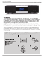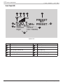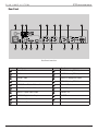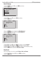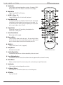
1
ELAN HOME SYSTEMS
DT22 INSTALLATION MANUAL
Read Information—All the safety and operating information should be read before the appliance is operated.
Follow Information—All operating and use information should be followed.
Retain Information—The safety and operating information should be retained for future reference.
Heed Warnings—All warnings on the appliance and in the operating instructions should be heeded.
Wall Mounting—Mounting of this appliance should be done only by an authorized installer.
Ventilation—The appliances should be situated so that their location or position does not interfere with their proper
ventilation. These appliances should never be placed near or over a radiator or heat register.
-These appliances should not be placed in a built-in installation such as a bookcase or cabinet that may impede the flow of air through the
ventilation openings.
Non-Use Periods—Appliances that are left unattended and unused for long periods of time should be de-energized.
Grounding or Polarization—Do not defeat the safety purpose of the polarized or grounding-type plug. A polarized
plug has two blades with one blade wider than the other blade. A grounding type plug has two blades and a third
grounding prong. The polarized wide blade and the third prong are provided for your safety. If the provided plug does
not fit your outlet, consult an electrician for replacement of the obsolete outlet.
Power Cord Protection—Protect the power cord from being walked on or pinched particularly at plugs, convenience
receptacles and the point where they exit from the apparatus.
Water—Do not use the apparatus near water.
© ELAN Home Systems 2009 • All rights reserved.
Page 3
DT22 INSTALLATION MANUAL
ELAN HOME SYSTEMS
Cleaning—Unplug the apparatus from the power outlet before cleaning. Use only a dry cloth to clean the apparatus.
Power Lines—An outdoor antenna should be located away from power lines. When installing an outside antenna.
system, extreme care should be taken to avoid touching power lines or circuits, as contact with them may be fatal.
Object and Liquid Entry—Never insert objects of any kind through the openings of these appliances, as they may
touch dangerous voltage points or short-out parts that could result in a fire or electric shock. Care should be taken so
that objects do not fall and liquids are not spilled into the appliance through openings in the enclosure.
Servicing—Do not attempt to service these appliances yourself, as opening or removing covers may expose you to
dangerous voltage or other hazards. Refer all servicing to qualified service personnel.
Damage Requiring Service—These appliances should be serviced by qualified service personnel when:
• A power supply connection or a plug has been damaged or
• If liquid has been spilled into the appliance or objects have fallen into the appliance or
• The appliance has been exposed to water or moisture or
• The appliance does not appear to operate normally or exhibits a marked change in performance or
• The appliance has been dropped or the enclosure damaged.
Replacement Parts—When replacement parts are required, be sure the service technician has used replacement
parts specified by the manufacturer or that have the same characteristics as the original part. Unauthorized substitutions
may result in fire, electric shock, or other hazards. The Master Control Unit battery should be replaced only after
turning the power off and only by an authorized installer.
Safety Check—Upon completion of any service or repairs to this audio product, ask the service technician to perform
safety checks to determine that the audio product is in proper operating condition.
Lightning Storms—Unplug this apparatus during lightning storms or when unused for long periods of time.
Attachments and Accessories—Use only attachments/accessories specified by the manufacturer.
Cart, Stand, Tripod, Bracket or Table—Use only with a cart, stand, tripod, bracket or table specified
by the manufacturer, or sold with the apparatus. When a cart is used, use caution when moving the
cart/apparatus combination to avoid injury from tip over.
Disconnect Device—Where the mains plug or an appliance coupler is used as the disconnect
device, the disconnect device shall remain operable.
NOTE:
This equipment has been tested and found to comply with the limits for a Class B digital device, pursuant to
part 15 of the FCC Rules. These limits are designed to provide reasonable protection against harmful interference in a
residential installation. This equipment generates, uses and can radiate radio frequency energy and, if not in-stalled
and used in accordance with the instructions, may cause harmful interference to radio communications. However,
there is no guarantee that interference will not occur in a particular installation. If this equipment does cause harmful
interference to radio or television reception, which can be determined by turning the equipment off and on, the user is
encouraged to try to correct the interference by one or more of the following measures:
• Reorient or relocate the receiving antenna.
• Increase the separation between the equipment and receiver.
• Connect the equipment into an outlet on a circuit different from that to which the receiver is connected.
• Consult the dealer or an experienced radio/TV technician for help.
CAUTION:
Changes or modifications not expressly approved by Elan Home Systems could void the user’s authority
to operate the equipment.
Page 4
© ELAN Home Systems 2009 • All rights reserved.
ELAN HOME SYSTEMS
DT22 INSTALLATION MANUAL
Table of Contents
Intro������������������������������������������������������������������������������������������������������������������������������������������������������������������������������������������ 8
Highlights.................................................................................................................................................................... 10
Items in package......................................................................................................................................................... 10
Front Panel (Hard Buttons)......................................................................................................................................... 11
Front Panel LCD.......................................................................................................................................................... 12
Rear Panel.................................................................................................................................................................. 13
Rack Mounting............................................................................................................................................................ 14
Connections�������������������������������������������������������������������������������������������������������������������������������������������������������������������������� 15
IR................................................................................................................................................................................ 15
RS-232........................................................................................................................................................................ 15
VIA!NET...................................................................................................................................................................... 16
Ethernet...................................................................................................................................................................... 17
RCA Audio.................................................................................................................................................................. 18
OPTICAL Audio........................................................................................................................................................... 18
AM Loop Antenna....................................................................................................................................................... 19
FM Antenna................................................................................................................................................................. 19
Rear Panel Power Switch............................................................................................................................................ 22
Operation������������������������������������������������������������������������������������������������������������������������������������������������������������������������������� 22
Front Panel.................................................................................................................................................................. 23
Mode Menu................................................................................................................................................................. 24
AM/FM........................................................................................................................................................ 24
Preset/Direct............................................................................................................................................... 24
Stereo/Mono............................................................................................................................................... 25
Saving Presets............................................................................................................................ 26
Deleting Presets.......................................................................................................................... 26
Override...................................................................................................................................................... 27
Change Custom Text................................................................................................................... 27
Remove Custom Text.................................................................................................................. 29
Changing Genre.......................................................................................................................... 30
Removing Genre Override........................................................................................................... 31
Details......................................................................................................................................................... 32
System Configuration................................................................................................................................................. 33
Unit ID........................................................................................................................................................ 33
LCD Settings............................................................................................................................................... 34
© ELAN Home Systems 2009 • All rights reserved.
Page 5
DT22 INSTALLATION MANUAL
ELAN HOME SYSTEMS
LCD Timeout............................................................................................................................... 35
LCD Contrast.............................................................................................................................. 36
LCD Brightness........................................................................................................................... 37
Front Panel IR............................................................................................................................................. 38
RS232......................................................................................................................................................... 39
Baud Rate................................................................................................................................... 39
Unsolicited Feedback.................................................................................................................. 40
Ethernet...................................................................................................................................................... 41
Configuration Type...................................................................................................................... 41
Static Parameters........................................................................................................................ 42
Show Current.............................................................................................................................. 45
ZNet Bridge................................................................................................................................................. 46
Region........................................................................................................................................................ 47
Version Info................................................................................................................................................ 48
Restore Defaults......................................................................................................................................... 49
Remote Control Operation���������������������������������������������������������������������������������������������������������������������������������������������� 50
Troubleshooting������������������������������������������������������������������������������������������������������������������������������������������������������������������� 52
Appendix A Specifications���������������������������������������������������������������������������������������������������������������������������������������������� 56
Appendix B: Serial Protocol������������������������������������������������������������������������������������������������������������������������������������������� 57
Port Configuration...................................................................................................................................................... 57
Messages.................................................................................................................................................................... 57
Unsolicited Feedback notifications.............................................................................................................................. 57
Query/Response Command Structure........................................................................................................................ 57
Dump Command Structure . ...................................................................................................................................... 58
Status Command Structure ....................................................................................................................................... 58
Command Structure.................................................................................................................................................... 58
<COMMAND>............................................................................................................................................................. 58
Power On/Off/Toggle................................................................................................................................................... 58
Select.......................................................................................................................................................................... 59
Display On.................................................................................................................................................................. 59
Reboot........................................................................................................................................................................ 59
Config......................................................................................................................................................................... 60
Config RS232 Unsolicited Feedback On/Off................................................................................................................ 61
UFB On/Off (Unsolicited Feedback)............................................................................................................................. 62
Boot Version............................................................................................................................................................... 63
Code Version.............................................................................................................................................................. 63
Page 6
© ELAN Home Systems 2009 • All rights reserved.
ELAN HOME SYSTEMS
DT22 INSTALLATION MANUAL
Mode: Direct/Preset.................................................................................................................................................... 63
Digit............................................................................................................................................................................ 64
Enter........................................................................................................................................................................... 64
Cancel......................................................................................................................................................................... 64
Group.......................................................................................................................................................................... 64
Preset.......................................................................................................................................................................... 65
MDF (Metadata Feedback).......................................................................................................................................... 67
Signal.......................................................................................................................................................................... 68
Scan............................................................................................................................................................................ 68
AM/FM Band............................................................................................................................................................... 69
Tune............................................................................................................................................................................ 69
Seek............................................................................................................................................................................ 70
Stereo......................................................................................................................................................................... 70
Appendix C: Adding SIRIUS Radio Functionality���������������������������������������������������������������������������������������������������� 72
Connecting the SIRIUS Tuner Module........................................................................................................................ 72
Displaying Signal Strength.......................................................................................................................................... 72
Connecting Audio Outputs.......................................................................................................................................... 72
Tuner Activation.......................................................................................................................................................... 72
Selecting the SIRIUS Tuner......................................................................................................................................... 73
Direct Mode Operation................................................................................................................................................ 73
Category Mode Operation........................................................................................................................................... 73
Preset Mode Operation............................................................................................................................................... 74
Recalling Presets........................................................................................................................................................ 74
Displaying SIRIUS Firmware Version and Product ID................................................................................................. 74
Viewing DT22 Firmware Version................................................................................................................................. 74
© ELAN Home Systems 2009 • All rights reserved.
Page 7
DT22 INSTALLATION MANUAL
ELAN HOME SYSTEMS
Introduction
Thank you for choosing the ELAN DT22 Dual AM/FM Tuner. The ELAN DT22 Dual Tuner is two AM/FM digital
tuners in one standard-sized audio component. Each tuner has its own audio output so that each may be listened
to independently. The DT22 features a total of 396 AM/FM presets plus 396 SIRIUS presets per chassis. When
used in conjunction with ELAN Touch Panels, the combination of Direct Access tuning and a plethora of Presets
makes control of the DT22 easy and intuitive – from anywhere in your home.
The DT22 includes a front panel IR receiver, full function handheld remote, and rear panel control ports for IR,
VIA!NET and serial control. Two-way feedback, including station call letters, frequency, genre, song name and artist, can be displayed on any ELAN Touch Panel or Olé Interactive Touchpad without the use of an SS1, SC1 or SC4.
With a 128 x 64 graphical LCD and front panel button access, the setup is easy. Through guided setup processes
including Network and Ethernet to a full diagnostics menu that includes signal strength and SIRIUS signal detection the DT22 allows the installation to be intuitive. Even the programming of favorite stations by the user is guided
to allow easy setup.
Page 8
NOTE: The SCH1 (sold separately) is all that is needed to add SIRIUS Satellite Radio to an ELAN DT22
Dual Tuner. Refer to Appendix C for detailed setup and use information.
© ELAN Home Systems 2009 • All rights reserved.
ELAN HOME SYSTEMS
DT22 INSTALLATION MANUAL
Listening to Satellite Radio
To listen to Satellite Radio, you’ll need to connect a SIRIUS-Ready receiver. SIRIUS Satellite Radio is available to
residents of the US (excluding Alaska and Hawaii) and Canada.
Satellite Radio delivers a variety of commercial-free music from categories ranging from Pop, Rock, Country, R&B,
Dance, Jazz, Classical and many more plus coverage of all top profesional and college sports including play by play
games from select leagues and teams. Additional programming includes expert sports talk, uncensored entertainment, comedy, family programming, local traffic and weather and news from your most trusted sources.
Once you’ve purchased a Sirius tuner you’ll need to activate it and subscribe to begin enjoying the service. Easy to
follow installation and setup instructions are provided with the SIRIUS tuner. There are a variety of programming
packages available, including the option of adding “The Best of XM” to the SIRIUS service enabling you to enjoy
the most popular programming among both services. Family friendly packages are also available to restrict channels featuring content that may be inappropriate for children.
To subscribe to SIRIUS, U.S. and Candian customers can call 1-888-539 SIRI (1-888-539-7474) or visit sirius.com
(US) or siriuscanada.ca (Canada).
SIRIUS, XM and all related marks and logos are trademarks of SIRIUS XM Radio Inc. and its subsidiaries. All other marks and logos are the
property of their respective owners. All rights reserved. SIRIUS subscription sold seperately. Taxes and a one-time activation fee may apply.
SIRIUS tuner required (sold seperately) to receive the SIRIUS service. All programming and fees subject to change. It is prohibited to copy,
decompile, reverse engineer, hack, manipulate or otherwise make available any technology or software incorporated in receivers compatible
with the SIRIUS Satellite Radio System. Service not available in Alaska or Hawaii.
© ELAN Home Systems 2009 • All rights reserved.
Page 9
DT22 INSTALLATION MANUAL
ELAN HOME SYSTEMS
Product Highlights
• Two AM/FM Digital Tuners
• Satellite Radio Ready. Add one or two SIRIUS Tuner Modules (sold separately)
• Four Sets of independent Outputs for Multi-Room Listening
• Link Two DT22s to Provide Up to 4 AM/FM Tuners and 4 SIRIUS Tuners
• Preset or Direct Numeric Access
• 4 Preset Groups labeled A, B, C, and D for easy preset organization.
• 99 flexible presets in each group. Each preset can hold either an AM, FM, or SIRIUS station.
• 396 Presets shared across 2 AM/FM Tuners plus 396 Presets shared across 2 SIRIUS Tuners.
• Easy Setup and Diagnostics With Front Panel Buttons and Graphical LCD
• View Radio Station & “Now Playing” RDS information on ELAN User interfaces (EM version VIA! panels
only)
• VIA!NET, Ethernet, Serial and IR Controllable.
• Use With Any ELAN Wireless Touch Panel, Olé Touch Pad, or EM version LCD Touch Panel.
• New ELAN SmartSource (Does not require a System SS1, SC1 or SC4 for Two-Way Feedback)
• Displays RDS (Radio Data System)
• cTUVus Certified, CE®, CB Scheme, FCC part 15, and C-tick
Items in package
• DT22 Tuner
• Rack Mount Brackets
• DT22 Remote Control
• AM Loop Antenna
• FM Antenna
• Installation Manual
• AC line cord
• SIRIUS Tuner Modules sold separately
Page 10
© ELAN Home Systems 2009 • All rights reserved.
DT22 INSTALLATION MANUAL
ELAN HOME SYSTEMS
Front Panel (Hard Buttons)
2
1
3
4
6
5
DT22 Front Panel Controls & Indicators
Item
Name
Item
Name
1
Tuner Select Button
4
Power LED
2
Mode Button
5
Memory Button
3
Navigation Arrows and Enter Button
6
Access Door (Shown Open)
© ELAN Home Systems 2009 • All rights reserved.
Page 11
DT22 INSTALLATION MANUAL
ELAN HOME SYSTEMS
Front Panel LCD
1
Y
6
7
2
3
5
4
ST
FM1
100.1
PRESET
B01
MHZ PRESET
XXXX ROCK
Cathexis
Dark of
Night
100.1 WKRQ
10
9
8
Graphical LCD
Item#
Function
Item#
Function
1
Signal Indicator
6
Station Frequency
2
Stereo Indicator
7
Custom Text
3
Signal Strength Indicator Bar
8
RDS Radio Text
4
Tuner Mode Indicator
9
Station Genre/Category
5
Current Tuned Preset
10
Preset/Direct/Category Mode
Page 12
© ELAN Home Systems 2009 • All rights reserved.
DT22 INSTALLATION MANUAL
ELAN HOME SYSTEMS
Rear Panel
1
2
3
19
18
17
4
16
6
5
15
14
7
8
12
13
9
11
10
Rear Panel Connections
Item#
Function
Item #
Function
1
Power Switch
11
AM/FM 2 Analog RCA Output
2
IR IN
12
AM/FM 1 Analog RCA Output
3
VIA!NET Input
13
SIRIUS 2 Analog RCA Output
4
B1 Button
14
SIRIUS 1 Analog RCA Output
5
SIRIUS Tuner Module 1 Connection
15
Ethernet Port
6
SIRIUS Tuner Module 2 Connection
16
RS-232 Port
7
AM/FM 1 Digital Audio Output
17
VIA!NET Out
8
AM/FM 2 Digital Audio Output
18
IR OUT
9
AM Antenna Connector
19
Power Inlet/Fuse Holder
10
FM Antenna Connector
© ELAN Home Systems 2009 • All rights reserved.
Page 13
DT22 INSTALLATION MANUAL
ELAN HOME SYSTEMS
Rack Mounting
When mounting the DT22 Tuner in an equipment rack, use the included Rack Mount Brackets for secure mounting
and proper ventilation. The DT22 requires two rack spaces.
To install the DT22 into a standard 19” equipment rack:
1. Slide the rack mount brackets onto the DT22 chassis from the front as shown in Figure 14-1.
2. Ensure that the brackets are flush with the front of the unit. Install each of the eight screws (included) through
the side mounting flanges into the holes in the sides of the unit as shown in Figure 14-2. Hand tighten screws!
Over-tightening could cause damage to the DT22 Tuner.
3. Once the brackets are securely mounted, install the entire assembly into a standard 19” equipment rack from the
front using four rack screws (not included). Two rack spaces will be used. See Figure 14-3.
19" Equipment Rack
Rack Screws
Page 14
© ELAN Home Systems 2009 • All rights reserved.
DT22 INSTALLATION MANUAL
ELAN HOME SYSTEMS
Connections
IR
The DT22 can be controlled using the 3.5mm (‘mini’) IR jack on the back panel. There is also an 3.5mm IR Loop
Output jack included to connect to additional DT22s.
S128P
DT22 #1
TO Second
DT22 IR IN
S128P Source IR Out to DT22 IR Loop Connections
RS-232
The RS232 port on the back of the unit is used to connect the DT22 to a computer to facilitate firmware updates
and download tuner configuration parameters for troubleshooting.
It can also be used to control Direct and Preset features.
DT22
1
6
DB9 CABLE
FROM COMPUTER
RS-232 Connection
© ELAN Home Systems 2009 • All rights reserved.
Page 15
DT22 INSTALLATION MANUAL
ELAN HOME SYSTEMS
VIA!NET
Use the VIA!NET ports when controlling the DT22 with ELAN Touch Panels, SC-1 Serial Controller, SS1 System
Station and/or other VIA!NET devices. The VIA!NET ports on the DT22 can be daisy-chained between chassis and
other VIA!NET devices.
Use an RJ-45 to RJ-45 interconnect cable to make all VIA!NET connections.
Use the following diagram when connecting a S86A/S86P and not using an SPP.
VIA!NET Connections
If there is not a System SS1 or System SC1 in the system, make the following connections.
VIA!NET Connections
Page 16
© ELAN Home Systems 2009 • All rights reserved.
DT22 INSTALLATION MANUAL
ELAN HOME SYSTEMS
If a System SS1 or System SC1 is in the system, use the following connections.
To
SS1/SC1
VIA!NET
Connector
VIA!NET Loop Connection
Ethernet
The ETHERNET port can be used to connect the DT22 to a LAN (Local Area Network) connection for Firmware
Updates. It may also be used by supported software applications to communicate with the DT22. An Ethernet
cable wired to T568A (or T568B) should be used in conjunction with this connection.
DT22
1 2 3 4 5 6 7 8
T568A WIRING STANDARD
BROWN/WHITE
BROWN
BLUE/WHITE
ORANGE
ORANGE/WHITE
BLUE
ETHERNET
CABLE
GREEN/WHITE
GREEN
1 2 3 4 5 6 78
T568A Ethernet Connection
© ELAN Home Systems 2009 • All rights reserved.
Page 17
DT22 INSTALLATION MANUAL
ELAN HOME SYSTEMS
RCA Audio
Using RCA-type interconnect cables, connect all active tuner audio outputs to pairs of inputs on an ELAN preamp
controller (e.g. S66A, S86A/P, S128P or to a stereo receiver). Make sure to connect Left channel outputs to Left
channel inputs and Right channel outputs to Right channel inputs.
S128P
RCA PATCH
CABLES
DT22
L
R
RCA Audio Connections
OPTICAL Audio
Using an Optical interconnect cable, connect TUNER 1 and/or TUNER 2 Optical output(s) to any Optical input(s) on
a Stereo Receiver, Digital Audio Wallplate, or Home Theater Receiver.
Digital Optical
Input
DT22
Digital
Optical
Cable
OPTICAL Audio Connections
Page 18
© ELAN Home Systems 2009 • All rights reserved.
DT22 INSTALLATION MANUAL
ELAN HOME SYSTEMS
AM Loop Antenna
DT22
AM Loop Antenna
The AM antenna is connected to the terminals marked AM/GND. These connections are not polarity sensitive, so it
does not matter which wire is connected to the GND or AM terminals.
To prevent unwanted noise, place the antenna as far away as possible from other electronics, speaker cords, power
cords and amplifiers.
FM Antenna
DT22-240
REAR PANEL
F-JACK
F-CONNECTOR
Indoor FM Antenna
Connect the included FM antenna to the FM (coaxial) jack. Generally, a T-type twin lead antenna will be sufficient; if
you live in an area where the FM signals are particularly weak, it may be necessary to install an outside or rooftop
antenna.
If standard FM broadcast frequencies are available via your cable service, you may connect your 75 ohm FM antenna jack to your cable system. Please contact your cable service to discuss this option.
© ELAN Home Systems 2009 • All rights reserved.
Page 19
DT22 INSTALLATION MANUAL
ELAN HOME SYSTEMS
SIRIUS Tuner Module Connections
R
AUDIO
OUT
L
8 PIN
OPTICAL
2
3
1
Front Panel Connections
Item
Name
1
Analog Audio Out (not used)
2
8 Pin DIN -- Connects to DT22
3
Optical Connection
DC 5V
ANT
1
2
Rear Panel Connections
Item
Name
1
5 VDC power connection (not used)
2
Satellite Antenna Connection
Page 20
© ELAN Home Systems 2009 • All rights reserved.
DT22 INSTALLATION MANUAL
ELAN HOME SYSTEMS
SIRIUS Satellite Antenna
Positioning the Sirius Antenna
Prior to mounting the antenna or finding a permanent home for your DT22, you first want to
validate the position of the antenna.
1. Power on DT22 to make sure the SIRIUS module has power.
You should see a startup screen with the ELAN logo, followed by the main display.
2. Power off DT22, and then connect the audio cables, IR, and RS232 control interfaces to the other components
in your audio system.
3. Align the Antenna as follows:
For Indoor installation on a flat surface:
a) Set antenna on its base on a flat horizontal surface.
b) Turn the base of the antenna so that the SIRIUS logo is facing to the northwest if you are in the eastern
half of the U.S. and to the north/northeast if you are in the western half.
Note: It will help to imagine that the SIRIUS satellites are in the sky above northern Minnesota.
That’s the optimal direction in which you need to aim the antenna.
c) Use the “Signal Strength” screen, as described on page 74, to optimize antenna tilt angle and position.
d) If necessary, experiment with different locations near a north-facing window or outside.
© ELAN Home Systems 2009 • All rights reserved.
Page 21
DT22 INSTALLATION MANUAL
ELAN HOME SYSTEMS
For outdoor installation or indoor wall mounting:
The antenna can also be attached vertically to an external or internal wall if that is more convenient than placing it
on a horizontal surface.
a) Holding your antenna up, find a wall location that ensures a strong signal.
b) Attach antenna to the wall using four screws.
c) Tilt the antenna fully back on the base, place the antenna base on the four screw heads with the antenna
pivot at the top, and pull down approximately 1/4 inch until the base is firmly secured. Note that the
SIRIUS logo will be upside down when the antenna is properly installed.
d) Tilt the antenna away from the wall/base until the signal strength is optimized.
4. Power on your sound system and turn the amplifier to a low volume.
5. Power on DT22 and tune to channel 184, a free preview channel.
If the system is working, you will hear SIRIUS programming on this channel and can proceed to Step 6.
If there is a problem with the antenna connection, the DT22’s front panel display will read “Antenna Error”. If
the antenna does not have a clear path to the satellites, the front panel display will read “Acquiring Signal”.
Reposition the antenna until you hear music playing.
6. Finish installing DT22.
a) House DT22 in its permanent location. Follow the instructions in the section, “Appendix B: Rack
Mounting”.
b) Activate the unit following the “Activating SIRIUS radio” instructions.
Rear Panel Power Switch
The DT22 master power switch is located on the rear panel. The switch must be in the ON position to allow the
tuner to operate. To reduce power consumption when away for extended periods of time, set the master switch to
the OFF position. To return tuner to normal operation, set the switch to the ON position.
Rear Panel Power Switch
Operation
The DT22 provides intuitive control of its various functions via its front panel buttons (as shown on the next page),
from ELAN Touch Panels and Olé Touchpads, the remote control, and its hard wired IR input. The DT22 is essentially two completely independent AM-FM radio tuners (add another DT22 for a total of four)—each of which can
be tuned independently so that different audio channels play in different rooms.
From the interface within each zone you can:
Page 22
•
•
Change channels (either by preset or direct tuning)
View RDS information (on supported panels)
© ELAN Home Systems 2009 • All rights reserved.
DT22 INSTALLATION MANUAL
ELAN HOME SYSTEMS
Default Display
The default display, as shown below, provides information about the channel each tuner is currently tuned to,
including category name, channel number, channel name, artist name, and song title.
Y
ST
FM1
100.1 MH
PRESET
B01
Z PRESET
ROCK
Cathexis
Dark of
Night
100.1 WKRQ
LCD Display
Front Panel
D
A
B
E
E
F
D
C
Front Panel Controls
A. TUNER
• Switches between Tuner 1, Tuner 2, SIRIUS 1 and SIRIUS 2.
• Press and Hold to turn the DT22 On or Off.
B. MODE
• Displays the Mode Menu on the LCD that allows settings - AM/FM, Preset/Direct/Stereo/Mono - to be changed using
Arrow Up/Down buttons without the use of a remote.
C. MEMORY
• Displays the Memory Menu on the LCD that allows Presets to be either saved or deleted using Arrow Up/Down buttons without the use of a remote; each Group (A,B,C,D) has 99 presets.
© ELAN Home Systems 2009 • All rights reserved.
Page 23
DT22 INSTALLATION MANUAL
ELAN HOME SYSTEMS
D. ARROW Up/Down
• Use these buttons to Seek after the Tuner button is pressed, navigate the Mode On-Screen-Display after the Mode button is pressed or navigate the Memory On-Screen-Display after the Memory button is pressed.
E. ARROW Left/Right Buttons
• Use these buttons to Increment/Decrement or Step the frequency after the Tuner button is pressed, do nothing after
the Mode button is pressed.
F. F ENTER Button
• Use this button to verify or confirm an intended operation or function.
•
In AM/FM, the button is used to bring up overrides, details, exit, in SIRIUS it cycles through data
Mode Menu
Mode Menu submenus:
• AM/FM
• Preset/Direct
• Stereo/Mono
AM/FM
1) Toggle the Band from AM to FM or from FM to AM.
2) Press the MODE button.
3) Highlight AM/FM using the UP arrow or DOWN arrow buttons.
4) Press the ENTER button.
Y
ST
FM1
100.1 MH
AM/FM
Preset/Direct
Stereo/Mono
PRESET
Z
B01
PRESET
Preset/Direct
Places the Tuner in Preset or Direct mode.
Direct places the tuner in Direct mode.
Preset places the tuner in Preset with the current selected Group selected.
Preset Group A places the Tuner in Preset mode and changes the Tuner to Group A.
Preset Group B places the Tuner in Preset mode and changes the Tuner to Group B.
Preset Group C places the Tuner in Preset mode and changes the Tuner to Group C.
Preset Group D places the Tuner in Preset mode and changes the Tuner to Group D.
No preset exists for the tuned frequency if “--” is displayed after the group, like it is in the following image “B--”.
Page 24
© ELAN Home Systems 2009 • All rights reserved.
DT22 INSTALLATION MANUAL
ELAN HOME SYSTEMS
1) Press the MODE button.
2) Highlight Preset/Direct using the UP arrow or DOWN arrow buttons.
3) Press the ENTER button.
Y
ST
FM1
100.1 MH
AM/FM
Preset/Direct
Stereo/Mono
PRESET
Z
B01
PRESET
1) Highlight Direct, Preset, Preset Group A, Preset Group B, Preset Group C, or Preset Group D using the UP
arrow or DOWN arrow buttons.
2) Press the ENTER button when done.
Z
PRESET
Stereo/Mono
This menu selection switches the FM signal between stereo and mono. Switching to mono mode can make weak
FM signals sound clearer.
The Stereo icon will be displayed when in Stereo mode and absent when in Mono mode.
1) Press the MODE button.
2) Highlight Stereo/Mono using the UP arrow or DOWN arrow buttons.
3) Press the ENTER button.
© ELAN Home Systems 2009 • All rights reserved.
Page 25
DT22 INSTALLATION MANUAL
Y
ST
ELAN HOME SYSTEMS
Stereo Icon
FM1
100.1 MH
AM/FM
Preset/Direct
Stereo/Mono
PRESET
Z
C01
PRESET
Saving Presets
Select one of the four Preset Groups A-D.
1) Tune to a station that is going to be saved.
2) Press the MEMORY button.
3) Highlight Save Preset using the UP arrow or DOWN arrow buttons.
4) Press the ENTER button.
Y
ST
FM1
100.1 MH
PRESET
Z
Save Preset
Delete Preset
EXIT
A01
PRESET
1) Press the UP/DOWN arrows to change the first Preset digit.
2) Press the LEFT/RIGHT arrows select the second Preset digit.
3) Press the UP/DOWN arrows to change the second Preset digit.
4) Press the Enter button when done.
1) Highlight Save using the UP arrow or DOWN arrow buttons to save the change.
2) Highlight Cancel using the UP arrow or DOWN arrow buttons to revert to the previous setting.
3) Highlight Edit using the UP arrow or DOWN arrow buttons to change the preset digits.
4) Press the ENTER button to commit the selection Edit, Save or Cancel.
Deleting Presets
1) Select a preset that will be deleted.
Page 26
© ELAN Home Systems 2009 • All rights reserved.
DT22 INSTALLATION MANUAL
ELAN HOME SYSTEMS
2) Press the MEMORY button.
3) Highlight Delete Preset using the UP arrow or DOWN arrow buttons.
4) Press the ENTER button.
Y
ST
FM1
100.1 MH
PRESET
Z
Save Preset
Delete Preset
EXIT
A01
PRESET
1) Highlight Delete using the UP arrow or DOWN arrow buttons to delete the preset.
2) Highlight Cancel using the UP arrow or DOWN arrow buttons to abort the delete.
3) Press the ENTER button to commit either Delete or Cancel.
Override
Change Custom Text
The DT22 provides the ability to override a station’s Custom Text.
1) Ensure the Tuner is On.
2) Select a station whose Call Sign you want to change.
3) Press the ENTER button.
4) Highlight Override using the UP arrow or DOWN arrow buttons.
5) Press the ENTER button.
1) Highlight Call Sign using the UP arrow or DOWN arrow buttons.
2) Press the ENTER button.
© ELAN Home Systems 2009 • All rights reserved.
Page 27
DT22 INSTALLATION MANUAL
Y
ST
ELAN HOME SYSTEMS
FM1
100.1 MH
PRESET
Z
Call Sign
Genre
EXIT
D01
PRESET
1) Highlight Edit using the UP arrow or DOWN arrow buttons.
2) Press the Enter button.
Y
ST
FM1
100.1 MH
Z
CURRENT: ‘WKQQ’
Edit
Remove Edits
EXIT
PRESET
D01
PRESET
1) Press the UP/DOWN arrows to change the characters.
2) Press the LEFT/RIGHT arrows select the next character.
3) Press the Enter button when done.
Y
ST
FM1
100.1 MH
CURRENT:
Edit
Save
Cancel
Z
‘WKQQ’
PRESET
D01
PRESET
1) Highlight Save using the UP arrow or DOWN arrow buttons to save the change.
2) Highlight Cancel using the UP arrow or DOWN arrow buttons to revert the previous setting.
3) Highlight Edit using the UP arrow or DOWN arrow buttons to change the Call Sign characters.
4) Press the ENTER button to commit either Edit, Save or Cancel.
See next page for example
Page 28
© ELAN Home Systems 2009 • All rights reserved.
DT22 INSTALLATION MANUAL
ELAN HOME SYSTEMS
Y
ST
FM1
PRESET
100.1 MH
CURRENT:
Edit
Save
Cancel
Z
‘WKRQ’
D01
PRESET
Remove Custom Text
1) Ensure the Tuner is On.
2) Select a station whose Custom Text you want to remove.
3) Press the ENTER button.
4) Highlight Override using the UP arrow or DOWN arrow buttons.
5) Press the ENTER button.
1) Highlight Call Sign using the UP arrow or DOWN arrow buttons.
2) Press the ENTER button.
Y
ST
FM1
100.1 MH
PRESET
Z
Call Sign
Genre
EXIT
D01
PRESET
1) Highlight Remove Edits using the UP arrow or DOWN arrow buttons.
2) Press the ENTER button.
See next page for example
© ELAN Home Systems 2009 • All rights reserved.
Page 29
DT22 INSTALLATION MANUAL
Y
ST
ELAN HOME SYSTEMS
FM1
PRESET
100.1 MH
Z
‘WLRQ’
CURRENT:
Edit
Remove Edits
EXIT
D01
PRESET
Changing Genre
The DT22 provides the ability to change a station’s Genre.
1) Ensure the Tuner is On.
2) Select a station whose Genre you want to change.
3) Press the ENTER button.
4) Highlight Override using the UP arrow or DOWN arrow buttons.
5) Press the ENTER button.
1) Highlight Genre using the UP arrow or DOWN arrow buttons.
2) Press the ENTER button.
Y
ST
FM1
100.1 MH
Call Sign
Genre
EXIT
PRESET
Z
D01
PRESET
1) Highlight Edit using the UP arrow or DOWN arrow buttons.
2) Press the ENTER button.
See next page for example
Page 30
© ELAN Home Systems 2009 • All rights reserved.
DT22 INSTALLATION MANUAL
ELAN HOME SYSTEMS
Y
ST
FM1
100.1 MH
‘ Rock
Edit
Save
Cancel
PRESET
Z
D01
PRESET
’
Press the UP/DOWN arrows to change the Genre.
Press the ENTER button when done.
Y
ST
FM1
100.1 MH
‘ Rock
Edit
Save
Cancel
PRESET
Z
D01
PRESET
’
1) Highlight Edit using the UP arrow or DOWN arrow buttons to change the Genre.
2) Highlight Save using the UP arrow or DOWN arrow buttons to save the change.
3) Highlight Cancel using the UP arrow or DOWN arrow buttons to revert the previous setting.
4)Press the ENTER button to commit either Edit, Save or Cancel.
Y
ST
FM1
100.1 MH
‘ Rock
Edit
Save
Cancel
PRESET
Z
D01
PRESET
’
Removing Genre Override
The DT22 provides the ability to remove a station’s Genre Override.
1) Ensure the Tuner is On.
2) Select a station whose Genre Override you want to remove.
3) Press the ENTER button.
4) Highlight Override using the UP arrow or DOWN arrow buttons.
5) Press the ENTER button.
See next page for example
© ELAN Home Systems 2009 • All rights reserved.
Page 31
DT22 INSTALLATION MANUAL
ELAN HOME SYSTEMS
1) Highlight Genre using the UP arrow or DOWN arrow buttons.
2) Press the ENTER button.
Y
ST
FM1
100.1 MH
PRESET
Z
Call Sign
Genre
EXIT
D01
PRESET
1) Highlight Remove Edits using the UP arrow or DOWN arrow buttons.
2) Press the ENTER button.
Y
ST
FM1
100.1 MH
Z
‘WLRQ’
CURRENT:
Edit
Remove Edits
EXIT
PRESET
D01
PRESET
Once the Enter button is pressed, the associated Genre Override is removed.
Details
If it is suspected that the DT22 has tuner performance issues, a diagnostic tool is provided to give feedback to the
installer in conjunction with a troubleshoot call with ELAN Technical Support.
1) Ensure the Tuner is On.
2) Select a station whose Details you want to see.
3) Press the ENTER button.
4) Highlight Details using the UP arrow or DOWN arrow buttons.
5) Press the ENTER button.
See next page for example
Page 32
© ELAN Home Systems 2009 • All rights reserved.
DT22 INSTALLATION MANUAL
ELAN HOME SYSTEMS
Y
ST
FM1
100.1 MH
PRESET
Z
Override
Details
EXIT
B01
PRESET
Details are listed for the selected station.
FM1
100.1
:
Valid
:
Soft Mute
:
Pilot
:
Blend
:
RSSI
:
SNR
:
F Offset
TRUE
off
PRESENT
5%
32 dBuV
19 dB
-16 kHz
6) To Exit press any button.
System Configuration
If the Unit is On, turn it Off:
1) Press and Hold the TUNER button on the Front Panel to turn the unit Off.
or Press the Off button on the Remote.
2) Simultaneously Press and Hold both the LEFT and RIGHT front panel buttons.
Unit ID
The DT22 can provide Two-Way feedback status over VIA!NET to Elan Control Panels without the use of a SC1,
SS1 or SC4. The DT22 must be assigned an Unit ID when connected to the VIA!NET so it can be identified. There
can only be two DT22s connected to the VIA!NET.
By default the DT22 is shipped configured to Unit ID 1. For installations with only one DT22, this setting should
not be changed. However, when adding a second DT22 this setting must be changed to 2 on the second unit
NOTE: The VIA!NET jack on the back of the DT22 must be used.
1) Highlight Unit ID using the UP arrow or DOWN arrow buttons.
2) Press the ENTER button.
See next page for example
© ELAN Home Systems 2009 • All rights reserved.
Page 33
DT22 INSTALLATION MANUAL
DT22
ELAN HOME SYSTEMS
SETUP
MENU
Unit ID
LCD Settings
Front Panel IR
RS232
Ethernet
1) Highlight Edit using the UP arrow or DOWN arrow buttons.
2) Press the ENTER button.
1) Press the UP/DOWN arrows to change the Unit ID.
2) Press the Enter button when done.
3) Highlight Edit using the UP arrow or DOWN arrow buttons to change the Unit ID.
4) Highlight Save using the UP arrow or DOWN arrow buttons to save the change.
5) Highlight Cancel using the UP arrow or DOWN arrow buttons to revert the previous setting.
6) Press the ENTER button to commit either Edit, Save or Cancel.
LCD Settings
LCD settings can be changed to provide optimum readability in various lighting conditions.
LCD Settings submenus:
•
•
Page 34
LCD Timeout
LCD Contrast
© ELAN Home Systems 2009 • All rights reserved.
DT22 INSTALLATION MANUAL
ELAN HOME SYSTEMS
•
LCD Brightness
1) Highlight LCD Settings using the UP arrow or DOWN arrow buttons.
2) Press the ENTER button.
MENU
DT22
SETUP
Unit ID
LCD Settings
Front Panel IR
RS232
Ethernet
LCD Timeout
This is the amount of time that the front panel’s LCD backlight is active after a Front Panel button press.
NOTE: It is possible to set the LCD Timeout value to ‘DISABLED’. This will prevent the LCD backlight from ever
turning off. It is recommended to greatly decrease the LCD Brightness if this value is used. Otherwise the lifetime
of the LCD backlight will be reduced.
1) Highlight LCD Timeout using the UP arrow or DOWN arrow buttons.
2) Press the ENTER button.
DT22
SETUP
LCD Settings
LCD Timeout
LCD Contrast
LCD Brightness
EXIT
MENU
1) Highlight Edit using the UP arrow or DOWN arrow buttons.
2) Press the ENTER button.
1) Press the UP/DOWN arrows to change the LCD Timeout time.
2) Press the ENTER button when done.
© ELAN Home Systems 2009 • All rights reserved.
See next page for example
Page 35
DT22 INSTALLATION MANUAL
ELAN HOME SYSTEMS
1) Highlight Edit using the UP arrow or DOWN arrow buttons to change the LCD Timeout.
2) Highlight Save using the UP arrow or DOWN arrow buttons to save the change.
3) Highlight Cancel using the UP arrow or DOWN arrow buttons to revert the previous setting.
4) Press the ENTER button to commit either Edit, Save or Cancel.
LCD Contrast
1) Highlight LCD Contrast using the UP arrow or DOWN arrow buttons.
2) Press the ENTER button.
DT22
SETUP
LCD Settings
LCD Timeout
LCD Contrast
LCD Brightness
EXIT
MENU
1) Highlight Edit using the UP arrow or DOWN arrow buttons.
2) Press the ENTER button.
1) Press the UP/DOWN arrows to change the LCD Contrast.
2) Press the ENTER button when done.
See next page for example
Page 36
© ELAN Home Systems 2009 • All rights reserved.
DT22 INSTALLATION MANUAL
ELAN HOME SYSTEMS
1) Highlight Edit using the UP arrow or DOWN arrow buttons to change the LCD Contrast.
2) Highlight Save using the UP arrow or DOWN arrow buttons to save the change.
3) Highlight Cancel using the UP arrow or DOWN arrow buttons to revert the previous setting.
4) Press the ENTER button to commit either Edit, Save or Cancel.
LCD Brightness
1) Highlight LCD Brightness using the UP arrow or DOWN arrow buttons.
2) Press the ENTER button.
DT22
SETUP
LCD Settings
LCD Timeout
LCD Contrast
LCD Brightness
EXIT
MENU
1) Highlight Edit using the UP arrow or DOWN arrow buttons.
2) Press the ENTER button.
1) Press the UP/DOWN arrows to change the LCD Brightness.
2) Press the ENTER button when done.
See next page for example
© ELAN Home Systems 2009 • All rights reserved.
Page 37
DT22 INSTALLATION MANUAL
ELAN HOME SYSTEMS
1) Highlight Edit using the UP arrow or DOWN arrow buttons to change the LCD Brightness.
2) Highlight Save using the UP arrow or DOWN arrow buttons to save the change.
3) Highlight Cancel using the UP arrow or DOWN arrow buttons to revert the previous setting.
4) Press the ENTER button to commit either Edit, Save or Cancel.
Front Panel IR
Enables or disables the IR receiver located on the front panel.
You may want to disable if you experience IR flooding of the front sensor.
1) Highlight Front Panel IR using the UP arrow or DOWN arrow buttons.
2) Press the ENTER button.
DT22
SETUP
MENU
Unit ID
LCD Settings
Front Panel IR
RS232
Ethernet
1) Highlight Edit using the UP arrow or DOWN arrow buttons.
2) Press the ENTER button.
1) Press the UP/DOWN arrows to Enable or Disable Front Panel IR.
2) Press the ENTER button when done.
See next page for example
Page 38
© ELAN Home Systems 2009 • All rights reserved.
DT22 INSTALLATION MANUAL
ELAN HOME SYSTEMS
1) Highlight Edit using the UP arrow or DOWN arrow buttons to ENABLE or DISABLE Front Panel IR.
2) Highlight Save using the UP arrow or DOWN arrow buttons to save the change.
3) Highlight Cancel using the UP arrow or DOWN arrow buttons to revert the previous setting.
4) Press the ENTER button to commit either Edit, Save or Cancel.
RS232
RS232 Menu submenus:
•
•
Baud Rate
Unsolicited Feedback
1) Highlight RS232 using the UP arrow or DOWN arrow buttons.
2) Press the ENTER button.
DT22
SETUP
MENU
Unit ID
LCD Settings
Front Panel IR
RS232
Ethernet
Baud Rate
1) Highlight Baud Rate using the UP arrow or DOWN arrow buttons.
2) Press the ENTER button.
DT22
SETUP
MENU
RS232 SETTINGS
Baud Rate
Unsolicited Feedback
EXIT
© ELAN Home Systems 2009 • All rights reserved.
Page 39
DT22 INSTALLATION MANUAL
ELAN HOME SYSTEMS
1) Highlight Edit using the UP arrow or DOWN arrow buttons.
2) Press the ENTER button.
1) Press the UP/DOWN arrows to change the Baud Rate.
2) Press the ENTER button when done.
1) Highlight Edit using the UP arrow or DOWN arrow buttons to change the Baud Rate.
2) Highlight Save using the UP arrow or DOWN arrow buttons to save the change.
3) Highlight Cancel using the UP arrow or DOWN arrow buttons to revert the previous setting.
4) Press the ENTER button to commit either Edit, Save or Cancel.
Unsolicited Feedback
The DT22 can automatically send its status whenever its state changes. This is enabled by default.
1) Highlight Unsolicited Feedback using the UP arrow or DOWN arrow buttons.
2) Press the ENTER button.
DT22
SETUP
MENU
RS232 SETTINGS
Baud Rate
Unsolicited Feedback
EXIT
1) Highlight Edit using the UP arrow or DOWN arrow buttons.
2) Press the ENTER button.
See next page for example
Page 40
© ELAN Home Systems 2009 • All rights reserved.
ELAN HOME SYSTEMS
DT22 INSTALLATION MANUAL
1) Press the UP/DOWN arrows to Enable or Disable Unsolicited Feedback.
2) Press the ENTER button when done.
1) Highlight Edit using the UP arrow or DOWN arrow buttons to ENABLE or DISABLE Unsolicited Feedback.
2) Highlight Save using the UP arrow or DOWN arrow buttons to save the change.
3) Highlight Cancel using the UP arrow or DOWN arrow buttons to revert the previous setting.
4) Press the ENTER button to commit either Edit, Save or Cancel.
Ethernet
Ethernet Menu submenus:
• Configuration Type
• Show Current
To enter the Ethernet settings menu use the DOWN arrow to highlight Ethernet and press the ENTER button.
DT22
SETUP
MENU
LCD Settings
Front Panel
RS232
Ethernet
ZNet
Configuration Type
The Configuration Type settings menu allows the DT22 to be set to DHCP or Static IP Address.
1) Highlight Configuration Type using the UP arrow or DOWN arrow buttons.
2) Press the ENTER button.
See next page for example
© ELAN Home Systems 2009 • All rights reserved.
Page 41
DT22 INSTALLATION MANUAL
ELAN HOME SYSTEMS
DT22
SETUP
MENU
ETHERNET SETTINGS
Configuration Type
Show Current
EXIT
1) Highlight Edit using the UP arrow or DOWN arrow buttons.
2) Press the ENTER button.
1) Press the UP/DOWN arrows to select DHCP or Static.
2) Press the ENTER button when done.
1) Highlight Edit using the UP arrow or DOWN arrow buttons to change Configuration Type.
2) Highlight Save using the UP arrow or DOWN arrow buttons to save the change.
3) Highlight Cancel using the UP arrow or DOWN arrow buttons to revert the previous setting.
4) Press the ENTER button to commit either Edit, Save or Cancel.
Static Parameters
Static Parameters Menu submenus:
• IP Address
• Netmask
• Gateway
When STATIC is selected as a configuration type a hidden menu selection called Static Parameters appears.
Page 42
© ELAN Home Systems 2009 • All rights reserved.
ELAN HOME SYSTEMS
DT22 INSTALLATION MANUAL
1) Highlight Static Parameters using the UP arrow or DOWN arrow buttons.
2) Press the ENTER button.
DT22
SETUP
MENU
ETHERNET SETTINGS
Configuration Type
Static Parameters
Show Current
EXIT
STATIC IP ADDRESS
1) Highlight IP Address using the UP arrow or DOWN arrow buttons.
2) Press the ENTER button.
DT22
SETUP
MENU
STATIC IP SETTINGS
IP Address
Netmask
Gateway
EXIT
1) Highlight Edit using the UP arrow or DOWN arrow buttons.
2) Press the ENTER button.
1) Press the UP/DOWN arrows to change the IP Address digit.
2) Press the LEFT/RIGHT arrows select the next IP Address digit.
3) Press the ENTER button when done.
© ELAN Home Systems 2009 • All rights reserved.
Page 43
DT22 INSTALLATION MANUAL
ELAN HOME SYSTEMS
1) Highlight Edit using the UP arrow or DOWN arrow buttons to change IP Address.
2) Highlight Save using the UP arrow or DOWN arrow buttons to save the change.
3) Highlight Cancel using the UP arrow or DOWN arrow buttons to revert the previous setting.
4) Press the ENTER button to commit either Edit, Save or Cancel.
Static Netmask
1) Highlight Netmask using the UP arrow or DOWN arrow buttons.
2) Press the ENTER button.
DT22
SETUP
MENU
STATIC IP SETTINGS
IP Address
Netmask
Gateway
EXIT
1) Highlight Edit using the UP arrow or DOWN arrow buttons.
2) Press the ENTER button.
1) Press the UP/DOWN arrows to change the first Static Netmask digit.
2) Press the LEFT/RIGHT arrows select the next Static Netmask digit.
3) Press the ENTER button when done.
1) Highlight Edit using the UP arrow or DOWN arrow buttons to change Static Netmask.
2) Highlight Save using the UP arrow or DOWN arrow buttons to save the change.
3) Highlight Cancel using the UP arrow or DOWN arrow buttons to revert the previous setting.
4) Press the ENTER button to commit either Save or Cancel.
Page 44
© ELAN Home Systems 2009 • All rights reserved.
ELAN HOME SYSTEMS
DT22 INSTALLATION MANUAL
Static IP Gateway
1) Highlight GATEWAY using the UP arrow or DOWN arrow buttons.
2) Press the ENTER button.
DT22
SETUP
MENU
STATIC IP SETTINGS
IP Address
Netmask
Gateway
EXIT
1) Highlight Edit using the UP arrow or DOWN arrow buttons.
2) Press the ENTER button.
DT22
SETUP
MENU
STATIC GATEWAY
192. 168. 1.
1
Edit
Save
Cancel
1) Press the UP/DOWN arrows to change the first Static Gateway digit.
2) Press the LEFT/RIGHT arrows select the next Static Gateway digit.
3) Press the ENTER button when done.
DT22
SETUP
MENU
STATIC GATEWAY
192. 168. 1.
1
Edit
Save
Cancel
1) Highlight Edit using the UP arrow or DOWN arrow buttons to change IP Gateway.
2) Highlight Save using the UP arrow or DOWN arrow buttons to save the change.
3) Highlight Cancel using the UP arrow or DOWN arrow buttons to revert the previous setting.
4) Press the ENTER button to commit either Edit, Save or Cancel.
Show Current
Show Current displays the currently assigned IP Address, Mask, and Gateway.
1) Highlight Show Current using the UP arrow or DOWN arrow buttons.
2) Press the ENTER button.
© ELAN Home Systems 2009 • All rights reserved.
Page 45
DT22 INSTALLATION MANUAL
ELAN HOME SYSTEMS
DT22
SETUP
MENU
ETHERNET SETTINGS
Configuration Type
Show Current
EXIT
1) Press the ENTER button when done.
NOTE: The values shown will be different for your network. Also, these numbers will not be correct until after a
reboot if the “Configuration Type” or “Static Parameters” values have been changed.
DT22
SETUP
CURRENT IP
MENU
IP 169.254. 19.174
MASK 255.255. 0. 0
GW 255.255. 0. 0
EXIT
ZNet Bridge
The S66A, S128P, and Z630 ELAN multi-room controllers are not VIANet enabled devices. Instead these controllers use an older communication standard called ZNet. An Elan system containing at least one System SS1 or
System SC1 will automatically convert the older ZNet feedback into VIANet feedback. However, in systems without
a System SS1 or System SC1, the DT22 can provide this functionality, but must be manually enabled using this
procedure.
1) Highlight ZNet using the UP arrow or DOWN arrow buttons.
2) Press the ENTER button.
DT22
SETUP
MENU
LCD Settings
Front Panel
RS232
Ethernet
ZNet
1) Highlight Edit using the UP arrow or DOWN arrow buttons.
2) Press the ENTER button.
See next page for example
Page 46
© ELAN Home Systems 2009 • All rights reserved.
ELAN HOME SYSTEMS
DT22 INSTALLATION MANUAL
1) Press the UP/DOWN arrows to select the type of ZNet Bridge.
2) Press the ENTER button when done.
1) Highlight Edit using the UP arrow or DOWN arrow buttons to change the ZNET BRIDGE.
2) Highlight Save using the UP arrow or DOWN arrow buttons to save the change.
3) Highlight Cancel using the UP arrow or DOWN arrow buttons to revert the previous setting.
4) Press the ENTER button to commit either Edit, Save or Cancel.
Region
The DT22 can operate in the United States/North America or Europe/Asia.
1) Highlight Region using the UP arrow or DOWN arrow buttons.
2) Press the ENTER button.
DT22
SETUP
MENU
RS232
Ethernet
ZNet
Region
Version Info
1) Highlight Edit using the UP arrow or DOWN arrow buttons.
2) Press the ENTER button.
See next page for example
© ELAN Home Systems 2009 • All rights reserved.
Page 47
DT22 INSTALLATION MANUAL
ELAN HOME SYSTEMS
1) Press the UP/DOWN arrows to select the type of Region.
2) Press the ENTER button when done.
1) Highlight Edit using the UP arrow or DOWN arrow buttons to change the Region.
2) Highlight Save using the UP arrow or DOWN arrow buttons to save the change.
3) Highlight Cancel using the UP arrow or DOWN arrow buttons to revert the previous setting.
4) Press the ENTER button to commit either Edit, Save or Cancel.
Version Info
The Version Info screen shows what version of firmware the DT22 is currently running.
1) Highlight Version Info using the UP arrow or DOWN arrow buttons.
2) Press the ENTER button.
DT22
SETUP
MENU
RS232
Ethernet
ZNet
Region
Version Info
Page 48
© ELAN Home Systems 2009 • All rights reserved.
ELAN HOME SYSTEMS
DT22 INSTALLATION MANUAL
1) Press the Enter button when done.
DT22
SETUP
MENU
CURRENT VERSION
CODE 1.0.3.1
BOOT 1.0.0.1
EXIT
Restore Defaults
This resets all setup menu options back to the original factory values. This also clears all saved presets and overrides. This will not change the current firmware version.
1) Highlight Restore Defaults using the UP arrow or DOWN arrow buttons.
2) Press the ENTER button.
DT22
SETUP
Ethernet
ZNet
Region
Version Info
Restore Defaults
MENU
1) Press the UP/DOWN arrows to select the type of Yes/Reboot or No/Cancel.
2) Press the ENTER button when done.
© ELAN Home Systems 2009 • All rights reserved.
Page 49
DT22 INSTALLATION MANUAL
ELAN HOME SYSTEMS
Remote Control Operation
U
A
T
S
B
R
C
Q
D
E
P
F
G
H
O
I
N
K
M
J
L
DT22 IR Remote Control
A. POWER ON
Turns the DT22 ON.
B. DIRECT Button
Places the DT22 into Direct mode, allowing the user to use the 0-9 numeric buttons to directly enter a channel’s
frequency.
C. AM Button
Selects AM on the selected tuner.
D. FM Button
Selects FM on the selected tuner.
E. Category Button
Selects Category mode on SIRIUS Tuner 1 or 2 (if equipped).
F. Manual Up/Down Tuning ButtonsEnter Button
Increments/Decrements the tuner selection manually.
Page 50
© ELAN Home Systems 2009 • All rights reserved.
DT22 INSTALLATION MANUAL
ELAN HOME SYSTEMS
G. Enter Button
Verify or confirm an intended operation or function. Also toggles SIRIUS display between Artist, Title, Composer, and channel name/category.
U
A
H. Mode Button
Toggles Stereo ON/OFF for FM stations.
I. AM-FM 1-2 (Tuner 1-2)
Selects AM/FM Tuner #1 or #2 on the unit’s front panel.
T
K. Display Button
Activates the front panel LCD and display the metadata for the
channel that is currently active.
L. Parent Control Button
No function for this model.
M.Memory Button
Saves the current station selection to a preset. After pressing this button,
the user can either press two numeric buttons to save to a specific preset,
or press the enter button to save to the next available preset slot.
S
B
J. Preset Buttons A-D
Pressing and releasing a preset button (A-D) will select the preset group
indicated on the button and place the tuner into preset tune mode. The
user can then tune to a specific preset in that group by pressing any two
of the numeric buttons such as 01 or 99.
R
C
Q
D
E
P
F
G
H
O
I
N
K
M
J
L
N. SIRIUS 1-2
Selects SIRIUS Tuner #1 or #2 (if equipped).
O. Analog Button
No function for this model.
DT22 IR Remote Control
P. Seek Up/Down Buttons
Increment/Decrement the tuner selection automatically to the next channel.
Q. Preset Up/Down Buttons
Increment/Decrement the Preset station selection to the next programmed Preset channel in memory.
R. Delete Button
Deletes a selected channel Preset from memory and is confirmed by pressing the Enter button.
S. Enter Button
Verify or confirm an intended operation or function.
T. 0-9 Numeric Buttons
These buttons are used for direct station access and recalling presets.
U. OFF Button
Turns the DT22 OFF.
© ELAN Home Systems 2009 • All rights reserved.
Page 51
DT22 INSTALLATION MANUAL
ELAN HOME SYSTEMS
Troubleshooting
Audio Troubleshooting Procedures
Symptom
Possible Cause/s
What an authorized installer can do
No power up.
1. No AC power.
1. a. Check Power switch.
b. Connect Power Cord to AC outlet.
c. Check AC circuit breaker.
No audio.
Page 52
2. Blown fuse.
2. Replace fuse w/ T2AL type fuse, 2A only.
1. See No power up
Symptom.
1. Press Play, tune station, turn on etc.
2. Source on Receiver not
selected.
2. Select Source on Receiver.
3. Source
selected in
wrong zone. IR
zone controller
(keypad etc.)
connected to
wrong zone.
3 a. Consult front panel display to determine Zone selection.
4. Output’s
volume
turned all the
way down.
4. Increase volume.
5. Speakers or
volume controls
miswired
or defective.
5. Test known good speaker/volume control at amplifier.
6. Zone audio
output(s) connected
to wrong amplifier
input(s).
6. Verify connections.
b. Connect IR keypad or touch panel to correct zone.
© ELAN Home Systems 2009 • All rights reserved.
DT22 INSTALLATION MANUAL
ELAN HOME SYSTEMS
Symptom
Possible Cause/s
What an authorized installer can do
No audio
present in
any zone.
1. See above.
Perform steps above.
2. External
amplifier powered
down.
Turn amp ON. Ensure that any remote turn on cables are connected
at both ends.
3. External amp
in protect
mode.
Find cause of amp’s protection mode and correct. Miswired
speakers or volume controls most likely cause.
IR Control Troubleshooting Procedures
Symptom
Possible Cause/s
What an authorized installer can do
No source
control from
IR controller
(keypad,
hand-held remote,
etc.).
IR LED does NOT
flash
when button
pressed.
1. IR controller not programmed.
Program IR controller.
2. IR signal path wiring
bad.
Verify IR signal path wiring.
Check keypads, IR sensors, IR
distribution blocks, V8 IR Input
jack, IR emitters, etc.
Source not select- Incorrect IR
commands
ed
from IR controller programmed.
(keypad,
hand-held remote,
etc.).
IR LED DOES
flash when
button pressed.
Verify/correct IR programming.
Intermittant or no IR flooding.
source or
zone control from
IR controller (keypad, handheld
remote, etc.). IR
LED flickers
or is lit constantly.
Check IR receivers for ambient light or
plasma TV flooding.
© ELAN Home Systems 2009 • All rights reserved.
Page 53
DT22 INSTALLATION MANUAL
ELAN HOME SYSTEMS
RS232 Control Troubleshooting Procedures
Symptom
Possible Cause/s
What an authorized installer can do
No source or zone 1. RS-232 controller incor- Verify/correct programming.
selected
rectly
from RS-232 con- programmed.
troller.
2. RS-232 signal path wir- Verify RS-232 wiring. Check wire
ing bad.
integrity an pin-out configuration.
Incorrect source
and/or zone
selected.
The system source select
RS-232 commands were
incorrectly programmed.
Verify/correct programming.
Acknowledgement 1. The command was for- Verify/correct programming.
matted
ACK,xxx<CR> is
not
incorrectly.
received within
200ms
2. An error has occurred in Turn unit OFF, then back ON.
the DT22.
3. Serial cable not
connected or
defective.
4. DT22 does not have
power.
Connect or replace serial cable.
Connect power, check breakers.
VIA!NET Control Troubleshooting Procedures
Symptom
Possible Cause/s
What an authorized installer can do
No source or zone
selected
from VIA!NET
controller (VIA!
Touch Panel, etc.).
1. VIA!NET controller not
programmed.
Program VIA!NET controller.
Incorrect source
and/or zone
selected.
Incorrect system
commands programmed.
Page 54
2. VIA!NET signal path wir- Verify VIA!NET wiring.
ing bad.
Verify/correct programming.
© ELAN Home Systems 2009 • All rights reserved.
DT22 INSTALLATION MANUAL
ELAN HOME SYSTEMS
ETHERNET Control Troubleshooting Procedures
Symptom
Possible Cause/s
What an authorized installer can do
Not able to download firmware
update.
1. Ethernet I.P. address
incorrect.
Verify Ethernet I.P. address.
2. Router or DSL Modem
not connected or powered
up.
Verify connectivity and Power status.
3. Ethernet signal path
wiring bad.
Verify Ethernet wiring.
Signal Reception Control Troubleshooting Procedures
Symptom
Possible Cause/s
What an authorized installer can do
No signal reception, or poor signal reception
1. Antenna not plugged in
to DT22.
Verify antenna connection.
2. Antenna signal path wiring bad.
Verify antenna cable wiring
Technical Support
If, after carefully following the steps in the Troubleshooting section, you are unable to resolve issues
with the installation or operation of the DT22, please call ELAN Technical Support at 1-800-622-ELAN
(3526).
© ELAN Home Systems 2009 • All rights reserved.
Page 55
DT22 INSTALLATION MANUAL
ELAN HOME SYSTEMS
Appendix A Specifications
Table A-1 shows the equipment specifications for the DT22 Multi-Room Integrated Controller.
DT22 Specifications
Item
Control Ports
IR In/Out
VIA!Net In/Out
RS-232
Ethernet
Analog Audio Outputs
Digital Audio Outputs
Antenna Inputs
SIRIUS Ready Connectors
Description
(2) 3.5mm jacks
(2) RJ-45
(1) Female DB9 (DCE)
(1) RJ-45 T568A
(4 pr.) RCA Stereo
(2) Optical TOS Link
(1) Coax FM Antenna
(1) AM Antenna Push Terminal
(2) 8 Pin DIN
Audio: FM
Tuning Frequencies
Frequency Response
Signal-to-Noise
76 ~ 108MHz
300Hz to 15kHz, +0/-3dB
63dB (Mono) / 58dB (Stereo)
Audio: AM
Tuning Frequencies
Signal-to-Noise
520 ~ 1710kHz
56dB
Power Requirements
Dimensions w/Feet (2U w/o Feet)
Weight
Page 56
120VAC, 35W / 240VAC 35W
Fuse Value = 2A
17 W x 3 1/2 H x 14 D (in.)
432 W x 89 H x 356 D (mm)
13.6 lbs/6 kgs
© ELAN Home Systems 2009 • All rights reserved.
ELAN HOME SYSTEMS
DT22 INSTALLATION MANUAL
Appendix B: Serial Protocol
Port Configuration
8 data bit, no parity, 1 stop bit
Baud Rates:
• 115200: Default, lower speeds will cause increased lag in unsolicited notifications.
• 57600
• 38400
• 19200
• 9600
Messages
Incoming messages must be terminated with a carriage return (13 in decimal or 0x0d in hex.)
Carriage returns will be represented as <cr> in this document.
Incoming linefeeds, 10 in decimal or 0x0D in hex, will be ignored.
All responses and unsolicited notifications will be terminated by carriage return only.
Unsolicited Feedback notifications
This is feedback that the DT22 automatically transmits whenever its state changes.
The <COMMAND> section will state if a response will be sent unsolicited or not.
Query/Response Command Structure
Query commands ask the DT22 for information.
Each main body of the command structure is seperated by a comma (44 in decimal or 0x2C in hex.)
Query
• &DT,<dd>,<COMMAND>,<SUBCOMMAND>,?<cr>
• &DT will always preceed the query
• <SUBCOMMAND> may or may not be used.
• Always end in ,?<cr> (comma, question mark, carriage return)
Response:
• *DT,<dd>,<COMMAND>,<SUBCOMMAND><cr>
• *DT will always preceed the response
• <SUBCOMMAND> may or may not be used.
• Always end in <cr> ( carriage return)
© ELAN Home Systems 2009 • All rights reserved.
Page 57
DT22 INSTALLATION MANUAL
ELAN HOME SYSTEMS
Dump Command Structure
Dump command structure is a query but does not follow the same response pattern as the Query command structure. The Query command structure Response started with a * (asterisk). Dump outputs information in XML.
Status Command Structure
Status command structure is a query but does not follow the same response pattern as the Query command structure. The Query command structure Response started with a * (asterisk). Status outputs information in formatted
sentences.
Command Structure
Each main body of the command structure is separated by a comma (44 in decimal or 0x2C in hex.)
&DT,<dd>,<COMMAND>,<SUBCOMMAND><cr>
dd is the address of the command.
Valid addresses are:
• CH: DT22 chassis
• ST: Selected Tuner
• R1: First AM/FM radio • R2: Second AM/FM radio
• S1: First SIRIUS module
• S2: Second SIRIUS module
&DT will always preceed the Command:.
<SUBCommand> may or may not be used.
<cr> carriage return will always follow the command.
<COMMAND>
All commands will be acknowledged if they are successfully decoded.
Commands which are not understood will be ignored, and no response will be generated.
The ACK response will look like this: *DT,dd,ACK<cr>
Power On/Off/Toggle
Command:
&DT,CH,POWER,ON<cr>
Function:
Turns DT22 on.
Command:
&DT,CH,POWER,OFF<cr>
Function:
Turns DT22 off.
Command:
&DT,CH,POWER,TOGGLE<cr>
Page 58
© ELAN Home Systems 2009 • All rights reserved.
ELAN HOME SYSTEMS
DT22 INSTALLATION MANUAL
Function:
Toggles DT22 power state.
Query:
&DT,CH,POWER,?<cr>
Function:
Queries current power state.
This command is sent as unsolicited notifications.
Response:
*DT,CH,POWER,ON<cr>
or
*DT,CH,POWER,OFF<cr>
Select
Command:
&DT,CH,SELECT,nn<cr>
nn = R1, R2, S1 or S2
Function:
Selects an AM/FM or SIRIUS radio to display on the LCD.
Query:
&DT,CH,SELECT,?<cr>
Function:
Queries the currently selected tuner.
This response is sent as unsolicited feedback.
Response:
*DT,CH,SELECT,R1<cr>
or
*DT,CH,SELECT,R2<cr>
Display On
Command:
&DT,CH,DISPLAY,ON
Function:
Turns on the LCD backlight.
Reboot
Command:
&DT,CH,REBOOT<cr>
Function:
Reboots the DT22.
© ELAN Home Systems 2009 • All rights reserved.
Page 59
DT22 INSTALLATION MANUAL
ELAN HOME SYSTEMS
Config
Status
Query:
&DT,CH,STATUS<cr>
Function:
Outputs the current operating conditions stored in the unit.
The information is in a sentence format.
Config Status
Query:
&DT,CH,CONFIG,STATUS<cr>
Function:
Outputs the current configuration stored in the unit.
The information is in a sentence format.
Config Preset Status
Query:
&DT,CH,CONFIG,PRESETS,STATUS<cr>
Function:
Outputs the current preset information stored in the unit.
The information is in a sentence format.
Config Overrides Status
Query:
&DT,CH,CONFIG,OVERRIDES,STATUS<cr>
Function:
Outputs the current override information stored in the unit.
The information is in a sentence format.
Config Dump
Query:
&DT,CH,CONFIG,DUMP<cr>
Function:
Outputs the current configuration stored in the unit.
The information is in an XML format.
Page 60
© ELAN Home Systems 2009 • All rights reserved.
ELAN HOME SYSTEMS
DT22 INSTALLATION MANUAL
Config Preset Dump
Query:
&DT,CH,CONFIG,PRESETS,DUMP<cr>
Function:
Outputs the current preset information stored in the unit.
The information is in an XML format.
Config Overrides Dump
Query:
&DT,CH,CONFIG,OVERRIDES,DUMP<cr>
Function:
Outputs the current override information stored in the unit.
The information is in an XML format.
Config Factory Reset
Command:
&DT,CH,CONFIG,FACTORY-RESET
Function:
Sets all configuration to the factory defaults.
Unit ID
Command:
&DT,CH,CONFIG,UNITID,x<cr>
x = 1, 2
Function:
Sets the unit ID of the DT22.
DT22 must be rebooted for change to take effect.
Query:
&DT,CH,CONFIG,UNITID,?<cr>
Function:
Queries the current ID of the DT22.
Response:
*DT,CH,CONFIG,UNITID,1<cr>
or
*DT,CH,CONFIG,UNITID,2<cr>
Config RS232 Unsolicited Feedback On/Off
Command:
&DT,CH,CONFIG,RS232,UFB,ON<cr>
© ELAN Home Systems 2009 • All rights reserved.
Page 61
DT22 INSTALLATION MANUAL
ELAN HOME SYSTEMS
Function:
Sets DEFAULT state of unsolicited feedback to the RS232 port to on.
Whenever power is turned off and on, unsolicited data is set to On if this command was sent to the DT22 prior to
turning off.
Use UFB On/Off command if unsolicited data needs to be changed during operation.
Unsolicited feedback is always On for Ethernet by default.
Command:
&DT,CH,CONFIG,RS232,UFB,OFF<cr>
Function:
Sets DEFAULT state of unsolicited feedback to the RS232 port to off.
Whenever power is turned off and on, unsolicited data is set to Off if this command was sent to the DT22 prior to
turning off.
Use UFB On/Off command if unsolicited data needs to be changed during operation.
Unsolicited feedback is always On for Ethernet by default.
Query:
&DT,CH,CONFIG,RS232,UFB,?<cr>
Function:
To query the state of unsolicited feedback.
Response:
*DT,CH,CONFIG,RS232,UFB,ON<cr>
or
*DT,CH,CONFIG,RS232,UFB,OFF<cr>
UFB On/Off (Unsolicited Feedback)
Command:
&DT,CH,UFB,ON<cr>
Function:
Turns on unsolicited feedback for the RS232 port if this command was received from the RS232 port.
Turns on unsolicited feedback for the Ethernet port if this command was received from the Ethernet port.
Command:
&DT,CH,UFB,OFF<cr>
Function:
Turns off unsolicited feedback for the RS232 port if this command was received from the RS232 port.
Turns off unsolicited feedback for the Ethernet port if this command was received from the Ethernet port.
Query:
&DT,CH,UFB,?<cr>
Function:
Queries the unsolicited feedback state during operation.
Default state of unsolicited feedback for RS232 is controlled by config value.
Default state of unsolicited feedback for Ethernet is ON.
Page 62
© ELAN Home Systems 2009 • All rights reserved.
ELAN HOME SYSTEMS
DT22 INSTALLATION MANUAL
Response:
*DT,CH,UFB,ON<cr>
or
*DT,CH,UFB,OFF<cr>
Boot Version
Query:
&DT,CH,VERSION,BOOT,?<cr>
Function:
Queries current boot loader version.
Response:
*DT,CH,VERSION,BOOT,1.0.0.1<cr>
Code Version
Query:
&DT,CH,VERSION,CODE,?<cr>
Function:
Queries current application version.
Response:
*DT,CH,VERSION,CODE,1.0.0.1<cr>
Mode: Direct/Preset/Category
Command:
&DT,dd,MODE, xx<cr>
Function:
Puts the desired tuner in one of three modes.
dd = ST, R1, R2, S1, S2
xx = DIRECT, PRESET, CATEGORY (Category mode applies only to SIRIUS module)
Command:
&DT,dd,MODE,TOGGLE<cr>
dd = ST, R1, R2
Function:
Toggles the DT22 from Preset to Direct or from Direct to Preset.
Command:
&DT,dd,MODE,TOGGLE<cr>
dd = ST, S1, S2
Function:
Toggles the DT22 from Preset to Category or from Category to Direct or from Direct to Preset.
Query:
&DT,dd,MODE,?<cr>
© ELAN Home Systems 2009 • All rights reserved.
Page 63
DT22 INSTALLATION MANUAL
ELAN HOME SYSTEMS
dd = ST, R1, R2, S1, S2
Function:
Query the desired tuner’s mode.
This response will also be sent as unsolicited feedback.
Response:
*DT,R1,MODE,DIRECT<cr> or
*DT,R1,MODE,PRESET<cr> etc.
Digit
Command:
&DT,dd,DIGIT,x<cr>
dd = ST, R1, R2, S1, S2
x=0-9
Function:
Sends a digit to the desired tuner.
Enter
Command:
&DT,dd,ENTER<cr>
dd = ST, R1, R2, S1, S2
Function:
Sends the enter key to the desired tuner.
Cancel
Command:
&DT,dd,CANCEL<cr>
dd = ST, R1, R2, S1, S2
Function:
Used to cancel some actions.
Group
Command:
&DT,dd,GROUP,g<cr>
dd = ST, R1, R2, S1, S2
g = A, B, C, D
Function:
Selects a preset group on the desired tuner.
Changing preset groups will likely cause the current station to change.
Query:
&DT,dd,GROUP,?<cr>
Page 64
© ELAN Home Systems 2009 • All rights reserved.
ELAN HOME SYSTEMS
DT22 INSTALLATION MANUAL
dd = ST, R1, R2, S1, S2
Function:
Query the desired tuner’s preset group.
This response will also be sent as unsolicited feedback.
Response:
*DT,R1,GROUP,A<cr>
or
*DT,R1,GROUP,B<cr>
or
*DT,R1,GROUP,C<cr>
or
*DT,R1,GROUP,D<cr>
Preset
Command:
&DT,dd,PRESET,UP<cr>
dd = ST, R1, R2, S1, S2
Function:
Go to next preset on the desired tuner.
Command:
&DT,dd,PRESET,DOWN<cr>
dd = ST, R1, R2, S1, S2
Function:
Go to previous preset on the desired tuner.
dd = ST, R1, R2, S1, S2
Query:
&DT,dd,PRESET,?<cr>
dd = ST, R1, R2, S1, S2
Function:
Query current preset of the desired tuner.
This response will also be sent as unsolicited feedback.
Response:
*DT,R1,PRESET,15<cr> (Tuned to preset 15 in current group)
or
*DT,R1,PRESET,0<cr> (Not tuned to a preset now)
Command:
&DT,dd,PRESET,mm<cr>
dd = ST, R1, R2, S1, S2
mm = 1 - 99
Function:
Tunes to preset mm.
Command:
&DT,dd,PRESET,SAVE<cr>
© ELAN Home Systems 2009 • All rights reserved.
Page 65
DT22 INSTALLATION MANUAL
ELAN HOME SYSTEMS
dd = ST, R1, R2, S1, S2
Function:
Begins saving the current station to a preset.
&DT,R1,PRESET,SAVE<cr> Preset number is specified using the DIGIT and ENTER command.
&DT,R1,DIGIT,1<cr>
&DT,R1,DIGIT,0<cr>
&DT,R1,ENTER<cr>
Current station is saved to current group’s preset 10.
If two digits are given, ENTER is not required.
&DT,R1,PRESET,SAVE<cr>
&DT,R1,DIGIT,1<cr>
&DT,R1,DIGIT,7<cr>
Current station is saved to current group’s preset 17.
Sending ENTER without any digits will save to the first open preset.
&DT,R1,PRESET,SAVE<cr>
&DT,R1,ENTER<cr>
Timeout is 5 seconds. Preset WILL be saved in case of timeout.
&DT,R1,PRESET,SAVE<cr>
&DT,R1,DIGIT,3<cr>
Wait 5 seconds...
Current station is saved to current group’s Preset 3.
Send CANCEL or any other command to prevent saving of preset.
&DT,R1,PRESET,SAVE<cr>
&DT,R1,DIGIT,1<cr>
&DT,R1,CANCEL<cr>
No preset is saved.
Command:
&DT,dd,PRESET,SAVE,mm<cr>
dd = ST, R1, R2, S1, S2
mm = 1 - 99
mm = 0 will save to the first available preset.
Function:
Saves the current station to a given preset on currently active group.
Send Group command first to save to a specific group.
Command:
&DT,dd,PRESET,DELETE<cr>
dd = ST, R1, R2, S1, S2
Function:
Begins deleting the current tuned preset.
ENTER command is required to delete.
If no preset is tuned, nothing is deleted.
&DT,R1,PRESET,DELETE<cr>
&DT,R1,ENTER<cr>
Page 66
© ELAN Home Systems 2009 • All rights reserved.
ELAN HOME SYSTEMS
DT22 INSTALLATION MANUAL
Timeout is 5 seconds. Preset WILL NOT be deleted in case of timeout.
&DT,R1,PRESET,DELETE<cr>
Wait 5 seconds...
Current tuned preset is not deleted.
Send CANCEL or any other command to cancel a deletion.
&DT,R1,PRESET,DELETE<cr>
&DT,R1,CANCEL<cr>
Command:
&DT,dd,PRESET,DELETE,ENTER<cr>
dd = ST, R1, R2, S1, S2
Function:
Deletes the current preset immediately.
MDF (Metadata Feedback)
Query:
&DT,dd,MDF,G,?<cr>
dd = ST, R1, R2, S1, S2
Function:
Query the current Genre / Category / PTY.
This response will also be sent as unsolicited feedback.
Response:
*DT,R1,G,Rock<cr>
Query:
&DT,dd,MDF,S,?<cr>
dd = ST, R1, R2, S1, S2
Function:
Query the current short station / channel name / PI.
This response will also be sent as unsolicited feedback.
This is only available and valid for some North American radio stations.
Response:
*DT,R1,G,WKQQ<cr>
Query:
&DT,dd,MDF,L,?<cr>
dd = ST, R1, R2
Function:
Query the current long station / channel name / PS.
This response will also be sent as unsolicited feedback.
In North American this may duplicate RT data.
Response:
*DT,R1,L,98.1 The Bull - WKQQ<cr>
© ELAN Home Systems 2009 • All rights reserved.
Page 67
DT22 INSTALLATION MANUAL
ELAN HOME SYSTEMS
Query:
&DT,dd,MDF,A,?<cr>
dd = ST, S1, S2
Function:
Query the current artisit name.
This response will also be sent as unsolicited feedback.
Response:
*DT,S1,A,Jeff Beck<cr>
Query:
&DT,dd,MDF,T,?<cr>
dd = ST, S1, S2
Function:
Query the current song title.
This response will also be sent as unsolicited feedback.
Response:
*DT,S1,T,Amanda<cr>
Query:
&DT,dd,MDF,R,?<cr>
dd = ST, R1, R2, S1, S2
Function:
Query the current RDS radio text / RT/Composer (for SIRIUS).
This response will also be sent as unsolicited feedback.
Response:
*DT,S1,MDF,R,Amadeus Mozart<cr>
Query:
&DT,dd,MDF,?<cr>
dd = ST, R1, R2, S1, S2
Function:
Query all metadata
Response:
One each of the MDF Responses listed above.
Signal
Query:
&DT,dd,SIGNAL,?<cr>
dd = ST, R1, R2, S1, S2
Function:
Query the current signal level.
Signal level from 0 to 100 percent.
This response will also be sent as unsolicited feedback.
Page 68
© ELAN Home Systems 2009 • All rights reserved.
ELAN HOME SYSTEMS
DT22 INSTALLATION MANUAL
Response:
*DT,R1,SIGNAL,100<cr>
Preset Scan
Command:
&DT,dd,SCAN,UP<cr>
dd = ST, R1, R2, S1, S2
Function:
Begin scanning up through all presets in the current group.
Each preset is played for 10 seconds.
Send any other command to stop scanning.
Command:
&DT,dd,SCAN,DOWN<cr>
dd = ST, R1, R2,S1, S2
Function:
Begin scanning down through all presets in the current group.
Each preset is played for 10 seconds.
Send any other command to stop scanning.
AM/FM Band
Command:
&DT,dd,BAND,AM<cr>
dd = ST, R1, R2
Function:
Switch to AM band on desired tuner.
This will also switch to the last AM station played on this tuner.
Command:
&DT,dd,BAND,FM<cr>
dd = ST, R1, R2
Function:
Switch to FM band on desired tuner.
This will also switch to the last FM station played on this tuner.
Query:
&DT,dd,BAND,?<cr>
dd = ST, R1, R2
Function:
Query the currently selected band of the desired tuner.
This response will also be sent as unsolicited feedback.
Response:
*DT,R1,BAND,AM<cr>
or
*DT,R1,BAND,FM<cr>
© ELAN Home Systems 2009 • All rights reserved.
Page 69
DT22 INSTALLATION MANUAL
ELAN HOME SYSTEMS
Tune
Command:
&DT,dd,TUNE,fffff<cr>
dd = ST, R1, R2
fffff = Desired Frequency
Function:
Tune to the given frequency.
FM: desired frequency divided by 10 kHz.
EXAMPLE: &DT,R1,TUNE,9810 (Tunes to 98.1 MHz)
AM: desired frequency divided by 1 kHz.
EXAMPLE: &DT,R1,TUNE,630 (Tunes to 630 kHz)
Not all values are valid. Valid values depend on band and region.
Command:
&DT,dd,TUNE,ccc <cr>
dd = ST, S1, S2
ccc = SIRIUS Channel Number (no leading zeros)
Function:
Tunes to specific SIRIUS channel.
EXAMPLE: &DT,S1,TUNE,8<cr> (Tunes to 80’s channel)
Not all values are vaild. Valid values depend on SIRIUS subscription.
Command:
&DT,dd,TUNE,UP<cr>
dd = ST, R1, R2, S1. S2
Function:
Step up one frequency step/channel number.
Actual step size depends on band, region and SIRIUS subscription.
Command:
&DT,dd,TUNE,DOWN<cr>
dd = ST, R1, R2, S1, S2
Function:
Step down one frequency step/channel number.
Actual step size depends on band, region and SIRIUS subscription.
Query:
&DT,dd,TUNE,?<cr>
dd = ST, R1, R2, S1, S2
Function:
Request the currently tuned frequency/channel number.
This response will also be sent as unsolicited feedback.
Page 70
© ELAN Home Systems 2009 • All rights reserved.
DT22 INSTALLATION MANUAL
ELAN HOME SYSTEMS
Response:
*DT,R1,TUNE,10010<cr> (In units of 10kHz for FM)
*DT,R1,TUNE,1630<cr> (In units of 1kHz for AM)
*DT,S1,TUNE,8<cr>
(3 digit SIRIUS channel)
or
or
etc.
Seek
Command:
&DT,dd,SEEK,UP<cr>
dd = ST, R1, R2
Function:
Seek up to next valid station.
Command:
&DT,dd,SEEK,DOWN<cr>
dd = ST, R1, R2
Function:
Seek down to next valid station.
Stereo
Command:
&DT,dd,STEREO,ON<cr>
dd = ST, R1, R2
Function:
Attempt to force stereo decoding on.
If a stereo signal is not present, this will do nothing.
Command:
&DT,dd,STEREO,OFF<cr>
dd = ST, R1, R2
Function:
Attempt to disable stereo decoding.
Switching stations will clear this request.
Command:
&DT,dd,STEREO,TOGGLE<cr>
dd = ST, R1, R2
Function:
Attempt to toggle stereo decoding on and off.
If stereo signal is not preset, this will do nothing.
Switching stations will clear this request.
Query:
&DT,dd,STEREO,?<cr>
dd = ST, R1, R2
Function:
Query whether current station is playing in stereo.
© ELAN Home Systems 2009 • All rights reserved.
Page 71
DT22 INSTALLATION MANUAL
ELAN HOME SYSTEMS
This response will also be sent as unsolicited feedback.
Response:
*DT,R1,STEREO,ON<cr>
*DT,R1,STEREO,OFF<cr>
Appendix C: Connecting Optional SIRIUS Tuner Modules
Connecting the Sirius tuner module to the DT22/DT11
1) Refer to the instructions included with the Sirius tuner module (sold separately) for detailed
installation information.
2) Connect the Sirius tuner module to the DT22/11 using the 8 pin DIN cable supplied with the tuner.
Displaying the signal strength meter
Using the front panel buttons;
1) Turn the unit on by depressing the TUNER button for 2 seconds.
2) Select Sirius Tuner 1 by pressing the TUNER button.
3) Press and hold MODE button for 2 seconds.
4) Press ENTER to select Signal Details.
5) Satellite and Terrestrial signal strength bar graphs are displayed.
6) Adjust antenna for maximum signal levels.
7) Repeat process above for Sirius Tuner 2 (DT22 only).
Connecting RCA outputs to system
See the diagram on page 16
A note about activation of the tuner
SIRIUS Radio is a subscription service and each tuner must be activated. Tune your SIRIUS radio to station 184
and then;
Call 1-888-539-SIRIUS
-OR-
Contact SIRIUS on the Internet at: https://activate.siriusradio.com/
You’ll need a credit card and the SIRIUS tuner module ID(s) you wish to activate. The 12 digit tuner ID can be
found on the tuner module, module packaging or by tuning to channel 0.
Page 72
© ELAN Home Systems 2009 • All rights reserved.
ELAN HOME SYSTEMS
DT22 INSTALLATION MANUAL
Choosing Sirius tuner 1 or 2 (DT22 only) from the front panel
1) Press TUNER repeatedly until Sirius 1 or Sirius 2 is displayed
Choosing Sirius tuner 1 or 2 (DT22 only) from the remote control
2) Press the SIRIUS 1 or SIRIUS 2 button
Direct Mode Operation
The Direct mode of operation allows the user to choose any Satellite radio station.
Choosing direct mode from the front panel:
1) Press the MODE button, highlight Direct using the Up/Down arrows then press Enter
2) While in direct mode:
a. Left/Right arrows select the previous/next station
b. Up/Down arrows select the next/previous Category
Choosing direct mode from the Remote Control
1) Press the DIRECT button
2) While in direct mode:
a. Left/Right arrows select the previous/next station
b. Up/Down arrows select the next/previous Category
c. Use the number pad to enter the 3 digit station number and jump directly to that station (i.e. 0-0-8)
or the 1 or 2 digits plus enter
Category Mode Operation
While in Category mode, the unit will only display channels that reside in the currently selected category (i.e. Pop,
Rock, Country, etc.)
Choosing category mode from the front panel:
1) Press the MODE button,
2) Highlight Category using the Up/Down arrows then press ENTER
While in Category mode:
a. Left/Right arrows select the previous/next station within the Category
b. Up/Down arrows select the next/previous Category
Choosing Category mode from the Remote Control
1) Press the CATEGORY button
© ELAN Home Systems 2009 • All rights reserved.
Page 73
DT22 INSTALLATION MANUAL
ELAN HOME SYSTEMS
2) While in Category mode:
a. Left/Right arrows select the previous/next station within selected category
b. Up/Down arrows select the next/previous Category
c. Enter 3 digit station number to jump directly to that station (i.e. 0-0-8)
Preset Mode Operation
Choosing preset mode from the front panel:
1) Press the MODE button, highlight Preset using the Up/Down arrows then press ENTER
2) While in Preset mode:
a. Left/Right arrows select the previous/next station
b. Up/Down arrows select the next/previous Preset
Choosing Preset Mode from the remote control:
1) Press PRESET A, B, C, or D
2) While in Preset mode:
a. Pressing PRESET Up/Down arrows chooses the next/previous preset
b. Entering the 2 digit preset number (01-99) selects a preset station
c. Left/Right arrows select the previous/next station
d. Up/Down arrows select the previous/next station
Storing a preset (A,B,C,D)
The DT22 allows for up to 396 Sirius presets that are shared across both tuners. These presets are identified as
A01 – A99, B01-B99, C01 – C99, and D01 – D99.
1) Using the front panel, press MODE then use Up/Down/Enter to select Preset Group A, B, C, or D. Tune to the
Sirius station you wish to store. Press MEMORY, select Save Preset. Use Up/Down/Left/Right/Enter to
select first and second digit of preset number. Press ENTER and then choose Save.
2) Using the remote control press PRESET A, B, C, or D. Select Sirius station to be stored. Press MEMORY
button. Use the number pad to enter two digits for preset to be stored (01-99).
Recalling a preset (A,B,C,D)
1) Using the remote control, press PRESET A, B, C, or D. Use the number pad to enter the two digit prese
number (01-99).
Displaying the Sirius Firmware Version and Product ID
1) Press and hold MODE for two seconds. Use Up/Down/Enter to select Module info.
Viewing the DT22/DT11 firmware version
1) Turn the unit off by depressing the TUNER button for 2 seconds. The firmware version will appear at the
bottom of the front panel display (ex. Version 1.1.0.6)
Page 74
© ELAN Home Systems 2009 • All rights reserved.
ELAN HOME SYSTEMS
DT22 INSTALLATION MANUAL
NOTE:
This product uses the FreeRTOS.org real time kernel.
The FreeRTOS.org source code can be obtained by visiting http://www.FreeRTOS.org.
FreeRTOS LICENSING (from):
“The FreeRTOS source code is licensed by the GNU General Public License (GPL) with an exception.
The full text of the GPL is available here: http://www.freertos.org/license.txt.
The text of the exception is available on FreeRTOS official website: http://www.FreeRTOS.org - License and Warranty
Page
The exceptions permits the source code of applications that use FreeRTOS soley through the API published on this WEB
site to remain closed source, thus permitting the use of FreeRTOS in commercial applications without necessitating that
the whole application be open sourced. The exception should only be used if you wish to combine FreeRTOS with a proprietary product and you comply with the terms stated in the exception itself.”
lwIP
Copyright (c) 2001-2004 Swedish Institute of Computer Science.
All rights reserved.
Redistribution and use in source and binary forms, with or without modification, are permitted provided that the following conditions are met:
1. Redistributions of source code must retain the above copyright notice, this list of conditions and the following disclaimer.
2. Redistributions in binary form must reproduce the above copyright notice, this list of conditions and the following
disclaimer in the documentation and/or other materials provided with the distribution.
3. The name of the author may not be used to endorse or promote products derived from this software without specific
prior written permission.
THIS SOFTWARE IS PROVIDED BY THE AUTHOR ``AS IS’’ AND ANY EXPRESS OR IMPLIED
WARRANTIES, INCLUDING, BUT NOT LIMITED TO, THE IMPLIED WARRANTIES OF
MERCHANTABILITY AND FITNESS FOR A PARTICULAR PURPOSE ARE DISCLAIMED. IN NO EVENT SHALL THE AUTHOR BE LIABLE FOR ANY DIRECT, INDIRECT,
INCIDENTAL, SPECIAL,
EXEMPLARY, OR CONSEQUENTIAL DAMAGES (INCLUDING, BUT NOT LIMITED TO, PROCUREMENT OF SUBSTITUTE GOODS OR SERVICES; LOSS OF USE, DATA,
OR PROFITS; OR BUSINESS INTERRUPTION) HOWEVER CAUSED AND ON ANY THEORY OF LIABILITY, WHETHER IN CONTRACT, STRICT LIABILITY, OR TORT
(INCLUDING NEGLIGENCE OR OTHERWISE) ARISING IN ANY WAY OUT OF THE USE OF THIS SOFTWARE, EVEN IF ADVISED OF THE POSSIBILITY OF SUCH
DAMAGE.
© ELAN Home Systems 2009 • All rights reserved.
Page 75
Limited Warranty
ELAN HOME SYSTEMS L.L.C. (“ELAN”) warrants the DT22 Dual AM/FM Tuner to be free from defects
in materials and workmanship for the period of two years (2 years) from date of purchase. If within the
applicable warranty period above purchaser discovers that such item was not as warranted above and promptly
notifies ELAN in writing, ELAN shall repair or replace the item at the company’s option. This warranty shall not apply
(a) to equipment not manufactured by ELAN, (b) to equipment which shall have been installed by other than an
ELAN authorized installer, (c) to installed equipment which is not installed to ELAN’s specifications, (d) to equipment
which shall have been repaired or altered by others than ELAN, (e) to equipment which shall have been subjected to
negligence, accident, or damage by circumstances beyond ELAN’s control, including, but not limited to, lightning,
flood, electrical surge, tornado, earthquake, or other catastrophic events beyond ELAN’s control, or to improper
operation, maintenance or storage, or to other than normal use of service. With respect to equipment sold by, but
not manufactured by ELAN, the warranty obligations of ELAN shall in all respects conform to the warranty actually
extended to ELAN by its supplier. The foregoing warranties do not cover reimbursement for labor, transportation,
removal, installation or other expenses which may be incurred in connection with repair or replacement.
Except as may be expressly provided and authorized in writing by ELAN, ELAN shall not be subject to any other
obligations or liabilities whatsoever with respect to equipment manufactured by ELAN or services rendered by ELAN.
THE FOREGOING WARRANTIES ARE EXCLUSIVE AND IN LIEU OF ALL OTHER EXPRESSED AND IMPLIED
WARRANTIES EXCEPT WARRANTIES OF TITLE, INCLUDING BUT NOT LIMITED TO IMPLIED WARRANTIES OF
MERCHANTABILITY AND FITNESS FOR A PARTICULAR PURPOSE.
ATTENTION: TO OUR VALUED CONSUMERS
To ensure that consumers obtain quality pre-sale and after-sale support and service, ELAN Home Systems products
are sold exclusively through authorized dealers. ELAN products are not sold online. The warranties on ELAN products
are NOT VALID if the products have been purchased from an unauthorized dealer or an online E-tailer. To determine
if your ELAN reseller is authorized, please contact ELAN Home Systems at (859) 269-7760.
www.elanhomesystems.com
www.elanhomesystems.com
Lexington, KY
P/N 9900974 REV A