1
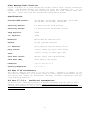
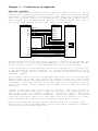
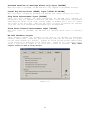
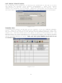
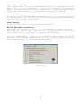
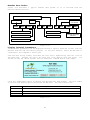
WX-1000
Digital Weather Receiver
Computer Automation Technology, Inc
4631 N.W. 31st Avenue, Suite 142
Fort Lauderdale, Florida 33309
Phone: (954) 978-6171 Fax: (561) 488-2894
Internet: http://www.catauto.com
Table of Contents
Chapter
Page
1.
Introduction and Specifications
1-1
2.
Interfacing to Repeater
2-1
3.
Configuration Programming
3-1
4.
Drawings
4-1
5.
Schematics
5-1
6.
Parts List
6-1
REVISED
04/02/02
(V2.01)
2
Chapter 1 - Introduction and Specifications
WX-1000 Weather Receiver
The WX-1000 is a highly sensitive, quality receiver, with good front-end protection
designed to function in the high RF environment typical of many repeater sites. A
digital decoder responds to Specific Area Message Encoded (SAME) alerts transmitted
by the NOAA weather station located in your geographic area. Select your county code
and the type of alert. Select warnings and or watches.
During a weather alert, a
relay in the WX-1000 will disconnect the transmitter from the controller and connect
it to the weather receiver.
The relay provides a ground for the transmitter PTT
line. Weather audio will be transmitted for the period of the alert announcement. A
programmable alert timer provides back-up protection.
Weather Alert Log
As alerts are received the WX-1000 stores the date, time and type of alert in nonvolatile memory. Storage space is provided for forty alerts. Use the RS-232 port
and the WX-1000 configuration program to down load the data. A print driver is also
provided.
Front Panel Controls And Displays
Two toggle switches control weather receiver operation. The MONITOR switch activates
the speaker. The VOLUME control includes the power switch and adjusts the speaker
output level. The red ALERT LED flashes when an alert is received. This LED will
continue to flash until the alert period has expired or the spring loaded RESET
switch is pressed. The RESET switch has two functions during an active alert.
A
short activation then release will voice the present alert.
A long activation
(longer than one second) then release will cancel an alert. NOTE: The MONITOR switch
must be down to receive weather alerts.
Alert Start Logic Output (J3-7)
An ALERT START output provides a TTL logic high two second pulse when a weather alert
is received.
This output can be used to set off an external alarm or trigger the
controller to execute a macro or load a “SEVERE WEATHER ALERT” memory save.
Alert Stop Logic Output (J3-6)
Included in the digital packet is the length of the severe weather alert. The WX1000 stores this information and generates a stop logic output when the time period
has expired. An ALERT STOP output provides a TTL logic high for one second. This
output can be used to trigger the controller to reload the “NORMAL” memory save.
Weather Enable Input (J3-9)
When this input is grounded the weather receiver will activate. When connected to a
controller's user function output switch, weather reports on demand are available.
Weather Disable Input (J3-4)
When this input is grounded the WX-1000 will not respond to weather alerts issued by
the NOAA weather station. Once a “Sky Warn Net” is activated, it may be desirable to
stop any additional alerts.
Weather Reset Input (J3-12)
Momentary grounding this input will reset the WX-1000 receiver terminating the alert
and message. Note: From the “WX-1000 Hardware Inputs Outputs” window dot the circle
to select “Cancel any activate alerts.”
3
Alert Message Timer Selection
At the conclusion of an alert message the weather station send a digital termination
packet.
The WX-1000 decodes this packet and turns the transmitter off.
If the
weather station fails to send the termination packet the alert message timer will
take over. Select this time with the WX-1000 configuration program.
Specifications
Available NOAA Channels:
162.400 MHz, 162.425 MHz, 162.450 MHz, 162.475 MHz
162.500 MHz, 162.525 MHz, 162.550 MHz
Sensitivity Receive:
0.5 microvolts for 20 dB quieting
Sensitivity Decoder:
1.0 microvolts for 95% decoder accuracy
Image Rejection:
-55dB
I.F. Rejection:
-60dB
Modulation:
Narrow Band FM, 5KHz Deviation
Antenna:
50 Ohm, Type BNC Connector
L.O. Emissions:
Fully complaint with FCC Rules, Part 15
Relay Closure:
2 Form C (DPDT) by Digital Alert Packet
Power:
+12VDC @ 120 ma, DC Power Type 2.5mm
Front Panel Control:
Monitor, Reset, Power ON-OFF/Volume
Front Panel LEDs:
Green (Power), Red (Alarm)
Dimensions:
3.5" H x 19" W x 7" D
Operating Temperature:
-15 to +55 C
FCC Part 15 RF Interference
This device complies with part 15 of the FCC Rules.
Operation is subject to the
following two conditions: (1) This device may not cause harmful interference, and (2)
this device must accept any interference received, including interference that may
cause undesired operation.
FCC Part 97.113.e
Prohibited transmissions.
No station shall retransmit programs or signals emanating from any type of radio
station other than an amateur station, except propagation and weather forecast
information intended for use by the general public and originated from United States
Government stations.
4
Chapter 2 - Interfacing to Repeater
CAT-1000 Interface
Connect the WX-1000 to the CAT-1000 and the repeater as shown in Figure 2-1. PTT and
transmit audio from the CAT-1000 are connected to the repeater's transmitter through
the normally closed contacts of the double pole double throw relay located in the WX1000. Set the power switch to on, the WX-1000 will announce the firmware version.
When a weather alert is received, the relay will switch the weather alert audio to
the TX audio input and provide a PTT signal to key the transmitter.
REPEATER
CAT-1000
J4-13
J4-6
J4-4
J4-25
J4-10
J4-11
RX AUDIO
WX-1000
RX AUDIO
COR
COR
CTCSS
CTCSS
GROUND
GROUND
PTT
PTT
TX AUDIO
TX AUDIO
GROUND
PTT GROUND
TX AUDIO OUTPUT
PTT OUTPUT
PTT INPUT
TX AUDIO INPUT
J1-5
J1-6
J1-7
J1-1
J1-10
J1-22
OUTPUT #1
WX ENABLE INPUT
OUTPUT #2
WX DISABLE INPUT
WX INPUT #1 (RESET)
OUTPUT #3
INPUT #1
WX ALERT START OUTPUT
INPUT #2
WX ALERT STOP OUTPUT
GROUND
GROUND
J3-1
J3-11
J3-3
J3-2
J3-10
J3-9
J3-4
J3-12
J3-7
J3-6
J3-8
Figure 2-1
The WX-1000 receiver can be activated at anytime, by turning on the CAT-1000 user
function output #1 which grounds the WX ENABLE pin (J3-9) on the WX-1000 receiver.
Key-up and enter: [100811]. To stop the broadcast key-up and enter: [100810].
It may be desirable to stop additional alerts when a skywarn net is activated. Turn
on the CAT-1000 user function output #2. This grounds the WX DISABLE pin (J3-4) on
the WX-1000. Key-up and enter: [100821]. To activate the weather receiver, key-up
and enter: [100820].
When a weather alert is received, the WX ALERT START OUTPUT (J3-7) will provide a two
second positive DC voltage [TTL] level to the CAT-1000 at INPUT #1.
Program this
input to load a memory save pre-programmed for “several weather” conditions. Follow
the example: Unlock the controller and program INPUT #1 to load memory save #4 by
entering [*171 5204]. Control operator Zone 7 Channel 1 must be enabled for INPUT #1
to function.
Included in the alert packet is the length of the alert.
When the alert time has
expired, the WX ALERT STOP OUTPUT (J3-6) will provide a one second positive DC
voltage [TTL] level to the CAT-1000 at INPUT #2. Program this input to load a memory
save pre-programmed for “normal” conditions.
Follow the example:
Unlock the
controller and program INPUT #2 to load memory save #1 by entering [*171 5201].
Control operator Zone 7 Channel 2 must be enabled for INPUT #2 to function.
NOTE: Do not operate the CAT-1000 repeater controller with Zone 7 channels 1 and 2
enabled unless you have programmed memory file #1 with “normal” conditions and memory
file #4 with “severe” weather conditions.
5
The weather
noon. Check
test message
memory file
scheduler to
noon.
bureau usually tests the system every Wednesday between 11 AM and 12
with your local weather service office for the exact day and time. The
will be transmitted on your repeater. However you may not want to load
#4 when its just a test.
To prevent the memory file load use the
disable hardware input #1 at 11AM and enable hardware input #1 at 12
Program scheduler position #1 at 11:00 AM on Wednesday to turn off Zone 7 Channel #1.
Unlock the controller.
Key-up and enter:
[*1101 11 00 4 00 00 1710]. Program
scheduler position #2 at 12:00 NOON on Wednesday to turn on Zone 7 Channel #1. Keyup and enter: [*1102 12 00 4 00 00 1711].
Dual Port Repeater Controller Interface (Alternate)
If the WX-1000 is connected to a dual port repeater controller, such as the CAT-1000,
CAT-700, CAT-300DXL or the CAT-200, and the second port is not being used, the WX1000 can be connected as a remote base receiver.
Connect the WX-1000, CAT-1000 and the repeater as shown in Figure 2-2. The WX-1000
transmit audio output becomes the RX Audio #2 of the CAT-1000.
The WX-1000 PTT
Output becomes the COR #2 input of the CAT-1000. Note: COR #2 is active LOW. Install
a 2200-ohm pull-up resistor on the CAT-1000 board at R75 and set dip switch #2 to ON.
Key-up and enter the remote base command [5001] to enable port #2.
CAT-1000
PORT #1
REPEATER
RX AUDIO #1
13
COR #1
6
CTCSS #1
4
GROUND
25
PTT #1
10
TX AUDIO #1
11
24
PORT #2
WX-1000
RX AUDIO
COR
CTCSS
GROUND
PTT
TX AUDIO
1
GROUND
RX AUDIO #2
PTT GROUND
8 GROUND
11 TX AUDIO OUTPUT
12
COR #2
5
3
Figure 2-2
6
PTT OUTPUT
CAT-300DX Interface
Connect the WX-1000 to the CAT-300DX and the repeater as shown in Figure 2-3.
REPEATER
CAT-300DX
J3-13
J3-6
J3-4
J3-25
J3-10
J3-11
RX AUDIO
WX-1000
RX AUDIO
COR
COR
CTCSS
CTCSS
GROUND
GROUND
PTT
PTT
TX AUDIO
TX AUDIO
GROUND
PTT GROUND
TX AUDIO OUTPUT
PTT OUTPUT
PTT INPUT
TX AUDIO INPUT
J3-7
J3-8
J3-9
J3-1
J3-2
J3-22
OUTPUT #1
WX ENABLE INPUT
OUTPUT #2
OUTPUT #3
WX DISABLE INPUT
WX INPUT #1 (RESET)
INPUT #1
INPUT #2
WX ALERT START OUTPUT
WX ALERT STOP OUTPUT
GROUND
GROUND
J3-1
J3-11
J3-3
J3-2
J3-10
J3-9
J3-4
J3-12
J3-7
J3-6
J3-8
Figure 2-3
The WX-1000 receiver can be activated at anytime, by turning on the CAT-300DX user
function output #1 which grounds the WX ENABLE pin on the WX-1000 receiver. Key-up
and enter: [100661]. To stop the weather broadcast key-up and enter: [100660].
CAT-700 Interface
Connect the WX-1000 to the CAT-700 and the repeater as shown in Figure 2-4.
REPEATER
CAT-700
J4-13
J4-6
J4-4
J4-24
RX AUDIO
RX AUDIO
COR
CTCSS
COR
CTCSS
GROUND
GROUND
PTT
J4-10
TX AUDIO
J4-11
PTT
TX AUDIO
GROUND
PTT GROUND
TX AUDIO OUTPUT
PTT OUTPUT
PTT INPUT
J4-14
TX AUDIO INPUT
WX ENABLE INPUT
OUTPUT #1
OUTPUT #2
J4-15
OUTPUT #3
J4-19
INPUT #1
J4-1
INPUT #2
J4-2
GROUND
J4-18
WX-1000
WX DISABLE INPUT
WX INPUT #1 (RESET)
WX ALERT START OUTPUT
WX ALERT STOP OUTPUT
GROUND
J3-1
J3-11
J3-3
J3-2
J3-10
J3-9
J3-4
J3-12
J3-7
J3-6
J3-8
Figure 2-4
The WX-1000 receiver can be activated at anytime, by turning on the CAT-700 user
function output #1 which grounds the WX ENABLE pin on the WX-1000 receiver. Key-up
and enter: [100551]. To stop the weather broadcast key-up and enter: [100550].
7
CAT-200 Interface
Connect the WX-1000 to the CAT-200 and the repeater as shown in Figure 2-5.
REPEATER
CAT-200
J3-13
J3-6
J3-4
J3-25
RX AUDIO
WX-1000
RX AUDIO
COR
COR
CTCSS
GROUND
PTT
CTCSS
GROUND
J3-10
TX AUDIO
J3-11
PTT
TX AUDIO
GROUND
PTT GROUND
TX AUDIO OUTPUT
PTT OUTPUT
PTT INPUT
J4-14
TX AUDIO INPUT
WX ENABLE INPUT
OUTPUT #1
WX DISABLE INPUT
WX INPUT #1 (RESET)
OUTPUT #2
J4-15
OUTPUT #3
J4-19
J4-18
GROUND
GROUND
J3-1
J3-11
J3-3
J3-2
J3-10
J3-9
J3-4
J3-12
J3-8
Figure 2-5
The WX-1000 receiver can be activated at anytime, by turning on the CAT-200 user
function output #1 which grounds the WX ENABLE pin on the WX-1000 receiver. Key-up
and enter: [100351]. To stop the weather broadcast key-up and enter: [100350].
CAT-300DXL Interface
Connect the WX-1000 to the CAT-300DXL and the repeater as shown in Figure 2-6.
REPEATER
CAT-300DXL
J3-13
J3-6
J3-4
J3-25
J3-10
J3-11
RX AUDIO
WX-1000
RX AUDIO
COR
COR
CTCSS
CTCSS
GROUND
GROUND
PTT
PTT
TX AUDIO
TX AUDIO
GROUND
PTT GROUND
TX AUDIO OUTPUT
PTT OUTPUT
PTT INPUT
TX AUDIO INPUT
J3-14
J3-15
J3-19
J3-1
J3-2
J3-24
OUTPUT #1
WX ENABLE INPUT
OUTPUT #2
WX DISABLE INPUT
WX INPUT #1 (RESET)
OUTPUT #3
INPUT #1
INPUT #2
WX ALERT START OUTPUT
WX ALERT STOP OUTPUT
GROUND
GROUND
J3-1
J3-11
J3-3
J3-2
J3-10
J3-9
J3-4
J3-12
J3-7
J3-6
J3-8
Figure 2-6
The WX-1000 receiver can be activated at anytime, by turning on the CAT-300DXL user
function output #1 which grounds the WX ENABLE pin on the WX-1000 receiver. Key-up
and enter: [100751]. To stop the weather broadcast key-up and enter: [100750].
Computer Interface J1
Connect your computer’s serial port to the WX-1000 receiver at connector J1.
Use
Radio Shack shielded RS-232 cable (cat No. 26-117B) or equivalent. This cable is a
DB-9 male to DB-9 female with pins 2-2 and 3-3.
8
12VDC Interface J2
Connect a 12VDC power supply to the WX-1000 receiver through the 2.5mm power jack J2.
The center pin is positive. In stand-by mode the WX-1000 requires approximately 100
ma.
Repeater Interface PTT Ground [J3-1]
Connect this pin to the transmitter chassis ground. This will insure that during an
alert the PTT line will be returned to transmitter chassis ground.
Repeater Interface PTT Input [J3-2]
Connect this pin to the controller PTT output.
Repeater Interface PTT Output [J3-3]
Connect this pin to the transmitter PTT input.
Repeater Interface Weather Alert Disable Input [J3-4]
Connect this pin to a user function switch on the controller.
When this input is
grounded, the receiver will not respond to alerts issued by the weather station.
Repeater Interface Weather Output #2 [J3-5]
From the “WX-1000 Hardware Inputs and Outputs” window select a one second pulse
output “With All Decoded Events”, “With Watch or Warning Decoded Events”, “With Watch
Decoded Events”, “With Warning Decoded Events” or “With Non Watch or Warning Decoded
Events”.
Repeater Interface Weather Alert Stop Output [J3-6]
When a weather alert is received, embedded in the digital message is the length of
the alert. When this time period has expired, this output will go active high (TTL)
for one second. Connect this pin to a logic input on the controller. Program the
controller to load the NORMAL memory file.
Repeater Interface Weather Alert Start Output [J3-7]
When a weather alert is received, this output goes active high (TTL) for two seconds.
Connect this pin to a logic input on the controller. Program the controller to load
a SEVERE WEATHER memory file.
Repeater Interface Ground [J3-8]
Connect this pin to controller ground.
controller and WX-1000 receiver.
This provides a common ground between the
Repeater Interface Weather Alert Enable Input [J3-9]
Connect this input to a user function switch on the controller.
grounded, the weather receiver will activate.
When this input is
Repeater Interface TX Audio Input [J3-10]
Connect this input to the controller transmit audio output.
Repeater Interface TX Audio Output [J3-11]
Connect this output to the repeater transmit audio input.
Repeater Interface Weather Input #1 [J3-12]
Connect this input to a user function switch on the controller. When this input is
momentarily grounded the WX-1000 will reset. Note: From the “WX-1000 Hardware Inputs
Outputs” window dot the circle to select “Cancel any activate alerts.”
9
Repeater Interface Weather Output #3 [J3-13]
From the “WX-1000 Hardware Inputs and Outputs” window, select the Output #3 tab.
From the list of “Rising Edge” events dot the circle of the event you wish to cause
output #3 to rise to +5 volts. From the trailing edge list dot the circle of the
event you wish to cause output #3 to drop back to 0 volts.
Repeater Interface Weather Output #1 [J3-14]
From the “WX-1000 Hardware Inputs and Outputs” window select a one second pulse
output “With All Decoded Events”, “With Watch or Warning Decoded Events”, “With Watch
Decoded Events”, “With Warning Decoded Events” or “With Non Watch or Warning Decoded
Events”.
Repeater Interface Weather Input #2 [J3-15]
After the alert message is sent, the WX-1000 will periodically key the transmitter
and send a voice synthesizer announcement. Set the J5 jumper on pins 2 and 3. This
connects input #2 to the PTT input. When the PTT input is active low, meaning the
repeater is in use, the voice synthesizer announcement will be suppressed. Note: From
the “WX-1000 Hardware Inputs Outputs” window dot the circle to select “Skip voice
announcements”.
Antenna Interface J4
Connect an antenna to the BNC connector J4. If the WX-1000 is located in the fringe
area of the NOAA transmitter an external antenna is recommended. Do not locate the
antenna near any transmitting antennas.
WX-1000 Frequency Adjustments
The WX-1000 is shipped with its frequency set to 162.550 MHz. To change to a
different NOAA frequency, change the settings of dipswitch SW1.
SW1-1
SW1-2
SW1-3
FREQUENCY
OFF
OFF
OFF
162.400 MHz
ON
OFF
OFF
162.425 MHz
OFF
ON
OFF
162.450 MHz
ON
ON
OFF
162.475 MHz
OFF
OFF
ON
162.500 MHz
ON
OFF
ON
162.525 MHz
OFF
ON
ON
162.550 MHz
Figure 2-6
WX-1000 Audio Adjustments
Transmit audio from the controller has a direct connection to the transmitter through
the WX-1000.
There is no need to readjust transmitter deviation.
Set the MONITOR
switch on the front panel to on.
Monitor the transmitter output. Adjust the LINE
LEVEL audio control R25 for the desired level of weather station audio.
With the
MONITOR switch on, activate the RESET switch.
The voice synthesizer will announce the selected FIP codes and voice the station ID if
activated. Continue to cycle the RESET switch as required until the LINE VOICE LEVEL
audio control R24 is adjusted for the desired Voice synthesizer level. The SPEAKER
VOICE LEVEL audio control R23 has been factory set and should not require any
additional adjustments.
10
Play Test Packets
You
can
generate
test
packets
with
your
computer’s sound card to test the WX-1000. NOTE:
Insure that during the test sequence the sound
card is not configured to apply “special effects”
to the sound files.
Connect the output of the sound card to the
modulation input of a RF signal generator. Set
the frequency to 162.XXX MHz at 3KHz deviation.
If a signal generator is not available connect a
cable from the output of the sound card to WX1000 at TP2.
This is the junction of R9 (10K)
and C34 (.015uF).
Figure 2-7
Reset the WX-1000 to the default values.
Set the MONITOR switch to ON.
Hold the
spring loaded RESET switch up and turn on the WX-1000 receiver. Check that the RED
ALERT LED flashes.
Start the WX-1000 program, click on the “HELP” menu and select “Play Test Packets”.
Insure that the MONITOR switch is down and click on one of the TEST buttons to
activate the test sequence.
TEST
PREDEFINED DATE
PREDEFINED LENGTH
Required Weekly Test
July 31
15 Minutes
Flash Flood Warning
July 31
1 Hour
Severe Thunderstorm Watch
July 31
1 Hour
Tornado Watch
July 31
1 Hour
Figure 2-8
Each packet contains the following 10 FIP codes:
012099-012011-012025-000000-000000-000000-000000-000000-000000-012999
NOTE:
codes.
After completion of the test remember to upload your local parameters and
11
Chapter 3 - Configuration Programming
The WX-1000 Configuration program requires a Windows 95, 98, 2000, NT or Me operating
system. Install the program. Press START, PROGRAMS, and WX1000 Weather Receiver to
display the [WX-1000 DIGITAL WEATHER RECEIVER] window.
Figure 3-1
WX-1000 Setup
Click the [Program Setup] button to display the [WX-1000 SETUP] window. Select your
computer’s serial port or click on the “Serial Port Test” button. Your computer will
determine which port is connected to the WX-1000. The time of the alert is sent in
the digital packet as GMT time. Select your time zone so the configuration program
can calculate your local time.
Check the box to automatically adjust for daylight
savings time. Click [OK].
Figure 3-2
12
Federal Information Processing Codes
From the WX-1000 Digital Weather Receiver window click the [U.S. FLAG] button to
display the [WX-1000 FIPS Codes] window. Click the [SELECT STATE / TRANSMITTER CITY]
button to display the [WX-1000 STATE / TRANSMITTER LOCATION] window.
Figure 3-3
WX-1000 State / Transmitter Entry
Select the state and frequency from the drop down boxes. Select the transmitter
location and Click [OK].
Figure 3-4
13
The WX-1000 FIPS Codes window will display the counties serviced by the selected
transmitter. Select the desired county or counties by checking the boxes along the
left column. Up to 24 counties can be selected. When the selections are complete,
click [OK] to return to the WX-1000 FIPS Code window.
Figure 3-5
FIPS Code Editor
The WX-1000 editor program includes an all states database derived from the database
of the NOAA weather service at www.noaa.org.
As changes are made by the weather
service the all states data file for the WX-1000 editor is up-dated and available on
the computer automation web site at www.catauto.com. The WX-1000 FIPS Editor window
permits the addition of codes that do not appear on the current published lists. See
Figure 3-6.
Figure 3-6
14
WX-1000 Event Codes
Click the [STORM CLOUD] button to display the [WX-1000 EVENT CODES] Window. Select up
to twenty-four events by checking the box next to each event. When the selections are
complete check OK.
WX-1000 Options Settings
Figure 3-7
Click the [TOOLS] button to display the [WX-1000 OPTIONS SELECT] Window.
Options
include Received Alert Options, Front Panel Switch Options, Override Options and Voice
Interval Options. Select the desired options and click [OK].
Figure 3-8
15
Received Alert Options
These boxes should be checked to activate the front panel speaker, transmitter and
front panel LED.
Front Panel Switch Options
These boxes should be checked for the front panel MONITOR switch to activate the
speaker, transmitter and line audio.
Override Options
If the accept all FIP and Event Codes boxes are checked, the WX-1000 will respond to
all alerts issued by the weather station.
Operation is similar to a receiver with
1050Hz decoder only.
Voice Interval Options
When the alert message is finished the weather station sends a termination
packet. Upon recipe of this packet the WX-1000 will turn off the speaker, line
and repeater transmitter. The voice synthesizer will continue to announce the
until the time period has expired. Select the desired voice alert options and
OK.
data
audio
alert
click
WX-1000 Timer Settings
Click the [CLOCK] button to display the [WX-1000 TIMER SELECT] Window.
Timers
include: Speaker Time-out, Line Time-out, Pre Voice Delay Timer, Voice Interval Timer
and Relay Activation Delay Timer. Select the desired times and click [OK].
Speaker Time-out Option
Figure 3-9
This timer selects the time the front panel speaker is enabled when an alert message
is sent by the weather station. A termination data packet is sent at the end of the
alert message to disable the speaker.
Should the weather station fail to send the
termination data packet this timer will disable the front panel speaker.
Line Time-out Option
This timer selects the time the line audio and PTT outputs are active when an alert
message is sent by the weather station. A termination data packet is sent at the end
of the alert message. Should the weather station fail to send the termination data
packet this timer will limit the alert transmission time.
16
Pre Voice Delay
This timer selects the delay between activation of the control relay and when the
voice synthesizer begins to speak.
Voice Interval Timer Option
Imbedded in the alert information packet is the time the warning or watch is in
effect. The time is sent in fifteen-minute increments for the first hour and thirty
minute increments for the remaining time of the alert.
Once the alert message is
finished, the red alert led on the front panel will continue to flash and the WX-1000
voice synthesizer will periodically key-up the repeater transmitter and announce the
nature of the alert.
This timer sets the time between voice synthesizer
announcements.
Relay Activation Delay
When the digital packet is decoded the relay disconnects the transmitter from the
controller.
If you want to use the features of your repeater’s controller to send
paging tones, alert tones or a custom voice message announcement this disconnect must
be delayed. Use this feature to select the delay.
WX-1000 Hardware Inputs
Click the [CONNECTOR] button to display the [WX-1000 HARDWARE INPUTS AND OUTPUTS]
window. Two hardware inputs are provided on the back of the WX-1000 for additional
control. Two tab selection dialog boxes can be selected to program how the two inputs
will control the WX-1000.
Figure 3-10
Activate Receiver On All Alerts Input [GROUND]
When this input is grounded, the WX-1000 will respond to all alerts issued by the
weather station regardless of the event codes programmed into its memory.
Activate Receiver On Watches and Warnings Only Input [GROUND]
When this input is grounded, the WX-1000 will only respond to programmed watches and
warnings.
17
Activate Receiver On Warnings Alerts Only Input [GROUND]
When this input is grounded, the WX-1000 will only respond to programmed warnings.
Cancel Any Active Alert (RESET) Input [PULSE TO GROUND]
When this input is momentary grounded, the WX-1000 will reset, canceling the alert.
Skip Voice Announcement Input [GROUND]
After the alert message has been transmitted the WX-1000 will
periodically key the repeater transmitter and send a voice synthesizer
describing the nature of the alert. Connect jumper J5 between pins 2 and
this input to the PTT input. When the PTT input is active low meaning
is in use, the voice synthesizer announcement will be suppressed.
continue to
announcement
3 to connect
the repeater
Force Voice Interval Announcement Input [GROUND]
When this input is grounded, the WX-1000 will announce which event is currently
active.
WX-1000 Hardware Outputs
Three hardware outputs are provided on the back of the WX-1000 for additional
external controlling.
Three tab selection dialog boxes can be selected to program
how the three outputs will operate. Outputs #1 and #2 provide pulsed outputs based
on the selection as indicated on the dialog box. Output #3 is a TTL level control
giving a high and low output of (+5 Volts and 0 Volts) as selected.
Note: These
outputs cannot be used as relay drivers.
Figure 3-11
18
Call Letter Identification
Use the WX-1000 voice synthesizer to identify the transmitter at the end of an alert
and during the periodic voice weather announcements.
Enter your station
identification in the Call Letter Box.
Valid characters are A-Z and 0-9.
Up to
fifteen (15) characters can be entered. Additional check boxes are provided to add
the words “This is”, “Transmitter” and “Repeater” to the identification announcement.
Transfer Data
Figure 3-12
To transfer data between the WX-1000 and your computer, click the [COMPUTER TRANSFER]
button. After the current configuration up loads the alert history will down load.
The alert history will display in the [WX-1000 DIGITAL WEATHER RECEIVER] window. See
Figure 3-13. The most recent alert will appear in group #1 table position #1. The
WX-1000 memory will store information on the last forty alerts. The display includes
the Date, Time and Event Code description. Warnings are displayed in red, watches in
yellow, and test messages in white. NOTE: The front panel MONITOR switch must be off
to transfer data.
Figure 3-13
19
Test County FIP Codes
After a data transfer, set the front panel MONITOR switch to on and momentary flip the
RESET switch.
The voice synthesizer will read out the county FIP codes stored in
memory.
Example: The voice will say:
“WX1000 TEST FIP CODES ARE 013067 013089
013121.” The voice synthesizer will also announce the station ID if enabled.
Reset WX-1000 Memory
Turn off the receiver, set the front panel MONITOR switch to on, hold the reset switch
up while turning the power on. When the RED alert LED flashes the WX-1000 memory has
been reset and filled with default values.
Print History
To print the alert history, click the [PRINT HISTORY] button.
WX-1000 Raw Data Transmission
The WX-1000 will send the raw data as it was received from the weather service as a
ASCII string at 4800-baud 8N1.
This data may be imported directly into an alpha
numeric paging system or interfaced to a computer based alarm system.
To activate this feature click the [COMPUTER TERMINAL] button to display the [RS-232
Rear Port Options] Window.
Check the box to send the weather packet out the rear
RS232 port. Select the desired options and click [OK]. Check the Append boxes to add
special ASCII characters to the raw data dump as necessary.
Figure 3-14
20
Weather Data Packet
Figure 3-15 describes a typical weather data packet as it is received from the
National Weather Service.
LENGTH OF ALERT 6 HOURS 30 MINUTES
SYNCHRONIZER
ZCZC
ALERT DATE 281 DAY OF THE YEAR
ALERT TIME
9:33 AM GMT
FLORIDA
WXR
FFW
0
12
011
0630
281
0933
NATIONAL WEATHER SERVICE
CALL LETTERS (MIAMI)
FLASH FLOOD WARNING
BROWARD COUNTY
WMIA
NWS
NATIONAL WEATHER
SERVICE
ALL SECTIONS OF THE COUNTY
Display Internal Parameters
Figure 3-15
Internal data parameters can be displayed through a special download of data from the
WX-1000 receiver and this editor program. To use this feature, insure the WX-1000 is
connected to the computer’s serial port.
From the main dialog window, hold down the left “Ctrl” keyboard key and left click on
the menu help. Release the “Ctrl” key then left click “About” with your mouse. You
should now see the “about window” with an additional command button “Data Dump”.
Figure 3-16
Click the “DUMP DATA” button to display the WX-1000 Data Dump window. Use this window
to receive and display special data from the WX-1000. The four buttons are:
NV Data
Dumps the non-volatile memory data.
RAW Data
Dumps the last raw data as received from the alert transmission.
Clear
Clears out the window.
Save Window
When activated, displayed data will be saved to a file.
Figure 3-17
21
Click the “RAW DATA” button to display the last alert received by the WX-1000.
Figure 3-18
Event Codes
EAN
EAT
NIC
NPT
RMT
RWT
ADR
ADM
BRT
BZW
CEM
DMO
EVI
FFA
FFW
FFS
FLA
FLW
Emergency Action Notification
Emergency Action Termination
National Information Center
National Periodic Test
Required Monthly Test
Required Weekly Test
Administrative Message
System Test
Special Broadcast
Blizzard Warning
Civil Emergency Message
Practice / Demo Warning
Evacuate Immediate
Flash Flood Watch
Flash Flood Warning
Flash Flood Statement
Flood Watch
Flood Warning
FLS
HWA
HWW
HUW
HLS
LFP
NPW
SVA
SVR
SPS
SVW
TOA
TOR
TOS
TOW
WSA
TSA
TSW
22
Flood Statement
High Wind Watch
Hurricane Watch
Hurricane Warning
Hurricane Statement
Local Public Forecast
Wind Chill Advisory
Severe Thunderstorm Watch
Severe Thunderstorm Statement
Special Weather Statement
Severe Thunderstorm Warning
Tornado Watch
Tornado Warning (OLD)
Tornado Statement
Tornado Warning
Winter Storm Warning
Tsunami Watch
Tsunami Warning
Chapter 4 - Drawings
Figure 4-1
23
Chapter 5 - Schematics
WX-1000 Schematic
Sheet 1
of
3
WX-1000 Schematic
Sheet 2
of
3
WX-1000 Schematic
Sheet 3
of
3
24
Chapter 6 - Part List
1
1
1
1
1
1
11
Bead Inductor
Cap Diode
Capacitor
Capacitor
Capacitor
Capacitor
Capacitor
P9810
6.8pf
.0015uf
.0047uf
.0082uf
.027uf Film Cap
.1uf 50V
1
7
2
6
4
3
1
14
Capacitor
Capacitor
Capacitor
Capacitor
Capacitor
Capacitor
Capacitor
Capacitor
4.7uf 16V
10uf 16V
470uf 25V
.001uf
.01uf
.015uf
.033uf
.1uf
2
1
1
4
1
1
7
2
2
1
1
1
1
1
1
1
1
5
1
2
1
1
1
2
2
1
1
1
1
1
1
1
1
1
1
Capacitor
Capacitor
Capacitor
Capacitor
Capacitor
Capacitor
Capacitor
Capacitor
Capacitor
Capacitor
Capacitor
Connector
Connector
Connector
Crystal
Crystal
Crystal
Diode
Diode
Filter
Filter
Fuse
Header
Header
I.C.
I.C.
I.C.
I.C.
I.C.
I.C.
I.C.
I.C.
I.C.
I.C.
I.C.
SM
SM
SM
SM
SM
SM
SM
SM
SM
SM
SM
SM
SM
SM
SM
Var
0.5pf
5.6pf
8.2pf
10pf
15pf
22pf
33pf
47pf
120pf
470pf
.7-20pf
9D (F)
15D (F)
DC Power
3.27MHz
10.245 MHz
16MHz
1N4148
1.5KE20A
10.7 MHz
455 KHz
0.5 Amp
1X2
1X3
25C320
74HC14
74HC157
74HC4053
78L05
LM340-T5.0
LM340-T8
LM348M
LM386
LM1458M
MAR-1SM
L3
VR1
C27
C17
C21
C22
C8,C10,C11,C16,C18,C19,
C20,C25,C28,C38,C39
C23
C4,C5,C6,C9,C29,C31,C37
C7,C26
C32,C33,C51,C72,C73,C75
C48,C55,C58,C63
C30,C34,C35
C64
C36,C40,C41,C42,C43,C50,
C52,C53,C61,C65,C74,C76,
C79,C80
C47,C57
C68
C67
C46,C54,C59,C69
C45
C70
C1,C2,C13,C14,C56,C66,C77
C44,C62
C60,C78
C49
C71
J1
J3
J2
Y1
Y3
Y4
CR4,CR5,CR6,CR7,CR8
CR14
FL1,FL2
FL3
F1
J4
J5,J8
U6,Y2
U5
U9
U14
U16
U8
U17
U13
U12
U4
U18
25
1
1
1
1
1
1
1
1
1
1
1
1
1
1
1
2
1
1
2
3
1
1
1
2
1
1
1
1
1
1
1
1
1
3
5
2
1
1
2
3
5
1
1
1
1
1
1
5
1
1
I.C.
I.C.
I.C.
I.C.
I.C.
I.C.
I.C.
I.C.
I.C.
Inductor
JFET
LED
LED
Pot with Switch
Relay
Resistor
Resistor
Resistor
Resistor
Resistor
Resistor
Resistor
Resistor
Resistor
Resistor
Resistor
Resistor
Resistor
Resistor
Resistor SM
Resistor SM
Resistor SM
Resistor SM
Resistor SM
Resistor SM
Resistor SM
Resistor SM
Resistor SM
Resistor SM
Resistor SM
Resistor SM
Resistor SM
Resistor SM
Switch
Switch
Switch
Test Point
Transformer
Transformer
Transistor
MC13135
MC145170-2
MCP101
NJM78L09UA
P89C51RD2
TC232CPE
TPIC6C595
TSP53C30AN2L
XR2211
100uh
MMBFU310
Alert (Red)
Power (Green)
10K Audio Taper
12V DPDT
1.0K
4.7K Network 10P
10 Ohm
10K SIP
10K Var
20.5K 1%
33K
68K
100
100K
470K
510K
620
SIP 6
1K
1.8K
3.9K
4.7K
6.8K
10K
18K
22K
33K
68K
100
100K
270
470K
4 Position Dip
DPDT Toggle
SPST Alert Reset
.065uh
Quad Coil
FET NE25118
U15
U19
U3
U20
U7
U2
U10
U1
U11
L1
Q5
DS1
DS2
R52
K1
R27,R48
R1
R26
R29,R30
R23,R24,R25
R7
R28
R2
R13,R14
R3
R6
R5
R12
R8
R40
R41
R34
R39
R20,R53,R54
R9,R19,R22,R36,R42
R15,R16
R18
R17
R35,R43
R32,R33,R47
R21,R44,R46,R50,R51
R49
R45
SW1
S2
S1
TP1
T3,T4,T5,T6,T7
T2
Q3
26