1
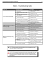
Authorized Technician
TECHNICAL MAINTENANCE MANUAL
CALYPSO/TITAN/OCTOPUS
SECOND STAGE
2
Contents
COPYRIGHT NOTICE...............................................................................................................................................3
INTRODUCTION .......................................................................................................................................................3
WARNINGS, CAUTIONS, & NOTES.........................................................................................................................3
SCHEDULED SERVICE............................................................................................................................................3
GENERAL GUIDELINES ..........................................................................................................................................3
GENERAL CONVENTIONS......................................................................................................................................4
DISASSEMBLY PROCEDURES...............................................................................................................................4
REASSEMBLY PROCEDURES................................................................................................................................7
FINAL TESTING......................................................................................................................................................11
Second Stage Airflow Test................................................................................................................................................................. 11
Second Stage Opening Effort Test.................................................................................................................................................... 11
Second Stage Purge Flow Test ......................................................................................................................................................... 11
External Leak Test .............................................................................................................................................................................. 11
Subjective Breathing Test.................................................................................................................................................................. 12
TABLE 1 - SECOND-STAGE TROUBLESHOOTING GUIDE.................................................................................13
TABLE 2 - RECOMMENDED TOOL LIST ..............................................................................................................14
TABLE 3 - STANDARD PARTS REPLACEMENT SCHEDULE .............................................................................14
TABLE 4 - RECOMMENDED LUBRICANTS AND CLEANERS...........................................................................15
PROCEDURE A - CLEANING AND LUBRICATION..............................................................................................16
TABLE 5 -TORQUE SPECIFICATIONS..................................................................................................................17
TABLE 6 - TEST BENCH SPECIFICATIONS .........................................................................................................17
EXPLODED PARTS DIAGRAM ..............................................................................................................................19
3
Calypso/Titan Second Stage Service Manual
COPYRIGHT NOTICE
This manual is copyrighted, all rights reserved. It may not, in
whole or in part, be copied, photocopied, reproduced, translated,
or reduced to any electronic medium or machine readable form
without prior consent in writing from Aqua Lung America. It may
not be distributed through the internet or computer bulletin board
systems without prior consent in writing from Aqua Lung America.
©2004 Aqua Lung America, Inc.
Calypso/Titan Second Stage Repair Manual
INTRODUCTION
This manual provides factory prescribed procedures for the correct service and repair of the Aqua Lung Calypso/Titan secondstage regulator. It is not intended to be used as an instructional
manual for untrained personnel. The procedures outlined within
this manual are to be performed only by personnel who have received factory authorized training through an Aqua Lung Service
& Repair Seminar. If you do not completely understand all of the
procedures outlined in this manual, contact Aqua Lung to speak
directly with a Technical Advisor before proceeding any further.
2.
Checking for stable intermediate pressure that is within the
acceptable range.
3.
Checking for opening effort that is within the acceptable
range.
4.
Checking for smooth operation of the control knob and
venturi switch.
5.
A visual inspection of the filter for debris or discoloration.
6.
A visual inspection of the exhaust valve to see that it is in
good shape and that it’s resting against a clean surface.
7.
A visual inspection of the mouthpiece looking for tears or
holes.
8.
Pulling back hose protectors and checking that the hoses
are secure in the hose crimps.
If a regulator fails item #1,2,3 or 4 the entire regulator should
be overhauled. If a regulator fails 4,5,6 or 7 it will be up to the
technician’s discretion whether or not a full overhaul is required.
GENERAL GUIDELINES
1.
In order to correctly perform the procedures outlined in this
manual, it is important to follow each step exactly in the order given. Read over the entire manual to become familiar
with all procedures before attempting to disassemble the
first-stage, and to learn which specialty tools and replacement parts will be required. Keep the manual open beside
you for reference while performing each procedure. Do not
rely on memory.
2.
All service and repair should be carried out in a work area
specifically set up and equipped for the task. Adequate
lighting, cleanliness, and easy access to all required tools
are essential for an efficient repair facility.
3.
As the regulator is disassembled, reusable components
should be segregated and not allowed to intermix with
nonreusable parts or parts from other units. Delicate parts,
including inlet fittings and crowns which contain critical
sealing surfaces, must be protected and isolated from other
parts to prevent damage during the cleaning procedure.
Use only genuine Aqua Lung parts provided in the Calypso/
Titan second-stage overhaul parts kit (p/n 900010). DO
NOT attempt to substitute an Aqua Lung part with another
manufacturer’s, regardless of any similarity in shape or size.
Do not attempt to reuse mandatory replacement parts
under any circumstances, regardless of the amount of use
the product has received since it was manufactured or last
serviced.
When reassembling, it is important to follow every torque
specification prescribed in this manual, using a calibrated
torque wrench. Most parts are made of either marine brass
or plastic, and can be permanently damaged by undue
stress.
In order to make the regulator compatible with nitrox up to
40%O2 (EAN40), the regulator must be properly cleaned,
lubricated and assembled using genuine Aqua Lung or
Apeks replacement parts. In addition, assembly must be
carried out in a clean environment using powderless, latex
gloves or equivalent. For more detailed information, be sure
to read Procedure A, Cleaning and Lubrication.
WARNINGS, CAUTIONS, & NOTES
Pay special attention to information provided in warnings, cautions, and notes that are accompanied by one of these symbols:
WARNINGS indicate a procedure or situation that
may result in serious injury or death if instructions
are not followed correctly.
CAUTIONS indicate any situation or technique
that will result in potential damage to the product, or render the product unsafe if instructions
are not followed correctly.
NOTES are used to emphasize important points, tips, and
reminders.
SCHEDULED SERVICE
4.
If the regulator is subjected to less than 50 dives per year, it is
permissible to overhaul it every other year with an inspection
procedure being performed on the “off” years. For example:
5.
Year #1: Inspection
Year #2: Overhaul
Year #3: Inspection
Year #4: Overhaul
and so on.
Both Inspections and Overhauls need to be documented in the
Annual Service & Inspection Record in the back of the Owner’s
Manual to keep the Limited Lifetime Warranty in effect.
If a regulator is subjected to more than 50 dives per year, it
should receive the complete overhaul.
An Official Inspection consists of:
1.
A pressurized immersion test of the entire unit to check for
air leakage.
6.
7.
4
GENERAL CONVENTIONS
1.
While holding the inlet
fitting (13) of the second
stage secure with a ¾”
(19mm) open end wrench,
apply 11/16” (17mm) openend wrench to the female
fitting of the LP hose (25).
Turn the fitting counterclockwise to loosen and
remove the hose from the
second stage. Remove the
O-rings (24&27) from the
hose and discard. Set the
hose aside.
2.
Slide back the hose protector (26) and check that
the crimps look good and
that the hose is not pulling
out. If the hose is torn or is
pulling out of the crimps, it
should be replaced.
3.
To remove the mouthpiece clamp (5), simply lift the lever
on the cam latch with a screwdriver or thumbnail. Pull the
mouthpiece (6) off. Inspect the mouthpiece to ensure it is
free of any tears or cuts that may cause leakage of water
into the second stage or other discomfort. Discard the
mouthpiece or set it aside to be reused, depending on its
condition.
Unless otherwise instructed, the following terminology and techniques are assumed:
1.
When instructed to remove, unscrew, or loosen a threaded
part, turn the part counterclockwise.
2.
When instructed to install, screw in, or tighten a threaded
part, turn the part clockwise.
3.
When instructed to remove an o-ring, use the pinch method
(see figure) if possible, or use a brass or plastic o-ring
removal tool. Avoid using hardened steel picks, as they may
damage the o-ring sealing surface. All o-rings that are removed are discarded and replaced with brand new o-rings.
Pinch Method
Press upwards on sides
of o-ring to create a
protrusion. Grab o-ring
or insert o-ring tool at
protrusion.
4.
The following acronyms are used throughout the manual:
MP is Medium Pressure; HP is High Pressure; LP is Low
Pressure.
5.
Numbers in parentheses reference the key numbers on the
exploded parts schematics. For example, in the statement,
“...remove the o-ring (8) from the venturi switch (9)...”, the
number 8 is the key number to the venturi switch o-ring.
DISASSEMBLY PROCEDURES
NOTE: Before performing any disassembly, refer to the
exploded parts drawing, which references all mandatory
replacement parts. These parts should be replaced with
new, and must not be reused under any circumstances
- regardless of the age of the regulator or how much use it
has received since it was last serviced.
CAUTION: Use only a plastic or brass o-ring
removal tool (p/n 944022) when removing o-rings
to prevent damage to the sealing surface. Even
a small scratch across an o-ring sealing surface
could result in leakage. Once an o-ring sealing
surface has been damaged, the part must be
replaced with new. DO NOT use a dental pick, or
any other steel instrument.
5
Calypso/Titan Second Stage Service Manual
4.
5.
While holding the second stage secure, firmly grasp the
collar of the front cover (1) which is seated over the venturi
control switch (9), opposite of the inlet side. Stretch the collar over the venturi control switch, and lift the front cover off
the box bottom (4) until the opposite collar can be removed
from the inlet fitting (13). Closely examine the front cover to
check for any tears, distortion, deterioration, or other signs
of damage. Replace it if found, or set it aside if it is in reusable condition.
Lift out the sealing ring
(2) and diaphragm (3)
from the box bottom,
and closely inspect the
diaphragm to ensure that
it is perfectly round and
free of any tears, deterioration, or other damage. If
deterioration or damage
is found, discard the
diaphragm and do not
attempt to reuse.
6.
Once the front cover (1) has been removed, the release
latch for the exhaust valve cover (11) becomes exposed.
Using your finger, lift the release latch and swing the exhaust valve cover off of the lugs on the box bottom (4).
7.
Inspect the exhaust valve
and its seating surface
underneath. The valve
should be clean and
supple. It should be free of
any tears, holes or defects
of any kind. It should have
well defined edges. If it is
dirty or compromised in
any way, it must get replaced. The seated surface underneath the valve must be clean.
8.
Using your finger, reach
into the box bottom (4)
and remove the retaining clip (7) for the venturi
switch.
9.
Grasp the venturi switch
(9) between your thumb
and forefinger and pull
it straight out of the box
bottom (4).
10.
Remove and discard the
O-ring (8) from the venturi
switch (9), and closely examine the O-ring groove
of the venturi switch to
check for any nicks or
scratches. Discard if
found, or set it aside if it
is in reusable condition.
11.
While holding the box bottom (4) secure, apply a 3/4”
(19mm) open end wrench to the inlet fitting (13). While
depressing the lever (18), carefully turn the fitting counterclockwise to loosen and remove. Remove and discard the
o-ring (12).
12.
Apply a medium blade
screwdriver to the slotted
head of the crown (14)
inside the inlet fitting (13),
and hold the inlet fitting
secure while turning the
crown counter-clockwise to
disengage the threads.
6
NOTE: Because the crown is o-ring sealed, it will not
freely exit the valve body after it has been disengaged.
The following step must be performed correctly in order to
remove the crown without damaging its delicate sealing
surface.
13.
14.
15.
16.
Stand the valve assembly vertical on the head of the poppet
(22), with the lever (18) facing up, and depress the valve
body (19) to expose the locknut (16). While holding the
valve body fully depressed, apply a 1/4” nut driver to turn
the locknut counter-clockwise until it has disengaged from
the threads of the poppet. Remove the locknut, washer
(17), and lever, and slowly relax the valve body (19) to lift it
off the poppet and spring (21). Discard the locknut, and do
not attempt to reuse.
17.
Closely inspect the shape and condition of the lever (18) to
ensure it is not bent, corroded, or otherwise damaged. If
any signs of damage or corrosion are found, discard the
lever and do not reuse.
18.
Closely examine the poppet spring (21) with a magnifier to
ensure it is not damaged (bent) or corroded. If any signs of
damage or corrosion are found, discard the spring and do
not reuse.
19.
Using a needle or sharp
pick, stick the center of
the LP seat (23) inside the
head of the poppet (22)
and lift the seat out, being
very careful to avoid damaging the poppet. Set the
seat aside to be used as
an aid during reassembly,
and inspect the head of
the poppet to check for any nicks, scratches, or other signs
of damage. The through-hole beneath the LP seat cavity
should be clear and free of any obstructions. If any signs of
damage are found, discard the poppet and do not attempt
to reuse.
When the crown (14) has been unthreaded from the inlet
fitting (13), carefully insert the pin of the extraction tool (P/N
109437) into the opposite end of the inlet fitting and through
the center of the crown. Gently press the crown out onto a
padded surface (see Fig. 1). Remove and discard the crown
o-ring (15).
Closely examine the crown (14) with the use of magnifier to check for any scoring, nicks, or other damage to the
polished sealing surface. If damage is found, discard the
crown, and do not attempt to reuse. If it is in reusable condition, set it aside on a soft surface to prevent damage to the
sealing edge.
Press the valve body (19)
with lever assembly into
the box bottom (4) by
inserting a finger through
the inlet opening. Gently
lift the assembly out of the
box bottom, being careful
to avoid pulling or tugging
on the lever (18).
WARNING: The components that make up the
valve subassembly are under spring tension. Disassemble according to instructions found in the
next step. Failure to wear proper eye protection
could result in an eye injury should the components (16-23) eject out of the valve body (19).
NOTE: The used LP seat is an essential aid to the reassembly procedure for the valve body. Do not discard the
seat until the reassembly and final adjustment procedures
have both been performed, and the regulator is functioning
satisfactorily.
7
Calypso/Titan Second Stage Service Manual
20.
Place the handle of the extraction tool directly over the
poppet bearing (20) in the top center of the valve body (19),
and press downward until the poppet bearing has dropped
out. Discard the poppet bearing, and do not reuse.
REASSEMBLY PROCEDURES
NOTE: Before performing any reassembly, it is important
to inspect all parts, both new and those that are being reused, to ensure that every part and component is perfectly
clean and free of any dust, corrosion, or blemishes. Check
all o-rings to ensure they are clean and supple before
dressing with Christo-Lube® MCG-111.
1.
If you removed the exhaust
valve (10) during disassembly, install the exhaust
valve into the box bottom
(4) by feeding the stem of
the exhaust valve into the
center hole of the valve in
the box bottom. Gently pull
the stem through the hole
on the opposite side inside
the box bottom, until the barb has passed through and is
securely seated against the opposite side. If you are installing a new valve, carefully snip off the excess material of the
stem with a small pair of scissors, leaving 5mm.
2.
Install the o-ring (12) on
the inlet fitting (13), securing it into the groove at the
base of the threads, just
above the hex feature.
3.
Install the o-ring (15) onto
the crown (14), and carefully insert the threaded
end of the crown into the
hose connection of the
inlet fitting (13). Gently
press it in further with the
blunt end of the extraction
tool (P/N 109437) until it
stops (see Fig. 2).
NOTE: Aqua Lung no longer requires mandatory replacement of the exhaust valves. As long as the valves and their
associated seating surfaces are clean and in good condition, they may be left in place.
This Ends Disassembly
Before starting reassembly, perform parts
cleaning and lubrication according to the
procedures outlined in Procedure A, titled
Cleaning & Lubrication, on page 16.
Fig. 2 - Crown Installation
8
4.
Using tool p/n 125727, engage the slotted head of the
crown (14) and drive it in clockwise as far as the tool will
allow. If the tool is not available, use a medium flathead
screwdriver to drive the crown in as far as it will go and then
back it out 3 revolutions.
5.
Stand the inlet fitting (13)
vertical on a flat surface
with the sealing edge of
the crown (14) facing up
inside. Lay the previously
used LP seat (23) inside
the inlet fitting, over
the sealing edge of the
crown.
8.
Stand the poppet (22) on
its head inside the top of
the inlet fitting (13) and
on top of the old LP seat.
Place the spring (21) over
the poppet shaft.
9.
Hold the inlet fitting (13)
secure, and mate the valve
body (19) with poppet
bearing down over the
poppet shaft (22). Press
the valve body downward
to compress the spring
while turning it clockwise
to engage the threads of
the inlet fitting, and then
continue turning it slowly
until the threaded portion
of the poppet shaft stands
outside the poppet bearing
(20).
NOTE: It is essential to use a spare LP seat in order to
prevent damage to the new seat while performing the following steps of the reassembly procedure.
6.
Place the poppet bearing (20) over the pin of the extraction tool with the square feature facing up. Guide the pin
of the tool into the open end of the valve body (19) and out
through the square hole in its center. While sighting through
the top of the valve body, rotate the tool as needed to align
the square feature of the poppet bearing with the square
hole, and press the tool upward to seat the bearing securely
in place. When finished, check to ensure that the top of the
poppet bearing is flush with the top of the valve body.
CAUTION: If resistance is felt, immediately stop
and unscrew the valve body from the inlet fitting
to check the alignment of the poppet shaft and
poppet bearing. Excessive force and misalignment will otherwise result in damage to the poppet bearing, requiring its replacement.
10.
7.
Press the new LP seat (23)
into the cavity in the head
of the poppet (22), with the
smooth side facing out.
Lay the arms of the lever
(18) inside the groove
of the valve body (19),
straddling the poppet
shaft (22), so that the
curved portion of the
lever faces away from the
air outlet hole.
9
Calypso/Titan Second Stage Service Manual
11.
12.
13.
Place the washer (17)
over the poppet shaft
(22), followed by the
locknut (16), with the flat
side facing down. Being
careful to avoid disturbing
the lever (18), turn the
locknut clockwise by hand
to engage the threads
of the poppet, and then
apply a 1/4” nut driver to
turn it further; only until 1
thread of the poppet shaft
is visible above the top of
the locknut.
Hold the valve body (19)
with lever (18) stationary and upright with
one hand, and slowly
unscrew the inlet fitting
(13) counter-clockwise to
loosen and remove from
beneath it, while watching
to ensure that the lever
rises slightly as the poppet shaft extends from
the valve body. Remove
and discard the previously used LP seat from
the inlet fitting.
Insert the valve and lever
assembly (16-23) into the
left side of the box bottom
(4) as you face it.
14.
While holding the valve assembly (16-23) securely inside
the box bottom (4) and the lever (18) depressed, mate the
shorter threaded end of the inlet fitting (13) through the
inlet port and into the valve assembly (16-23). Turn the inlet
fitting clockwise by hand until finger snug, and then apply a
torque wrench with a ¾” (19mm) crow foot to tighten it to a
torque measurement of 45 (±5) inch-pounds.
15.
Install new o-rings (24&27) on either end of the M.P. hose.
Thread the male fitting of the MP hose into the medium
pressure port of the first stage and apply a torque wrench
with a 9/16” crows foot to tighten to 40 (±2) in/lbs. Be certain
that the first stage of the regulator is functioning properly
and is delivering a medium pressure of 135 – 140 psi.
16.
Attach the female fitting of the second stage medium pressure hose to the inlet fitting (13) of the second stage. Turn
the swivel nut clockwise until finger snug.
CAUTION: Prior to adjusting and testing the
Calypso/Titan second stage regulator, the accompanying first stage must be correctly serviced, adjusted to a stable intermediate pressure
of 135-140 psi, and fully tested. Refer to the
appropriate first stage service manual before attempting to perform the adjustment and testing
of the Calypso/Titan second stage.
10
Lever Height Adjustment
17.
Pressurize the regulator
18.
Slide the notch of the adjusting tool 125727 across
the top of the box bottom
(4) The top of the lever
(18) should touch the tool
without causing a leak. At
this point, the lever should
be 2.5 mm above the rim
of the box bottom.
19.
22.
Install the venturi assembly into the right side of
the box bottom (4). Lock
it in place by inserting
the retaining clip (7). You
should hear it “click” as it
locks into place.
23.
Install the exhaust valve cover (11) by positioning the two
square holes in the cover over the mating two lugs on the
box bottom (4). Swing it up into position and engage the
latch. You should hear it “click” as it locks into place.
24.
Fit the washer (2) on to the front of the diaphragm (3) and
place the assembly into the box bottom (4).
If the notch in the tool
depresses the lever
causing a leak, in other
words, if the lever is
too high, unscrew the
locknut (16) with the ¼”
nut driver to lower the
lever (18) to the correct
height.
If the lever does not touch the tool, in other words, the lever
is too low, screw the locknut back in until the lever reaches
the correct height.
20.
Once the lever height has been set, turn off the air supply
and purge the regulator. Remove the hose (25).
21.
Install the o-ring on to the
venturi switch (9).
25. Fit the front cover (1) on to the box bottom (4) starting with
hose side. Visually inspect the cover to ensure that it is
seating evenly all the way around.
11
Calypso/Titan Second Stage Service Manual
Make sure that the cover is seated evenly all the way around
FINAL TESTING PROCEDURES
Second Stage Air Flow Test
1.
Connect the first stage regulator to a calibrated test bench
and pressurize the system to 3000 (±100) psi.
2.
Place the second stage mouthpiece over the mouthpiece
adapter. Slowly turn the flowmeter control knob until
the flow reaches a minimum of 14 SCFM (400 liters per
minute). The reading on the Magnahelic gauge (inhalation
/ exhalation effort gauge) should indicate no more than
+6.O” H2O. If the reading exceeds +6.0” H2O, refer to Table
1 - Troubleshooting for corrective guidelines and specific
procedures.
NOTE: If your facility is equipped with a test bench,
perform the tests before installing the mouthpiece. General
instructions for performing bench tests are located in the
next section, “Final Testing.”
26.
If equipped with a
Comfo-bite mouthpiece,
make sure the ‘bridge’
of the mouthpiece (6) is
facing upward. Stretch
the mouthpiece over the
second-stage mouthpiece boss. At the base
of the mouthpiece is a
groove for the reusable
clamp (5). Wrap the clamp around the mouthpiece so that
the cam buckle points toward the hose and the cam lever
points downward. Mate the cam lever hook with the hook
on the free end of the clamp. Press down on the cam lever
until the buckle snaps closed.
Second Stage Opening Effort Test
1.
Turn the flowmeter control knob shut, and then slowly
reopen while watching both the Magnahelic gauge and the
intermediate pressure gauge.
2.
When the intermediate pressure gauge begins to drop
below the intermediate pressure “lockup,” the Magnahelic
gauge should indicate an opening effort of +0.8 to +1.4 inch
of H2O for a primary second stage and +1.2 to +1.8 inch of
H2O for the octopus. If the opening effort is not within this
range, refer to Table 1 - Troubleshooting.
Second Stage Purge Flow Test
27.
Attach the MP hose (25)
to the second stage.
Using an 11/16” (17mm)
crow’s foot, apply a
torque of 40 (± 3) in. lbs.
1.
Turn off the flowmeter control knob. Next, while the second
stage is still mounted on the mouthpiece adapter, watch
the flowmeter gauge and depress the purge button until
the second stage valve is completely open. The flowmeter
gauge must indicate a minimum of +12 SCFM. If the purge
flow is less than +12 SCFM, refer to Table 1 - Troubleshooting.
2.
When purge flow is correct, remove the second-stage from
the mouthpiece adapter on the flow test bench. Shut the
valve of the test bench, and purge the second stage to
depressurize the system. Remove the regulator.
NOTE: Before performing the following procedure, refer
to Table 5, titled Test Bench Specifications – Calypso 2nd
Stage.
NOTE: If an accurately calibrated airflow test bench is not
available, proceed to the Subjective Tuning Procedures
provided on the following page.
This ends reassembly of the
Calypso/Titan Second Stage
External Leak Test
1.
After disconnecting the regulator from the flow bench, connect it to a scuba cylinder filled to approximately 3,000 psi.
Open the cylinder valve to pressurize the regulator, and
submerge the entire system in a test tank of clean water.
12
2.
Observe any bubbles
arising from the submerged regulator over a
one minute period. The
recommended time is
necessary due to slower
bubble formation that
occurs in smaller leaks.
Bubbles indicate a leak,
which requires that the
system must be disassembled at the source to check sealing surfaces, assembly sequence and component positioning in order to correct the problem(s).
NOTE: Extremely small leaks may be better detected
by applying a soap solution or Snoop™ to the leak area.
Bubble streams will indicate the source of the leak. Before
disassembling to correct any leaks, rinse the entire regulator thoroughly with fresh water and blow out all residual
moisture with filtered, low-pressure (50 psi) air. Disassemble and remedy the problem, referring to Table 1 - Troubleshooting.
Subjective Breathing Test
1.
Depress the purge cover fully to ensure that an adequate
volume of air needed to clear the second stage flows
through the mouthpiece. Then, inhale slowly but deeply
from the mouthpiece. A properly serviced and adjusted
regulator should deliver air upon deep inhalation without
excessive inhalation effort, freeflow, or “fluttering” of the
second-stage diaphragm. When exhaling, there should be
no fluttering or sticking of the exhalation valve. If any of
these problems occur, refer to Table 1 - Troubleshooting.
This concludes annual service procedures
for the Calypso/Titan Second Stage.
13
Calypso/Titan Second Stage Service Manual
Table 1 - Troubleshooting Guide
SYMPTOM
Leak or freeflow at 2nd Stage
Insufficient purge flow or work of
breathing too high
Water leak in 2nd stage during
inhalation
POSSIBLE CAUSE
TREATMENT
1. MP too high
1. Refer to First Stage Troubleshooitng Guide
2. The LP seat (23) is worn or damaged
2. Replace the LP seat
3. The crown orifice (23) is not correctly adjusted
3. Readjust the crown orifice
4. The lever (18) is bent
4. Replace the lever
5. The crown orifice (14) is damaged
5. Replace crown orifice
6. The lever (18) adjustment is too high
6. Unscrew the locknut (16)
1. MP too low
1. Refer to First Stage Troubleshooitng Guide
2. The lever (18) adjustment is too low
2. Readjust the lever and the valve
3. MP hose (25) obstructed
3. Clean or replace the hose
4. The lever (18) is bent
4. Replace the lever
1. Hole in mouthpiece (6)
1. Replace the mouthpiece
2. Diaphragm (3) is damaged
2. Replace the diaphragm
3. Exhalation valve (10) damaged
3. Replace the valve
4. The diaphragm (3) is not correctly
fitted between the casing (4) and the
washer (2)
4. Disassemble the cover and refit the
assembly correctly
5. The casing (4) is damaged
5. Check the sealing face of the exhalation valve. Replace the casing.
6. The o-ring (8) is damaged
6. Replace the o-ring
NOTE: This is a partial list of possible problems and recommended treatments. For
more information, contact Aqua Lung’s Technical Services Department for assistance with problems not described here.
CAUTION: Recommended treatments which require disassembly of the regulator must be performed during a complete overhaul, according to the prescribed procedures for scheduled, annual service. Do not attempt to perform
partial service.
14
Table 2 - Recommended Tool List
PART NO.
DESCRIPTION
APPLICATION
111610
I.P. test gauge
Intermediate pressure testing
944022
O-ring tools
O-ring removal and installation
109437
Seat extraction/installation tool
Crown removal and installation
125727
Crown/Lever Adjusting Tool
Adjusting crown (14) and lever (18)
n/a
0-120 inch/lbs torque wrench
Inlet and hose fittings installation
n/a
Magnifier with illumination
Sealing surface inspection
n/a
Ultrasonic cleaner
Brass and stainless steel parts cleaning
n/a
Medium blade screwdriver
Crown removal and installation
n/a
11/16” (17mm) wrench and crow foot
IP hose fitting
n/a
1/4” nut driver
Valve disassembly/assembly/adjustment
n/a
3/4” (19mm) wrench and crow foot
Inlet fitting
Table 3 - Standard Parts Replacement Schedule
PART NO.
DESCRIPTION
KEY NUMBER
QTY
102510
Locknut
6
1
104134
Poppet Bearing
20
1
106738
LP Seat
23
1
820011
O-ring
27
1
820010
O-ring
15,24
2
820015
O-ring
8,12
2
15
Calypso/Titan Second Stage Service Manual
Table 4 - Recommended Lubricants & Cleaners
LUBRICANT / CLEANER
®
Christo-Lube MCG-111
APPLICATION
All O-rings seals
SOURCE
Aqua Lung, PN 820466, or
Lubrication Technologies
310 Morton Street
Jackson, OH 45640
(800) 477-8704
CAUTION: Silicone rubber requires no lubrication or preservative treatment.
DO NOT apply grease or spray to silicone rubber parts. Doing so may cause a
chemical breakdown and premature deterioration of the material.
Oakite #31
Acid bath for reusable stainless
steel and brass parts.
Oakite Products, Inc.
50 Valley Road
Berkeley Heights, NJ 07922
White distilled vinegar
Acid bath for reusable stainless
steel and brass parts.
“Household” grade
CAUTION: Do not use muriatic acid for the cleaning of any parts. Even if
strongly diluted, muriatic acid can harm chrome plating and may leave a residue that is harmful to O-ring seals and other parts.
Liquid dishwashing detergent
(diluted with warm water)
Degreaser for brass and stainless
steel parts; general cleaning solution for plastic and rubber
“Household” grade
16
Procedure A
Cleaning & Lubrication
Aqua Lung and Apeks Regulators and Nitrox
When it comes to issues of nitrox safety and compatibility, the concerns lie primarily with the regulator’s first stage as it is subjected
to high inlet pressures. High inlet pressures lead to adiabatic compression or heating of the gas. The Aqua Lung or Apeks regulator
product described in this manual, when properly cleaned and assembled, is authorized for use with enriched air nitrox (EAN) that does
not exceed 40% (EAN 40). It is authorized because it has undergone adiabatic compression testing and the authorized service kit
components and lubricants are compatible in elevated oxygen environments. During cleaning, a mild detergent must be used to remove
condensed hydrocarbons (compressor oils) from the inside passageways of the first stage. For the first stage to remain EAN40 compatible, only use hyperfiltered compressed gas ( hydrocarbons < 0.1 mg/m3). Ordinary compressed breathing air (Grade E) usually does
not meet this criterion. Once ordinary breathing air is used, the first stage is no longer EAN40 compatible until it is cleaned and serviced
again.
Although regulator second stage components are not exposed to high pressure EAN, Aqua Lung and Apeks recommend that the same
cleaning procedures be followed for the complete regulator. This prevents the possibility of cross contamination and guarantees the
cleanliness of the entire regulator.
Cleaning Brass and Stainless Steel Parts
1.
Preclean in warm, soapy water* using a nylon bristle tooth brush.
2.
Thoroughly clean parts in an ultrasonic cleaner filled with soapy water. If there are stubborn deposits, household white distilled
vinegar (acetic acid) in an ultrasonic cleaner will work well. DO NOT place plastic, rubber, silicone or anodized aluminum parts in
vinegar.
3.
Remove parts from the ultrasonic cleaner and rinse with fresh water. If tap water is extremely “hard,” place the parts in a bath of
distilled water to prevent any mineral residue. Agitate lightly, and allow to soak for 5-10 minutes. Remove and blow dry with low
pressure (25 psi) filtered air, and inspect closely to ensure proper cleaning and like-new condition.
Cleaning Anodized Aluminum, Plastic & Rubber Parts
Anodized aluminum parts and parts made of plastic or rubber, such as box bottoms, box tops, dust caps, etc., may be soaked and
cleaned in a solution of warm water mixed with mild dish soap. Use only a soft nylon toothbrush to scrub away any deposits. Rinse in
fresh water and thoroughly blow dry, using low pressure filtered air.
CAUTION: Do not place plastic and rubber parts in acid solutions. Doing so may alter the physical properties of the component, causing it to prematurely degrade and/or break.
Cleaning Hoses
1.
Hose fittings: Ultrasonically clean with soapy water; vinegar OK on tough corrosion
2.
Run soapy water through hose if needed
3.
Thoroughly rinse with fresh water
4.
Blow out hose before installing
Lubrication and Dressing
Wear powderless, latex gloves when handling and lubricating o-rings. Keeping internal parts free from skin oils and other contaminates
is important when running enriched air nitrox through a first stage. All o-rings should be lubricated with Christo-Lube® MCG-111. Dress
the o-rings with a very light film of grease, and remove any visible excess by running the o-ring between thumb and forefinger. Avoid
applying excessive amounts of Christo-Lube grease, as this will attract particulate matter that may cause damage to the o-ring.
*Soapy water is defined as “household” grade liquid dishwashing detergent diluted in warm water.
17
Calypso/Titan Second Stage Service Manual
Table 5 - Torque Specifications
PART NUMBER
DESCRIPTION / KEY NUMBER
TORQUE
APF124563/APF124566
LP Hose Female Fitting (25)
40±3 inch-lbs
104106
Inlet Fitting (13)
45±5 inch-lbs
Table 6 - Test Bench Specifications
TEST
CONDITION
ACCEPTABLE RANGE
Leak Test
Inlet 2,500-3,000 (±100) psig
No leaks allowed
Opening Effort
Inlet 2,500-3,000 (±100) psig
Intermediate pressure 135-140 psi
Calypso/Titan: +1.0 - 1.6 in. H20
Octopus: +1.2 - 1.8 in. H20
Flow effort
Intermediate pressure 135-140 psi at
14 SCFM
+6 in. H20 (maximum)
Purge flow
Intermediate pressure 135-140 psi
12 SCFM flow rate
18
NOTES
19
Calypso/Titan Second Stage Service Manual
Titan • Calypso • Octopus (2004 - present)
Exploded Parts Diagram
25
26 24
27
1a
1b
1c
Key #
Part #
Description
n/a ---- 125740
n/a ---- 125835
n/a ---- 900010
Calypso 2nd Stage only
Titan 2nd Stage only
Service Kit
1a ----- 125732
1b ----- 125719
1c ----- 125724
2------- 124509
3------- 125705
4------- 125721
5------- 129154
6a ----- 109438
6b ----- 104138
7------- 125707
8------- 820015
9------- 125706
10 ----- 129174
11 ----- 125702
12 ----- 820015
Front cover, Titan
Front cover, Calypso
Front cover, Octopus
Diaphragm washer
Diaphragm
Box bottom
Mouthpiece clamp
Mouthpiece, Comfobite
Mouthpiece, Octopus
Retaining clip, venturi switch
O-ring
Venturi switch
Exhaust valve
Exhaust valve cover
O-ring
Key #
Part #
13 ----- 124506
14 ----- 100128
15 ----- 820010
16 ----- 102510
17 ----- 104129
18 ----- 125708
19 ----- 125709
20 ----- 104134
21 ----- 104127
22 ----- 104122
23 ----- 106738
24 ----- 820010
25 ----- APF124563
------- APF124566
26 ----- 102067
------- 102068
27 ----- 820011
Description
Inlet fitting
Crown orifice
O-ring
Locknut
Washer
Lever
Valve insert
Poppet bearing
Spring
Poppet
LP seat
O-ring
Hose, Black, 3/8” x 30”, w/ Protector
Hose, Octo, Yellow, 3/8” x 39”, w/ Protector
Hose Protector, Black
Hose Protector, Yellow
O-ring
Part numbers in BOLD ITALICS are included in the service kit.
Authorized Technician
TECHNICAL MAINTENANCE MANUAL
CALYPSO/TITAN/OCTOPUS SECOND STAGE
Aqua Lung America
2340 Cousteau Court, Vista CA 92081
Tel: 760-597-5000 / Web: www.aqualung.com