1
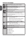
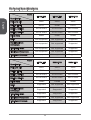
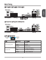
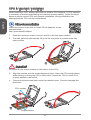
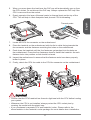
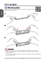
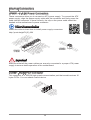
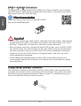
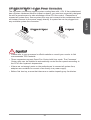
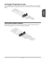
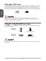
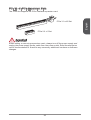
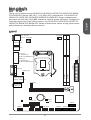
Thank you for choosing the H81M-P33/ H81M-E33/ H87M-P33/ H87M-E33/ B85MP33/ B85M-E33 Series (MS-7817 v1.X) Micro-ATX motherboard. The H81M-P33/
H81M-E33/ H87M-P33/ H87M-E33/ B85M-P33/ B85M-E33 Series motherboards
are based on Intel H81/ H87/ B85 chipset for optimal system efficiency. Designed to
fit the advanced Intel LGA1150 processor, the H81M-P33/ H81M-E33/ H87M-P33/
H87M-E33/ B85M-P33/ B85M-E33 Series motherboards deliver a high performance
and professional desktop platform solution.
Layout
CPUFAN
Top : mouse
Bottom: keyboard
USB2.0 ports
JPWR2
USB3.0 ports
SYSFAN2
DVI-D port
(for H81M-P33/
H87M-P33/ B85M-P33)
JPWR1
HDMI port
(for H81M-E33/
H87M-E33/ B85M-E33)
VGA port
Top: LAN jack
Bottom: USB ports
DIMM2
DIMM1
JUSB_PW1
SYSFAN1
T:Line-In
M:Line- Out
B:MIC-Int
PCI _E1
JBAT1
PCI _E2
JCI1
SATA2
JAUD1
JFP2
JTPM1
JCOM1
JFP1
JUSB_PW2
JUSB2
11
SATA4
JUSB1
SATA3
SATA1
English
English
Motherboard Specifications
English
CPU
Support
■ 4th Generation Intel® Core™ i7 / Core™ i5 / Core™ i3 /
Pentium® / Celeron® processors for LGA 1150 socket
Chipset
■ Intel® H81/ H87/ B85 Express Chipset
Memory
Support
■
■
■
■
Expansion
Slots
■ 1x PCIe x16 slot (optional)
■ 1x PCIe 2.0 x1 slot
Onboard
Graphics
■ 1x HDMI port (optional), supporting a maximum resolution of
2560x1600@60Hz, 24bpp/ 1920x1080@60Hz, 36bpp
■ 1x DVI-D port (optional), supporting a maximum resolution of
1920x1200 @ 60Hz, 24bpp
■ 1x VGA port, supporting a maximum resolution of 1920x1200
@ 60Hz, 24bpp
Storage
■ Intel H81/ H87/ B85 Express Chipset
- 4x SATA ports (optional)
- Supports RAID 0, RAID1, RAID 5 and RAID 10 (optional)
- Supports Intel Smart Response Technology (optional)*
- Supports Intel Rapid Start Technology (optional)*
- Supports Intel Smart Connect Technology (optional)*
* Supports Intel Core processors on Windows 7 and Windows 8
USB
■ Intel H81/ H87/ B85 Express Chipset
- 2x USB 3.0 ports on the back panel
- 8x USB 2.0 ports (4 ports on the back panel, 4 ports available through the internal USB connectors*)
Audio
■ Realtek® ALC887 Codec
LAN
■ Realtek® RTL8111G Gigabit LAN controller
Back Panel
Connectors
■
■
■
■
■
■
■
■
■
2x DDR3 memory slots supporting up to 16GB
Supports DDR3 1600/ 1333/ 1066 MHz
Dual channel memory architecture
Supports non-ECC, un-buffered memory
1x PS/2 keyboard port
1x PS/2 mouse port
4x USB 2.0 ports
2x USB 3.0 ports
1x HDMI port (optional)
1x DVI-D port (optional)
1x VGA port
1x LAN (RJ45) port
3x audio jacks
12
■
■
■
■
■
■
■
■
■
■
■
■
1x 24-pin ATX main power connector
1x 4-pin ATX 12V power connector
4x SATA connectors
2x USB 2.0 connectors (supports additional 4 USB 2.0 ports)
1x 4-pin CPU fan connector
1x 4-pin system fan connector
1x 3-pin system fan connector
1x Front panel audio connector
2x System panel connectors
1x Chassis Intrusion connector
1x Clear CMOS jumper
2x USB power jumpers
BIOS
Features
■ UEFI AMI BIOS
■ ACPI 5.0, PnP 1.0a, SM BIOS 2.7, DMI 2.0
■ Multi-language
Form Factor
■ Micro-ATX Form Factor
■ 8.9 in. x 6.8 in. (22.6 cm x 17.3 cm)
13
English
Internal
Connectors
Optional Specifications
Name
Specification
H81M-P33
H81M-E33
H87M-P33
English
PCIe x16 slot
Gen2
Gen2
Gen3
DVI-D/ HDMI
DVI-D
HDMI
DVI-D
SATA1, SATA2
SATA 6Gb/s
SATA 6Gb/s
SATA 6Gb/s
SATA3, SATA4
SATA 3Gb/s
SATA 3Gb/s
SATA 6Gb/s
64Mb
64Mb
128Mb
RAID
Not supported
Not supported
Supported
Small Business
Advantage
Not supported
Not supported
Supported
Intel Rapid Start
Not supported
Not supported
Supported
Intel Smart Response
Not supported
Not supported
Supported
Intel Smart Connect
Not supported
Not supported
Supported
H87M-E33
B85M-P33
B85M-E33
BIOS ROM
Name
Specification
PCIe x16 slot
Gen3
Gen3
Gen3
DVI-D/ HDMI
HDMI
DVI-D
HDMI
SATA1, SATA2
SATA 6Gb/s
SATA 6Gb/s
SATA 6Gb/s
SATA3, SATA4
SATA 6Gb/s
SATA 3Gb/s
SATA 3Gb/s
128Mb
128Mb
128Mb
RAID
Supported
Not supported
Not supported
Small Business
Advantage
Supported
Supported
Supported
Intel Rapid Start
Supported
Supported
Supported
Intel Smart Response
Supported
Not supported
Not supported
Intel Smart Connect
Supported
Supported
Supported
BIOS ROM
14
Back Panel
H81M-E33/ H87M-E33/ B85M-E33
Line-In
USB 2.0
VGA
Line-Out
HDMI
Mic
PS/2 Keyboard
USB 3.0
USB 2.0
H81M-P33/ H87M-P33/ B85M-P33
LAN
PS/2 Mouse
Line-In
USB 2.0
VGA
DVI-D
Line-Out
Mic
PS/2 Keyboard
USB 3.0
USB 2.0
LAN LED Indicator
LINK/ACT
LED
LED
Link/ Activity LED
Speed LED
SPEED
LED
LED Status
Description
Off
No link
Yellow
Linked
Blinking
Data activity
Off
10 Mbps connection
Green
100 Mbps connection
Orange
1 Gbps connection
15
English
LAN
PS/2 Mouse
CPU & Heatsink Installation
When installing a CPU, always remember to install a CPU heatsink. A CPU heatsink
is necessary to prevent overheating and maintain system stability. Follow the steps
below to ensure correct CPU and heatsink installation. Wrong installation can
damage both the CPU and the motherboard.
English
Video Demonstration
Watch the video to learn how to install CPU & heatsink. at the
address below.
http://youtu.be/bf5La099urI
1. Push the load lever down to unclip it and lift to the fully open position.
2. The load plate will automatically lift up as the load lever is pushed to the fully
open position.
Important
Do not touch the socket contacts or the bottom of the CPU.
3. Align the notches with the socket alignment keys. Lower the CPU straight down,
without tilting or sliding the CPU in the socket. Inspect the CPU to check if it is
properly seated in the socket.
4. Close and slide the load plate under the retention knob. Close and engage the
load lever.
CPU notches
Alignment Key
16
5. When you press down the load lever the PnP cap will automatically pop up from
the CPU socket. Do not discard the PnP cap. Always replace the PnP cap if the
CPU is removed from the socket.
Thermal paste
7. Locate the CPU fan connector on the motherboard.
8. Place the heatsink on the motherboard with the fan’s cable facing towards the
fan connector and the fasteners matching the holes on the motherboard.
9. Push down the heatsink until the four fasteners get wedged into the holes on
the motherboard. Press the four fasteners down to fasten the heatsink. As each
fastener locks into position a click should be heard.
10. Inspect the motherboard to ensure that the fastener-ends have been properly
locked in place.
11. Finally, attach the CPU fan cable to the CPU fan connector on the motherboard.
Important
• Confirm that the CPU heatsink has formed a tight seal with the CPU before booting
your system.
• Whenever the CPU is not installed, always protect the CPU socket pins by
covering the socket with the plastic cap.
• If you purchased a separate CPU and heatsink/ cooler, Please refer to the
documentation in the heatsink/ cooler package for more details about installation.
17
English
6. Evenly spread a thin layer of thermal paste (or thermal tape) on the top of the
CPU. This will help in heat dissipation and prevent CPU overheating.
Memory Installation
Video Demonstration
Watch the video to learn how to install memories at the address below.
http://youtu.be/76yLtJaKlCQ
English
1
2
3
Important
• DDR3 memory modules are not interchangeable with DDR2, and the DDR3
standard is not backward compatible. Always install DDR3 memory modules in
DDR3 DIMM slots.
• To ensure system stability, memory modules must be of the same type and density
in Dual-Channel mode.
18
Internal Connectors
These connectors allow you to connect an ATX power supply. To connect the ATX
power supply, align the power supply cable with the connector and firmly press the
cable into the connector. If done correctly, the clip on the power cable should be
hooked on the motherboard’s power connector.
Video Demonstration
Watch the video to learn how to install power supply connectors.
http://youtu.be/gkDYyR_83I4
d
n
u d
ro un
.G ro
1 .G
2
JPWR2
V
2
1 V
.+ 2
3 .+1
4
d
n
u
ro
V
.G 5 V
4
2 3.+ +5 V
d
2 . 5 s n d
2
2 1.+ Re ou un d
2 0. Gr ro un #
2 . G o Nd
9
1 8. Gr -O un
1 7. PS o
1 6. Gr V V
1 5. -12 .3
1 4. +3
1 3.
1
V
.3
3 V
.+ 2 V
2 1 2
1 1.+ +1 B OK
1 0. VS R nd
1 .5 W u
d
9 .P ro
8 .G 5V un
7 .+ ro nd
6 .G 5V u
5 + ro V
.
4 .G 3.3 3V
3 .+ 3.
2 .+
1
JPWR1
Important
Make sure that all the power cables are securely connected to a proper ATX power
supply to ensure stable operation of the motherboard.
JCOM1: Serial Port Connector
This connector is a 16550A high speed communication port that sends/receives 16
bytes FIFOs. You can attach a serial device.
in
P
o
.N S
0 T R
1 .C
8 DS R
.
6 DT N
.
4 SI
.
2
I S d
.R T n
9 . R r ou T
7 G U
.
5 . SO C D
3 .D
1
19
English
JPWR1~2: ATX Power Connectors
SATA1~4: SATA Connectors
This connector is a high-speed SATA interface port. Each connector can connect to
one SATA device. SATA devices include disk drives (HDD), solid state drives (SSD),
and optical drives (CD/ DVD/ Blu-Ray).
Video Demonstration
English
Watch the video to learn how to Install SATA HDD.
http://youtu.be/RZsMpqxythc
Important
• Many SATA devices also need a power cable from the power supply. Such devices
include disk drives (HDD), solid state drives (SSD), and optical drives (CD / DVD /
Blu-Ray). Please refer to the device’s manual for further information.
• Many computer cases also require that large SATA devices, such as HDDs, SSDs,
and optical drives, be screwed down into the case. Refer to the manual that came
with your computer case or your SATA device for further installation instructions.
• Please do not fold the SATA cable at a 90-degree angle. Data loss may result
during transmission otherwise.
• SATA cables have identical plugs on either sides of the cable. However, it is
recommended that the flat connector be connected to the motherboard for space
saving purposes.
JCI1: Chassis Intrusion Connector
This connector connects to the chassis intrusion switch cable. If the computer case
is opened, the chassis intrusion mechanism will be activated. The system will record
this intrusion and a warning message will flash on screen. To clear the warning, you
must enter the BIOS utility and clear the record.
d
n
u RU
ro T
.G IN
1 .C
2
20
The fan power connectors support system cooling fans with +12V. If the motherboard
has a System Hardware Monitor chipset on-board, you must use a specially designed
fan with a speed sensor to take advantage of the CPU fan control. Remember to
connect all system fans. Some system fans may not connect to the motherboard and
will instead connect to the power supply directly. A system fan can be plugged into
any available system fan connector.
CPUFAN/ SYSFAN1
SYSFAN2
d
n
u
ro 2V se
.G 1
1 .+ o U
2 .N
3
o
d
tr
n
n
u
ro 2V e Co
.G 1 s d
1 + en e
.
2 .S pe
3 .S
4
l
Important
• Please refer to your processor’s official website or consult your vendor to find
recommended CPU heatsink.
• These connectors support Smart Fan Control with liner mode. The Command
Center utility can be installed to automatically control the fan speeds according to
the CPU’s and system’s temperature.
• If there are not enough ports on the motherboard to connect all system fans,
adapters are available to connect a fan directly to a power supply.
• Before first boot up, ensure that there are no cables impeding any fan blades.
21
English
CPUFAN,SYSFAN1~2: Fan Power Connectors
JFP1, JFP2: System Panel Connectors
These connectors connect to the front panel switches and LEDs. The JFP1
connector is compliant with the Intel® Front Panel I/O Connectivity Design Guide.
When installing the front panel connectors, please use the optional M-Connector to
simplify installation. Plug all the wires from the computer case into the M-Connector
and then plug the M-Connector into the motherboard.
English
Video Demonstration
Watch the video to learn how to Install front panel connectors.
http://youtu.be/DPELIdVNZUI
P
o
w
e
r
0
.N
r
L
E
D
ch
it
d Sw
e
t
rv se
D
E
se e
L
e R
D
.R
D
9 .+
H
7 .
5 .3 .+
1
JFP2
5 r
C ke
C ea
r
.V p 5 e
4 S CC ak
.
3 .V pe
2 .S
1
in
P o 8.
.+
6 .4 +
.
2
e
ch
w
it
o
w
1
S
P
JFP1
Important
• On the connectors coming from the case, pins marked by small triangles are
positive wires. Please use the diagrams above and the writing on the optional MConnectors to determine correct connector orientation and placement.
• The majority of the computer case’s front panel connectors will primarily be
plugged into JFP1.
JUSB1~2: USB 2.0 Expansion Connectors
This connector is designed for connecting high-speed USB peripherals such as USB
HDDs, digital cameras, MP3 players, printers, modems, and many others.
d
C un +
.N o 1
0 r B 1 .G S B1
8
.U S
6 .U C
4 VC
.
2
in
P nd
o u +
.N r o 0
9 .G SB 07 U B
.
S
5 .U CC
3 .V
1
Important
Note that the VCC and GND pins must be connected correctly to avoid possible
damage.
22
ct
te
e
D
e
n
o
n
h
io
P
ct
d
e
a
e in et
.H P D
0 o
1 .N IC
8 M C nd
.
6 .N ou
4 Gr
.
2
io
n
L
e D
n
o N
h E R
P _S ne
d
o
a E h
e NS P
.H E d
9 .S ea R
7 H IC L
.
5 .M IC
3 .M
1
JTPM1: TPM Module Connector
This connector connects to a TPM (Trusted Platform Module). Please refer to the
TPM security platform manual for more details and usages.
3
in
p 2
ta in
a p 1
d ta pin 0
n
e s & da ta pi
m s & da ta
a
ra re s
F d s & d
C ad dre ss &
P
re s
.L C d d s
3 P a d re
1 .L C a d et
11 .LP C ad es k
9 .LP C R loc
7 .LP C C
5 .LP C
3 .LP
1
d
n
u d
r
ro un n r
e
.G ro Pi we Q r ow
4
1 2.G o Po IR e p
1 0.N V ial ow by
1 .5 er P nd
8 S 3V ta
.
6 .3. S
4 .3V
2
23
English
JAUD1: Front Panel Audio Connector
This connector allows you to connect the front audio panel located on your computer
case. This connector is compliant with the Intel® Front Panel I/O Connectivity Design
Guide.
JBAT1: Clear CMOS Jumper
There is CMOS RAM onboard that is external powered from a battery located on the
motherboard to save system configuration data. With the CMOS RAM, the system
can automatically boot into the operating system (OS) every time it is turned on. If
you want to clear the system configuration, set the jumpers to clear the CMOS RAM.
English
1
1
Keep Data
Clear Data
Important
You can clear the CMOS RAM by shorting this jumper while the system is off.
Afterwards, open the jumper . Do not clear the CMOS RAM while the system is on
because it will damage the motherboard.
JUSB_PW1, JUSB_PW2: USB Power Jumper
This jumper allows you to enable/ disable the “Wakeup from S3/S4/S5 by USB and
PS/2 device” function.
JUSB_PW1
1
1
JUSB_PW2
Enabled
Disabled (Default)
Enabled
Disabled (Default)
1
1
Important
If you set the jumper to Enabled, the power supply must be able to provide at least
2A currents.
24
PCI_E1~2: PCIe Expansion Slots
PCIe 3.0 x16 Slot
PCIe 2.0 x1 Slot
Important
When adding or removing expansion cards, always turn off the power supply and
unplug the power supply power cable from the power outlet. Read the expansion
card’s documentation to check for any necessary additional hardware or software
changes.
25
English
The PCIe slot supports the PCIe interface expansion card.
BIOS Setup
The default settings offer the optimal performance for system stability in normal
conditions. You may need to run the Setup program when:
English
■ An error message appears on the screen during the system booting up, and
requests you to run SETUP.
■ You want to change the default settings for customized features.
Important
• Please load the default settings to restore the optimal system performance and
stability if the system becomes unstable after changing BIOS settings. Select the
"Restore Defaults" and press <Enter> in BIOS to load the default settings.
• If you are unfamiliar with the BIOS settings, we recommend that you keep the
default settings to avoid possible system damage or failure booting due to
inappropriate BIOS configuration.
Entering BIOS Setup
Power on the computer and the system will start the Power On Self Test (POST)
process. When the message below appears on the screen, please <DEL> key to
enter BIOS:
Press DEL key to enter Setup Menu, F11 to enter Boot Menu
If the message disappears before you respond and you still need to enter BIOS,
restart the system by turning the computer OFF then back ON or pressing the
RESET button. You may also restart the system by simultaneously pressing <Ctrl>,
<Alt>, and <Delete> keys.
MSI additionally provides two methods to enter the BIOS setup. You can click the
“GO2BIOS” tab on “MSI Fast Boot” utility screen or press the physical “GO2BIOS"
button (optional) on the motherboard to enable the system going to BIOS setup
directly at next boot.
Click "GO2BIOS" tab on "MSI Fast
Boot" utility screen.
Important
Please be sure to install the “MSI Fast Boot” utility before using it to enter the BIOS
setup.
26
Overview
Model name
Virtual OC
Genie Button
System
information
Boot device
priority bar
BIOS menu
selection
BIOS menu
selection
Menu display
OC Menu
Important
• Overclocking your PC manually is only recommended for advanced users.
• Overclocking is not guaranteed, and if done improperly, can void your warranty or
severely damage your hardware.
• If you are unfamiliar with overclocking, we advise you to use OC Genie for easy
overclocking.
27
English
After entering BIOS, the following screen is displayed.
Temperature monitor
Language
▶ Current CPU/ DRAM/ Ring Frequency
These items show the current frequencies of installed CPU, Memory and Ring.
Read-only.
English
▶ CPU Ratio Mode [Auto]
Selects the CPU Ratio operating mode.
[Auto]This setting will be configured automatically by BIOS.
[Fixed Mode]Fixes the CPU ratio.
[Dynamic Mode] CPU ratio will be changed dynamically according to the CPU loading.
▶ Adjust CPU Ratio [Auto]
Sets the CPU ratio that is used to determine CPU clock speed. This item can only be
changed if the processor supports this function.
▶ Adjusted CPU Frequency
Shows the adjusted CPU frequency. Read-only.
▶ EIST [Enabled]
Enables or disables the Enhanced Intel® SpeedStep Technology.
▶ Intel Turbo Boost [Enabled]
Enables or disables the Intel® Turbo Boost. This item appears when the installed
CPU supports this function.
[Enabled] Enables this function to boost CPU performance automatically
above rated specifications when system request the highest
performance state.
[Disabled] Disables this function.
▶ Enhanced Turbo [Auto]
Enables or disables Enhanced Turbo function for all CPU cores to boost CPU
performance.
[Auto]
This setting will be configured automatically by BIOS.
[Enabled] All CPU cores would be increased to maximum turbo ratio.
[Disabled] Disables this function.
▶ Adjust Ring Ratio [Auto]
Sets the ring ratio. The valid value range depends on the installed CPU.
▶ Adjusted Ring Frequency
Shows the adjusted Ring frequency. Read-only.
▶ Adjust GT Ratio [Auto]
Sets the integrated graphics ratio. The valid value range depends on the installed
CPU.
▶ Adjusted GT Frequency
Shows the adjusted integrated graphics frequency. Read-only.
▶ DRAM Frequency [Auto]
Sets the DRAM frequency. Please note the overclocking behavior is not guaranteed.
28
▶ DRAM Timing Mode [Auto]
Selects the memory timing mode.
[Auto]
DRAM timings will be determined based on SPD (Serial Presence
Detect) of installed memory modules.
[Link]
Allows user to configure the DRAM timing manually for all memory
channel.
[UnLink]
Allows user to configure the DRAM timing manually for respective
memory channel.
▶ Advanced DRAM Configuration
Press <Enter> to enter the sub-menu. This sub-menu will be activated after setting
[Link] or [Unlink] in “DRAM Timing Mode”. User can set the memory timing for each
memory channel. The system may become unstable or unbootable after changing
memory timing. If it occurs, please clear the CMOS data and restore the default
settings. (Refer to the Clear CMOS jumper/ button section to clear the CMOS data,
and enter the BIOS to load the default settings.)
▶ Memory Fast Boot [Auto]
Enables or disables the initiation and training for memory every booting.
[Auto]
This setting will be configured automatically by BIOS.
[Enabled] Memory will completely imitate the archive of first initiation and
first training. After that, the memory will not be initialed and trained
when booting to accelerate the system booting time.
[Disabled]
The memory will be initialed and trained every booting.
▶ DRAM Voltage [Auto]
Sets the memory voltage. If set to "Auto", BIOS will set memory voltage
automatically or you can set it manually.
▶ Spread Spectrum
This function reduces the EMI (Electromagnetic Interference) generated by
modulating clock generator pulses.
[Enabled]
Enables the spread spectrum function to reduce the EMI
(Electromagnetic Interference) problem.
[Disabled]
Enhances the overclocking ability of CPU Base clock.
Important
• If you do not have any EMI problem, leave the setting at [Disabled] for optimal
system stability and performance. But if you are plagued by EMI, select the value
of Spread Spectrum for EMI reduction.
• The greater the Spread Spectrum value is, the greater the EMI is reduced, and
the system will become less stable. For the most suitable Spread Spectrum value,
please consult your local EMI regulation.
• Remember to disable Spread Spectrum if you are overclocking because even a
slight jitter can introduce a temporary boost in clock speed which may just cause
29
English
▶ Adjusted DRAM Frequency
Shows the adjusted DRAM frequency. Read-only.
your overclocked processor to lock up.
▶ CPU Features
Press <Enter> to enter the sub-menu.
English
▶ Hyper-Threading Technology [Enabled]
The processor uses Hyper-Threading technology to increase transaction rates
and reduces end-user response times. Intel Hyper-Threading technology treats
the multi cores inside the processor as multi logical processors that can execute
instructions simultaneously. In this way, the system performance is highly
improved.
[Enable]
Enables Intel Hyper-Threading technology.
[Disabled] Disables this item if the system does not support HT function.
▶ Active Processor Cores [All]
This item allows you to select the number of active processor cores.
▶ Limit CPUID Maximum [Disabled]
Enables or disables the extended CPUID value.
[Enabled]
BIOS will limit the maximum CPUID input value to circumvent
boot problems with older operating system that do not support
the processor with extended CPUID value.
[Disabled]
Use the actual maximum CPUID input value.
▶ Execute Disable Bit [Enabled]
Intel’s Execute Disable Bit functionality can prevent certain classes of malicious
“buffer overflow” attacks where worms attempt to execute code to damage the
system. It is recommended that keeps this item enabled always.
[Enabled]
Enables NO-Execution protection to prevent the malicious
attacks and worms.
[Disabled]
Disables this function.
▶ Intel Virtualization Tech [Enabled]
Enables or disables Intel Virtualization technology.
[Enabled]
Enables Intel Virtualization technology and allows a platform
to run multiple operating systems in independent partitions.
The system can function as multiple systems virtually.
[Disabled]
Disables this function.
▶ Hardware Prefetcher [Enabled]
Enables or disables the hardware prefetcher (MLC Streamer prefetcher).
[Enabled]
Allows the hardware prefetcher to automatically pre-fetch
data and instructions into L2 cache from memory for tuning
the CPU performance.
[Disabled]
Disables the hardware prefetcher.
▶ Adjacent Cache Line Prefetch [Enabled]
Enables or disables the CPU hardware prefetcher (MLC Spatial prefetcher).
[Enabled]
Enables adjacent cache line prefetching for reducing the
cache latency time and tuning the performance to the specific
application.
30
[Disabled]
Enables the requested cache line only.
▶ Intel Adaptive Thermal Monitor [Enabled]
Enables or disables the Intel adaptive thermal monitor function to protect the
CPU from overheating.
[Enabled]
Throttles down the CPU core clock speed when the CPU is
over the adaptive temperature.
[Disabled]
Disables this function.
▶ Intel C-State [Auto]
C-state is a processor power management technology defined by ACPI.
[Auto]
This setting will be configured automatically by BIOS.
[Enabled]
Detects the idle state of system and reduce CPU power
consumption accordingly.
[Disabled] Disable this function.
▶ C1E Support [Disabled]
Enables or disables the C1E function for power-saving in halt state. This item
appears when "Intel C-State" is enabled.
[Enabled]
Enables C1E function to reduce the CPU frequency and
voltage for power-saving in halt state.
[Disabled]
Disables this function.
▶ Package C State limit [Auto]
This item allows you to select a CPU C-state mode for power-saving when
system is idle. This item appears when "Intel C-State" is enabled.
[Auto]
This setting will be configured automatically by BIOS.
[C0~C7s] The power-saving level from high to low is C7s, C7, C6, C3,
C2, then C0.
[No limit]
No C-state limit for CPU.
▶ LakeTiny Feature [Disabled]
Enables or disables Intel Lake Tiny feature with iRST for SSD. This item appears
when a installed CPU supports this function and "Intel C-State" is enabled.
[Enabled]
Enhance the dynamic IO load adjusted performance for
accelerating the SSD speed.
[Disabled]
Disables this feature.
31
English
▶ CPU AES Instructions [Enabled]
Enables or disables the CPU AES (Advanced Encryption Standard-New
Instructions) support. This item appears when a CPU supports this function.
[Enabled]
Enables Intel AES support.
[Disabled]
Disables Intel AES support.
Note: The following items will appear when "Intel Turbo Boost " is enabled.
▶ Long Duration Power Limit (W) [Auto]
Sets the long duration TDP power limit for CPU in Turbo Boost mode.
▶ Long Duration Maintained (s) [Auto]
Sets the maintaining time for "Long duration power Limit(W)".
English
▶ Short Duration Power Limit (W) [Auto]
Sets the short duration TDP power limit for CPU in Turbo Boost mode.
▶ CPU Current limit (A) [Auto]
Sets maximum current limit of CPU package in Turbo Boost mode. When the
current is over the specified limit value, the CPU will automatically reduce the
core frequency for reducing the current.
▶ 1/2/3/4-Core Ratio Limit [Auto]
These items only appear when a CPU that support this function is installed.
These items allow you to set the CPU ratios for different number of active cores
in turbo boost mode. These items appear when the installed processor supports
this function.
32