1
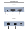
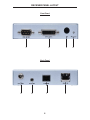
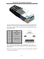
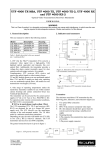
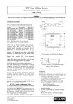
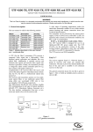
®
DVI RS-232 Over
Fiber
EXT-DVI-FO-141
User Manual
www.gefen.com
ASKING FOR ASSISTANCE
Technical Support:
Telephone
(818) 772-9100
(800) 545-6900
Fax
(818) 772-9120
Technical Support Hours:
8:00 AM to 5:00 PM Monday thru Friday PST
Write To:
Gefen Inc.
c/o Customer Service
20600 Nordhoff St
Chatsworth, CA 91311
www.gefen.com
[email protected]
Notice
Gefen Inc. reserves the right to make changes in the hardware, packaging and
any accompanying documentation without prior written notice.
DVI RS-232 over Fibertm is a trademark of Gefen Inc.
© 2010 Gefen Inc., All Rights Reserved
All trademarks are the property of their respective owners.
Rev A3
CONTENTS
1
Introduction
2
Operation Notes
3
Features
4
Sender Panel Layout
5
Sender Panel Descriptions
6
Receiver Panel Layout
7
Receiver Panel Descriptions
8
Connecting And Operating The DVI RS-232 Over Fiber
9
Network Cable Wiring Diagram
10 Specifications
11 Warranty
INTRODUCTION
Congratulations on your purchase of the DVI RS-232 over Fiber. Your complete
satisfaction is very important to us.
Gefen
Gefen delivers innovative, progressive computer and electronics add-on solutions
that harness integration, extension, distribution and conversion technologies.
Gefen’s reliable, plug-and-play products supplement cross-platform computer
systems, professional audio/video environments and HDTV systems of all sizes
with hard-working solutions that are easy to implement and simple to operate.
The Gefen DVI RS-232 over Fiber
The Gefen DVI RS232 over Fiber is a perfect solution for extending and
managing control systems, touchscreen or digital signage applications at great
distances. The DVI RS232 sends DVI, RS232, and IR signals up to 1000 feet
using a single CAT5 and single SC fiber. RS232 and IR signals are transmitted
over a single CAT5 cable while the DVI signal is transmitted over a single SC
fiber.
How It Works
The DVI RS232 over Fiber system consists of a Sender and a Receiver unit.
The Sender connects to the computer’s DVI-compliant video card output, and
RS-232 port. The DVI RS232 over fiber Receiver connects to the remote display
and RS232 and IR devices. One strand of SC fiber optic cable and a CAT5 cable
connects the Sender and Receiver together.
1
OPERATION NOTES
READ THESE NOTES BEFORE INSTALLING OR
OPERATING THE DVI RS-232 OVER FIBER
•
Use one SC terminated multi-mode fiber optic cable and one industry
standard CAT-5, CAT-5e or CAT-6 cables to operate the DVI RS-232 over
Fiber. Gefen recommends CAT-6 cabling for maximum performance.
•
For 1080p video, maximum extension is 1000 feet (330 meters).
•
IR repeater functionality is only from the receiving unit to the sending unit. IR
data cannot be transmitted from the sending unit to the receiving unit.
2
FEATURES
Features
•
Extends any DVI and RS-232 compliant device up to 1000 feet from the
computer
•
Perfect for digital signage applications
•
Video is transmitted digitally over fiber optic cable for zero signal loss
•
Supports resolutions up to 1080p, 2K, and 1920 x 1200
•
HDCP Compliant.
•
Supports DDWG standards for DVI-compliant monitors
Package Includes
(1) DVI RS232 Sender
(1) DVI RS232 Receiver
(1) 6 ft. Dual Link DVI Cable (M-M)
(1) 6 ft. RS-232 DB9 Cable (M-F)
(2) 5V DC Universal Power Supply with Locking Connector
(1) User’s Manual
3
SENDER PANEL LAYOUT
Front Panel
1
2
3
4
Back Panel
5
6
4
7
SENDER PANEL DESCRIPTIONS
1
LED Power Indicator
This LED will become active once the included 5V DC power supply is properly
connected between the sender and an open wall power socket.
2
IR Out (Blaster)
An optional IR transmitter/blaster (EXT-2IREMIT) connects to this output port.
The IR blaster’s IR emitter will need to be placed on or near the IR receiver of a
device for proper relaying of commands from the receiver.
3
DVI-D Input
This receptacle will accept a DVI Single-Link source device.
4
RS-232 Serial Communications Input
This port is capable of 2-way serial communication between RS-232 devices
connected to the sender and receiver. This port can be connected to a
computer’s serial communications port for interaction with a RS-232 serial
communications device connected to the receiver.
5
RJ-45 Link Connector
This port is used to connect the sending and receiving units together for data
traffic. Use a CAT-5, CAT-5e or CAT-6 cable. When field terminating cable
please adhere to the TIA/EIA-568-B specification (page 9).
6
Fiber Optic Connector (Multi-Mode SC Type)
This connector accepts 1 strand of SC terminated fiber optic cable that will link
the sending and receiving unit together. The DVI RS-232 over Fiber system will
only accept multi-mode fiber optic cabling.
7
Locking 5V DC Power Input
Connect the included 5V DC power supply to this input. The Power LED will
become active when the 5V DC power supply has been properly connected
to the unit and an open wall power socket. This receptacle features a locking
connector for a secure connection.
5
RECEIVER PANEL LAYOUT
Front Panel
1
2
3
Back Panel
5
6
7
6
8
4
RECEIVER PANEL DESCRIPTIONS
1
RS-232 Serial Communications Input
This port is capable of 2-way serial communication between RS-232 devices
connected to the sender and receiver. This port can be connected to a
computer’s serial communications port for interaction with a RS-232 serial
communications device connected to the receiver.
2
DVI-D Output
This receptacle will accept a DVI capable Single-Link output device.
3
Infrared (IR) Window
This sensor captures IR commands from a remote control, then relays the
IR commands from the receiving unit to the sending unit for output to a IR
transmitter (blaster) on a IR controllable device at the A/V source location.
4
LED Power Indicator
This LED will become active once the included 5V DC power supply is properly
connected between the receiver and an open wall power socket.
5
Locking 5V DC Power Input
Connect the included 5V DC power supply to this input. The Power LED will
become active when the 5V DC power supply has been properly connected
to the unit and an open wall power socket. This receptacle features a locking
connector that withstands tugs or tension on the cable, keeping the unit
powered during such events.
6
Infrared (IR) Receiver Extender Port
This port will accept the optional 6-foot IR extension cable (Gefen part# EXTRMT-EXTIR). This is useful for installations where the IR Window on the front
panel (Item 2 here) is not in line-of-sight with the IR remote control. An example
of this situation is when the Receiver is tucked away behind furniture or is
located in an equipment rack and only the IR Extender sensor shows.
7
Fiber Optic Connector (Multi-Mode SC Type)
This connector accepts 1 strand of SC terminated fiber optic cable that will link
the sending and receiving unit together. The DVI RS-232 over Fiber system will
only accept multi-mode fiber optic cabling.
8
RJ-45 Link Connector
This port is used to connect the sending and receiving units together for data
transmission. Use a CAT-5, CAT-5e or CAT-6 cable. When field terminating
cable please adhere to the TIA/EIA-568-B specification (page 9).
7
CONNECTING AND OPERATING THE DVI RS-232 OVER FIBER
How to Connect the DVI RS-232 over Fiber
1.
Connect the Single-Link DVI-D source to the DVI RS-232 over Fiber sending
unit’s DVI input port using the supplied DVI cable.
2.
Connect the RS-232 source to the DVI RS-232 over Fiber sending unit’s RS232 input port using the supplied DB-9 serial cable.
3.
For IR repeater functionality, please connect the IR emitter’s mini-jack (sold
separately, part # EXT-2IREMIT) into the DVI RS-232 over Fiber sending
unit. Place the IR emitter directly on or above the IR receiver of the desired
source device.
4.
Connect the DVI RS-232 over Fiber sending and receiving units together
using one user supplied SC terminated multi-mode fiber optic cable and one
CAT-5, CAT-5e or CAT-6 cable.
NOTE: If field terminating network cable, please adhere to the TIA/EIA568B
specification. Please see page 9 for more information.
5.
Connect the DVI-D capable output device to the DVI output port of the DVI
RS-232 over Fiber receiving unit using a user supplied DVI-D cable.
6.
Connect the RS-232 device to the RS-232 output port of the DVI RS-232
over Fiber receiving unit using a user supplied DB-9 serial cable.
7.
Plug the included 5V DC power supplies into both the DVI RS-232 over Fiber
sending and receiving units.
8.
Power on the display first and the source second.
8
NETWORK CABLE WIRING DIAGRAM
Gefen has specifically engineered their products to work with the TIA/EIA-568-B
specification. Please adhere to the table below when field terminating cable for
use with Gefen products. Failure to do so may produce unexpected results and
reduced performance.
Pin
Color
1
Orange / White
2
Orange
3
Green / White
4
Blue
5
Blue / White
6
Green
7
Brown / White
8
Brown
12345678
CAT-5, CAT-5e, and CAT-6 cabling comes in stranded and solid core types.
Gefen recommends using solid core cabling. CAT-6 cable is also recommended
for best results.
Each cable run must be one continuous run from one end to the other. No splices
or use of punch down blocks.
9
SPECIFICATIONS
Video Amplifier Bandwidth ....................................................................... 165 MHz
Input Video Signal .............................................................................. 1.2 Volts p-p
Input DDC Signal ......................................................................... 5 Volts p-p (TTL)
Single Link Range ................................................................... 1080p/1920 x 1200
DVI I/O Connectors .......................................... DVI-I (29 pin) female (digital only)
RS232 Input Connector ...................................................................... DB-9 female
RS232 Output Connector ...................................................................... DB-9 male
Power Supply ............................................................................................... 5V DC
Power Consumption ......................................................... 10 Watts (max each P/S)
Link Connector ....................................................................................single RJ-45
Video Link Connector ......................................................................................... SC
Serial Communication Standard: ................................................................ RS-232
Dimensions ........................................................................ 4.6” W x 1.1” H x 3.3” D
Shipping Weight ............................................................................................. 5 lbs.
HDCP Compliant
10
WARRANTY
Gefen warrants the equipment it manufactures to be free from defects in material
and workmanship.
If equipment fails because of such defects and Gefen is notified within two (2)
years from the date of shipment, Gefen will, at its option, repair or replace the
equipment, provided that the equipment has not been subjected to mechanical,
electrical, or other abuse or modifications. Equipment that fails under conditions
other than those covered will be repaired at the current price of parts and labor in
effect at the time of repair. Such repairs are warranted for ninety (90) days from
the day of reshipment to the Buyer.
This warranty is in lieu of all other warranties expressed or implied, including
without limitation, any implied warranty or merchantability or fitness for any
particular purpose, all of which are expressly disclaimed.
1.
Proof of sale may be required in order to claim warranty.
2.
Customers outside the US are responsible for shipping charges to and from
Gefen.
3.
Copper cables are limited to a 30 day warranty and cables must be in their
original condition.
The information in this manual has been carefully checked and is believed to
be accurate. However, Gefen assumes no responsibility for any inaccuracies
that may be contained in this manual. In no event will Gefen be liable for
direct, indirect, special, incidental, or consequential damages resulting from
any defect or omission in this manual, even if advised of the possibility of such
damages. The technical information contained herein regarding the features and
specifications is subject to change without notice.
For the latest warranty coverage information, please visit Gefen’s Warranty web
page at http://www.gefen.com/kvm/aboutus/warranty.jsp
PRODUCT REGISTRATION
Please register your product online by visiting Gefen’s web site at
http://www.gefen.com/kvm/Registry/Registration.jsp
11
Rev A3
20600 Nordhoff St., Chatsworth CA 91311
1-800-545-6900
818-772-9100
www.gefen.com
Pb
fax: 818-772-9120
[email protected]