1
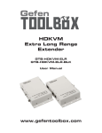
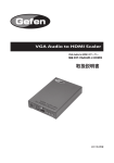
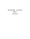
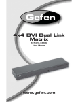
HDMI
TM
®
Over RGB
EXT-HDMI-5BNC
User Manual
www.gefen.com
ASKING FOR ASSISTANCE
Technical Support:
Telephone
Fax
(818) 772-9100
(800) 545-6900
(818) 772-9120
Technical Support Hours:
8:00 AM to 5:00 PM Monday thru Friday Pacific Time.
Write To:
Gefen, LLC
c/o Customer Service
20600 Nordhoff St
Chatsworth, CA 91311
www.gefen.com
[email protected]
Notice
Gefen, LLC reserves the right to make changes in the hardware, packaging and
any accompanying documentation without prior written notice.
HDMI Over RGB is a trademark of Gefen, LLC
© 2010 Gefen, LLC, All Rights Reserved
All trademarks are the property of their respective owners
Rev B1
CONTENTS
1
Introduction
2
Operation Notes
3
Features
4
Sender Panel Layout
5
Sender Panel Descriptions
6
Receiver Panel Layout
7
Receiver Panel Descriptions
8
Connecting And Operating The HDMI Over RGB
9
Troubleshooting The HDMI Over RGB
10 Specifications
11 Warranty
INTRODUCTION
Congratulations on your purchase of the HDMI Over RGB. Your complete
satisfaction is very important to us.
Gefen
Gefen delivers innovative, progressive computer and electronics add-on solutions
that harness integration, extension, distribution and conversion technologies.
Gefen’s reliable, plug-and-play products supplement cross-platform computer
systems, professional audio/video environments and HDTV systems of all sizes
with hard-working solutions that are easy to implement and simple to operate.
The Gefen HDMI Over RGB
The Gefen HDMI over RGB Extender is a handy extension solution which takes
an HDMI signal and extends it far away over legacy 4- or 5-connector coaxial
cabling. The HDMI over RGB Extender employes Gennum’s ActiveConnect
technology and is capable of delivering 1080p HDMI at distances up to 330 feet
(100 meters).
This is the ideal system for existing installations that are using RGBHV wiring
and would like to step up to a digital signal but not rip into the walls to rewire the
installation.
How It Works
Simply connect one end of the supplied HDMI cable to your HDMI video source.
Connect the other end of the supplied HDMI cable to the input side of the HDMI
over RGB Sender unit. Connect the HDMI over RGB Sender to the sending end
of your 4- or 5-plug coaxial cable run. If you are using a 5 cable configuration,
power will be supplied to the receiving unit. If you have a 4-cable configuration, a
second 5V power supply (sold separately) needs to be connected to the receiver
unit. At the receiving end of your coaxial cable extension, plug your HDMI over
RGB Receiver unit into your coaxial cable endpoints, then plug the HDMI over
RGB Receiver into your HDMI display. You will now see HDMI audio/video at
the remote location with perfect clarity and sound. You can connect and place
an optional Gefen IR Emitter/Blaster on the IR receiver of equipment you wish to
control from the remote location.
Note: This HDMI product supports BOTH Audio and Video signals.
1
OPERATION NOTES
READ THESE NOTES BEFORE INSTALLING OR
OPERATING THE HDMI OVER RGB
•
The HDMI Over RGB is designed for either 4 or 5 BNC cable type setups.
When 5 BNC cables are present and used, a power supply on the HDMI
Over RGB Receiver will not need to be used. Power will be transmitted over
the cables. When a 4 BNC cable setup is used, a second power supply
(part# EXT-PS52AU) for the receiving unit will need to be purchased and
connected.
•
HDMI 1.3 compliant. Please see page 3 for a listing of supported HDMI 1.3
features.
•
HDCP compliant.
•
The HDMI Over RGB has an IR repeater feature that will send standard
IR remote control commands from the receiver back to the sender. This
is useful for controlling equipment from a remote location. IR commands
cannot be relyed from the sender to the receiver. Please see page 8 for
more details.
•
Resolutions of up to 1080p Full HD are supported for HDTV use.
•
Resolutions of up to 1920 x 1200 are supported for computer use.
•
The HDMI Over RGB was designed for use with 75Ω coaxial cable.
2
FEATURES
Features
•
Connects HDMI sources to remote HDMI displays over legacy RGBHV
cabling
•
Supports extension distances of up to 330 feet
•
Supports resolutions up to 1080p, 2K, and 1920 x 1200
•
HDMI and HDCP compliant
•
Extends any IR device
HDMI 1.3 Features
•
Lip-Sync Pass Through
•
340 MHz (up to 16 bit YUV 444 supported @ 1080p)
•
Deep Color Supported (XV Color Supported)
•
Dolby TrueHD & DTS Master Supported
•
CEC Protocol Pass Through
Package Includes
(1) HDMI Over RGB Sender
(1) HDMI Over RGB Receiver
(1) 6 Foot HDMI Cable (M-M)
(1) 5V DC Power Supply
(1) User’s Manual
3
SENDER PANEL LAYOUT
Front Panel
2
1
3
4
Back Panel
5
6
7
4
8
9
SENDER PANEL DESCRIPTIONS
1
Locking 5V DC Power Supply Input
Connect the included 5V DC power supply to this input port.
2
HDMI Input Port
Connect the HDMI source device to this input port. A secure connection to this
HDMI port can be made using Gefen Mono•LOK cables.
3
IR Out Port
An IR emitter/blaster (sold separately, part# EXT-2IREMIT) must be connected
to this port to use the IR Repeater feature. Connect the emitter to this output port
and then connect the emitter “eye” on or near the IR receiver of the equipment
that is intended for control.
4
Link LED Indicator
This LED indicator will become active once a valid link has been established
between the sending and receiving units. If this LED does not activate there is a
possible mis-connection between the two units.
5
Red BNC Connector
This connector will transmit the RED signal data to the receiving unit. The cable
used for this connection cannot be omitted.
6
Green BNC Connector
This connector will transmit the GREEN signal data to the receiving unit. The
cable used for this connection cannot be omitted.
7
Blue BNC Connector
This connector will transmit the Blue signal data to the receiving unit. The cable
used for this connection cannot be omitted.
8
Clock BNC Connector
This connector will transmit the CLOCK signal data to the receiving unit. The
cable used for this connection cannot be omitted.
9
Receiver Power BNC Connector
This connector will transmit the power needed to operate the receiving unit. The
cable used for this connection can be omitted when using a 4 BNC type of cable
setup. If this cable is omitted power must separately be supplied to the receiver
by one of the included 5V DC power adapters.
5
RECEIVER PANEL LAYOUT
Front Panel
1
3
2
4
5
Back Panel
6
7
8
6
9
10
RECEIVER PANEL DESCRIPTIONS
1
Locking 5V DC Power Supply Input
When using a 5 BNC cable system this connector will not need to be used.
When using a 4 BNC cable system a second 5V DC power supply (part# EXTPS52AU) must be purchased and connected to this input port.
2
IR Receiver
This receiver is used for the IR Repeater feature. This receiver will accept
standard IR remote commands for transmission back to the sending unit and
then to the connected IR emitter/blaster.
3
HDMI Output Port
Connect the HDMI capable display device to this output port. A secure
connection to this HDMI port can be made using Gefen Mono•LOK cables.
4
IR Extension Port
An IR receiver extension (sold separately, part# EXT-RMT-EXTIR) can be
connected to this port to relocate the IR receiver. This option is available so that
the receiving unit can be placed out-of-sight while still retaining the usability of
the IR Repeating feature.
5
Link LED Indicator
This LED indicator will become active once a valid link has been established
between the sending and receiving units. If this LED does not activate there is a
possible mis-connection between the two units.
6
Red BNC Connector
This connector will transmit the RED signal data to the receiving unit. The cable
used for this connection cannot be omitted.
7
Green BNC Connector
This connector will transmit the GREEN signal data to the receiving unit. The
cable used for this connection cannot be omitted.
8
Blue BNC Connector
This connector will transmit the Blue signal data to the receiving unit. The cable
used for this connection cannot be omitted.
9
Clock BNC Connector
This connector will transmit the CLOCK signal data to the receiving unit. The
cable used for this connection cannot be omitted.
10 Receiver Power BNC Connector
This connector will transmit the power needed to operate the receiving unit. The
cable used for this connection can be omitted when using a 4 BNC type of cable
setup. If this cable is omitted power must separately be supplied to the receiver
by one of the included 5V DC power adapters.
7
CONNECTING AND OPERATING THE HDMI OVER RGB
How to Connect the HDMI Over RGB
1.
Connect the HDMI source device to the HDMI Over RGB sender unit using
the supplied HDMI cable.
2.
The HDMI Over RGB sender and receiver can be used with either a user
supplied 4 or 5 BNC cable system.
5 BNC Cables
Connect all 5 BNC cables to the R, G, B, C, and RP BNC connectors
between the HDMI Over RGB sender and receiver units.
4 BNC Cables
Connect the 4 BNC cables to the R, G, B, and C BNC connectors between
the HDMI Over RGB sender and receiver units. The RP BNC connector will
not be used and a second power supply (part# EXT-PS52AU) will need to be
purchased and connected to the receiver unit.
3.
Connect the HDMI capable display device to the HDMI Over RGB receiver
unit using a user supplied HDMI cable.
4.
Connect the included 5V DC power adapter to the HDMI Over RGB sender
unit.
NOTE: If using a 4 BNC cable system, a second power supply must be
purchased and connected to the HDMI Over RGB receiver unit.
5.
Power on the display first and then the source.
How to Operate the HDMI Over RGB
The HDMI Over RGB does not require any configuration for standard operation.
IR Repeater Feature
An IR emitter/blaster (sold separately, part# EXT-2IREMIT) is required to send
relayed IR commands to equipment at the sender’s location. Connect the IR
emitter jack to the HDMI Over RGB sender unit and connect the IR “eye” on
or near the IR receiver of the equipment that is intended for control. Point the
equipment’s IR remote at the IR receiver on the HDMI Over RGB receiver unit
and press buttons to relay commands back to the equipment device.
8
TROUBLESHOOTING THE HDMI OVER RGB
Troubleshooting the HDMI Over RGB
Adjustments can be made to the HDMI Over RGB in the event that video fails to
appear on the output device. On each unit, sender and receiver, a bank of DIP
switches are present. These DIP switches help boost functions in each unit. The
sender unit contains a boost for the +5V that is being sent over the BNC cable
to power the receiver, and the receiver contains a boost for Hot Plug Detection
(HPD). These DIP switches may need to be enabled when the signal between
both units are weak. Use the instructions below to enable these functions.
When there is no video on the output device, first try to boost HPD by enabling
DIP switch 1 on the receiver unit. The DIP switch bank is located on the
underside of the receiver unit and is covered with a piece of a metallic colored
tape.
1.
Locate the DIP switch bank on the receiver unit.
2.
Using a small pointed tool, change the position of DIP switch 1 to the ON
position.
3.
View the output device to see if the issue is resolved.
Operational power can be supplied by either an additional power supply or
by using 5 BNC cables (power is sent through the BNC port marked “RP”).
When the distance between the sending and receiving units are too great, the
operational power may be degraded enough to the point that the receiver unit will
fail to operate. The sender unit features a DIP switch that will apply a +5V boost
and ensure that enough power is being sent to the receiver unit. To enable this
feature DIP switch 2 on the sending unit must be in the ON position. The DIP
switch bank is located on the underside of the sender unit and is covered with a
piece of a metallic colored tape.
1.
Locate the DIP switch bank on the sender unit.
2.
Using a small pointed tool, change the position of DIP switch 2 to the ON
position.
3.
View the output device to see if the issue is resolved.
9
SPECIFICATIONS
HDMI 1.3 Features Supported:
Video Amp. Bandwidth......................... 340 MHz (up to 16 bit YUV 444 @ 1080p)
Digital Audio ............................................................. Dolby TrueHD & DTS Master
Protocols (Pass-Through): ..............................................................CEC, Lip-Sync
Video Resolutions (max) .................................................... 2K, 1080P, 1920x1200
Input Video Signal .................................................................................... 1.2V p-p
Input DDC Signal ........................................................................................ 5V p-p
Coaxial Connectors .......................................................................... 5 x BNC male
IR back channel ..................................................................................... IR blaster
HDMI™ Connector ........................................................... Type A (19 Pin) Female
Power Supply .............................................................................................. 5V DC
Power Consumption .......................................................... 10 Watts per unit (max)
Dimensions ..................................................................... 4.25”W x 1.25”H x 3.9”D
Shipping Weight ............................................................................................ 3 lbs.
HDCP Compliant
10
WARRANTY
Gefen warrants the equipment it manufactures to be free from defects in material
and workmanship.
If equipment fails because of such defects and Gefen is notified within two (2)
years from the date of shipment, Gefen will, at its option, repair or replace the
equipment, provided that the equipment has not been subjected to mechanical,
electrical, or other abuse or modifications. Equipment that fails under conditions
other than those covered will be repaired at the current price of parts and labor in
effect at the time of repair. Such repairs are warranted for ninety (90) days from
the day of reshipment to the Buyer.
This warranty is in lieu of all other warranties expressed or implied, including
without limitation, any implied warranty or merchantability or fitness for any
particular purpose, all of which are expressly disclaimed.
1.
Proof of sale may be required in order to claim warranty.
2.
Customers outside the US are responsible for shipping charges to and from
Gefen.
3.
Copper cables are limited to a 30 day warranty and cables must be in their
original condition.
The information in this manual has been carefully checked and is believed to
be accurate. However, Gefen assumes no responsibility for any inaccuracies
that may be contained in this manual. In no event will Gefen be liable for
direct, indirect, special, incidental, or consequential damages resulting from
any defect or omission in this manual, even if advised of the possibility of such
damages. The technical information contained herein regarding the features and
specifications is subject to change without notice.
For the latest warranty coverage information, please visit Gefen’s Warranty web
page at http://www.gefen.com/kvm/aboutus/warranty.jsp
PRODUCT REGISTRATION
Please register your product online by visiting Gefen’s web site at
http://www.gefen.com/kvm/Registry/Registration.jsp
11
Rev B1
20600 Nordhoff St., Chatsworth CA 91311
1-800-545-6900
818-772-9100
www.gefen.com
Pb
This product uses UL listed power supplies.
fax: 818-772-9120
[email protected]