1
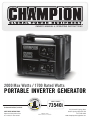
OWNER’S MANUAL & OPERATING INSTRUCTIONS
2000 Max Watts / 1700 Rated Watts
PORTABLE INVERTER GENERATOR
MODEL NUMBER
73540i
US Patent # D656897, 8391012
SAVE THESE INSTRUCTIONS
Important Safety Instructions
are included in this manual.
MADE IN CHINA
REV 73540i-20130309
10006 Santa Fe Springs Road
Santa Fe Springs CA 90670 USA
1-877-338-0999
www.championpowerequipment.com
FCC Statement
1. This device complies with Part 15 of the FCC Rules.
Operation is subject to the following two conditions:
(1) This device may not cause harmful interference.
(2) This device must accept any interference
received, including interference that may cause
undesired operation.
2. Changes or modifications not expressly approved by
the party responsible for compliance could void the
user’s authority to operate the equipment.
NOTE: This equipment has been tested and found to
comply with the limits for a Class B digital device,
pursuant to Part 15 of the FCC Rules. These limits
are designed to provide reasonable protection against
harmful interference in a residential installation.
This equipment generates uses and can radiate radio
frequency energy and, if not installed and used in
accordance with the instructions, may cause harmful
interference to radio communications. However, there
is no guarantee that interference will not occur in a
particular installation. If this equipment does cause
harmful interference to radio or television reception,
which can be determined by turning the equipment
off and on, the user is encouraged to try to correct the
interference by one or more of the following measures:
–– Reorient or relocate the receiving antenna.
–– Increase the separation between the equipment and
receiver.
–– Connect the equipment into an outlet on a
circuit different from that to which the receiver is
connected.
Consult the dealer or an experienced radio/TV technician
for help.
Have questions or need assistance?
Do not return this product to the store!
WE ARE HERE TO HELP!
Visit our website:
www.championpowerequipment.com
for more info:
• Product Info & Updates
• Frequently Asked Questions
• Tech Bulletins
• Product Registration
– or –
Call our Customer Care Team Toll-Free at:
1-877-338-0999
WARNING:
The Engine Exhaust from this product contains chemicals known to the State of California
to cause cancer, birth defects or other reproductive harm.
*We are always working to improve our products. Therefore, the enclosed product may differ slightly from the image on the cover.
73540i
2000 Max Watts / 1700 Rated Watts
PORTABLE INVERTER GENERATOR
Table of Contents
Introduction. . . . . . . . . . . . . . . . . . . . . . . . . . . . . 1
Introduction. . . . . . . . . . . . . . . . . . . . . . . . . . . 1
Portable Power Generator. . . . . . . . . . . . . . . . . . 1
Accessories . . . . . . . . . . . . . . . . . . . . . . . . . . . 1
This Booklet. . . . . . . . . . . . . . . . . . . . . . . . . . . 1
Manual Conventions. . . . . . . . . . . . . . . . . . . . . . . . 2
Safety Rules. . . . . . . . . . . . . . . . . . . . . . . . . . . . . 3
Controls and Features . . . . . . . . . . . . . . . . . . . . . . 5
Generator. . . . . . . . . . . . . . . . . . . . . . . . . . . . . 5
Parts Included . . . . . . . . . . . . . . . . . . . . . . . . . 5
Power Panel. . . . . . . . . . . . . . . . . . . . . . . . . . . 6
Assembly. . . . . . . . . . . . . . . . . . . . . . . . . . . . . . . 7
Remove the Generator from the Shipping Carton. . 7
Add Engine Oil. . . . . . . . . . . . . . . . . . . . . . . . . 7
Add Fuel . . . . . . . . . . . . . . . . . . . . . . . . . . . . . 8
Grounding . . . . . . . . . . . . . . . . . . . . . . . . . . . . 8
Operation. . . . . . . . . . . . . . . . . . . . . . . . . . . . . . . 9
Generator Location . . . . . . . . . . . . . . . . . . . . . . 9
Grounding . . . . . . . . . . . . . . . . . . . . . . . . . . . . 9
Starting the Engine. . . . . . . . . . . . . . . . . . . . . . 9
Economy Control Switch. . . . . . . . . . . . . . . . . . 10
Connecting Electrical Loads. . . . . . . . . . . . . . . 10
12V DC Outlet . . . . . . . . . . . . . . . . . . . . . . . . 11
12V DC Outlet – Battery Charging. . . . . . . . . . . 11
Stopping the Engine . . . . . . . . . . . . . . . . . . . . 11
Do Not Overload Generator. . . . . . . . . . . . . . . . 12
Capacity . . . . . . . . . . . . . . . . . . . . . . . . . . 12
Power Management. . . . . . . . . . . . . . . . . . . 12
Overload Operation. . . . . . . . . . . . . . . . . . . . . 12
Parallel Operation. . . . . . . . . . . . . . . . . . . . . . 12
Maintenance and Storage. . . . . . . . . . . . . . . . . . . 13
Engine Maintenance . . . . . . . . . . . . . . . . . . . . 13
Oil . . . . . . . . . . . . . . . . . . . . . . . . . . . . . . 13
Spark Plugs. . . . . . . . . . . . . . . . . . . . . . . . 13
Air Filter . . . . . . . . . . . . . . . . . . . . . . . . . . 14
Cleaning . . . . . . . . . . . . . . . . . . . . . . . . . . 14
Spark Arrester Cleaning. . . . . . . . . . . . . . . . 14
Adjustments. . . . . . . . . . . . . . . . . . . . . . . . 14
Maintenance Schedule. . . . . . . . . . . . . . . . . 15
Generator Maintenance . . . . . . . . . . . . . . . . . . 15
Storage . . . . . . . . . . . . . . . . . . . . . . . . . . . . .
Generator Storage. . . . . . . . . . . . . . . . . . . .
Specifications. . . . . . . . . . . . . . . . . . . . . . . . . . .
Engine Specifications . . . . . . . . . . . . . . . . . . .
Generator Specifications . . . . . . . . . . . . . . . . .
Fuel . . . . . . . . . . . . . . . . . . . . . . . . . . . . . . .
Oil. . . . . . . . . . . . . . . . . . . . . . . . . . . . . . . .
Spark Plugs. . . . . . . . . . . . . . . . . . . . . . . . . .
Maintenance Valve Clearance . . . . . . . . . . . . . .
An Important Message About Temperature. . . . .
Parts Diagram. . . . . . . . . . . . . . . . . . . . . . . . .
Parts List. . . . . . . . . . . . . . . . . . . . . . . . . . . .
Engine Parts Diagram . . . . . . . . . . . . . . . . . . .
Engine Parts List . . . . . . . . . . . . . . . . . . . . . .
Wiring Diagram. . . . . . . . . . . . . . . . . . . . . . . .
Troubleshooting. . . . . . . . . . . . . . . . . . . . . . . . . .
Warranty . . . . . . . . . . . . . . . . . . . . . . . . . . . . . .
Warranty Qualifications . . . . . . . . . . . . . . . . . .
Repair/Replacement Warranty. . . . . . . . . . . . . .
Do Not Return The Unit To
The Place Of Purchase. . . . . . . . . . . . . . . . . . .
Warranty Exclusions. . . . . . . . . . . . . . . . . . . .
Normal Wear . . . . . . . . . . . . . . . . . . . . . . .
Installation, Use and Maintenance. . . . . . . . .
Other Exclusions. . . . . . . . . . . . . . . . . . . . .
Limits of Implied Warranty
And Consequential Damage . . . . . . . . . . . . .
Contact Information. . . . . . . . . . . . . . . . . . . . .
Address. . . . . . . . . . . . . . . . . . . . . . . . . . .
Customer Service. . . . . . . . . . . . . . . . . . . .
Technical Service . . . . . . . . . . . . . . . . . . . .
15
15
16
16
16
16
16
16
16
16
17
18
19
20
21
22
23
23
23
23
23
23
23
23
23
23
23
23
23
ENGLISH 73540i
Introduction
Introduction
Accessories
Congratulations on your purchase of a Champion Power
Equipment inverter generator. CPE designs and builds
generators to strict specifications. With proper use and
maintenance, this generator will bring years of satisfying
service.
Champion Power Equipment manufactures and sells
accessories designed to help you get the most from your
purchase. To find out more about our covers and power
cables, please visit our web site at:
www.championpowerequipment.com
Portable Power Generator
This Booklet
This unit is a gasoline engine driven, alternating current
(AC) generator. It is designed to supply electrical power
for lighting, appliances, tools and similar equipment.
Every effort has been made to ensure the accuracy and
completeness of the information in this manual. We reserve
the right to change, alter and/or improve the product and
this document at any time without prior notice.
Record the model and serial numbers as well as date and place of purchase for future reference. Have this
information available when ordering parts and when making technical or warranty inquiries.
Champion Power Equipment Support
1-877-338-0999
Model Number
73540i
Serial Number
Date of Purchase
Purchase Location
For Oil Type see ‘Add Engine Oil‘ section. For Fuel Type see ‘Add Fuel‘ section.
1
REV 73540i-20130309
73540i ENGLISH
Manual Conventions
This manual uses the following symbols to help differentiate between different kinds of information. The safety symbol
is used with a key word to alert you to potential hazards in operating and owning power equipment.
Follow all safety messages to avoid or reduce the risk of serious injury or death.
DANGER
DANGER indicates an imminently hazardous
situation which, if not avoided, will result in death
or serious injury.
WARNING
WARNING indicates a potentially hazardous
situation which, if not avoided, could result in
death or serious injury.
CAUTION
CAUTION used without the safety alert symbol
indicates a potentially hazardous situation which, if
not avoided, may result in property damage.
NOTE
If you have questions regarding your generator, we can
help. Please call our help line at 1-877-338-0999
CAUTION
CAUTION indicates a potentially hazardous
situation which, if not avoided, may result in minor
or moderate injury.
REV 73540i-20130309
2
ENGLISH 73540i
Safety Rules
WARNING
Read this manual thoroughly before operating your
generator. Failure to follow instructions could result
in serious injury or death.
WARNING
The engine exhaust from this product contains
chemicals known to the state of California to cause
cancer, birth defects, or other reproductive harm.
DANGER
Generator exhaust contains carbon monoxide, a
colourless, odourless, poison gas. Breathing carbon
monoxide will cause nausea, dizziness, fainting or
death. If you start to feel dizzy or weak, get to fresh
air immediately.
Operate generator outdoors only in a well ventilated
area.
DO NOT operate the generator inside any building,
including garages, basements, crawlspaces and
sheds, enclosure or compartment, including the
generator compartment of a recreational vehicle.
DO NOT allow exhaust fumes to enter a confined
area through windows, doors, vents or other
openings.
DANGER CARBON MONOXIDE: using a generator
indoors CAN KILL YOU IN MINUTES.
DANGER
Rotating parts can entangle hands, feet, hair,
clothing and/or accessories.
Traumatic amputation or severe laceration can result.
Keep hands and feet away from rotating parts.
Tie up long hair and remove jewelry.
Operate equipment with guards in place.
DO NOT wear loose-fitting clothing, dangling
drawstrings or items that could become caught.
3
REV 73540i-20130309
DANGER
Generator produces powerful voltage.
DO NOT touch bare wires or receptacles.
DO NOT use electrical cords that are worn, damaged
or frayed.
DO NOT operate generator in wet weather.
DO NOT allow children or unqualified persons to
operate or service the generator
Use a ground fault circuit interrupter (GFCI) in damp
areas and areas containing conductive material such
as metal decking.
Use approved transfer equipment to isolate generator
from your electric utility and notify your utility
company before connecting your generator to your
power system.
WARNING
Sparks can result in fire or electrical shock.
When servicing the generator:
Disconnect the spark plug wire and place it where it
cannot contact the plug.
DO NOT check for spark with the plug removed.
Use only approved spark plug testers.
WARNING
Running engines produce heat. Severe burns can
occur on contact.
Combustible material can catch fire on contact.
DO NOT touch hot surfaces.
Avoid contact with hot exhaust gases.
Allow equipment to cool before touching.
Maintain at least 91 cm (3 ft.) of clearance on all
sides to ensure adequate cooling.
Maintain at least 1.5 m (5 ft.) of clearance from
combustible materials.
WARNING
Medical and Life Support Uses.
In case of emergency, call 911 immediately.
NEVER use this product to power life support
devices or life support appliances.
NEVER use this product to power medical devices
or medical appliances.
Inform your electricity provider immediately if you
or anyone in your household depends on electrical
equipment to live.
Inform your electrical provider immediately if a
loss of power would cause you or anyone in your
household to experience a medical emergency.
73540i ENGLISH
DANGER
Safety Rules
WARNING
Fuel and fuel vapours are highly flammable and
extremely explosive.
Fire or explosion can cause severe burns or death.
Unintentional startup can result in entanglement,
traumatic amputation or laceration.
Rapid retraction of the starter cord will pull hand and
arm towards the engine faster than you can let go.
Unintentional startup can result in entanglement,
traumatic amputation or laceration.
Broken bones, fractures, bruises or sprains could result.
When adding or removing fuel:
When starting engine, pull the starter cord slowly
until resistance is felt and then pull rapidly to avoid
kickback.
DO NOT start or stop the engine with electrical
devices plugged in.
Turn the generator off and let it cool for at least two
minutes before removing the fuel cap. Loosen the
cap slowly to relieve pressure in the tank.
Only fill or drain fuel outdoors in a well-ventilated area.
DO NOT pump gas directly into the generator at the
gas station. Use an approved container to transfer
the fuel to the generator.
DO NOT overfill the fuel tank.
Always keep fuel away from sparks, open flames,
pilot lights, heat and other sources of ignition.
DO NOT light or smoke cigarettes.
When starting the generator:
DO NOT attempt to start a damaged generator.
Make certain that the gas cap, air filter, spark plug,
fuel lines and exhaust system are properly in place.
Allow spilled fuel to evaporate fully before
attempting to start the engine.
Make certain that the generator is resting firmly on
level ground.
When operating the generator:
DO NOT move or tip the generator during operation.
DO NOT tip the generator or allow fuel or oil to spill.
When transporting or servicing the generator:
Make certain that the fuel shutoff valve is in the off
position and the fuel tank is empty.
Disconnect the spark plug wire.
When storing the generator:
Store away from sparks, open flames, pilot lights,
heat and other sources of ignition.
WARNING
Operation of this equipment may create sparks that
can start fires around dry vegetation.
A spark arrestor may be required. The operator
should contact local fire agencies for laws or
regulations relating to fire prevention requirements.
CAUTION
Exceeding the generator’s running capacity can
damage the generator and/or electrical devices
connected to it.
DO NOT overload the generator.
Start the generator and allow the engine to stabilize
before connecting electrical loads.
Connect electrical equipment in the off position,
and then turn them on for operation.
Turn electrical equipment off before stopping the
generator.
DO NOT tamper with the governed speed.
DO NOT modify the generator in any way.
CAUTION
Improper treatment or use of the generator can
damage it, shorten its life and void your warranty.
Use the generator only for intended uses.
Operate only on level surfaces.
DO NOT expose generator to excessive moisture,
dust, or dirt.
DO NOT allow any material to block the cooling slots.
If connected devices overheat, turn them off and
disconnect them from the generator.
DO NOT use the generator if:
–– Electrical output is lost
–– Equipment sparks, smokes or emits flames
–– Equipment vibrates excessively
REV 73540i-20130309
4
ENGLISH 73540i
Controls and Features
Read this owner’s manual before operating your generator. Familiarize yourself with the location and function of the
controls and features. Save this manual for future reference.
Inverter
1
2
3
5
4
6
7
(1) Carrying Handle
(5) Spark Plug Access Cap
(2) Fuel Lever Vent – Turn this valve to the “On”
position to supply air to the tank.
(6) Maintenance Cover – Oil filler, air filter, and
carburetor access.
(3) Fuel Cap – Remove to add fuel.
(7) Muffler
(4) Recoil Starter – Used to start the engine.
Parts Included
Your 73540i Gasoline Powered Generator ships with the
following parts:
–– Oil funnel. . . . . . . . . . . . . . . . . . . . . . . . . . . . . .
–– Spark plug socket. . . . . . . . . . . . . . . . . . . . . . . .
–– Automotive style USB adapter
(2.1A and 1A ports). . . . . . . . . . . . . . . . . . . . . . .
–– Automotive style battery charge cables. . . . . . . . . .
5
REV 73540i-20130309
1
1
1
1
73540i ENGLISH
Controls and Features
Power Panel
2
1
3
4
6
5
7
10
8
12
14
13
9
11
(1) Oil Warning Light – Check oil level when this light
turns on. Engine will not run when indicator is lit.
(8) Parallel Operation Control*
(2) Overload Indicator Light – This light turns ON
when the generator is overloaded and will cut
power to the receptacles.
(10) 120 V Duplex (NEMA 5-20R) – Use this duplex to
operate 120 Volt AC, single phase, 60 Hz loads.
(3) Output Light – Remains ON during normal
operating conditions. Shuts OFF when generator is
overloaded.
(4) Economy Control Switch
(9) Parallel Operation Outlets*
(11) Circuit Breaker (Flip) – Protects 5-20R receptacle
against electrical overload when parallel running.
(12) Ground Terminal – Consult an electrician for local
grounding regulations.
(5) Engine Switch
(13) Circuit Breaker (Push button) – Protects the
generator against electrical overload.
(6) Choke
(14) 12V DC Automotive Outlet**
(7) Fuel Valve Knob
*These outlets are used for connecting two Champion model 73540i generators for parallel operation. A Champion model 73500i
parallel kit (optional equipment) is required for parallel operation.
**Warning: Do not operate a device while it is plugged into the 12V DC outlet. Prolonged exposure to engine exhaust can cause
serious injury or death. While charging a device do no place on the exhaust side of the generator. Extreme heat caused by exhaust
can damage the device, and cause a potential fire hazard.
REV 73540i-20130309
6
ENGLISH 73540i
Assembly
Your generator requires some assembly. This unit ships
from our factory without oil. It must be properly serviced
with fuel and oil before operation.
If you have any questions regarding the assembly of your
generator, call our help line at 1-877-338-0999. Please
have your serial number and model number available.
Add Engine Oil Cont’d.
3. Remove oil fill cap/dipstick to add oil.
Remove the Generator from the Shipping Carton
1. Set the shipping carton on a solid, flat surface.
2. Remove everything from the carton except the
generator.
3. Using the handle of the unit, carefully remove the
generator from the box.
Add Engine Oil
4. Add 0.4 L (0.42 qt.) of oil and replace oil fill cap/
dipstick. DO NOT OVERFILL.
CAUTION
DO NOT attempt to crank or start the engine before
it has been properly filled with the recommended
type and amount of oil. Damage to the generator as
a result of failure to follow these instructions will
void your warranty.
NOTE
The recommended oil type is 10W-30 automotive
oil.
1. Place the generator on a flat, level surface.
2. Loosen the cover screws and remove the
maintenance cover.
5. Check engine oil level daily and add as needed.
CAUTION
The engine is equipped with a low oil shut-off and
will stop when the oil level in the crankcase falls
below the threshold level.
NOTE
Check oil often during the break-in period. Refer to
the Maintenance section for recommended service
intervals.
NOTE
The generator rotor has a sealed, pre-lubricated ball
bearing that requires no additional lubrication for
the life of the bearing.
7
REV 73540i-20130309
73540i ENGLISH
Add Fuel
1. Use clean, fresh, regular unleaded fuel with a
minimum octane rating of 85 and an ethanol
content of less than 10% by volume.
2. DO NOT mix oil with fuel.
3. Clean the area around the fuel cap.
4. Remove the fuel cap.
5. Slowly add fuel to the tank. DO NOT OVERFILL. Fuel
can expand after filling. A minimum of
1/4 in. (0.64 cm) of space left in the tank is required
for fuel expansion, more than 1/4 in. (0.64 cm) is
recommended. Fuel can be forced out of the tank as a
result of expansion if it is overfilled, and can affect the
stable running condition of the product. When filling
the tank, it is recommended to leave enough space for
the fuel to expand.
6. Screw on the fuel cap and wipe away any spilled
fuel.
CAUTION
Use regular unleaded gasoline with a minimum
octane rating of 85.
Do not mix oil and gasoline.
Fill tank to approximately 1/4 in. (0.64 cm) below
the top of the tank to allow for fuel expansion.
DO NOT pump gas directly into the generator at the
gas station. Use an approved container to transfer
the fuel to the generator.
DO NOT fill fuel tank indoors.
DO NOT fill fuel tank when the engine is running or hot.
DO NOT overfill the fuel tank.
DO NOT light cigarettes or smoke when filling the
fuel tank.
WARNING
Assembly
Add Fuel Cont’d.
NOTE
Our engines work well with 10% or less ethanol
blend fuels. When using blended fuels there are
some issues worth noting:
–– Ethanol-gasoline blends can absorb more water
than gasoline alone.
–– These blends can eventually separate, leaving
water or a watery goo in the tank, fuel valve and
carburetor.
–– With gravity-fed fuel supplies, this compromised
fuel can be drawn into the carburetor and cause
damage to the engine and/or potential hazards.
–– There are only a few suppliers of fuel stabilizer
that are formulated to work with ethanol blend
fuels.
–– Any damages or hazards caused by using
improper fuel, improperly stored fuel, and/
or improperly formulated stabilizers, are not
covered by manufacture’s warranty.
It is advisable to always shut off the fuel supply,
run the engine to fuel starvation and drain the tank
when the equipment is not in use for more than 30
days.
Grounding
Your generator must be properly connected to an
appropriate ground to help prevent electric shock.
WARNING
Failure to properly ground the generator can result
in electric shock.
A ground terminal connected to the frame of the generator
has been provided on the power panel. For remote
grounding, connect of a length of heavy gauge (12 AWG
minimum) copper wire between the generator ground
terminal and a copper rod driven into the ground. We
strongly recommend that you consult with a qualified
electrician to ensure compliance with local electrical codes.
Pouring fuel too fast through the fuel screen may
result in blow back of fuel at the operator while filling.
REV 73540i-20130309
8
ENGLISH 73540i
Operation
Generator Location
Grounding
NEVER operate the generator inside any building,
including garages, basements, crawlspaces and sheds,
enclosure or compartment, including the generator
compartment of a recreational vehicle. Please consult
your local authority. In some areas, generators must
be registered with the local utility. Generators used at
construction sites may be subject to additional rules and
regulations. Generators should be on a flat, level surface
at all times (even while not in operation). Generators
must have at least 1.5 m (5 ft.) of clearance from all
combustible material. In addition to clearance from
all combustible material, generators must also have at
least 91 cm (3 ft.) of clearance on all sides to allow for
adequate cooling, maintenance and servicing. Generators
The generator system ground connects the frame to the
ground terminals on the power panel.
–– The generator (stator winding) is isolated from the
frame and from the AC receptacle ground pin.
–– Electrical devices that require a grounded receptacle
pin connection will not function if the receptacle ground
pin is not functional.
should never be started or operated in the back of a
SUV, camper, trailer, in the bed of a truck (regular, flat
or otherwise), under staircases/stairwells, next to walls
or buildings, or in any other location that will not allow
for adequate cooling of the generator and/or the muffler.
DO NOT contain generators during operation. Allow
generators to properly cool before transport or storage.
Place the generator in a well-ventilated area. DO NOT
place the generator near vents or intakes where exhaust
fumes could be drawn into occupied or confined spaces.
Carefully consider wind and air currents when positioning
generator.
Failure to follow proper safety precautions may void
manufacturer’s warranty.
Starting the Engine
1. Make certain the generator is on a flat, level surface.
2. Disconnect all electrical loads from the generator.
Never start or stop the generator with electrical
devices plugged in or turned on.
3. Turn the fuel cap vent lever to the “On” position.
4. Turn the fuel valve to the “On” position.
WARNING
Do not operate or store the generator in rain, snow,
or wet weather.
Using a generator or electrical appliance in wet
conditions, such as rain or snow, or near a pool or
sprinkler system, or when your hands are wet, could
result in electrocution.
WARNING
During operation the muffler and exhaust fumes
produced will become hot. If adequate cooling and
breathing space are not supplied, or if the generator
is blocked or contained, temperatures can become
extremely heated and may lead to fire.
9
REV 73540i-20130309
5. Pull choke lever out to the “Choke” position.
73540i ENGLISH
Starting the Engine Cont’d.
6. Turn the engine switch to the “On” position.
Operation
Economy Control Switch Cont’d.
WARNING
For periods of high electrical load or momentary
fluctuations, the Economy Control Switch should be
turned OFF.
Connecting Electrical Loads
7. Pull the starter cord slowly until resistance is felt
and then pull rapidly.
1. Let the engine stabilize and warm up for a few
minutes after starting
2. Plug in and turn on the desired 120 Volt AC single
phase, 60 Hz electrical loads.
–– DO NOT connect 3-phase loads to the generator.
–– DO NOT connect 50 Hz loads to the generator.
–– DO NOT overload the generator.
NOTE
8. As engine warms up, push the choke lever in to the
“Run” position.
NOTE
Keep choke lever in “Choke” position for only 1
pull of the recoil starter. After first pull, move choke
lever to the “Run” position for up to the next 3
pulls of the recoil starter. Too much choke leads to
spark plug fouling/engine flooding due to the lack of
incoming air. This will cause the engine not to start.
NOTE
If the engine starts but does not stay running make
certain that the generator is on a flat, level surface.
The engine is equipped with a low oil sensor that
will prevent the engine from running when the oil
level falls below a critical threshold.
Economy Control Switch
The Economy Control switch can be activated in order to
minimize fuel consumption and noise while operating the
unit during times of reduced electrical output, allowing
the engine speed to idle during periods of non-use. The
engine speed returns to normal when an electrical load is
connected. When the economy switch is off, the engine
runs at normal speed continuously.
Connecting a generator to your electric utility
company’s power lines or to another power source
may be against the law. In addition this action,
if done incorrectly, could damage your generator
and appliances and could cause serious injury or
even death to you or a utility worker who may be
working on nearby power lines. If you plan to run a
portable electric generator during an outage, please
notify your electric utility company immediately
and remember to plug your appliances directly
into the generator. Do not plug the generator into
any electric outlet in your home. Doing so could
create a connection to the utility company power
lines. You are responsible for ensuring that your
generator’s electricity does not feed back into the
electric utility power lines.
If the generator will be connected to a building
electrical system, consult your local utility company
or a qualified electrician. Connections must isolate
generator power from utility power and must comply
with all applicable laws and codes.
WARNING
Do not operate a device while it is plugged in to the
12V DC outlet.
Prolonged exposure to engine exhaust can cause
serious injury or death.
WARNING
While charging a device do no place on the exhaust
side of the generator. Extreme heat caused by
exhaust can damage the device, and cause a
potential fire hazard.
REV 73540i-20130309
10
ENGLISH 73540i
Operation
12V DC Outlet
Stopping the Engine
The 12V DC outlet can be used with the supplied charge
cable and USB charger and other commercially available
12V DC automotive style plugs. The DC output is
unregulated and can damage some products. Confirm
your accessory input voltage range is at least 12-21V
DC. When using the DC outlet turn the Economy mode
switch to the “OFF” position.
1. Turn off and unplug all electrical loads. Never start
or stop the generator with electrical devices plugged
in or turned on.
2. Let the generator run at no-load for several minutes
to stabilize internal temperatures of the engine and
generator.
3. Turn the Fuel Valve to the “OFF” position.
4. Let the engine run until fuel starvation has stopped
the engine. This usually takes a few minutes.
5. Turn the engine switch to the “Off” position.
6. Allow the generator to cool down completely to room
temperature
7. Turn the fuel cap lever vent to the “Off” position
after the generator has cooled down completely.
Important: Always ensure that the Fuel Valve and the
Engine Switch are in the “OFF” position when the
engine is not in use.
12V DC Outlet – Battery Charging
1. Before connecting the battery charging cable to a
battery that is installed in a vehicle, disconnect the
vehicle battery ground cable from the negative (–)
battery terminal.
2. Plug the battery charging cable into the 12V DC
receptacle of the generator.
3. Connect the red (+) battery charger lead to the red
(+) battery terminal.
4. Connect the black (–) battery charger lead to the
black (–) battery terminal.
5. Start the generator.
Important: The 12V DC outlet is ONLY to be used with
the supplied 12V DC battery charging cable. The 12V
DC output is unregulated and will damage other 12V
DC products. When using the 12V DC outlet, turn the
Economy mode switch to the “OFF” position. Be sure all
electric devices including the lines and plug connections
are in good condition before connection to the generator.
11
REV 73540i-20130309
NOTE
If the engine will not be used for a period of two (2)
weeks or longer, please see the storage section for
proper engine and fuel storage.
73540i ENGLISH
Operation
Do Not Overload Generator
Overload Operation
Capacity
The overload indicator light will turn on when the rated
load is exceeded. When the maximum load is reached,
the LED will blink and cut power to the receptacles. To
recover the power, shut down the engine, wait until the
light turns off and restart the generator.
Follow these simple steps to calculate the running and
starting watts necessary for your purposes.
1. Select the electrical devices you plan on running at
the same time.
2. Total the running watts of these items. This is
the amount of power you need to keep your items
running.
3. Identify the highest starting wattage of all devices
identified in step 1. Add this number to the number
calculated in step 2. Surge wattage is the extra
burst of power needed to start some electric driven
equipment. Following the steps listed under “Power
Management” will guarantee that only one device
will be starting at a time.
Power Management
Use the following formula to convert voltage and
amperage to watts:
Volts x Amps = Watts
To prolong the life of your generator and attached
devices, follow these steps to add electrical load:
1. Start the generator with no electrical load attached.
2. Allow the engine to run for several minutes to
stabilize.
3. Plug in and turn on the first item. It is best to
attach the item with the largest load first.
4. Allow the engine to stabilize.
5. Plug in and turn on the next item.
6. Allow the engine to stabilize.
7. Repeat steps 5-6 for each additional item.
NOTE
Never exceed the specified capacity when adding
loads to the generator.
Parallel Operation
Two Champion model 73540i generators can be
operated in parallel to increase the total available
electrical power to 3000 watts. A Champion model
73500i parallel kit (optional equipment) is required
for parallel operation. For kit availability, call Customer
Service at 1-877-338-0999 or visit:
www.championpowerequipment.com.
Detailed instructions for parallel kit installation and
operation of the connected generators are provided
in the parallel kit Owner’s Manual and Operating
Instructions. Please note the following important
requirements:
1. The two generators may be stacked one on top
of the other by aligning the lower pads and upper
pockets at each corner of the generators.
2. Disconnect or turn off all electrical loads from both
generators.
3. The ECON switch must be in the same position on
both generators.
4. Before starting the engines, connect the AC power
outlet cables, the control cables and the ground
cables to both generators. Follow the instructions
supplied with the parallel kit.
5. Do not disconnect any cables after the engines have
been started.
6. Start both engines and observe the green output
indicator light on both generator panels.
7. Connect and turn on the electrical devices.
NOTE
The total electrical load must not exceed 3400 watts.
8. Follow the instructions on the previous page for
turning off the generators.
REV 73540i-20130309
12
ENGLISH 73540i
Maintenance and Storage
The owner/operator is responsible for all periodic
maintenance.
Oil Cont’d.
WARNING
Never operate a damaged or defective generator.
WARNING
Tampering with the factory set governor will void
your warranty.
Spark Plugs
WARNING
Improper maintenance will void your warranty.
NOTE
Maintenance, replacement, or repair of emission
control devices and systems may be performed
by any non-road engine repair establishment or
individual.
Complete all scheduled maintenance in a timely manner.
Correct any issue before operating the generator.
To prevent accidental starting, remove and ground spark
plug wire before performing any service.
1. Remove the maintenance cover.
2. Remove the spark plug cable from the spark plug.
3. Use the spark plug tool that shipped with your
generator to remove the plug. Remove the spark plug
access cap and insert the spark plug tool through
this hole.
4. Remove the spark plug.
5. Inspect the electrode on the plug. It must be clean
and not worn to produce the spark required for
ignition.
Oil
6. Make certain the spark plug gap is 0.6 - 0.7 mm
(0.024 - 0.028 in.).
NOTE
For service or parts assistance, contact our help
line at 1-877-338-0999
Engine Maintenance
Change oil when the engine is warm. Refer to the oil
specification to select the proper grade of oil for your
operating environment.
1. Loosen the cover screws and remove the
maintenance cover.
2. Remove the oil filler cap.
3. Tilt the generator on its side and allow the oil to
drain completely.
4. Add 0.4 L (0.42 qt.) of oil and replace oil fill cap/
dipstick. DO NOT OVERFILL.
5. Reinstall the maintenance cover and tighten the
cover screws.
6. Dispose of used oil at an approved waste
management facility.
13
REV 73540i-20130309
0.6 - 0.7 mm
0.024 - 0.028 in.
7. Carefully thread the plug into the engine.
8. Use the spark plug tool to firmly install the plug.
9. Attach the spark plug cap to the plug.
10.Reinstall the spark plug access cap, and
maintenance cover.
73540i ENGLISH
Air Filter
Maintenance and Storage
Spark Arrester Cleaning
1. Loosen M6x22 bolts to remove two pillars.
2. Remove 4 screws to remove the muffler cover
assembly.
3. Loosen the spark arrester clamp, remove the spark
arrester cover, and with a thin blade screwdriver
remove the spark arrester.
4. Carefully remove the carbon deposits from the spark
arrester screen with a wire brush.
1. Remove the maintenance cover.
2. Locate the air filter plastic cover. Remove the screw
using a Phillips head screwdriver.
3. Remove the foam element.
4. Wash in liquid detergent and water. Squeeze
thoroughly dry in a clean cloth.
5. Saturate in clean engine oil.
6. Squeeze in a clean, absorbent cloth to remove all
excess oil.
7. Place the filter in the assembly.
8. Reattach the air filter cover.
9. Reinstall the maintenance cover and tighten the
cover screw securely.
5. Replace the spark arrester if it is damaged.
6. Reattach spark arrester, cover assembly, and pillars.
Cleaning
CAUTION
DO NOT spray engine with water.
Water can contaminate the fuel system.
Use a damp cloth to clean exterior surfaces of the engine.
Use a soft bristle brush to remove dirt and oil.
Use an air compressor (25 PSI) to clear dirt and debris
from the engine.
CAUTION
Failure to clean the spark arrester will result in
degraded engine performance.
Adjustments
The air-fuel mixture is not adjustable. Tampering with
the governor can damage your generator and your
electrical devices and will void your warranty. CPE
recommends that you contact our service line at
1-877-338-0999 for all other service and/or adjustment
needs.
REV 73540i-20130309
14
ENGLISH 73540i
Maintenance and Storage
Maintenance Schedule
Storage
Follow the service intervals indicated in the following
maintenance schedule.
Service your generator more frequently when operating
in adverse conditions.
Contact our help line at 1-877-338-0999 to locate the
nearest Champion Power Equipment certified service
dealer for your generator or engine maintenance needs.
The generator should be started at least once every 14
days and allowed to run for at least 20 minutes. For
longer term storage, please follow these guidelines.
Every 8 hours or daily
Check oil level
Clean around air intake and muffler
First 5 Hours
Change oil
Every 50 hours or every season
Clean air filter
Change oil if operating under heavy load or in hot
environments
Every 100 hours or every season
Change oil
Clean/Adjust spark plug
Check/Adjust valve clearance*
Clean spark arrester
Clean fuel tank and filter*
Every 3 years
Replace fuel line
*To be performed by knowledgeable, experienced owners or
Champion Power Equipment certified dealers.
Generator Maintenance
Make certain that the generator is kept clean and stored
properly. Only operate the unit on a flat, level surface in
a clean, dry operating environment. DO NOT expose the
unit to extreme conditions, excessive dust, dirt, moisture
or corrosive vapours.
CAUTION
DO NOT use a garden hose to clean the generator.
Water can enter the generator through the cooling
slots and damage the generator windings.
Use a damp cloth to clean exterior surfaces of the generator.
Use a soft bristle brush to remove dirt and oil.
Use an air compressor (25 PSI) to clear dirt and debris
from the generator.
Inspect all air vents and cooling slots to ensure that they
are clean and unobstructed.
15
REV 73540i-20130309
Generator Storage
1. Add a properly formulated fuel stabilizer to the tank.
2. Be sure all appliances are disconnected from the
generator.
3. Run the generator for a few minutes so the treated
fuel cycles through the fuel system and carburetor.
4. Turn the fuel valve to the “Off” position.
5. Let the generator run until fuel starvation has
stopped the engine. This usually takes a few
minutes.
6. The generator needs to cool completely before
cleaning and storage.
7. Remove the spark plug cap, then pull the recoil grip 3
times to drain the gasoline from the carburetor jets.
8. Change the engine oil.
9. Remove the spark plug and pour about a tablespoon
of oil into the cylinder. Crank the engine slowly to
distribute the oil and lubricate the cylinder.
10. Reattach the spark plug.
11. Store the unit in a clean, dry place out of direct
sunlight.
DANGER
Generator exhaust contains odourless and
colourless carbon monoxide gas.
To avoid accidental or unintended ignition of your
generator during periods of storage, the following
precautions should be followed:
–– When storing the generator for short or extended
periods of time make sure that the Engine
Switch and the Fuel Valve are set in the OFF
position.
73540i ENGLISH
US Patent # D656897, 8391012
Engine Specifications
––
––
––
––
Model. . . . . . . . . . . . . . . . . . . . . . . YF149FD-330
Displacement. . . . . . . . . . . . . . . . . . . . . . . . 80cc
Type. . . . . . . . . . . . . . . . . . . . . . . . 4-Stroke OHV
Start Type . . . . . . . . . . . . . . . . . . . . . . . . . Recoil
Generator Specifications
––
––
––
––
––
––
––
––
––
––
––
––
Model. . . . . . . . . . . . . . . . . . . . . . . . . . . 73540i
Rated Load . . . . . . . . . . . . . . . . . . . . 1700 Watts
Maximum Load. . . . . . . . . . . . . . . . . . 2000 Watts
AC Load . . . . . . . . . . . . . . . . . . . . . . . . . . 120 V
Phase. . . . . . . . . . . . . . . . . . . . . . . . . . . . Single
Frequency . . . . . . . . . . . . . . . . . . . . . . . . . 60 Hz
Fuel Capacity. . . . . . . . . . . . . . . . . 1.0 gal. (3.8 L)
Gross Weight . . . . . . . . . . . . . . . . . 55.1 lb. (25 kg)
Net Weight. . . . . . . . . . . . . . . . . . 48.5 lb. (22 kg)
Height. . . . . . . . . . . . . . . . . 16.3 inches (41.5 cm)
Width . . . . . . . . . . . . . . . . . 13.2 inches (33.5 cm)
Length. . . . . . . . . . . . . . . . . . 19.3 inches (49 cm)
Fuel
Fuel capacity is 1.0 gal. (3.8 L). Use regular unleaded
Specifications
Spark Plugs
OEM spark plug: NHSP E6RTC
Replacement spark plug: NGK BPR6HS or equivalent
Make certain the spark plug gap is 0.6 - 0.7 mm or
(0.024 - 0.028 in.).
Maintenance Valve Clearance
–– Intake: 0.10 mm (0.004 in.)
–– Exhaust: 0.10 mm (0.004 in.)
Note: Tech bulletin regarding the valve adjustment
procedure is on www.championpowerequipment.com.
An Important Message About Temperature
Your Champion Power Equipment product is designed
and rated for continuous operation at ambient
temperatures up to 40°C (104°F). When your product is
needed your product may be operated at temperatures
ranging from -15°C (5°F) to 50°C (122°F) for short
periods. If the product is exposed to temperatures
outside this range during storage, it should be brought
back within this range before operation. In any event,
the product must always be operated outdoors, in a
well-ventilated area and away from doors, windows and
other vents.
gasoline with a minimum octane rating of 85 and an
ethanol content of less than 10% by volume.
Oil
Use 10W-30 automotive oil.
Oil capacity is 0.4 L (0.42 qt.).
DO NOT OVERFILL.
Please reference the following chart for recommended
oil types for use in the generator.
REV 73540i-20130309
16
17
REV 73540i-20130309
30 31 32
74
31
36
73
43
72
31
1
19
71
64
63
70
15
75
76
2
42
1
64
63
18
44 45 5
20
22 21
38 39
24 23
29 28 27 26 25
35 36 34 37
40
2 41
17 16
17
33
58
57
8
69
60
59
14
67
46 47 48
9
8
68 65
13 12 10 11
49
7
6
66
10
62
61
2 50 44
56
1
5
4
51 63 64 52
54
55
64
63
53
3
2
1
Specifications
ENGLISH 73540i
Parts Diagram
73540i ENGLISH
Parts List
#
Part Number
Description
4
39
81.211100.00.2
Operation Panel
1
17
40
81.126000.00
Ignition Assy.
1
1
41
81.210200.01
Toroid Coil,Comp.
1
4
42
81.211001.00
Control Box, Operation Panel
1
Nut M5
7
43
81.061200.00
Guide, Rope
1
81.200601.00.2
Base Setting Comp.
1
44
2.02.015
Nut M6
4
81.200604.00
Mounting Rubber, Base Setting
4
45
81.200101.01.2
Front Cover (Black)
1
8
1.5789.0622.3
Flange Bolt M6x22
8
46
81.200200.00.2
Cover (Black), Left Side
1
9
1.6177.1.06.3
Flange Nut M6
4
47
81.404
Engine
1
10
1.5789.0612
Flange Bolt M6×12
3
48
81.070400.00
Petcock
1
Fuel Tank
1
#
Part Number
Description
1
81.200800.00.2
Crossbanding
2
1.818.0514.3
Screw M5×14
3
81.200300.00.2
Cover (Black), Right Side
4
2.02.014
Nut M6
5
2.02.010
6
7
Qty
Qty
11
81.221000.01
Control Unit(120V/125V 60HZ)
1
49
81.071000.00.1
12
81.220003.00
Pinch, Controller
2
50
81.200401.00.2
Supporter (Black), Rear Cover
1
13
1.5789.0615
Flange Bolt (M6×15)
4
51
81.070300.00
Fuel Filter, Wire Mesh
1
14
81.200605.00
Bracket, Engine
4
52
81.200402.00.2
Protector (Black), Rear Cover
1
15
2.08.052.3
Bolt M6×16
4
53
1.818.0614.3
Screw M6×14
4
54
81.200502.00
Spillway, Fuel Tank
1
16
1.845.4220
Tapping Screw
1
17
122.210003.01
Plug
2
55
81.200503.00
Plug
1
Power Supply, Parallel
1
56
81.070100.00.3
Fuel Tank Cap
1
Control Box, Output Panel
1
57
1.5287.06.3
Flat Washer Ø6
4
2
58
81.200700.00.2
Handle Assembly
1
81.200501.00.2
Cover (Black),Top
1
18
19
20
5.1840.002
81.212001.00
1.6177.1.04.3
Nut M4
21
81.210012.00
Clamp, Receptacle
1
59
22
5.1220.914
AC.20A Breaker
1
60
2.08.068.2
Flange Bolt M5×13
3
61
5.1800.003
Rectifier
1
23
5.1120.010
Receptacle 5-20R
1
24
1.5783.0514.3
Bolt M5×14
1
25
1.6170.02.3
Nut M2
4
26
81.01.4.2
Output Panel
1
62
1.5783.0520
Bolt M5×20
1
63
81.200102.00
Round Grommet
4
64
81.200103.00
Groove Jacket
4
65
81.220001.00
Protector, Control Unit
2
27
1.6170.05.3
Nut M5
2
81.220002.00
Mount Rubber, Control Unit
2
1.9074.4.0306.3
Bolt And Washer Assembly
M3×6
66
28
1
67
81.200602.00
Mounting Rubber, End Cover
1
29
81.210001.00
Connect Port
2
68
81.200603.00
Mounting Rubber, Engine
1
30
1.9074.4.0210.3
Bolt And Washer Assembly
M2×10
4
69
2.05.050
Wire Clip (100)
1
70
81.212001.01
Control Box, Output Panel
1
1.9074.4.0414.3
Bolt And Washer Assembly
M4×14
14
Plug
1
31
71
122.210003.00
72
81.210100.C1.2
73
5.1200.308
DC.8A Breaker
1
74
5.1110.005
Cigarette-lighter Socket
1
1
Panel Assy.
32
5.1130.001
Receptacle
1
33
81.210200.00
Toroid Coil,Comp.
1
34
1.97.1.04.3
Washer Ø4
3
75
1.5287.04.2
Flat Washer Ø4
4
35
81.130200.00
Pull Choke Assembly
1
76
1.9074.3.0408.2
Bolt and Washer Assembly M4×8
4
36
1.818.0412.3
Screw M4×12
3
37
81.070001.00
Fuel Knob
1
38
5.1010.001.1
Switch
2
REV 73540i-20130309
18
19
REV 73540i-20130309
28
27
26
13 25
24
29 30
1
48
32
50
23 22
21 89
1
31
49
20
51
19
54 55
56
12 11
10
9
43 44
45 46
47
53 13
38 39
40 41
42
52
18 17
16 15
14 13
88
90
1 36
37
33 34
35
106
8 7
63
6
64
19
65
66
57
5
67
62
47
58
69
4 3
68
61
60
59
2 1
70
71
72
104 58 70
78
79
80
81
82
83
84
85 3
86
87
96
95
93
94
92
91
73
74
75
76
77
105
97
98
99
100
101
102
103
13
Specifications
ENGLISH 73540i
Engine Parts Diagram
73540i ENGLISH
Engine Parts List
#
Part Number
Description
1
1.5789.0612
Flange Bolt M6×12
2
81.061000.00
Recoil Assy.
#
Part Number
10
55
1
56
Qty
Description
Qty
81.081003.00
Fastening Insert
1
81.081001.00
Muff. Protector Seal
1
81.080003.00
Air Duct
1
3
1.5789.0615
Flange Bolt M6×15
5
57
4
2.02.013
Nut
1
58
1.6177.1.06.3
Flange Nut M6
6
5
81.080100.00
Fan Cover
1
59
81.020001.00
Breather Tube
1
6
2.02.018
Nut M12X1.25
2
60
81.021000.00
7
1.16674.0512
Flange Bolt M5x12
4
61
81.020002.00
Gasket, Cylinder Head Cover
1
8
81.080001.00
Cooling Fan
1
62
81.080200.00
Air Shroud, Cylinder
1
Cylinder Head Cover
1
9
81.060001.00
Pulley, Starter
1
63
1.5789.0650
Flange Bolt M6x50
4
10
2.11.019
Oil Seal(20X35X5)
2
64
81.010100.00
Cylinder Head
1
11
81.030100.00
Crankcase
1
65
81.030009.00
Gasket, Cylinder Head
1
1
66
2.01.026
Stud Bolt (M6X88)
2
12
67
81.130002.00
Gasket, Insulator
1
Bearing 6204
2
68
81.130001.00
Insulator, Carburetor
1
81.030013.01
Seal Strip 2, Crankcase Cover
1
69
81.130003.00
Gasket , Carburetor
1
81.030013.00
Seal Strip 1, Crankcase Cover
1
70
81.130000.00
Carburetor, Assy.
1
71
81.130004.00
Gasket, Air Cleaner
1
12
81.123000.01
Ignition Coil
13
1.5789.0620
Flange Bolt M6x20
14
1.276.6204
15
16
17
81.050100.00
Crankshaft
1
18
2.14.013
Sem. Key (3X5X13)
2
72
81.090004.00
Pipe, Air Cleaner
1
19
2.04.002
Dowel Pin Ø8×14
4
73
81.090003.00
Jt., Breather Pipe
1
81.091100.00
Base, Air Cleaner
1
20
81.030008.00
Gasket, Crankcase Cover
1
74
21
81.127000.00
Oil Level Sensor
1
75
81.091003.00
Element, Air Cleaner
1
22
81.030006.00
Plate, Coil
1
76
81.091200.00
Cover, Air Cleaner
1
Bolt (M6x20)
1
23
81.030007.00
Cover, Crankcase
1
77
2.08.053
24
81.122000.00
Trigger Assy.
1
78
2.02.009
Nut, Lock
2
25
1.16674.0612
Flange Bolt M6×12
2
79
81.040012.00
Screw, Valve Adjustment
2
26
81.191200.07
Stator Comp.
1
80
81.040009.00
Rocker Arm, Valve
2
27
1.5789.0635
Flange Bolt M6x35
2
81
81.040016.00
Shaft, Rocker Arm
1
28
81.191100.00
Rotor Comp.
1
82
83.040014.01
Valve Collar
2
29
81.190006.01
Rubber Seal 2, End Cover
1
83
83.040001.01
Retainer, Valve Spring
2
30
81.190006.00
Rubber Seal 1, End Cover
1
84
81.040017.00
Oil Seal, Valve
1
31
1.5789.0622.3
Flange Bolt M6x22
4
85
83.040003.01
Spring, Valve
2
32
81.190002.00
End Cover, Motor
1
86
81.040002.00
Valve, Intake
1
33
2.06.011
Clip(Ø25×b10)
1
87
81.040006.00
Valve, Exhaust
1
34
81.101501.00
Cap, Spark Arrester
1
88
81.031000.00
Oil Dipstick Assy.
1
35
81.101300.00
Spark Arrester
1
89
1.5789.0608
Flange Bolt M6×8
1
36
81.081002.00
Rubber Seal Sleeve
1
90
81.030035.00
Oil Nozzle
1
1.9074.4.0535
Screw M5×35
2
37
81.190001.00
Generator Fan
1
91
38
2.09.007
Circlip(Ø13.5×Ø1)
2
92
1.818.0306.3
Screw M3×6
2
39
81.050003.00
Wrist Pin
1
93
1.9074.3.0510
Screw M5×10
1
Clamp Board, Choke Control Line
1
40
81.050200.00
Connecting Rod
1
94
81.130007.00
41
81.050300.00
Piston Ring Set
1
95
81.130010.00
Spring, Connecter
1
42
81.050005.00
Piston
1
96
81.131000.00
Carburetor
1
43
81.040100.00
Camshaft
1
97
81.132001.00
Cover, Stepper Motor
1
44
81.040013.00
Lifter, Valve
2
98
81.132200.00
Stepper Motor
1
45
81.040005.00
Push Rod
2
99
1.9074.1.0408
Screw M4×8
2
46
2.15.005 (E6RTC)
Spark Plug (E6RTC)
1
100 81.132100.00
Stepper Motor Base
1
47
2.01.027
Stud.Bolt(M6X27)
6
101
Support, Stepper Motor
1
48
1.845.4817
Tapping Screw
4
102 81.130008.00
Connecter, Choke Valve Axis
1
81.130005.00
49
81.081300.00
Muff. Protector Assy. Right
1
103 81.130006.00
Brace, Support Plate
2
50
81.081200.00
Muff. Protector Assy.Middle
1
104 81.090005.00
Clamp Board, Air Filter Tube
1
51
1.6175.06.3
Nut M6
2
105 81.091000.00
Air Cleaner Assy.
1
106 81.101000.00
Muffler Assembly
1
52
81.101100.00
Muffler Assembly
1
53
81.100001.00
Gasket, EX.
1
54
81.081100.00
Muff. Protector, Side
1
REV 73540i-20130309
20
21
REV 73540i-20130309
B
BLACK
Br
Y YELLOW B/W
L BLUE
W/G
G
GREEN
G/Y
RED
R
W/L
W
WHITE
O
C CARNATION A
BROWN
BLACK WHITE
WHITE GREEN
GREEN YELLOW
WHITE BLUE
ORANGE
AMETHYST
IGNITION COIL
SUB COIL
AC COIL
DC COIL
GENERATOR
Y
G/Y
L
G
G
R
B
C
R B G
Y
R B Y G
B
8A
O Y L C
+
PARALLEL
OPERATION
CONTROL
R
CIRCUIT BREAKER
SPARKING
PLUG
CONTROL UNIT
R
STEPPING MOTOR
R
R
R
Y
Y
PARALLEL
POWER UNIT
DC DIODE
_
TCI UNIT
O
W
C
B/W
L
B
W
R
DC12V
R
W
CIRCUIT
BREAKER
G/Y
W
20A
OIL LEVEL SW
Y
ECO.SW STOP.SW
PARALLEL
TERMINAL
TRIGGER
B B/W C W O G L Y A
PORTFIRE
G/Y
EARTH
TERMINAL
G/Y
5-20R
ENGINE
G/Y
OUTPUT PANEL
CONTROL PANEL
Y
Specifications
ENGLISH 73540i
Wiring Diagram
73540i ENGLISH
Troubleshooting
Problem
Cause
Solution
Generator will not start
No fuel
Add fuel
Faulty spark plug
Replace spark plug
Unit loaded during start up
Remove load from unit
Low oil level
Fill crankcase to the proper level
Generator will not start;
Generator starts but runs roughly
Generator shuts down during operation
Generator cannot supply enough power or
overheating
No AC output
Repeated circuit breaker tripping
Place generator on a flat, level surface
Choke in the wrong position.
Adjust choke
Spark plug wire loose
Attach wire to spark plug
Out of fuel
Fill fuel tank
Low oil level
Fill crankcase to the proper level. Place
generator on a flat, level surface
Generator is overloaded
Review load and adjust. See “Power
Management”
Insufficient ventilation
Check for air restriction. Move to a well
ventilated area
Cable not properly connected
Check all connections
Connected device is defective
Replace defective device
Digital circuit breaker is open
Restart engine
Loose wiring
Inspect and tighten wiring connections
Other
Contact the help line
Overload
Review load and adjust. See “Power
Management”
Faulty cords or device
Check for damaged, bare or frayed wires.
Replace defective device
For further technical support:
Technical Service
Mon – Fri 8:30 AM – 5:00 PM (PST/PDT)
Toll Free: 1-877-338-0999
[email protected]
REV 73540i-20130309
22
ENGLISH 73540i
Warranty
WARRANTY
CHAMPION POWER EQUIPMENT
2 YEAR LIMITED WARRANTY
Warranty Qualifications
Champion Power Equipment (CPE) will register this
warranty upon receipt of your Warranty Registration Card
and a copy of your sales receipt from one of CPE’s retail
locations as proof of purchase.
Please submit your warranty registration and your proof
of purchase within ten (10) days of the date of purchase.
Repair/Replacement Warranty
CPE warrants to the original purchaser that the
mechanical and electrical components will be free of
defects in material and workmanship for a period of
one year (parts and labor) and two years (parts) from
the original date of purchase (90 days (parts and
labor) and 180 days (parts) for commercial & industrial
use). Transportation charges on product submitted
for repair or replacement under this warranty are the
sole responsibility of the purchaser. This warranty only
applies to the original purchaser and is not transferable.
Do Not Return The Unit To The Place Of Purchase
Contact CPE’s Technical Service and CPE will
troubleshoot any issue via phone or e-mail. If the
problem is not corrected by this method, CPE will, at its
option, authorize evaluation, repair or replacement of the
defective part or component at a CPE Service Center.
CPE will provide you with a case number for warranty
service. Please keep it for future reference. Repairs
or replacements without prior authorization, or at an
unauthorized repair facility, will not be covered by this
warranty.
Warranty Exclusions
This warranty does not cover the following repairs and
equipment:
Normal Wear
Generators need periodic parts and service to perform well.
This warranty does not cover repair when normal use has
exhausted the life of a part or the equipment as a whole.
Installation, Use and Maintenance
This warranty will not apply to parts and/or labor if this
generator is deemed to have been misused, neglected,
involved in an accident, abused, loaded beyond the
generator’s limits, modified, installed improperly or
connected incorrectly to any electrical component.
23
REV 73540i-20130309
Installation, Use and Maintenance Cont’d.
Normal maintenance such as spark plugs, air filters,
adjustments, fuel system cleaning and obstruction due
to buildup is not covered by this warranty.
Other Exclusions
This warranty excludes:
–– Cosmetic defects such as paint, decals, etc.
–– Wear items such as filter elements, o-rings, etc.
–– Accessory parts such as starting batteries, and
storage covers.
–– Failures due to acts of God and other force majeure
events beyond the manufacturer’s control.
–– Problems caused by parts that are not original
Champion Power Equipment parts.
This warranty does not apply to generators used for
prime power in place of a utility.
Limits of Implied Warranty and Consequential Damage
Champion Power Equipment disclaims any obligation to
cover any loss of time, use of this product, freight, or
any incidental or consequential claim by anyone from
using this generator. THIS WARRANTY IS IN LIEU OF
ALL OTHER WARRANTIES, EXPRESS OR IMPLIED,
INCLUDING WARRANTIES OF MERCHANTABILITY OR
FITNESS FOR A PARTICULAR PURPOSE.
A unit provided as an exchange will be subject to the
warranty of the original unit. The length of the warranty
governing the exchanged unit will remain calculated by
reference to the purchase date of the original unit.
This warranty gives you certain legal rights which may
change from state to state. Your state may also have
other rights you may be entitled to that are not listed
within this warranty.
Contact Information
Address
Champion Power Equipment, Inc.
Customer Service
10006 Santa Fe Springs Rd.
Santa Fe Springs, CA 90670
www.championpowerequipment.com
Customer Service
Mon – Fri 8:30 AM – 5:00 PM (PST/PDT)
Toll Free: 1-877-338-0999
[email protected]
Fax no.: 1-562-236-9429
Technical Service
Mon – Fri 8:30 AM – 5:00 PM (PST/PDT)
Toll Free: 1-877-338-0999
[email protected]
24/7 Tech Support: 1-562-204-1188
Champion Power Equipment, Inc. (CPE),
The United States Environment Protection Agency (U.S. EPA.) and the California Air Resources Board (CARB)
Emission Control System Warranty
Your Champion Power Equipment (CPE) engine complies with both the U.S. EPA and state of California Air
Resources Board (CARB) emission regulations.
YOUR WARRANTY RIGHTS AND OBLIGATIONS:
The US EPA, California Air Resources Board, and CPE are pleased to explain the Federal and California Emission
Control Systems Warranty on your 2013 small off-road engine and engine powered equipment. In California, new,
small off-road engines and new equipment that use small off-engines must be designed, built and equipped to meet
the State’s stringent anti smog standards. In the other states, new engines and equipment must be designed, built
and equipped, at the time of sale, to meet U.S. EPA regulations for small non-road engines. CPE warrants the
emission control system on your small off-road engine and equipment for the period of time listed below, provided
there has been no abuse, neglect, unapproved modification, or improper maintenance of your equipment.
Your emission control system may include parts such as the carburetor, fuel-injection system, the ignition system,
catalytic converter and fuel lines. Also included may be hoses, belts, connectors and other emission related
assemblies. Where a warrantable condition exits, CPE will repair your small off-road engine at no cost to you
including diagnosis, parts and labor. For engines less than or equal to 80cc, only the fuel tank and fuel line is
subject to the evaporative emission control warranty requirements of this section.
MANUFACTURER’S EMISSION CONTROL SYSTEM WARRANTY COVERAGE:
This emission control system is warranted for two years, subject to provisions set forth below. If, during the
warranty period, emission related part on your engine is defective in materials or workmanship, the part will be
repaired or replaced by CPE.
OWNER WARRANTY RESPONSIBILITIES:
As the small off-road engine owner, you are responsible for the performance of the required maintenance listed in
your Owner’s Manual. CPE recommends that you retain all your receipts covering maintenance on your small offroad engine, but CPE cannot deny warranty solely for the lack of receipts or for your failure to ensure the
performance of all scheduled maintenance.
As the small off-road engine owner, you should however be aware that CPE may deny you warranty coverage if
your small, off-road engine or a part has failed due to abuse, neglect, improper maintenance or unapproved
modifications.
You are responsible for presenting your small off-road engine to an Authorized CPE service outlet or alternate
service outlet as described in (3)(f.) below, CPE dealer or CPE, Santa Fe Springs, Ca. as soon as a problem exists.
The warranty repairs should be completed in a reasonable amount of time, not to exceed 30 days.
If you have any questions regarding your warranty rights and responsibilities, you should contact:
Champion Power Equipment, Inc.
Customer Service
10006 Santa Fe Springs Road
Santa Fe Springs, CA 90670
1-877-338-0999
[email protected]
EMISSION CONTROL SYSTEM WARRANTY
The following are specific provisions relative to your Emission Control System (ECS) Warranty Coverage.
1. APPLICABILITY: This warranty shall apply to 1995 and later model year California small off-road engines (for
other states, 1997 and later model year engines). The ECS Warranty Period shall begin on the date the new engine
or equipment is delivered to its original, end-use purchaser, and shall continue for 24 consecutive months
thereafter.
2. GENERAL EMISSIONS WARRANTY COVERAGE
CPE warrants to the original, end-use purchaser of the new engine or equipment and to each subsequent
purchaser that each of its small off-road engines is:
a. Designed, built and equipped so as to conform to U.S. EPA emissions standards for spark-ignited
engines at or below 19 kilowatts and all applicable regulations adopted by the California Air Resources Board
and
b. Free from defects in materials and workmanship that cause the failure of a warranted part to be identical
in all material respects to the part as described in the engine manufacturer’s application for certification for a period
of two years.
3. THE WARRANTY ON EMISSION-RELATED PARTS WILL BE INTERPRETED AS FOLLOWS:
a. Any warranted part that is not scheduled for replacement as required maintenance in the Owners
Manual shall be warranted for the ECS Warranty Period. If any such part fails during the ECS Warranty Period, it
shall be repaired or replaced by CPE according to Subsection “d” below. Any such part repaired or replaced under
the ECS Warranty shall be warranted for any remainder of the ECS Warranty Period.
b. Any warranted, emissions-related part which is scheduled only for regular inspection as specified in the
Owners Manual shall be warranted for the ECS Warranty Period. A statement in such written instructions to the
effect of “repair or replace as necessary”, shall not reduce the ECS Warranty Period. Any such part repaired or
replaced under the ECS Warranty shall be warranted for the remainder of the ECS Warranty Period.
c. Any warranted, emissions-related part which is scheduled for replacement as required maintenance in
the Owner’s Manual shall be warranted for the period of time prior to the first scheduled replacement point for that
part. If the part fails prior to the first scheduled replacement, the part shall be repaired or replaced by CPE
according to Subsection “d” below. Any such emissions-related part repaired or replaced under the ECS Warranty,
shall be warranted for the remainder of the ECS Warranty Period prior to the first scheduled replacement point for
such emissions-related part.
d. Repair or replacement of any warranted, emissions-related part under this ECS Warranty shall be
performed at no charge to the owner at a CPE Authorized Service Outlet.
e. The owner shall not be charged for diagnostic labor which leads to the determination that a part covered
by the ECS Warranty is in fact defective, provided that such diagnostic work is performed at a CPE Authorized
Service Outlet.
f. CPE shall pay for covered emissions warranty repairs at non-authorized service outlets under the
following circumstances:
i. The service is required in a population center with a population over 100,000 according to U.S.
Census 2000 without a CPE Authorized Service Outlet AND
ii. The service is required more than 100 miles from a CPE Authorized Service Outlet. The 100 mile
limitation does not apply in the following states: Alaska, Arizona, Colorado, Hawaii, Idaho, Montana, Nebraska,
Nevada, New Mexico, Oregon, Texas, Utah and Wyoming.
g. CPE shall be liable for damages to other original engine components or approved modifications
proximately caused by a failure under warranty of an emission-related part covered by the ECS Warranty.
h. Throughout the ECS Warranty Period, CPE shall maintain a supply of warranted emission-related parts
sufficient to meet the expected demand for such emission-related parts.
i. Any CPE Authorized and approved emission-related replacement part may be used in the performance of
any ECS Warranty maintenance or repair and will be provided without charge to the owner. Such use shall not
reduce CPE’s warranty obligation.
j. Unapproved add-on or modified parts may not be used to modify or repair a CPE engine. Such use voids
this ECS Warranty and shall be sufficient grounds for disallowing an ECS Warranty claim. CPE shall not be liable
hereunder for failures of any warranted parts of a CPE engine caused by the use of such an unapproved add-on or
modified part.
EMISSION-RELATED PARTS INCLUDE THE FOLLOWING: (using those portions of the list applicable to the
engine)
Systems covered by this
warranty
Fuel Metering System
Fuel regulator, Carburetor and internal parts
Air Induction System
Air cleaner, Intake manifold
Ignition System
Spark plug and parts, Magneto ignition system
Exhaust System
Exhaust manifold, catalytic converter
Miscellaneous Parts
Tubing, Fittings, Seals, Gaskets, and Clamps associated with these listed
systems.
Fuel Tank, Fuel Cap, Fuel Line, Fuel Line Fittings, Clamps, Pressure
Relief Valves, Control Valves, Control Solenoids, Electronic Controls,
Vacuum Control Diaphragms, Control Cables, Control Linkages, Purge
Valves, Vapor Hoses, Liquid/Vapor Separator, Carbon Canister, Canister
Mounting Brackets, Carburetor Purge Port Connector
Evaporative Emissions
Parts Description
TO OBTAIN WARRANTY SERVICE:
You must take your CPE engine or the product on which it is installed, along with your warranty registration card or
other proof of original purchase date, at your expense, to any Champion Power Equipment dealer who is
authorized by Champion Power Equipment, Inc. to sell and service that CPE product during his normal business
hours. Alternate service locations defined in Section (3)(f.) above must be approved by CPE prior to service. Claims
for repair or adjustment found to be caused solely by defects in material or workmanship will not be denied because
the engine was not properly maintained and used.
If you have any questions regarding your warranty rights and responsibilities, or to obtain warranty
service, please write or call Customer Service at Champion Power Equipment, Inc.
Champion Power Equipment, Inc.
10006 Santa Fe Springs Road
Santa Fe Springs, CA 90670
1-877-338-0999
Attn.: Customer Service
[email protected]