1
AlliedWare PlusTM OS
How To | Configure Hardware Filters (ACLS) on SwitchBlade
x908, x900-12XT/S, and x900-24 Series Switches
Contents
Contents .................................................................................................................................................... 1
Introduction .............................................................................................................................................. 3
Which products and software versions does this Note apply to? ....................................... 4
Benefits of Named Sequential Hardware ACLs ................................................................................ 5
Extended support limit ................................................................................................................... 5
Flexible hardware filter ................................................................................................................... 5
Structure of a Named Sequential Hardware ACL ...........................................................................
IP protocol filter entry ....................................................................................................................
MAC filter entry ...............................................................................................................................
ICMP protocol filter entry .............................................................................................................
TCP/UDP protocol filter entry .....................................................................................................
6
6
6
6
6
Creating Named Sequential Hardware ACLs ...................................................................................
Configuring a Named Hardware ACL - without sequence numbers .................................
Configuring a Named Sequential Hardware ACL - with sequence numbers .....................
Removing a sequential entry .........................................................................................................
Overwriting an entry in a Named Sequential Hardware ACL ..............................................
7
7
7
7
8
Creating Numbered IP Hardware ACLs ............................................................................................ 9
IP packets ........................................................................................................................................... 9
ICMP packets .................................................................................................................................... 9
TCP and UDP packets .................................................................................................................. 10
Creating Numbered MAC address Hardware ACLs ..................................................................... 11
The effects of the action keywords in ACLs ................................................................................... 12
Applying Named Sequential Hardware Filters to port interfaces .............................................. 13
Viewing port information ............................................................................................................. 13
C613-16119-00 REV D
www.alliedtelesis.com
Contents
Applying Named Sequential Hardware Filters to a channel-group ............................................ 14
Applying Named Sequential Hardware Filters globally ................................................................. 14
Applying Numbered Hardware Filters to port interfaces ............................................................ 15
Attaching ACLs ............................................................................................................................... 15
Applying Numbered Hardware Filters globally ............................................................................... 16
Changing Numbered Hardware ACL order .................................................................................... 17
Applying numbered and named ACLs to the same port .............................................................. 17
Warning on the default filtering principles of different ACL types ............................................ 17
Applying filters by using QoS class-maps .........................................................................................
Create a class-map .........................................................................................................................
Specify what the class-map will match on ................................................................................
Match on "inner" keywords for nested VLANs ..............................................................
Match on TCP flag .................................................................................................................
Match on eth-format and protocol ...................................................................................
Apply the class-maps to a policy-map .......................................................................................
Apply the policy-map to ports ....................................................................................................
18
19
19
20
21
21
22
22
The logic of the operation of the hardware filters ........................................................................ 23
Combining interface ACLs and QoS class-maps ............................................................................ 24
Examples .................................................................................................................................................. 25
Blocking all multicast traffic ......................................................................................................... 25
Blocking all multicast traffic except one address .................................................................... 25
Mirroring HTTP and SMTP traffic .............................................................................................. 26
Mirroring ARP packets .................................................................................................................. 27
Blocking TCP sessions in one direction .................................................................................... 28
Combining Named Hardware ACL entries to match on MAC, VLAN, IP and TCP fields .
29
How many filters can you create? ......................................................................................................
1. The filter rule tables .................................................................................................................
Numbered Hardware ACLs ................................................................................................
Named Sequential Hardware ACLs ..................................................................................
The allocation of silicon filter table entries .....................................................................
Factors that cause multiple silicon filter table entry consumption ............................
About port range table entry consumption: ...................................................................
How many table entries have been taken? ......................................................................
2. The profile (mask) .....................................................................................................................
Are there enough bytes for your set of filters? ..............................................................
Some other features also use filters, so use some of the length ...............................
31
31
31
32
34
34
35
36
36
38
39
Reference section .................................................................................................................................. 40
Page 2 | AlliedWare Plus™ OS How To Note
Introduction
Introduction
The SwitchBlade x908, x900-12XT/S, and x900-24 series switches support a powerful
hardware based packet-filtering facility.
These switches can filter on a range of Layer 2, Layer 3, and Layer 4 packet attributes, and
perform a variety of different actions on the packets that match the filters.
Because the filters are hardware-based, they put no load on the switch’s CPU, and do not
affect the throughput of the switch. It is possible to configure over 2000 different filters, and
still have complete wire speed throughput on the switch.
On the AlliedWare Plus Operating System, hardware-based packet filtering is carried out
with hardware Access Control Lists (ACLs). The following three configuration methods are
available:
Named Sequential Hardware ACLs
This version of Hardware ACL configuration implements sequential entries to provide a
flexible filtering hierarchy. Named Sequential Hardware ACLs enable the Hardware ACLs
to use the full number of ACL entries available in hardware. The Numbered Hardware
ACLs, by contrast, are limited to specific ranges of numbered ACLs that are less than the
total number available in hardware.
Named Sequential Hardware ACLs support a wide range of filter actions and filter
selectors such as IP address, MAC address, TCP/UDP port, or ICMP type.
On the x900, Named Sequential Hardware ACLs may be applied globally or per interface
port.
Numbered Hardware ACLs
This ACL option allows you to create a simple filter based on IP address, MAC address,
TCP/UDP port, or ICMP type, using one or more Numbered Hardware ACLs. On x900
series switches, you can apply Numbered Hardware ACLs globally or per interface port.
The numbered ranges available are as follows:
<3000-3699>
Hardware IP access list
<4000-4699>
Hardware MAC access list
You can also create a filter hierarchy, by applying multiple Numbered Hardware ACLs to
a port. For example, you can make one ACL that allows traffic which flows from a source
IP address to a destination address, then a second ACL that drops all other traffic from
that source IP address. This filter hierarchy method is not as convenient or flexible as that
offered by Named Sequential Hardware ACLs.
Sequential entry numbering is not supported by Numbered Hardware ACLs.
QOS Match Commands
To make a filter based on a range of other packet fields, you can use QoS match commands
in one or more QoS class-maps, mostly in combination with ACLs. Then, use QoS to apply
the class-maps to a policy-map, and then to a port.
This note describes the three approaches shown above. Then it gives a series of examples,
and ends by discussing how many filters you can make.
Page 3 | AlliedWare Plus™ OS How To Note
Introduction
Which products and software versions does this Note apply to?
Products: SwitchBlade x908, x900-12XT/S, and x900-24 series switches
Software versions: 5.2.1-0.1 and above offer the traditional Numbered Hardware ACLs
Software version 5.3.4 (and later) introduces sequential entries for Named Hardware
ACLs, but not for Numbered Hardware ACLs. Sequential entry support is also introduced
for Software ACLs – e.g.: standard and extended, Named or Numbered Software ACLs.
Software version 5.3.4 supports Global Application of Hardware ACLs.
Hardware filters are also available on Layer 3 switches running the AlliedWare OS. For
AlliedWare OS configurations, see the AlliedWare OS How To Notes:
How To Use the Hardware Filters on the AT-8948 and AT-9900 Series Switches
How To Configure Filtering Actions on QoS Flow Groups and Traffic Classes
The number of Hardware Filters available on x600 is different and is discussed in:
Pending: Separate Tips and Tricks Note on x600 Slot Consumption Information
These Notes are available from www.alliedtelesis.com/resources/literature/howto.aspx.
Page 4 | AlliedWare Plus™ OS How To Note
Benefits of Named Sequential Hardware ACLs
Benefits of Named Sequential Hardware ACLs
The recommended ACL type to use is Named Sequential Hardware ACLS. The main benefits
of using Named Sequential Hardware ACLs over Numbered Hardware ACLS are the
extended support limit, and a flexible hardware filter.
Extended support limit
Named Sequential Hardware ACLs remove the arbitrary limitation that Numbered ACLs
impose on the maximum number of hardware ACLs you can create.
With Numbered ACLs, the x900 can support up to 1400 Numbered Hardware ACLs, if both
the IP and the MAC ACLs are employed. In contrast, Named Sequential Hardware ACLs
comprise a sequenced set of entries within an ACL. The sequence number itself is not
restricted to a certain range – the number only serves to tag a sequence order. This means it
does not impose an upper limit on supported Hardware ACLs in the way that Numbered
ACLs does. The only restriction that remains is the number of hardware filtering entries that
the silicon can support.
For more information, refer to “"How many filters can you create?" on page 31.
Flexible hardware filter
Named Sequential Hardware ACLs provide flexibility with regard to order and the ability to
add and delete entries within a current ACL. This is demonstrated in the example in
"Creating Named Sequential Hardware ACLs" on page 7.
Note:
Sequence number support is not available with mac-based and ip-based Numbered
Hardware ACLs.
Page 5 | AlliedWare Plus™ OS How To Note
Structure of a Named Sequential Hardware ACL
Structure of a Named Sequential Hardware ACL
A Named Sequential Hardware ACL consists of a series of filter entries. The only limit on the
number of filter entries that you can add to the ACL is on the number of entries that can fit
into the hardware table - the software does not put any other lower limit on the number of
entries.
Entries in the ACL can be from 4 different types:
IP protocol filter entry
This can match on any combination of the fields:
IP protocol number, for example 1 for ICMP, 2 for IGMP, 50 for ESP, 89 for OSPF, etc. Or,
you can simply specify "IP", to match any IP protocol
Source IP address - an individual IP address or a subnet
Dest IP address- an individual IP address or a subnet
Source MAC address- an individual MAC address or a range
Dest MAC address- an individual MAC address or a range
VLAN ID
MAC filter entry
This can match on any combination of the fields:
Source MAC address- an individual MAC address or a range
Dest MAC address- an individual MAC address or a range
VLAN ID
Inner VLAN ID
ICMP protocol filter entry
This can match on any combination of the fields:
Source IP address- an individual IP address or a subnet
Dest IP address- an individual IP address or a subnet
ICMP type
VLAN ID
TCP/UDP protocol filter entry
Source IP address- an individual IP address or a subnet
Dest IP address- an individual IP address or a subnet
Source TCP/UDP port - either single port number or a range
Dest TCP/UDP port - either single port number or a range
VLAN ID
You can find the exact syntax of the commands to create these entries in the x900/x908
software reference manual.
There is no restriction on the combinations of filter entry types that can exist together in the
same Named Sequential Hardware ACL.
Page 6 | AlliedWare Plus™ OS How To Note
Creating Named Sequential Hardware ACLs
Creating Named Sequential Hardware ACLs
The first step to configuring a named hardware ACL is to create the ACL, using the
command:
access-list Hardware <name>
This command puts you into hardware ACL configuration sub-mode (ip-hw-acl mode). In this
mode you can create entries for the ACL.
Configuring a Named Hardware ACL - without sequence numbers
Sequence numbers are optional for Named Hardware ACLs, but if you do not enter one, the
switch assumes a sequence number. You must use hardware ACL configuration sub-mode (iphw-acl).
Sequence numbers are temporary and are not saved.
Example:
(config)#access-list hardware test_filter
(config-ip-hw-acl)#deny ip 192.168.10.1/32 any
Even though no sequence number has been entered, the switch does temporarily associate a
number with the entry. You can see that the sequence number 10 is allocated to the filter
entry in the following example:
#show access-list test_filter
Hardware IP access list test_filter
10 deny ip 192.168.10.1/32 any
Configuring a Named Sequential Hardware ACL - with sequence
numbers
Configuring with sequence numbers is advantageous because it allows you to insert an entry
before the last entry.
Example:
(config-ip-hw-acl)#5 permit ip 192.168.88.88/32 any
This new entry has a sequence number less than that which was associated with the previous
entry, so it is inserted into the ACL above the previous entry.
#show access-list test_filter
Hardware IP access list test_filter
5 permit ip 192.168.88.88/32 any
10 deny ip 192.168.10.1/32 any
Removing a sequential entry
Another advantage of using sequential numbers is that you may specifically remove an entry
by specifying the sequence number:
Example:
(config)#access-list hardware test_filter
(config-ip-hw-acl)#no 5
Page 7 | AlliedWare Plus™ OS How To Note
Creating Named Sequential Hardware ACLs
The entry with sequence number 5 is now removed from the ACL:
#show access-list test_filter
Hardware IP access list test_filter
10 deny ip 192.168.10.1/32 any
You can also do this while the ACL is in use (whether applied to a port or globally). In this
case, on entering the hardware acl configuration sub-mode you are advised that the modified
configurations will be applied to the interface after exiting configuration mode:
(config)#access-list hardware test_filter
% This access-list is attached to an interface. The modified configuration
will be applied to the interface automatically after exiting this
configration mode by entering "exit" or "end" command.
(config-ip-hw-acl)#no 5
(config-ip-hw-acl)#end
After deleting sequential entry 5 and ending configuration mode, we can verify that it has
been successfully removed:
#show access-list test_filter
Hardware IP access list test_filter
10 deny ip 192.168.10.1/32 any
Overwriting an entry in a Named Sequential Hardware ACL
A simple way to replace an entry in a Named Sequential Hardware ACL is to create a new
entry with the same sequence number as the one you wish to replace.
Example
To replace the filter entry with the sequence number 53, enter ip-hw-acl config mode for the
ACL in question, and create an entry with sequence number 53. The previous entry 53 is
then removed, and replaced by the new entry 53.
Page 8 | AlliedWare Plus™ OS How To Note
Creating Numbered IP Hardware ACLs
Creating Numbered IP Hardware ACLs
IP hardware ACLs filter packets from the following IP protocols:
IP
ICMP
TCP
UDP
This section describes how to create numbered ACLs to filter packets from each of these
protocols.
IP packets
You can filter IP packets on the basis of their source and/or destination IP addresses. The
command syntax is:
awplus(config)#access-list <3000-3699> <action> ip <source-ip-address>
<destination-ip-address>
The source and destination IP addresses can be any of the following:
a subnet. To specify this, enter the address and mask. You can specify the mask in slash
notation or with a wildcard (reverse) mask:
awplus(config)#access-list 3000 permit ip 192.168.0.0/16 ...
awplus(config)#access-list 3000 permit ip 192.168.0.0 0.0.255.255 ...
a single host. To specify this, enter the keyword host and then the address:
awplus(config)#access-list 3000 permit ip host 192.168.0.1 ...
all source IPs or all destination IPs. To specify this, enter the keyword any:
awplus(config)#access-list 3000 permit ip any ...
ICMP packets
You can filter ICMP messages on the basis of:
source IP address and/or destination IP address (using the same syntax as when filtering IP
packets)
ICMP message type, by specifying a type number. Popular types to filter include Echo Reply
(0), Echo Request (8), Redirect (5), Destination Unreachable (3), Traceroute (30), and
Time Exceeded (11)
The command syntax is:
awplus(config)#access-list <3000-3699> <action> icmp
<source-ip-address> <destination-ip-address> [icmp-type <value>]
Examples
The following ACL matches on all ICMP messages from 192.168.0.0/16:
awplus(config)#access-list 3000 permit icmp 192.168.0.0/16 any
The following ACL matches on ICMP redirect messages to and from any address:
awplus(config)#access-list 3000 permit icmp any any icmp type 5
Page 9 | AlliedWare Plus™ OS How To Note
Creating Numbered IP Hardware ACLs
TCP and UDP packets
You can filter TCP and UDP packets on the basis of:
source IP address and/or destination IP address (using the same syntax as when filtering IP
packets)
source and/or destination TCP/UDP ports.
The command syntax is:
awplus(config)#access-list <3000-3699> <action> {tcp|udp}
<source-ip-address>
[{eq|gt|lt|ne|range} <source-port> [<source-port>]]
<destination-ip-address>
[{eq|gt|lt|ne|range} <dest-port> [<dest-port>]]
To determine which ports to filter, use the following keywords:
Keyword
Selects
Example
no keyword
All ports
For example, to match packets that use any TCP source or
destination port:
access-list 3000 permit tcp any any
eq
A single port
Specify a single port number. For example, to match packets
from any IP address that use TCP source port 5100:
access-list 3000 permit tcp any eq 5100 any
Note that the TCP port parameter is optional. In this
example, the keyword any indicates that the ACL matches
on any source and destination IP address. The absence of a
port at the end of the command indicates that it matches on
any destination port.
gt
All ports higher than the
specified port number
Specify a single port number. For example, to match packets
that use a source TCP port of 5100 or higher:
access-list 3000 permit tcp any gt 5099 any
lt
All ports lower than the
specified port number
Specify a single port number. For example, to match packets
that use a source TCP port of 5100 or lower:
access-list 3000 permit tcp any lt 5101 any
ne
All ports except the specified
port
Specify a single port number. For example, to match packets
that use any source TCP port except port 5100:
access-list 3000 permit tcp any ne 5100 any
range
A contiguous range of ports
Specify the lowest and highest numbers in the range,
separated by a space. For example, to match packets that use
TCP source ports 5100 to 5200 inclusive:
access-list 3000 permit tcp any range 5100 5200 any
Page 10 | AlliedWare Plus™ OS How To Note
Creating Numbered MAC address Hardware ACLs
Creating Numbered MAC address Hardware
ACLs
MAC address hardware ACLs filter packets on the basis of their source or destination MAC
address.
The command syntax is:
awplus(config)#access-list <4000-4699> <action> <source-mac-address>
<destination mac-address>
The source and destination MAC addresses can be any of the following:
a range of MAC addresses. To specify this, enter a MAC address and the mask. Specify the
mask as a wildcard mask, so a ‘0’ in the mask indicates that the corresponding value in the
MAC address is fixed:
awplus(config)#access-list 4000 permit 1234.1234.1234 0000.0000.000f
...
This example selects MAC addresses from 1234.1234.1230 to 1234.1234.123f
a single MAC address. To specify this, enter the MAC address and a mask of
0000.0000.0000:
awplus(config)#access-list 4000 permit 1234.1234.1234 0000.0000.0000
...
all MAC addresses. To specify this, enter the keyword any:
awplus(config)#access-list 4000 permit any
...
Page 11 | AlliedWare Plus™ OS How To Note
The effects of the action keywords in ACLs
The effects of the action keywords in ACLs
The following lists the effect of each the possible action keywords:
Action
What it does
When do you need this action?
deny
Drops the traffic.
Use this when the filtering policy is to disallow certain
traffic flows.
permit
Forwards the traffic normally.
Use this when you want to:
discard a wide range of traffic, but still forward some
small subset of traffic within that range.
use the ACL in a QoS class-map to select traffic for the
switch to apply QoS settings to (like queue shaping).
copy-to-cpu
Forwards the traffic normally, and
also sends a copy of each packet to
the CPU.
Use this when you want software monitoring of a certain
packet flow. If you want to log, or count, or output debug
pertaining to a certain stream, then create an ACL that
matches the packets in the stream, and specify the copyto-cpu action.
send-to-cpu
Drops the traffic, but also sends a
copy of each packet to the CPU.
Use this when you want software monitoring of a certain
packet flow that is being dropped. If you want to log,
count, or output debug pertaining to a certain disallowed
stream, then create an ACL that matches the packets in
the stream, and specify the send-to-cpu action.
copy-to-mirror
Forwards the traffic normally, and
also sends a copy of each packet to
the mirror port.
Use this when you want to mirror only a certain stream,
instead of mirroring all traffic on a port.
Page 12 | AlliedWare Plus™ OS How To Note
Applying Named Sequential Hardware Filters to port interfaces
Applying Named Sequential Hardware Filters to
port interfaces
The following section uses the example Named Sequential Hardware ACL called test_filter
that was created in "Creating Named Sequential Hardware ACLs" on page 7. You can apply
this ACL to specific ports or channel-groups, or globally.
Here, we apply the Named Sequential Hardware ACL test_filter to a specific port using the
access-group:
(config)#interface port1.0.1
(config-if)#access-group test_filter
Verify the configuration with show run:
access-list hardware test_filter
deny ip any 192.168.2.3/32
!
… skipped
interface port1.0.1
switchport
switchport mode access
access-group test_filter
You can also apply multiple Named Sequential Hardware ACLs to the same port interface:
interface port1.0.3
switchport
switchport mode access
access-group test_filter
access-group test_2
The switch applies ACLs to packets in the order in which they have been configured on the
port.
Viewing port information
To see a list of ACLs that are directly attached to a port, use the following command:
awplus#show interface <range> access-group
#sh interface port1.0.3 access-group
Interface port1.0.3
access-group test_filter
access-group test_2
Page 13 | AlliedWare Plus™ OS How To Note
Applying Named Sequential Hardware Filters to a channel-group
Applying Named Sequential Hardware Filters to a
channel-group
Here, our example Named Sequential Hardware ACL “test_filter” is applied to a channelgroup using the access-group:
interface sa2
switchport
switchport mode access
access-group test_filter
access-group test_2
As shown above, it is also possible to apply multiple Named Sequential Hardware ACLs to a
channel-group.
Applying Named Sequential Hardware Filters
globally
Here, we apply “test_filter” globally, using an access-group.
In global configuration mode, enter the command:
(config)#access-group test_filter
You can also globally apply multiple Named Sequential Hardware ACLs:
(config)#access-group test_filter
(config)#access-group test_2
#show access-group
Global access control list
access-group test_filter
access-group test_2
ACLs are applied to packets in the order in which the access groups have been configured.
Page 14 | AlliedWare Plus™ OS How To Note
Applying Numbered Hardware Filters to port interfaces
Applying Numbered Hardware Filters to port
interfaces
You can create a filter by simply applying one or more numbered ACLs to a port, as long as
you can select the matching traffic with hardware ACL keywords.
You can apply ACLs to switch ports and static channel groups. To apply an ACL to a dynamic
(LACP) channel group, apply the ACL to all ports in the channel group.
Hardware filters act on incoming traffic, so apply them to the ingress ports.
Attaching ACLs
To apply ACLs to ports, enter interface mode for the port or ports you want to attach the
ACL to, and then use one of the following commands:
For IP hardware ACLs:
access-group <ip-acl-number>
For MAC hardware ACLs:
access-group <mac-acl-number>
If you have multiple ACLs on a port, attach them to the port in the order in which you want
the switch to check them - see "The logic of the operation of the hardware filters" on
page 23. You can alternate IP and MAC ACLs, as shown in the following example:
awplus(config-if)# access-group 3200
awplus(config-if)# access-group 3100
awplus(config-if)# access-group 4300
awplus(config-if)# access-group 3150
awplus(config-if)# access-group 4350
Page 15 | AlliedWare Plus™ OS How To Note
Applying Numbered Hardware Filters globally
Applying Numbered Hardware Filters globally
You can apply Numbered Hardware ACLs globally.
Example
If a Numbered Hardware ACL has been created, such as this:
#show access-list
… skipped
Hardware IP access list 3000
10 permit ip 192.168.100.100/32 any
....then it may be applied globally, like this:
(config)#access-group 3000
You may also apply multiple numbered hardware ACLs globally.
Example
If the following ACLs are available:
access-list 3000 deny ip any 192.168.88.88/32
access-list 3001 deny ip any 192.168.99.99/32
....then you can simply add both of these globally, like this:
(config)#access-group 3000
(config)#access-group 3001
If two named ACLs have been previously applied globally, then the two numbered ACLs are
applied after them:
#show access-group
Global access control list
access-group test_filter
access-group test_2
access-group 3000
access-group 3001
Page 16 | AlliedWare Plus™ OS How To Note
Changing Numbered Hardware ACL order
Changing Numbered Hardware ACL order
Unlike Named Sequential Hardware ACLs, you cannot change the order of Numbered
Hardware ACLs once you have attached them to a port, or applied them globally.
Instead, you can remove ACLs either by entering interface mode for the port, or at the global
prompt, and use the commands:
no access-group <ip-acl-number>
no access-group <mac-acl-number>
Then re-enter them in the desired order.
Applying numbered and named ACLs to the same
port
You can also apply numbered and named ACLs to the same interface if desired. For example,
if you have this group of ACLs available:
access-list 3000 deny ip any 192.168.88.88/32
access-list hardware test_2
deny ip 192.168.20.1/32 any
access-list hardware test_filter
deny ip 192.168.10.1/32 any
....then you may apply numbered and named ACLs to the same interface as follows:
interface port1.0.6
switchport
switchport mode access
access-group test_filter
access-group 3000
Warning on the default filtering principles of
different ACL types
The filtering principles applied to Software ACLs (those numbered ACLs in the range 1 to
2699 and Named Standard and Named Extended ACLs) are different to those applied to
Hardware ACLs (those in the range 3000 to 4699 and Named Hardware ACLs)
Software ACLs deny access unless explicitly permitted by an ACL action. I.e. there is an
implied deny-all-else filter at the end of the list.
Hardware ACLs permit access unless explicitly denied by an ACL action. I.e. there is an
implied permit-all-else filter at the end of the list.
Page 17 | AlliedWare Plus™ OS How To Note
Applying filters by using QoS class-maps
Applying filters by using QoS class-maps
The addition of QoS class-maps allows you to match on a much wider range of packet fields
than using ACLs alone.
QoS class-maps determine the match criteria from an ACL, or from match commands, or
from both in combination. Also, they use an ACL to decide what action to take on a packet,
unless you want the default action of permit.
Note:
A class-map with no match commands (including no ACL match) matches on all
traffic, and forwards it. You could use such a class-map to apply QoS policing and
prioritising to a port, but you are not likely to use it when filtering.
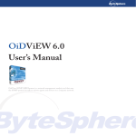
The following figure summarises the class-map logic flow:
Start
yes
yes
Also
match on other
things?
Get criteria by
ANDing together
ACL and other
match commands
no
Get criteria by
using ACL settings
Match
on ACL?
no
yes
Instead
match on other
things?
Get criteria by
ANDing together
other match
commands
Apply action from ACL
(permit, deny, send-to-mirror,
send-to-cpu, copy-to-cpu)
no
Match all
packets
Apply default action
(permit)
The basic procedure for using a class-map as a filter is:
1. Make an ACL both to match on MAC address and/or IP settings, and to specify the action
for QoS to take on traffic that matches the class-map.
You need an ACL to specify the action, unless the action is permit, even if you don't want
to match on MAC address or IP settings. In that case, make an ACL with the desired action
and with both source and destination address of any. For example, if you want to deny
traffic from one VLAN ID, you need an ACL with action of deny, and addresses of any.
Page 18 | AlliedWare Plus™ OS How To Note
Applying filters by using QoS class-maps
2. Create the class-map, as shown below.
3. Specify what the class-map will match on, as explained below. This involves:
attaching the ACL to the class-map
using other match commands to further limit what the traffic will match the class-map
(unless the ACL's match criteria were enough)
4. Apply the class-maps to a policy-map. See“Apply the class-maps to a policy-map” on
page 22.
5. Apply the policy-map to the ingress port or ports. See “Apply the policy-map to ports” on
page 22
Create a class-map
To create a class-map, enter global configuration mode and use the command:
awplus(config)#class-map <name>
This puts you into class-map configuration mode.
Specify what the class-map will match on
To do this, first attach the ACL to the class-map (unless you don't need an ACL). In class-map
configuration mode, use one of the commands:
class-map cmap1
match access-group <number>
or
class-map cmap1
match access-group <name>
Next, use other match commands to further limit which traffic will match the class-map
(unless the ACL's match criteria were enough). This means that you select the matching
traffic by using a combination of the ACL's settings and the QoS match commands. The ACL
and match commands are ANDed together to make the class-map's filtering rule. The
available match commands are:
match cos
match dscp
match ip-precedence
match eth-format protocol (or match protocol eth-format)
match tpid
match inner-cos
match inner-tpid
match inner-vlan
match mac-type
match tcp-flags
match vlan
Page 19 | AlliedWare Plus™ OS How To Note
Applying filters by using QoS class-maps
Most of these options are self-evident, but the following sections give more information
about "inner" options, TCP flags, and eth-format and protocol options.
Except for TCP flags, each class-map can only match on one instance of each match type. If
you enter multiple matches of the same type, the class-map uses the last match you specify.
If you need more than one filtering rule on the port, create class-maps for each other filter.
Match on "inner" keywords for nested VLANs
The match tpid, match inner-tpid, match inner-vlan, and match inner-cos
commands all apply to nested VLAN configuration. In this situation, packets arriving at the
core-facing port can contain two VLAN tags.
match tpid matches on the first Tag Protocol Identifier field in the packet.
match inner-tpid matches on the TPID in the second 802.1Q tag in the packet.
match inner-vlan matches on the tunnelled VLAN ID in the second 802.1Q tag in the
packet.
match inner-cos matches on the 802.1P field in the second tag in the packet.
The following table shows where in the packet the inner and outer tags are matched:
Outer VLAN parameters
Inner VLAN parameters
(normal)
Customer port
VLAN
1st tag
Core port
1st tag
2nd tag
Nested VLANs disabled
1st tag
2nd tag
Some important points to keep in mind while configuring the “inner” commands are:
When packets arrive at a customer port of a nested VLAN, the command match vlan
matches the VID of the nested VLAN that the port is a member of.
When packets arrive at a customer port of a nested VLAN, the “inner” commands match
the attributes of the first tag in the packets. This is because when the packet is forwarded
from the core port, that first tag becomes the inner tag. So, from the point of view of the
nested VLAN, the tag that is on the packet when it arrives into the customer port is the
inner tag.
When nested VLANs are disabled, and “inner” commands have been configured in classmaps, these parameters are applied as though all packets arriving at the switch were
double tagged. In other words, there is no attempt to make a distinction between
“customer” and “core” ports. So, if the packets arriving at the switch are not double
tagged, then the “inner” commands simply match on whatever data happens to be in the
packets at the position where an inner tag would have been.
Therefore, when you disable nested VLANs, you should also remove the match
commands that match on “inner” values.
When nested VLANs are in use, the commands match tpid and match cos cannot be
used in class-maps applied to customer ports.
If you attach class-map to a number of ports, they are all treated like core ports if at least
one of the ports is a core port.
Page 20 | AlliedWare Plus™ OS How To Note
Applying filters by using QoS class-maps
Match on TCP flag
Unlike other match commands, you can match on multiple TCP flags. The switch combines
the specified flags by ANDing them together. To specify the multiple flags, either make
multiple match tcp-flags commands or specify the flags in one command as a spaceseparated list.
Example
The following series of commands match on a packet that has all of ACK, SYN and FIN set:
awplus(config)#class-map tcp-flags
awplus(config-cmap)#match tcp-flags ack
awplus(config-cmap)#match tcp-flags syn
awplus(config-cmap)#match tcp-flags fin
So does the following single match command:
awplus(config)#class-map tcp-flags
awplus(config-cmap)#match tcp-flags ack syn fin
QoS only checks that the specified flags are set, not that the other flags are not set. The
following commands match on a packet that has both SYN and ACK set, as well as a packet
that has SYN but not ACK set:
awplus(config)#class-map tcp-flags
awplus(config-cmap)#match tcp-flags syn
To drop packets with SYN only, but not with ACK and SYN, you could use the following two
class-maps. Note that access-list 3000 is used to get a deny action. This example is explained
fully in "Blocking TCP sessions in one direction" on page 28.
awplus(config)#access-list 3000 deny tcp any any
awplus(config)#class-map ack-syn-flags
awplus(config-cmap)#match tcp-flags ack syn
awplus(config-cmap)#class-map syn-flags
awplus(config-cmap)#match tcp-flags syn
awplus(config-cmap)#match access-group 3000
awplus(config-cmap)#policy-map flags
awplus(config-pmap)#class ack-syn-flags
awplus(config-pmap-c)#class syn-flags
Match on eth-format and protocol
Ethernet format and protocol are specified together, as a pair. You can either specify the
command as:
match eth-format <keyword> protocol <keyword-or-number>
or
match protocol <keyword-or-number> eth-format <keyword>
The switch allows you to match on any of the Ethernet formats, as the following output
shows:
Page 21 | AlliedWare Plus™ OS How To Note
Applying filters by using QoS class-maps
awplus(config-cmap)#match eth-format ?
802dot2-tagged
802.2 Tagged Packets
802dot2-untagged
802.2 Untagged Packets
ethii-tagged
EthII Tagged Packets
ethii-untagged
EthII Untagged Packets
netwareraw-tagged
Netware Raw Tagged Packets
netwareraw-untagged Netware Raw Untagged Packets
snap-tagged
SNAP Tagged Packets
snap-untagged
SNAP Untagged Packets
Protocol options are also extremely flexible. You can identify common protocols by their
name, or you can identify any protocol by using its hexadecimal protocol number.
Apply the class-maps to a policy-map
To create a policy-map, enter global configuration mode and use the command:
awplus(config)#policy-map <name>
Then add the class-maps to the policy-map. Make sure you add them in the order in which
you want the switch to check them—see “The logic of the operation of the hardware filters”
on page 23. For each class-map, use the command:
awplus(config-pmap)#class <name>
Apply the policy-map to ports
To apply the policy-map to ports, enter interface mode for the ports you want to apply it to.
Use the commands:
awplus(config)#interface port1.0.11
awplus(config-if)#service-policy input <policy-name>
Page 22 | AlliedWare Plus™ OS How To Note
The logic of the operation of the hardware filters
The logic of the operation of the hardware filters
Filter operation follows the standard ACL logic: if a packet matches an ACL on the port, the
comparison process stops and the action attached to the ACL is performed. The switch
checks numbered ACLs in the order in which you attach them to the port. Within a
Named Hardware ACL, the entries are checked in sequence number order.
For example: to reject all multicast traffic except 236.5.8.213, make one ACL to permit that
address and another ACL to deny all multicast traffic. Then attach the permit ACL to the
port before attaching the deny ACL.
If a packet fails to match any of the port’s ACLs, then the switch moves to the next stage of
comparison. The next stage is matching against QoS class-maps, if they exist. If the packet
matches a QoS class-map, it is processed appropriately. If it does not match a class-map, it is
processed as normal. Therefore, ACLs do not end in an implicit deny action to drop nonmatching traffic. But, they also do not end in an implicit forward action that would bypass
other processing and forward non-matching traffic. The switch simply continues processing
non-matching traffic as normal.
Note:
ACLs match on packets that are destined for the switch itself (packets that would be
passed up to the switch's own CPU) in exactly the same way as they act on packets
destined to be forwarded directly to another external port by the switching chip.
Page 23 | AlliedWare Plus™ OS How To Note
Combining interface ACLs and QoS class-maps
Combining interface ACLs and QoS class-maps
The switch compares the packet with every interface ACL before it compares the packet
with any QoS class-maps. If the packet matches an interface ACL, the switch takes the action
specified by that ACL and stops the comparison process. If a packet matches both an
interface ACL and a QoS class-map, the packet is only matched against the interface ACL - it
bypasses the QoS process.
If the action on the interface ACL is deny or send-to-cpu, then this is not a problem,
because the packet was going to be discarded anyway. But, if the action on the interface ACL
is permit, copy-to-cpu, or copy-to-mirror, and the packet would also be matched by a
QoS class-map, then this is a problem. The packet won’t be matched by the QoS class-map,
so the switch won’t apply any intended QoS-based filtering, policing, queue redirection, and
so on to the packet. Instead the switch forwards the packet as if it belongs to the default
class-map.
For this reason, we only recommend combining interface ACLs and QoS class-map filtering if
all your interface ACLs result in traffic being dropped. For traffic that you want forwarded
with QoS control, use QoS class-maps for both the filtering and the QoS actions. Of course,
you can also use QoS class-maps to drop traffic.
Page 24 | AlliedWare Plus™ OS How To Note
Examples
Examples
Blocking all multicast traffic
This example uses an interface ACL with an action of deny.
Consider a situation where multiple clients are attached to the switch, with each client
attached to a different port. Each client has a specific service, which includes a set of allowed
traffic types.
The client on port 1.0.10 is using a service that does not allow any multicast packets to be
sent. To configure this:
1. Create an ACL to match and deny all packets with a multicast destination address. To do
this, enter global configuration mode and use the command:
awplus(config)#access-list 3100 deny ip any 224.0.0.0/4
2. Attach the ACL to port 1.0.10. To do this, use the commands:
awplus(config)#interface port1.0.10
awplus(config-if)#access-group 3100
3. Verify the configuration.
To see the ACL ID number and keywords, return to privileged exec mode and enter the
command:
awplus#show access-list
To see the ACLs that are attached to port 1.0.10, enter the command:
awplus#show interface port1.0.10 access-group
Blocking all multicast traffic except one address
This example uses two interface ACLs, one with an action of permit and one with an action
of deny.
Use this type of configuration when you want to discard a wide range of traffic, but you also
want to forward a subset of traffic within that range. For example, a situation where you
want to prevent the forwarding of multicast traffic in general, but wish to support an
application that needs to send packets to one particular multicast address (236.5.8.213 in this
example).
To configure this:
1. Create an ACL to match and permit packets with the multicast destination address
236.5.8.213. To do this, enter global configuration mode and use the command:
awplus(config)#access-list 3050 permit ip any 236.5.8.213/32
2. Create an ACL to match and deny all packets with a multicast destination address. To do
this, use the command:
awplus(config)#access-list 3100 deny ip any 224.0.0.0/4
Page 25 | AlliedWare Plus™ OS How To Note
Examples
3. Attach the ACLs to the port (for example, 1.0.10). You must first attach the permit ACL,
then the deny ACL. To do this, use the commands:
awplus(config)#interface port1.0.10
awplus(config-if)# access-group 3050
awplus(config-if)# access-group 3100
It is also possible to achieve the same filtering requirements with a Named Hardware ACL:
1. Create a named hardware ACL and then a sequential entry to match and permit packets
with the multicast destination address 236.5.8.213. To do this, enter global configuration
mode and use the commands:
(config)#access-list hardware mc_filter
(config-ip-hw-acl)#10 permit ip any 236.5.8.213/32
2. Create another sequential entry to match and deny all packets with a multicast destination
address. To do this, use the command:
(config-ip-hw-acl)#20 deny ip any 224.0.0.0/4
You can also verify the access-list:
#show access-list mc_filter
Hardware IP access list mc_filter
10 permit ip any 236.5.8.213/32
20 deny ip any 224.0.0.0/4
3. Attach the Named Hardware sequential ACLs to the port (for example, 1.0.7). To do this,
use the commands:
(config)#interface port1.0.7
(config-if)#access-group mc_filter
You can also verify the access-group is attached to the interface:
#show interface port1.0.7 access-group
Interface port1.0.7
access-group mc_filter
Mirroring HTTP and SMTP traffic
This example uses two interface ACLs with action copy-to-mirror.
Use this type of configuration when you want to mirror a subset of the incoming traffic on a
port, instead of mirroring all incoming traffic.
For example, you may want to capture the HTTP (TCP port 80) and SMTP (TCP port 25)
traffic coming to users who are connected to ports 1.0.1-1.0.2. To configure this:
1. Set port 1.0.20 as the mirror port. To do this, enter global configuration mode and use the
commands:
awplus(config)#interface port1.0.20
awplus(config-if)#mirror interface portx.y.z direction both
Page 26 | AlliedWare Plus™ OS How To Note
Examples
2. Create ACLs to match and mirror HTTP and SMTP traffic. To do this, return to global
configuration mode and use the commands:
awplus(config)#access-list 3100 copy-to-mirror tcp any any eq 25
awplus(config)#access-list 3200 copy-to-mirror tcp any any eq 80
3. Attach the ACLs to ports 1.0.1-1.0.2. To do this, use the commands:
awplus(config)#interface port1.0.1-1.0.2
awplus(config-if)# access-group 3100
awplus(config-if)# access-group 3200
Alternatively, you could do this using Named Hardware ACLs instead:
1. Set port 1.0.20 as the mirror port. To do this, enter global configuration mode and use the
commands:
(config)# interface port1.0.20
awplus(config-if)#mirror interface portx.y.z direction both
portx.y.z is another port, possibly unused, whose traffic will also have to be mirrored as
a minimum requirement to enabling mirroring on.
2. Create Named Sequential Hardware ACLs to match and mirror HTTP and SMTP traffic.
To do this, return to global configuration mode and use the commands:
(config)# access-list hardware mirror_example
(config-ip-hw-acl)# 10 copy-to-mirror tcp any any eq 25
(config-ip-hw-acl)# 20 copy-to-mirror tcp any any eq 80
3. Attach the Hardware Sequential ACLs to ports 1.0.13-1.0.14. To do this, use the
commands:
(config)#interface port1.0.13-1.0.14
(config-if)#access-group mirror_example
Mirroring ARP packets
This example uses a QoS class-map. Use this type of configuration when you want to mirror
a subset of the incoming traffic on a port, and you need to use QoS match commands to
select the mirrored traffic.
For example, you may want to capture ARP packets that arrive at port 1.0.10. To configure
this:
1. Set port 1.0.20 as the mirror port. To do this, enter global configuration mode and use the
commands:
awplus(config)#interface port1.0.20
awplus(config-if)#mirror interface portx.y.z direction both
portx.y.z is another port, possibly unused, whose traffic will also have to be mirrored as
a minimum requirement to enabling mirroring on.
2. Create an ACL with an action of copy-to-mirror. This ACL will only be used to set the
action taken on the ARP traffic, not to select the traffic, so it needs to match all IP traffic.
To do this, return to global configuration mode and use the commands:
awplus(config)#access-list 3400 copy-to-mirror ip any any
Page 27 | AlliedWare Plus™ OS How To Note
Examples
3. Create a class-map that matches on ARP traffic and uses the ACL. To do this, use the
commands:
awplus(config)#class-map mirror-arp
awplus(config-cmap)#match protocol arp eth-format ethii-untagged
awplus(config-cmap)#match access-group 3400
4. Create a policy-map and add the class-map to it. To do this, use the commands:
awplus(config-cmap)#policy-map mirror-arp
awplus(config-pmap)#class mirror-arp
5. Apply the policy-map to port 1.0.10. To do this, use the commands:
awplus(config-pmap-c)#interface port1.0.10
awplus(config-if)#service-policy input mirror-arp
Blocking TCP sessions in one direction
This example uses two QoS class-maps.
Administrators often want to block the establishment of TCP sessions in one direction, but
allow TCP sessions to be established in the opposite direction. To do this, you must prevent
the very first packet of an outgoing TCP session from being forwarded, but still allow any
packets that reply to the initiation of an incoming TCP session to be forwarded.
The very first packet of a TCP session has the SYN flag set, and no other flags. The reply to
that packet has the SYN and ACK flags set, and no other flags. So, to block TCP sessions
from being established in one direction, but not the other direction, you must block packets
that have only the SYN flag set, but allow packets that have both the SYN and ACK flags set.
Note:
Example
As previously described, class-maps with multiple match statements defined have
match statements that AND together. If an ACL match statement is included, the
ACL's defined action, for example drop, is applied to each matching frame. In
contrast, each packet inspected by a policy map obeys the first matching class-map if
multiple class-maps have been applied to the policy map. This is similar to an OR
statement, where only the first matching criteria takes effect.
In summary: match criteria within a class map are combined by AND; classes with a
policy map are combined by OR.
To configure this on port 1.0.10:
1. Create an ACL with an action of deny. This ACL is only used to set the action taken on
packets with only the SYN flag set, not to select the traffic, so it needs to match all IP
traffic. To do this, enter global configuration mode and use the command:
awplus(config)#access-list 3000 deny tcp any any
2. Create a class-map that matches on packets that have both the SYN and ACK flags set. To
do this, use the commands:
awplus(config)#class-map ack-syn-flags
awplus(config-cmap)#match tcp-flags ack syn
You want to permit this traffic, so you do not need to make an ACL to specify an action.
Page 28 | AlliedWare Plus™ OS How To Note
Examples
3. Create a second class-map that matches on packets that have only the SYN flag set. Use
the ACL to give this class-map an action of drop. To do this, use the commands:
awplus(config-cmap)#class-map syn-flags
awplus(config-cmap)#match tcp-flags syn
awplus(config-cmap)#match access-group 3000
4. Create a policy-map and add both class-maps to it. Add the class-map that matches both
flags first, followed by the class-map that drops packets with only the SYN flag. To do this,
use the commands:
awplus(config-cmap)#policy-map flags
awplus(config-pmap)#class ack-syn-flags
awplus(config-pmap-c)#class syn-flags
5. Apply the policy-map to port 1.0.10. To do this, use the commands:
awplus(config-pmap-c)#interface port1.0.10
awplus(config-if)#service-policy input flags
Combining Named Hardware ACL entries to match on MAC, VLAN,
IP and TCP fields
A wide variety of parameters can be combined in a single named ACL.
1. Create a named hardware ACL. To do this, enter global configuration mode and use the
command:
(config)#access-list hardware combined_entries
2. Create a sequential entry to match and deny all packets with a certain MAC address. To
do this, use the command:
(config-ip-hw-acl)#10 deny mac 1234.5678.9abc 0000.0000.0000 any
3. Create a sequential entry to match and deny all packets of a certain VLAN. To do this, use
the command:
(config-ip-hw-acl)# 20 deny mac any any vlan 4
4. Create a sequential entry to match and deny any ip packet destined for the subnet
172.28.0.0 /16. To do this, use the command:
(config-ip-hw-acl)#30 deny ip any 172.28.0.0 0.0.255.255
5. Create a sequential entry to match and deny any TCP packet destined for the subnet
172.30.0.0 /16. To do this, use the command:
(config-ip-hw-acl)#40 deny tcp any 172.30.0.0 0.0.255.255
6. You can also verify the access-list:
#show access-list combined_entries
Hardware IP access list combined_entries
10 deny mac 1234.5678.9abc 0000.0000.0000 any
20 deny mac any any vlan 4
30 deny ip any 172.28.0.0/16
40 deny tcp any 172.30.0.0/16
Page 29 | AlliedWare Plus™ OS How To Note
Examples
7. Attach the Named Sequential Hardware ACLs to the port (for example, 1.0.9). To do this,
use the commands:
(config)#int port1.0.9
(config-if)#access-group combined_entries
8. You can also verify the access-group is attached to the interface:
#show interface port1.0.9 access-group
Interface port1.0.9
access-group combined_entries
Page 30 | AlliedWare Plus™ OS How To Note
How many filters can you create?
How many filters can you create?
The total number of filters that you can create is not a defined number, but depends on
which fields the various filters are matching on. So, to figure out whether the set of filters you
are creating might exceed the limit, it is necessary to understand the way in which the filters
operate in the switch hardware.
There are two items within the switch hardware that set limits on the number of filters you
can create. These are the filter rule tables and the profile (mask).
Filters share the same filter rule tables and mask whether they are made by applying ACLs
globally or directly to ports, or are made through QoS class-maps.
1. The filter rule tables
Switches have multiple switch chips, each referred to below as 'instance':
Ports 1-12 are in the first switch chip (instance)
ports 13 -24 are in the next switch chip (instance)
And so on.
Each XEM is also a separate instance. There is a filter rule table per silicon instance.
The filter rule tables contain a limited list of filter rules. Each table has a limit of 1024 entries
per silicon instance. This limit can be lifted to 2048 entries per instance if you use a special
ipv4-only silicon mode configured with "platform routingratio ipv4only".
At least one entry gets made when:
You apply a Hardware ACL to a port with the access-group command
You apply a Hardware ACL globally with the access-group command
You apply a QoS class-map to a port by applying its policy-map to a port, with the servicepolicy input command. For each class-map, its ACL and any match commands are
ANDed together to make a single filter entry.
On x900 and SwitchBlade x908 switches, you can assign each silicon filtering slot either
globally or to one individual port. So in a multi-port application, a Hardware ACL assigned to
ports 1.0.1-1.0.5 and also to port 1.0.8, consumes 6 silicon filtering table entries.
To expand on the above points, silicon filter table entry consumption is as follows:
Numbered Hardware ACLs
a
Each time you apply a Numbered Hardware ACL to a port it uses up at least one of
the table entries in the switch instance that port belongs to. By extension, if you apply
the ACL to multiple ports, then a new copy of the table entry is made on the
appropriate switch instance, for each new port interface.
b Each time you apply a Numbered Hardware ACL globally to the switch it uses up at
least one of the table entries in each switch instance
c
If an x900 or SwitchBlade x908 switch has a configuration that applies some Numbered
Hardware ACLs globally and any Hardware ACLs to certain ports, then this
necessitates copies of the global ACLs for ports with other ACLs specifically applied
Page 31 | AlliedWare Plus™ OS How To Note
How many filters can you create?
on them. In this mixed-configuration case, the global ACLs actually consume multiple
silicon filter table entries.
Named Sequential Hardware ACLs
a
Each time you apply a Named Sequential Hardware ACL to a port, the number of table
entries used up in the switch instance that port belongs to is at least equal to the
number of sequential entries within that ACL. By extension, if you apply the ACL to
multiple ports, then the table entries are copied for each new port interface.
b Each time you apply a Named Sequential Hardware ACL globally, the number of table
entries used up in each switch instance is at least equal to the number of sequential
entries within that ACL.
c
Note:
Example
If an x900 switch has a configuration that applies some Named Sequential Hardware
ACLs globally, and any Hardware ACLs to certain ports, then this necessitates copies
of the global ACLs for ports with other ACLs specifically applied on them. In this
mixed-configuration case, the global ACLs will actually consume multiple silicon filter
table entries.
Generally just one silicon filter table entry is consumed for each ACL, but several
factors (such as a UDP port range defined) can cause the number of silicon table
entries consumed (i.e.: table entries) by an ACL to increase. See "Factors that cause
multiple silicon filter table entry consumption" on page 34.
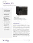
Point c listed above can be illustrated as follows. We start with ACL1 applied globally:
Page 32 | AlliedWare Plus™ OS How To Note
How many filters can you create?
Hardware Filter Table
Packets arriving on all ports are sent to this single
entry:
Global ACL1
Add a local ACL to port 2 (implicitly 'after' the global ACL reference):
Packets arriving on all ports, except port 2 pass
through this entry:
Packets arriving on port 2 are passed through these
two entries:
Hardware Filter Table
{
Global ACL1
Copy for port 2: ACL1
Local ACL for port 2
You now have 3 distinct ACLs in the hardware: GlobalACL1, "Copy for port 2: ACL1", and
"Local ACL for port 2". This is because any port that has a different set of filters must have its
own completely separate set of table entries.
Page 33 | AlliedWare Plus™ OS How To Note
How many filters can you create?
The allocation of silicon filter table entries
Conceptually, the allocation of silicon filter table entries occurs this way:
Table for Silicon Instance 1
Silicon filter Purpose (ACL rule,
table entry QoS class map or
number
protocol).
Silicon filter table entry Comment
applied either globally, or
to a particular port.
1
ACL rule 1
Global application
2
ACL rule 2
Port1.0.3
3
ACL rule 1
Copy of global filter for
port1.0.3
If a globally applied ACL exists,
then any port which has a
directly applied ACL will need
its own copy of the global ACL
4
ACL rule 2
Port1.0.4
ACL rule 2 was applied to two
specific ports, so it uses two
silicon filter table entries
5
ACL rule 1
Copy of global filter for
port1.0.4
If a globally applied ACL exists,
then any port which has a
directly applied ACL will need
its own copy of the global ACL
6
QoS class-map rule
Port1.0.8
7
ACL rule 1
Copy of global filter for
port1.0.8
8
...
...
A rule can be applied globally or
to one port per entry. If applied
globally, an entry is taken in each
instance of silicon.
If a globally applied ACL exists,
then any port which has a
directly applied QOS Class-Map
will need its own copy of the
global ACL
Also, the protocols that use filters (CPU protection and EPSR) create one entry per port.
Factors that cause multiple silicon filter table entry consumption
a
As illustrated above, a configuration that applies some Hardware ACLs globally and
some Hardware ACLs to certain ports necessitates copies of the global ACLs to ports
with other ACLs specifically applied on them.
b If a QoS Class-Map is applied to a port on the switch, it also consumes at least one
filter table entry. In a similar way to above, if the switch also has globally applied
Hardware ACLs - those global ACLs also need to be copied to each port that has a
QoS Class-Map applied.
c
If you specify a TCP or UDP port range, this may use multiple filter entries. The switch
converts the range to a series of single TCP/UDP port numbers plus masks. It uses as
few entries as possible to cover the range.
Page 34 | AlliedWare Plus™ OS How To Note
How many filters can you create?
About port range table entry consumption:
A single filter table entry for an L4 port range can only cover a range of port numbers that
fall within a single binary mask. To filter on a range of port numbers that do not fall within a
single binary mask, the filter uses multiple filter table entries. The number of entries
consumed depends on the range of port numbers. Now, let’s take a look at some examples
of how to calculate the number of entries used by a range of port numbers.
Applying an L4 mask to an UDP/TCP port allows you to identify the constant and variable
parts of a range of port numbers. The constant bits are represented by the 1s in the mask,
and the variable bits are represented by the 0s. Performing a bitwise logical AND operation
between the port number and the L4 mask results in the first port number of the range.
Note:
The logical AND operation compares 2 bits and if they are both "1", then the result
is "1", otherwise, the result is "0".
Let's look at an example.
Example:
ports 20002003
Let's say you want to have a UDP port range of 2000-2003. The range of binary numbers to
use are:
2000 = 00010011 10001100
2001 = 00010011 10001101
2002 = 00010011 10001110
2003 = 00010011 10001111
The changed bits from 2000-2003 are in bold. You must now write an L4 mask which will
meet these requirements. The easiest way to do this is to set the changed bits (between 2000
and 2003) in the mask to 0. In our example, they are the last 2 bits. So our mask should be:
L4 Mask = 11111111 11111100
Then convert the binary number of 11111111 11111100 to hex, which ends in FF FC.
In terms of table entry consumption, this range of port numbers can be expressed in one
silicon entry, because one mask expresses the whole desired range of port numbers.
However, in some cases more table entries are consumed because the desired range is not
contained in a single mask value.
Example
Choose a starting port number in which the last 2 bits are 0, and also select 4 as the number
of the ports in order to simplify the example.
Note:
If the beginning port is an odd number (last bit 1), then in order to cover a range of
ports, you will need an extra silicon table entry.
You can easily calculate the total number of ports in a mask by using the formula 2^x (where
x is the number of the 0s at the end of the mask). For example, a mask of
1111111111111000 will cover a range of 2^3 = 8 ports.
Page 35 | AlliedWare Plus™ OS How To Note
How many filters can you create?
Divide the total number of the ports you want to cover into a sum of powers of 2. For
example, a range of 77 ports could be divided into:
64 + 8 + 4 + 1 =77
This shows us that a group of 77 ports could be covered by a minimum of 4 table entries.
To see more examples, refer to: How To Configure Hardware Filters on AT-9900, x900-48,
and x900-24 Series Switches: http://www.alliedtelesis.com/media/fount/
how_to_note_alliedware/howto_config_hw_filters_x900.pdf
How many table entries have been taken?
You can confirm how many table entries have been consumed in the silicon with the
command:
#show platform classifier statistics utilization brief
[Instance 0]
[ port1.0.1-1.0.12]
Number of PCE Entries:
Used / Total
-------------------------------Global ACL
4
ACL
1
QoS
0
Total
5 / 2048 ( 0%)
Profiles:
Legend of Offset Type) 1:Ether 2:IP 3:TCP/UDP
Packet Type
Offset Type
Used / Total
------------- 0------8------15 -----------TCP (IPv4)
2222233000000000
7 / 16
UDP (IPv4)
2222233000000000
7 / 16
IPv4 fragment 2222233000000000
7 / 16
IPv4 other
2222233000000000
7 / 16
Ethernet
0000000000000000
0 / 16
IPv6
0000000000000000
0 / 16
The number of silicon table entries quoted is actually available on each instance of silicon in
your device. The example above is taken from a 12 port switch, so only one instance is
shown.
2. The profile (mask)
The other item that puts a limit on the number of ACLs you can create is called the profile.
Conceptually, this is a 16-byte mask that decides which set of bytes should be extracted from
a packet as it enters the filtering process, to be compared against all the interface ACLs and
the QoS class-maps. All filters for a given packet type share a single mask.
In effect, some bytes within the 16-byte mask are filled when any unique field type is used
somewhere in a filter. This means that if two ACLs cite the same field types, then the second
ACL does not add to how much of the 16-byte mask is filled, because it introduces no unique
Page 36 | AlliedWare Plus™ OS How To Note
How many filters can you create?
field types to filter on. However, more bytes are filled within the mask when a new ACL is
defined that introduces a unique field type.
Examples of the number of bytes used by different field types are:
source MAC address—6 bytes
destination MAC address—6 bytes
Protocol type—2 bytes
Ethernet format—2 bytes
VLAN ID—2 bytes
IP protocol type (TCP, UDP, etc)—1 byte
source IP address—4 bytes
destination IP address—4 bytes
TCP port number—2 bytes
UDP port number—2 bytes
DSCP—1 byte
Example
1. If you make an ACL that matches on destination IP address and source TCP port, this adds
7 bytes to the mask:
1 byte for the IP protocol field (to indicate TCP)
4 bytes for the destination IP address
2 bytes for the source TCP port number.
IP Prot
Dest IP
Dest IP
Dest IP
Dest IP
Src TCP Src TCP
Port
Port
2. If you next make an ACL that matches on source MAC address, this adds 6 more bytes to
the mask:
Src
Src
Src
Src
Src
Src
IP
MAC MAC MAC MAC MAC MAC Prot
Dest Dest Dest Dest Src
IP
IP
IP
IP
TCP
Port
Src
TCP
Port
3. If you next make a QoS class-map that matches on destination IP address (4 bytes) and
DSCP (1 byte), this adds 1 more byte to the mask, for the DSCP. It does not add 4 more
bytes for the destination IP address because the switch already matches on that field:
Src
Src
Src
Src
Src
Src
IP
MAC MAC MAC MAC MAC MAC Prot
Dest Dest Dest Dest Src
IP
IP
IP
IP
TCP
Port
Src
TCP
Port
DSCP
4. If you next make an ACL that matches on source IP address and source TCP port, then
that does not change the mask, because the switch already matches on those fields.
5. If you next make an ACL that matches on source UDP port, this also does not add any
length to the mask, because it shares the same 2 bytes as the source TCP port. However,
Page 37 | AlliedWare Plus™ OS How To Note
How many filters can you create?
if you next make an ACL that matches on destination TCP or UDP port, that uses another
2 bytes.
Src
Src
Src
Src
Src
Src
IP
MAC MAC MAC MAC MAC MAC Prot
Dest Dest Dest Dest Src
IP
IP
IP
IP
TCP
Port
Src
TCP
Port
Dest Dest DSCP
Port Port
Are there enough bytes for your set of filters?
Of course, the mask cannot increase without limit—it has a maximum size of 16 bytes.
When it reaches the 16-byte limit, you may not create more ACLs or QoS match commands
that would cause the mask to increase in size. The switch can still accept ACLs or QoS match
commands that use fields that have already been included in the mask.
There is no particular number of ACLs or QoS match commands that will cause the mask to
reach its 16-byte limit—it could happen after a few ACLs, or you might be able to create
hundreds of ACLs and QoS match commands without the mask reaching its limit.
So to determine whether you will have enough filter length, look at the fields you want to
filter, determine the number of bytes for each field, and sum up the total number of
bytes. If that number is less than 16, there is enough filter length. Don’t forget to count TCP
and UDP source port as a single field, and likewise to count TCP and UDP destination port
as a single field.
Okay length
example
This set of ACLs would work:
source MAC address
source UDP port
destination IP address + destination TCP port
The total number of bytes for the switch to check in a packet would be:
source MAC address + IP protocol type + source TCP/UDP port +
destination IP address + destination TCP/UDP port =
6 + 1 + 2 + 4 + 2 = 15 bytes
Too long
example
This set of ACLs would not work:
source MAC address
destination MAC address
destination IP address + destination TCP port
The total number of bytes for the switch to check in a packet would be:
source MAC address + destination MAC address + IP protocol type +
destination IP address + destination TCP/UDP port =
6 + 6 + 1 + 4 + 2 = 19 bytes
Page 38 | AlliedWare Plus™ OS How To Note
How many filters can you create?
Some other features also use filters, so use some of the length
The following features use filters, and therefore use up some of the available profile length
and filter entries:
CPU
protection
CPU protection is enabled by default. It controls the rate at which packets reach the CPU,
and uses filters to ensure that ARP and unregistered multicast packets get prioritised
appropriately.
It matches on:
Ethertype—2 bytes to check for ARP, and
VLAN tagging—2 bytes to check for tagged ARPs, and
Destination MAC address—6 bytes to check for unregistered multicasts (01-00-5E-00-00xx), or
Destination IP address—4 bytes to check for unregistered multicasts (224.0.0.x).
If you configure a filter that uses destination IP address, CPU protection automatically
changes from using the destination MAC address to the destination IP address (as long as no
other filter already uses the destination MAC address). This minimises the impact CPU
protection has on the number of filters available. However, it still uses 8-10 bytes of width.
If you are sure your network will not have an excessive rate of broadcast and multicast traffic,
you can turn off CPU protection by using the command no platform cpuprotection.
Page 39 | AlliedWare Plus™ OS How To Note
Reference section
Recommended documents that are useful in understanding silicon ACL slot consumption and
limits:
http://www.alliedtelesis.com/media/fount/how_to_note_alliedware_plus/
howto_aw_plus__hardware_filtering_REV_C.pdf
Pending: Separate Tips and Tricks Note on x600 Slot Consumption Information
USA Headquarters | 19800 North Creek Parkway | Suite 100 | Bothell | WA 98011 | USA | T: +1 800 424 4284 | F: +1 425 481 3895
European Headquarters | Via Motta 24 | 6830 Chiasso | Switzerland | T: +41 91 69769.00 | F: +41 91 69769.11
Asia-Pacific Headquarters | 11 Tai Seng Link | Singapore | 534182 | T: +65 6383 3832 | F: +65 6383 3830
www.alliedtelesis.com
© 2010 Allied Telesis, Inc. All rights reserved. Information in this document is subject to change without notice. Allied Telesis is a trademark or registered trademark of Allied Telesis, Inc. in the United States and other countries.
All company names, logos, and product designs that are trademarks or registered trademarks are the property of their respective owners.
C613-16119-00 REV D