1
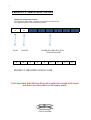
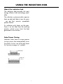
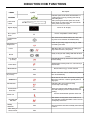
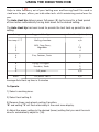
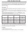
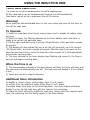
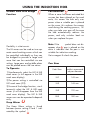
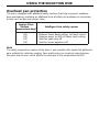
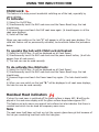
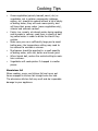
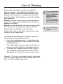
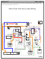
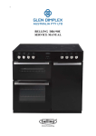
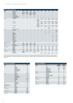
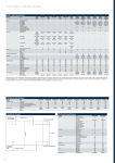
1
BELLING PBi 60 AU Mk2
SERVICE MANUAL
2
INDEX
PRODUCT IDENTIFICATION
PAGE
APPLIANCE RATING PLATE .............................................................
3
USER GUIDE AND INSTALLATION HANDBOOK
USER GUIDE..........................................................................................
INSTALLATION INSTRUCTIONS.......................................................
TECHNICAL DATA...............................................................................
CONTACT DETAILS .............................................................................
PART LIST PBI 60 AU MK 2.................................................................
WIRING DIAGRAM..............................................................................
4-27
28-33
34-34
35-35
36-36
37-37
REPAIR AND MAINTAINANCE
DISASSEMBLY PROCEDURES..........................................................
COMPONANT REMOVAL..................................................................
FAULTFINDING GUIDES...................................................................
INDUCTION PRESENTATION...........................................................
THIS MANUAL COVERS THE FOLLOWING MODELS :BELLING PBi 60 AU MK 2
38-40
41-45
46-47
48-59
3
PRODUCT IDENTIFICATION
Appliance rating plate location
The appliance rating plate is located on the right-hand side of the
front frame and also on the rear service panel
9
10
YEAR
4
1
8
MONTH
4
4
3
2
8
NUMBER OF PRODUCTION
FOR THE MONTH
4
4
4
0
0
2
8
PRODUCT IDENTIFICATION CODE
It is important that during all service calls the model and serial
numbers are recorded on all paper work.
Users Guide
& Installation
Handbook
Belling
Built in Induction Hob PBi60 AU
Contents
Warranty . . . . . . . . . . . . . . . . . . . . . . . . . . . . . . . . . . . . . . . . . . . . . . . . . . . .
Before using your appliance . . . . . . . . . . . . . . . . . . . . . . . . . . . . . . . . . . . . . . . . . . . .
Safety. . . . . . . . . . . . . . . . . . . . . . . . . . . . . . . . . . . . . . . . . . . . . . . . . . . . . . . . . . . .
Safety and induction . . . . . . . . . . . . . . . . . . . . . . . . . . . . . . . . . . . . . . . . . . . . . . . . .
Using the induction hob . . . . . . . . . . . . . . . . . . . . . . . . . . . . . . . . . . . . . . . . . . . . . . .
What The Symbols Mean . . . . . . . . . . . . . . . . . . . . . . . . . . . . . . . . . . . . . . . . . . . . . .
Using The Induction Hob . . . . . . . . . . . . . . . . . . . . . . . . . . . . . . . . . . . . . . . . . . . . . .
Cookware for Induction Hobs . . . . . . . . . . . . . . . . . . . . . . . . . . . . . . . . . . . . . . . .
Care of Pans . . . . . . . . . . . . . . . . . . . . . . . . . . . . . . . . . . . . . . . . . . . . . . . . . . . . . .
Cooking on Induction Hobs . . . . . . . . . . . . . . . . . . . . . . . . . . . . . . . . . . . . . . . . . . . .
Cooking tips . . . . . . . . . . . . . . . . . . . . . . . . . . . . . . . . . . . . . . . . . . . . . . . . . . . .
Care & Cleaning. . . . . . . . . . . . . . . . . . . . . . . . . . . . . . . . . . . . . . . . . . . . . . . . . . . .
Troubleshooting . . . . . . . . . . . . . . . . . . . . . . . . . . . . . . . . . . . . . . . . . . . . . . . . . . . .
Installation . . . . . . . . . . . . . . . . . . . . . . . . . . . . . . . . . . . . . . . . . . . . . . . . . . . . . . .
Technical Data . . . . . . . . . . . . . . . . . . . . . . . . . . . . . . . . . . . . . . . . . . . . . . . . . .
OUR WARRANTY
Should you need it . . . .
Inside the paperwork which has come with this appliance, there is a leaflet and card
explaining the terms of our extended warranty and guarantee. In order to apply for our
five year guarantee, simply fill in the details on the card and post it off, this will register
your appliance.
Should you wish to take out extended warranty, please fill in the details on the leaflet
and post this off to:
Glen Dimplex Australia
Unit 2, 205 Abbotts Road
Dandenong South
Victoria 3175
Australia
Ph: 1300 556 816
Fx: 1800 058 900
Glen Dimplex New Zealand Pty
38 Harris Road, East Tamaki
Auckland
New Zealand
Ph: 09 274 8265
Fx: 09 274 8472
If your appliance is covered by the warranty and guarantee, you will not be billed for
work undertaken should your appliance be faulty, terms and conditions do apply, so
please read through the literature carefully.
Please ensure that you have available your appliances model number and serial
number, there is a space at the back of this book for recording that information.
Before Using Your Hob
Thank you for purchasing a new Belling Induction
Hob. Its stylish and practical design will enhance your
kitchen and make cooking a pleasure. Even if you
have used an induction hob before, it is important that
you read these instructions thoroughly before starting
to cook, paying particular attention to the installation
and safety instructions.
If you have any problems with any aspect of your
Belling hob, please check through these instructions
thoroughly to make sure that you have not missed
anything. If you still need help, then please contact us
using the customer care centre number at the back of
this book.
!
Before using this appliance please make sure that
you have removed all packaging and wrapping.
Also remove stickers & film from the ceramic glass.
!
Although every care has been taken to ensure this
appliance has no burrs, or sharp edges, we
recommend that you wear protective gloves when
installing and moving this appliance.
This will prevent any injury.
Our policy is one of constant development and
improvement. Strict accuracy of illustrations and
specifications cannot be guaranteed. Modification
to design and material may be necessary
subsequent to publication.
!
Always use a registered installer for this appliance.
WARNING! For your own safety, make sure that
th ese in struc ti ons on ins tallat ion, use and
maintenance are followed.
Environmental protection:
Glen Dimplex Home Appliance brands are
committed to protecting the environment and operates and Environmental Management System which
complies with BS EN ISO 14001.
All packaging with this appliance is recyclable and
environmentally friendly.
Please recycle whenever possible - contact your
local authority for your nearest recycling centre.
This appliance is for
use in a domestic
kitchen only, it is not
designed, or intended, for commercial
use.
i
Please keep these
instructions in a safe
place.
Should you sell or
pass on the appliance, please give the
new owner this
handbook.
Safety
Keep children away from the vicinity of the hob
when you are cooking.
• Use pans with a flat base which are stable in use,
and avoid using any old misshapen pans or any pan
which is unstable when placed on a flat surface.
• Never leave fat or oil unattended on an active cook
zone. Don’t leave pans on the hob when you are
not around - remove them or turn the cook zones
off (even if only for a moment)
• This appliance is not intended for use by persons
(including children) with reduced physical, sensory
or mental capabilities, or lack of experience and
knowledge, unless they have been given supervision
or instruction concerning use of the appliance by a
person responsible for their safety.
• Children should be supervised to ensure that they
do not play with the appliance
• Keep all flammable materials away from the hob.
Ensure electrical leads do not trail over or go near
the hob.
• Do not place aluminium foil or plastic utensils on hot
surfaces.
• Turn pan handles to a safe position, so they are out
of reach of children, not overhanging the appliance
and cannot be caught accidentally.
• Commercial simmering aids should not be used as
they create excessive temperatures that can damage the surface and may cause a hazard.
• Caution: Do not use the hob if the glass is cracked,
as electrical parts are directly beneath. To avoid the
possibility of electric shock, turn off the electricity
supply to the hob at the socket and arrange a
Service call.
WARNING: If you use a griddle plate, ensure that
it is completely cool before attempting to lift it from
the hob as residual heat may cause burns. Always
use oven gloves to protect your hands.
Do not allow yourself to be distracted whilst cooking.
When you have finished cooking check that all controls are in the off position.
WARNING:- this appliance is unsuitable for use in a marine enviroment.
WARNING:- servicing should be carried out only by authorised personnel.
Safety Advice
Smoke alarm - buy a smoke alarm fitted with a ‘hush
button’ which can silence the alarm instantly should it
activate accidentally & does not necessitate the removal
of the battery (except to change for a new one).
Fire Blanket - consider having a fire blanket in your
kitchen, mounted on the wall where you can get to it
easily & quickly.
Deep-fat Frying - never fill a chip pan (or other deepfat fryer) more than one-third full of oil. If you do have
a chip pan fire:
1) call emergency services immediately
2) never move the pan
3) turn off the heat but only if it is safe do so
4) never use water on a chip pan fire as this will create
a fireball.
Kitchen Fire - if you have a fire in the kitchen, do not
take risks - get everybody out of the house & call 999.
If a pan catches fire:
1) do not move it - it is likely to be very hot
2) turn off the heat but only if safe to do so & never
lean over a pan to reach the controls
3) if you have a fire blanket, put it over the pan
4) do not use a fire extinguisher on a pan of oil - the
force of the extinguisher can spread the fire
5) if you have managed to extinguish the fire, allow the
pan to cool completely.
Electrical Fire - if you have an electrical fire in the
kitchen, do not take risks - get everybody out of the
house & call emergency services immediately
1) pull the plug out or switch off the power at the fuse
box - this may be enough to extinguish the fire immediately
2) smother the fire with a fire blanket or use a dry powder or carbon dioxide extinguisher
30 remember: never use water on an electrical fire.
Safety & Induction
Detection of an object or a pan on the heating
zone
A small object - such as a fork, a spoon or even a ring
- placed on a hob cooking zone on its own is not
detected as a pan.
The security system acts in the same way when it
detects a pan which is not suitable for use on an
induction hob.
If you are fitted with a pacemaker or an active
implant
The functions of the hob comply with the applicable
standards on electromagnetic interference
Your induction cooking hob thus complies fully with
the statutory requirements (Directive 89/336/EEC). It
is designed to not interfere with the functioning of
other electrical equipment as long as these also comply
with the same regulations.
Your induction hob generates magnetic fields in its
immediate vicinity.
So that there is no interference between your cooking
hob and a pacemaker, the pacemaker must be
designed in compliance with the appropriate regulations.
In this respect we can only guarantee the compliance
of our own product. You can ask the manufacturer or
your doctor about the compliance or any incompatibilities of your pacemaker.
USING THE INDUCTION HOB
About the induction hob
The induction hob provides the most
energy efficeint hob technology available.
The induction system provides superior
heat up and cool down times for pans
- you get fast, precise, repeatable
power control.
As induction only heats up the pan,
there is no lost heat from the cooking
process, which in turn, limits the heat
generated in the kitchen.
Auto Power Tuning
Induction hobs have a unique power
tuning systems that automatically tunes
the power to the size of the pan base
this ensures energy isn’t wasted.
Small pan
Large pan
-
USING THE INDUCTION HOB
Cookware for induction hobs
Cookware for inductio n cooking
zones must be made of metal and
have magnetic properties. The base
must also be the correct diameter.
Suitable Cookware for Induction Hobs
Unsuitable Cookware
Enameled steel pots with a thick base
Pots made of copper,
Cast Iron pots with an enameled base
stainless steel, aluminium,
oven-proof glass, wood
Pots made of multilayer stainless steel,
rustproof ferrite steel or aluminium with
a special base
Pans marked for use with induction
How to establish the suitability
of a pan
Check your pans with a magnet. If it
sticks and it’s the correct diameter, it’s
suitable for use with induction. Also
with pans that bear the symbol for suitability for cooking with induction.
Note - when using certain pans, you
may get various noises from the pans.
This is due to the design of the pans
and does not effect the performance or
safety of the hob.
ceramic and terracotta
.
INDUCTION HOB FUNCTIONS
.
PBI60 mk2 Induction Hob
Feature
Description
Symbol
Eco Power
Induction power is the most efficient means of
cooking food on a hob, providing fast heat up
and boiling times
Power slide
control
Slide your finger down the stylish & accurate
Power Slider or simply touch the control at the
exact power level you require
Digital display
No. of power
levels
Secret ʻtil “lit” display
Precise & repeatable control settings
11
Central On/Off
Switch
The central on/off switch enables all of the cooking zones to be switched off simultaneously
Keep Warm/Low
Temperature
Holds the pan temp. at approx. 65 deg. C - ideal
for melting chocolate.
With this button you can pause all cooking settings with one touch (cuts power)
Pause
Easily recall your hob settings with this function.
Recall
Auto Heat Up
(4 zones)
Automatically heats up & then turns down power to
a lower setting.
Power Boost
Temporarily boost the power to a cook zone by a
massive 60%
Minute Minder
Timer AutoSwitch
off (4 zones)
Need to time an egg - use this function
Yes
All four cook zones can be simultaneously timed to
turn off automatically.
Yes
Allows the LH cook zones to be linked creating one
large oval cook zone - ideal for griddle plates &
large pans.
Griddle Zone
Indicates if the correct pans are being
used & helps save energy.
Pan Detection
Overheat Pan
Detection
The hob is equipped with additional safety systems which help to prevent cookware from overheating.
Yes
Prevents unintentional operation of the hob
Child Lock
This feature not only warns of hot surfaces but
also indicates residual heat which can be used as
a temporary warm zone.
Residual Heat
Indicators
Holiday
Shutdown
Flush fitting or
surface mount
Yes
Rest assured this hob will eventually turn itself off
if left on.
Yes
. 9
.
USING THE INDUCTION HOB
.
Touch Controls
Touch controls
The touch controls for your induction have been designed to provide you with finger
tip control of your hob, providing accurate and repeatable power settings for cooking
and an easy clean surface that can be easily wiped over. When a cook zone is activated the power setting is displayed for each zone individually,
Using the Touch Controls
Using the Touch Controls
The cook zone and timer displays function as the touch controls, To select a cook
zone or the timer, simply touch the display area, use the flat of your finger, not the
tip, The controls respond to touch, so you don’t need to apply any pressure.
Once you have selected the cook zone or the timer, you have 10 seconds to set it
(while the red LED at the bottom right of the display is on). If the red LED goes out
before you have made and adjustment, simply re-select the cook zone or timer by
touching the display again.
Always ensure the control area is clean, dry and free from of any objects (e.g. utensils, tea towels and cloths), spillages and water may make the controls difficult to
operate.
Basic Hob Function
Turning on the hob.
1) Turn on the hob, using the on/off button.
Note:a) CL (cleared) in the timer display means the timer is not set.
b) If you do not select a cooking zone within 20 seconds, the hob will automatically switch off.
Selecting and activating a cook zone.
1) Select the required cook zone.
2) Select the required power setting (0-9).
Notes:Setting U (between setting 0 and 1) provides a gentle low temp power setting.
(See the special features section for further details).
Modifying the power setting whilst cooking
1) Select the required cook zone.
2) Adjust the power setting
Turning off individual cooking zones.
1) Select the required cook zone that you want to turn off.
2) Decrease the power setting until the display shows 0. If the cook zone surface is
hot to touch, H will replace 0 in the display.
.
10 .
.
.
USING THE INDUCTION HOB
Special Hob Functions
Special Hob Functions
Central On/Off switch.
The central on/off switch enables all of the cooking zones to be switched off simultaneously at a touch of a button, so when you have finished cooking or are called
away from the kitchen for any reason you can rest assured that everything is under
control and safe.
To Operate
1) Select the on/off key. The key needs to be pressed for at least 1 second to activate, this is to ensure that the hob cannot be activated unintentionally.
Note:
All other keys only need to be pressed for 0.3 seconds to be activated/deactivated.
Note:
“H” will appear on any cook zone display that is still hot to touch. (see Hob Hot
Lights for description of feature).
Low Temperature Setting (Keep Warm)
This handy little function provides a really low, steady heat, which is lower than a
simmer. Its perfect for keeping food warm, defrosting foods or even just melting
chocolate without the need for a Bain Marie. Holds the temperature of the pan to
approx 65 degC.
To Operate
1) Turn on the hob.
2) Select the required cook zone.
3) Select power setting U in between power setting 0 and 1.
Pause key
Warning!
Don't leave pans on the hob when you're not around - take them off the heat if you
have to leave the kitchen (even if you think it will only be for a moment, while you
answer the door or phone) or you can use the Pause Key.
The Pause key is ideal for unexpected interruptions when cooking. With this button
you can pause all cooking settings (Cuts power) with one touch.
To Operate
1) Press the pause key.
Note:All cook zones functions will pause (no power) and
will be displayed for each cook zone.
2) To restart press the pause button and touch anywhere along the slider control.
Note:- All cook zones will automatically resume to the previous settings.
.
11 .
.
USING THE INDUCTION HOB
.
Recall
oops! Have you switched off your hob accidentally.
Easily recall you hob settings
with this function
To operate:
If the pause Led is active when you switch back on,
select the pause button and touch anywhere along the slider control.
Note:- all cook zones will automatically resume to the previous settings
.
12 .
.
USING THE INDUCTION HOB
.
.
Auto Heat Up
Helps to take the worry out of pans boiling over and burning food! No need to
stand over the pan, allows you to do other tasks whilst maintaining control over the
pan.
The Auto Heat Up delivers power full power (9) to the zone for a fixed period
of time before automatically turning back down to the desired setting.
The Auto Heat Up has been tuned to provide the best heat up period for each
setting.
Power Setting
Suggested food type
Low temp U ˚C
Auto Heat Up time (mins)
Melting chocolate
n/a
1
2
3
Milk, Soup Stews,
Vegetables
1
2.5
4
4
5
Rice, Potatoes, Pasta
6
7
8
9
Frying, fish fingers
Pancakes, Steaks
Boost
Full power
Full power +60%
5
7
2
3
4
n/a
n/a
Average Auto Heat up time is 3 minutes
To Operate
1) Select a cooking zone.
2) Select heat setting 9.
3) Remove finger and retouch setting 9 position,
"A" and setting "9" will flash alternately in the cook zone display.
4) Adjust the power setting to the desired (lower) setting that you want the cook
zone to automatically adjust to (1-8).
.
13 .
USING THE INDUCTION HOB
.
.
End of Auto Heat Period
End of auto Heat Period
Initially, while the cook zone is at the highest setting, “A” will flash alternately with
your selected lower setting. Then, when the period of highest setting is over, “A”
will stop flashing and the cook zone will automatically reduce the heat to your
preset lower setting.
Power Boost
Power Boost
Rev up your hob with this feature, temporarily boost the power to a cook zone
by a massive 60%
The power boost is a function that can be used to temporally boost the normal
maximum power for a cook zone by borrowing the available power from a “paired
zone”.
All the cook zones have this function apart from the “Griddle Zone ” function.
The hob is split into “two paired areas”.
LH Area (LHF and LHR Cook Zone) and RH Area (RHF and RHR Cook Zone).
Only one cook zone per area can be boosted at anyone time,
Cook Zone
Normal Max Power
Boosted Power kW
LHF
1.85
3.00
Maximum Permitable
setting on paired
zone
9 (LHR)
LHR
1.85
3.00
8 (LHF)
RHF
1.40
2.20
8 (RHR)
RHR
2.30
3.70
6 (RHF)
Note The Power Boost function will only operate for a limited time and is also
under thermal control this means the power boost will deactivate automatically if
the product is hot this is to protect the internal electronic components of the hob
or to prevent the cookware from overheating.
To Operate
1) Select the required cook zone.
2) Select the Power boost key (Letter “P” appears in cook zone display).
.
14 .
USING THE INDUCTION HOB
.
Minute Minder
CL
The minute minder buzzes when the time set has expired. Does not switch off any
zone.
To operate
1) Turn on the hob, using the on/off switch.
2) Select the timer CL (do not activate any cook zone).
3) Set the right hand digit up to 9 minutes (Single Minutes Units) and wait a couple
of seconds.
4) The display will now indicate for you to set the left hand digit, up to 90 minutes
(10 Minute Units).
5) The timer is now set and begins counting down. (No zone indicator light should be
set)
6) You can now use the hob as normal.
When the time is up
1) The corresponding indicator in the timer display will flash, the timer will beep.
2) Touch any control to stop the beeping.
.
15 .
.
.
USING THE INDUCTION HOB
Timer auto switch off
Timer auto switch off
The timer can be set to automatically turn off a cooking zone.
All four cook zones can be simultaneously timed to turn off automatically.
Cook zones can be set for a maximum time of 99 minutes.
Warning!
Never leave the hob unattended when in use, even when you have set the timer to
turn off the cook zone
To Operate.
1) Select the cook zone to be timed, ensure power level is already set before selecting timer.
2) Select the timer, the flashing indicator on the timer display means the timer is
ready to be set for that particular zone.
3) Set the right hand digit up to 9 minutes (Single Minutes Units) and wait a couple
of seconds.
4) The display will now indicate for you to set the left hand digit, up to 90 minutes
(10 Minute Units), and wait a couple of seconds. Skip this step if you want set the
timer for less than 10mins, leave the timer for a few seconds at it will automatically
set and start counting down.
5) The timer indicator in the timer display stops flashing and remain lit, the timer is
now set and begins counting down.
When the time is up
1) The corresponding indicator in the timer display will flash, the timer will beep, and
the cook zone will automatically turn off, (The cook zone will display H if the surface
is hot).
2) Touch any control to stop the beeping.
Additional timer information
To modify or cancel a timer setting follow steps 1) to 5) above.
To set the timer for additional zones follow steps 1) to 5) above.
If multiple zones have been set for timed operation , the timer display will always
display the time for the cook zone with the shortest time remaining.
To check the timer setting for a different cook zone, simply select the required cook
zone, the remaining time will briefly appear in the timer display.
.
16
.
.
USING THE INDUCTION HOB
Griddle Zone with Bridge
Pan detection
Function
When a zone has been activated but
no pan has been placed on the cook
zone, this means the hob only uses
power when a suitable pan is placed
on the zone, this reduces the energy
used during the cooking process, i.e.
when you take your pan off the zone
the hob automatically reduces the
power, and only switches back on
when you replace the pan.
Flexibility is what counts.
The LH zones can be used as two separate round cooking zones which can
be controlled individually or they can
be bridged to provide a large oval
zone that can be controlled via one
setting. Large pans and griddle plates
can be placed across the two zones.
To Operate:
Note If the
symbol does not disappear when a pan is placed on the
zone it indicates that the pan is not
suitable for induction cooking.
Get a magnet & check the pans.
Pan Sizes
Cook Zone
1)Simultaneously select the LHF & LHR
cook zones (n will appear in the LHR
cook zone display).
Smallest recommended pan diameter
LHF
145 mm
2)The power setting is controlled via
LHF cook zone (0-9).
LHR
145 mm
RHF
120 mm
RHR
180 mm
3)To cancel the bridge function, simultaneously select the LHF & LHR cook
zones (n will disappear from the LHR
cook zone display). The LHF & LHR
zones can now be operated independently.
Keep Warm
The Keep Warm setting is found
between power setting 0 and 1 indicated by the symbol
.
17 .
USING THE INDUCTION HOB
.
Overheat pan protection
The hob is equipped with additional safety systems that help to prevent cookware
from overheating, providing an additional level of safety not available on conventional hobs such as gas and ceramic hobs.
Approx Glass
Surface
Temperature degC
200
250
270
300
Intelligent hob safety system
Reduces Power Boost setting to Power Level 9
Reduces power to 60% of Power Level setting
Switches cook zone off
Switches whole appliance off
Note
The safety temperature control of the pans is only possible with quality flat bottomed
pans suitable for induction cooking; Poor quality pans can create air gaps between
the glass and the pan, which affects the accuracy of the temperature control.
.
18 .
.
USING THE INDUCTION HOB
.
Child Lock
L
This feature is to help prevent accidental switching on of the hob, especially by
young children.
To Activate:
1) Select the On/Off Key.
2) Simultaneously touch the RHF cook zone and the Power Boost keys, the hob
should beep.
3) Remove fingers and touch the RHF cook zone again. (L should appear in all the
cook zone displays).
4) Switch off the hob.
When you now switch on the hob “L” will appear in all the cook zone displays. The
child lock feature will be permanently activated, to de-activate follow the procedure
below.
To operate the hob with Child Lock Activated:
1) Select the On/Off Key. (L will be displayed on all Cook Zones).
2) Simultaneously touch the RHF cook zone and the power boost button, (L will disappear from all cook zones).
3) The hob can now be used normally.
To de-activate the child lock:
1) Select the On/Off Key. (L will be displayed on all Cook Zones).
2) Simultaneously touch the RHF cook zone and the Power Boost keys, the hob
should beep.
3) Remove fingers and touch the Power boost key again. (The hob should switch
off).
4) When you now switch on the hob “0.” will be displayed in all cook zone displays,
the hob can now be used normally.
Residual Heat indicators
If when the cook zone is switched off the glass surface is above 60C, H will be displayed in the cook zone display until the glass surface drops below approx 55C.
This feature not only warns you against hot surfaces but also indicates that there is
residual heat which can be used as temporary warm zone.
Note
The cook zone itself does not heat up, but the ceramic glass does get hot because of
the hot pan conducting heat back onto the hob glass.
.
19
.
.
Cooking Tips
•
•
•
•
•
•
Green vegetables(spinach, broccoli, sorrel, etc) or
vegetables rich in sulphur compounds (cabbage,
onions, etc) should be cooked without a lid in plenty
of boiling water; they will cook more quickly, and
will keep their green colour (some vegetables only),
vitamin and minerals content.
Pasta, rice, cereals, etc absorb water during cooking
and increase in volume; cook them in plenty of boiling salted water in order to dilute the starch they
contain.
Make sure you use a sufficiently large pan to avoid
boiling over; the temperature setting may need to
be reduced to maintain a simmer.
Mushrooms should be poached in a small quantity
of boiling water, with salt, butter and lemon juice.
When liquids boil, reduce the control setting to maintain a simmer.
Vegetables will cook quicker if chopped in smaller
pieces.
Aluminium foil
When cooking, never use kitchen foil and never put
items wrapped in kitchen foil straight onto the hob.
The aluminium kitchen foil may melt and do irreparable
damage to your appliance.
Care & Cleaning
Some cooking operations generate a considerable
amount of grease. This, combined with spillage, can
become a hazard if allowed to accumulate on the hob
through lack of cleaning. In extreme cases this may
amount to misuse of the appliance and could invalidate
your guarantee.
Do not use caustic pastes, abrasive cleaning powders,
coarse wire wool or any hard implements, as they will
damage the surfaces.
Do not use soap filled pads, metal wire, bleaches, bath
stain removers, or chemical oven cleaners; all these
product types will damage the ceramic glass.
All parts of the hob can be safely cleaned with a cloth
wrung out in hot soapy water.
The following recommendations will help to keep the
ceramic glass surface bright and clean:
• Use a dampened paper towel or clean damp cloth
to apply a small dab of cleaner conditioner to clean
each heating area.
• Use another paper towel or a clean dry soft cloth to
wipe dry, and then polish the whole glass surface.
• To remove any stubborn marks or heavy soiling, a
non scratching, mild cream cleaner may be used.
Alternatively, a “ceramic hob scraper” may be used.
Important: If you use a wet paper towel or clean damp
cloth to remove spillage from a warm heating area of the
hob, be careful to avoid steam burns.
!
Always allow the hob to
cool before cleaning.
Always: switch off the
electricity supply
before cleaning this
appliance.
Caution: Any cleaning
agent used incorrectly
may damage the hob.
i
Do not use steam cleaners on any part of this
appliance.
Care & Cleaning
Care and maintenance
Before using the hob for the first time, apply a thin coating of cleaner conditioner to the ceramic glass, and polish
the surface with a clean cloth.
The conditioner gives a protective covering to the
ceramic glass which not only makes the hob easier to
clean, but also ensures that you will gain maximum life
out of this product. Occasional use will help prevent the
build up of mineral deposits which can cause discolouration of the hob surface.
Discolouration of the hob
Do not use a dishcloth or dish sponge to wipe the hob
- this can leave a film of detergent on the surface which
will discolour the hob next time a heating area is used.
Clean cloths kept for the cleaning of the hob can be
used.
Do not use too much cleaner conditioner - only a thin
coating is required, any excess may burn on and discolour the hob when it is next in use.
If persistent stains or marks remain on the ceramic
glass surface, it can be cleaned using a mild cream
cleaner or a ceramic hob scraper. This will also remove
any accumulated salts or minerals before they have an
opportunity to discolour the ceramic glass.
Wipe clean with a damp paper towel or clean damp
cloth and re-apply cleaner conditioner.
Remove spillages
Type of spillage
Water, milk, sauces
Sugar & food containg sugar
Immediately
Wait for the appliance to
cool down - “Burn Risk”
Y
Y
Residue from frying
Y
Fat splashes
Y
Troubleshooting
The hob produces a smell the first few times it is used
• Heat a pan full of water on each zone for half an hour.
Pans make a noise during cooking!!
• This is caused by vibration due to the passage of energy from the hob to the pan.
On a high setting this is quite normal for certain types of saucepan. It will not damage
the hob.
The hob makes a slight clicking sound
• This is caused by the distribution of power between two heating zones on the
same side of the hob.
The top of the hob is always warm (even when not in use)
• The electronic part of the hob, like any other electronic equipment (TV, transformer,
etc), becomes warm.
The fan keeps working for a few minutes after the hob has been turned off
• To cool down the electronics.
The hob won’t work. The indicators don't come on
• The electricity supply is not reaching the appliance (faulty supply or connection);
Check the fuses and the cut-out switch.
• The electronic circuit is not working properly;
Call Stoves Customer Support, or your supplier.
When it is turned on, the appliance cuts out
• The hob connection is faulty.
Check the connection and check that the connection complies with the appropriate
standards.
Code
Problem
Possible Cause
Solution
Hob is not working (L) in display
Child lock is activated
Deactivate child lock
Power boost not working
ER21
Control unit cuts off after
programme setting
The appliance is hot - Power Boost Allow appliance to cool, power
is deactivated when the appliance is boost will be available when the
hot to protect the electronics & pre- appliance is cool
vent pans overheating
Electronics overheating
Check mains cable connection &
terminals at the terminal block
are wired correctly
ER400
E2
E8
Allow appliance to cool
Overheating of induction coil
Fan blocked or faulty
Pan overheating
Remove pans & allow to cool
Fan inlets are blocked or faulty fans
Clean fan inlet at rear/underside
of the appliance
Installation Instructions
General information
Installation should only be carried out by a qualified
installer or engineer.
Please keep to the following points most carefully;
• The hob should not be fitted above a washing
machine, a fridge or a freezer.
• Wall surfaces above the work surface and in the
immediate vicinity of the cooking hob must be heat
resistant.
• Laminated surfaces and the adhesive used for fixing
them must be heat resistant in order to avoid any
damage.
• The space for air circulation, located underneath and
at the back of the hob improves its reliability by
ensuring that it will cool down, efficiently.
• For installations in the Republic of Ireland, refer to
National Regulations applicable to this product.
Choosing your installation
1. Over a unit with a door or drawer.
2. Above an oven.
Induction hob
Make sure that the air inlets through the ventilator grids
underneath the hob are never blocked.
Installing the hob over a unit with a drawer or
door
Air outlet is underneath work surface.
If necessary, remove the front crosspiece of the unit.
Suitable protection to prevent obstruction of the air inlet
to the fans must be provided.
!
We recommend that you
install this appliance in a
work top which is a minimum 38mm deep.
The hob can be fitted into
a work top less than
38mm deep, but the
9mm gap between hob
base and appliance must
be maintained.
Installation Instructions
Installation advice - cabinetry
Dealing with sides, cross-rails and back-panels
in cabinetry
Depending on the cabinets, the worktop thickness and
the hob positioning, it is possible for the hob base
and/or the clamp brackets to interfere with parts of
the cabinet. These can be dealt with as follows:
Cabinet sides
If the hob is to be installed across the top of two cabinet housing units, then the base of the hob may interfere with the sides of these units. It will be necessary
to cut away the top of the unit sides locally to clear
the hob and/or the clamp brackets.
Cross-rails
1. Interference with hob base
If there are any cross-rails which obstruct the hob
base by running across the worktop cutout, they
can simply be removed or locally cut-away to allow
the hob to be installed, depending on the particular installation. Any modifications must ensure
that the strength of the cabinet is maintained.
2. Interference with clamp brackets
If there are any cross-rails which prevent the
clamps from being positioned on the front or rear
edges of the hob, then they can be removed or
locally cut-away around the brackets to allow the
brackets to be installed. Any modifications must
ensure that the strength of the cabinet is maintained.
Back-panel
If the cabinet has a back-panel which prevents the
clamps from being positioned on the rear edge of the
hob, then this panel can be completely removed or
locally cut-away to allow the brackets to be installed.
Installation Instructions
50mm
Installation above an oven
Refer to the manufacturer’s instructions for clearances
above the oven.
We recommend a 9mm gap between the bottom of the
hob and appliance, should the work surface be less than
38mm deep.
5mm min
air gap
min
9mm
In the case of a pyrolytic oven
If installing the hob above a pyrolytic oven, additional
provision for air circulation / ventilation may be required.
Due to the excessive temperatures attained during pyrolysis, using the hob at the same time may cause the thermal
safety device within the hob to operate.
rearP wall
53mm
om P min
sideP wall
550mm
ooo
piiPfPom
P min
53mm
riiPfPkim P
Clearances and dimensions - requirements
1. No shelf or overhang of combustible material should
be closer than 650mm above the hob.
2. There must be a minimum clearance of 50mm
between the edges of the hob and any side walls;
this clearance must be maintained up to 420mm
above the worktop.
3. There must be a minimum clearance of 50mm
between the rear edge of the hob and the rear
wall. This clearance must be maintained up to
650mm above the worktop.
4. When installing an extractor hood above the hob,
refer to their Manufacturer’s instructions.
480
nso
mm
cutout
piiP PfPpii
600 PfPrii
hob - 600mm
riiP
wall Punit
wallPunit
420mm
nli
40mm
ni
This area must
be P
kept P
clear of
P P
combustible
P
materials
40mm
ni
650mmpoi
above level
of pan
P supports
P
P
worktop
Installation Instructions
Fitting into worktop
• Cut a hole in the work surface to the
required size. See table for relevant
dimensions.
A clearance of at least 50mm should be
maintained between the cutout and any
rear or side wall.
• The worktop must be of heat-resistant
material or covered with heat-resistant
material.
• Protecting the cut-out;
The types of chipboard used for work surfaces swell relatively quickly in contact with
humidity.
Apply a special varnish or adhesive to the
cut edge to protect it from steam or condensation which may form under the work
surface under the hob.
This hob can be installed conventionally (glass
above the work top) or recessed into the work
top for a flush fit.
Conventional Installation
Apply the self adhesive seal to the underside
edges of the hob glass. For best results, the
seal should be adhered along each side in turn,
as close to the edge as possible, and trimmed
at each corner, taking care to ensure a neat
join.
Place the hob in the aperture, checking the
hob glass is covering the work top along all
four sides. Set the front edge of the appliance
parallel with the front of the work top. Locate
and attach the securing clamps to the front
and rear underside of the hob, using the 2-off
pozidriv self-tapping screws provided. Tighten
the screws so that the hob is pulled down firmly against the worktop, thus ensuring a good
seal.
Cutout required
WIDTH
550mm
DEPTH
480mm
Clearance required
SIDE WALL
53mm
REAR WALL
53mm
Seal
Worktop
Clamp
Screw
i
Important: Clamps may be
reversed to fit either 30mm or
40mm deep work top.
Installation Instructions
Recessed Method (selected models)
Recess the work top to the appropriate depth and
shape to fit the hob.
Apply the self adhesive seal to the underside of the
hob glass. For best results, the seal should be
adhered along each joint in turn, as close to the
edge as possible, and trimmed at each corner, taking care to ensure a neat join.
Insert the hob into the recess, ensuring that the
foam seal is sitting correctly. Locate and attach the
securing clamps to the front and rear underside of
the hob, using the screws provided. Tighten the
screws so that the hob is pulled down firmly against
the worktop, thus ensuring a good seal.
You may want to fill any gap between the hob top
glass and the work top surface with silicone sealant.
DO NOT fit silicone sealant under the glass hob
instead of foam seal.
i
Important: Clamps may
be reversed to fit either
30mm or 40mm deep
work top.
Silicone sealant (to be used to fill
gap between the worktop& the glass)
Glass hob
Foam
Metal hob surface
seal
frame
Worktop
surface
Installation Instructions
Connect to the electricity supply
Warning: This appliance must be earthed.
The hob must be installed by a competent electrician,
using a suitable double pole control unit, with 3mm minimum contact separation at all poles.
We recommend that the appliance is connected by a
qualified electrician who will comply with the I.E.E. and
local regulations.
G Connection should be made with a suitable cable.
G
G
G
i
Important: Ensure that
you route all mains electrical cables well clear of any
adjacent heat source,
such as an oven or grill.
Strip the wires & connect to the terminal block as
shown in the diagram & table below.
Fit the cable clamp & secure with the torx head
screw provided.
Close the terminal box, ensuring that the cover is
engaged on the locking tabs.
Mains cable
Bridges
Cable clamp
Connect to:
Wire
Colour
Live
Brown
Terminal
2
Neutral
Blue
Terminal
4
Earth
Yellow /
Green
Technical Data
Electrical supply/load 240V 50Hz 7.0kW
Countries of Destination:
AU = Australia, NZ = New Zealand
Warning: This appliance must be earthed.
Data badge is located on the underside of the hob.
-
CONTACT US
Calling for a service
If you should experience any problems with your cooker please contact your retailer or
place of purchase.
Important note:
Service work is to be conducted by authorised persons only. It is also adviseable
that your cooker is checked regularly and maintained in good condition. An annual
maintenance is recommended.
Always check the instruction book before calling a service agent to make sure you have
not missed anything.
Glen Dimplex Australia Pty Ltd Customer Care:
Tel: Australia 1-300-556-816
New Zealand 09-274-8265
Before you contact a service agent, make sure that you have the following information to
hand:
Model Number
Serial Number
Date of Purchase
Postcode
Glen Dimplex Australia, Unit 2, 205 Abbotts Road, Dandenong,
South Victoria 3175, Australia
e-mail: [email protected]
web: www.glendimplex.com.au
Model Names: Belling PBi60 Hob AU 082752600b
082752601
PRODUCT:
COLOUR:
CODE:
ISSUE:
DATE:
Key
0057
0174
0175
0207
0665
0734
0472
BEL PBi 60 AU Mk2
Black
444440569
Product
073103848
083021700
503021300
083021400
083080700
083080800
083081000
083081100
083081200
083081300
083081400
083081700
083081800
083021600
503021200
083019300
073105085
013071303
073107730
082752601
Blk
Product Description
HOB MECH hob ind tc
Bridge EGO 75.97009.001
CLAMP
Cable clamp EGO 968.199
filter board
Power board
Fan
induction unit Ø 145/180 mm
induction unit Ø 180/150 mm
induction unit Ø 210/100 mm
User Interface PCB (Slider)
LIN cable (400mm)
LIN cable (265mm)
Cover terminal block 968.265
PLATE installation
SEAL A196-10:1
HOB AES hob be ind tc
blk
HOTPLATE glass assy pbi60
Labels be hob 60i au
Handbook
Induction Hob
TCO
Replace
Date
Qty
1
2
2
1
1
1
4
1
2
1
1
2
2
1
2
1
1
1
1
Belling FSE 60 I
Issue A - Page 1/2
Wiring colour code: Bk - Black, Bn - Brown, Bu - Blue, Gn - Green, Or - Orange, R - Red, W - White, Y - Yellow, P - Pink.
Mains Voltage Wiring Diagram for Induction Hob
Main Oven And Top Cavity Wiring
PROGRAMMER
Or
Bu
THERMAL
SWITCH
THERMAL CUTOUT (T.O.)
R
Y
Y
R
R
L120C
Y
N
COOLING
FAN
Bn
Or Bk
F60C
L150C
Or
Or
Bk
V
TOP OVEN
NEON
V
2
1
7
6
P7
P6
Bk
Bk
GRILL 424
REGULATOR
Bn
5
V R
3
4
2
W
2
P1
P2, 4
TOP OVEN
SWITCH
Gn
Or
W
1
20
Bn
Bk
V
P5
Bk
STAT.
NEON
Bk
P4
P2
P1
Y
Gn
Bk
Or
TOP OVEN
BASE
ELEMENT
P8
P7
P6
P5
P4
P3
P2
P1
409
446
Bn
593 446
Bn
Bn
Bk
MAIN OVEN
LAMP
MAIN
OVEN Bk
STAT
R
Bk
Or
R
W
Y
8
7
6
5
4
3
2
1
MAIN OVEN
SELECTOR
SWITCH
Bk
Bk
R
S2
Gn
V
Bk
P3
Bk
Bn
415
THERMAL
CUTOUT
(M.O.)
TOP OVEN
THERMOSTAT
Bk
L
Gn
W
V
Gn
Bk
Bk
Bk
Y
Bk
FAN ELEMENT
MAIN OVEN
STIR FAN
TOP OVEN
GRILL ELEMENT
Bk Gn
Or
Bk
Or
Bu
L
Bk Bk
Gn Gn
Gn
MAIN OVEN
BASE ELEMENT
N
MAINS INLET TERMINAL BLOCK
R
Bk Bk
Gn Bn Or
MAIN OVEN
GRILL ELEMENT
08 27470 00
10.2009
Belling FSE 60 I
Issue A - Page 2/2
Wiring colour code: Bk - Black, Bn - Brown, Bu - Blue, Gn - Green, Or - Orange, R - Red, W - White, Y - Yellow, P - Pink.
Mains Voltage Wiring Diagram for Induction Hob
INDUCTION
ELEMENT
INDUCTION
ELEMENT
INDUCTION
ELEMENT
Gn Bu
INDUCTION
ELEMENT
Bn
N5 N4 3
E
Induction Hob Wiring
L2 L1
L L
N N
LInBUS Connections
Encoder Connections
Control Board Connection
Brown LinBus Cable
LHF Hob Control
LHR Hob Control
RHR Hob Control
RHF Hob Control
Bu Bu
Bn
N
Bn
Gn
L
MAINS INLET TERMINAL BLOCK
08 27470 00
10.2009
1
BELLING
PBI 60 AU MK 2
REPAIR
AND
MAINTAINANCE
PROCEDURES
2
IMPORTANT
BEFORE CARRYING
OUT ANY SERVICING
WORK ALWAYS
DISCONNECT FROM
THE ELECTRICAL
SUPPLY
3
1) REMOVAL OF INDUCTION UNIT FROM COOKTOP
REMOVE COOKTOP FROM KITCHEN
WORKTOP BY RELEASING CLIPS
UNDERNEATH
REMOVE 11X SCREWS FROM FRAME
SUPPORT
LIFT AWAY INDUCTION UNIT FROM
THE HOTP
INDUCTION UNIT REMOVED FROM HOB TOP
4
REPLACEMENT OF COMPONANTS
INDUCTION UNIT COMPONANTS
THE INDUCTION UNIT CONSISTS OF THE FOLLOWING COMPONANTS
x
x
x
x
INDUCTORS
MOUNTING PLATE
USER INTERFACE
GENERATOR (POWER BOARD AND FILTER BOARD)
Inductors
Mounting plate
User Interface
FILTER BOARD
Generator
POWERBOARD
5
A) INDUCTION PODS
DISCONNECT WIRING FROM MAIN
TERMINAL BLOCK
DISCONNECT TEMP SENSOR FROM
CONNECTION
REMOVE INDUCTION POD BY
RELEASING CLIPS FROM MOUNTING
PLATE
B) USER INTERFACE
RELEASE 2 XCLIPS FROM PLASTIC
MOUNTING BOX
LIFT USER INTERFACE AWAY
DISCONNECT LINBUS CABLES FROM
L/H SIDE
6
C) MAIN POWER BOARD (GENERATOR )
TO SEPARATE THE MAIN POWER
BOARD FROM THE MOUNTING PLATE
REMOVE 1X SCREW
LIFT UP THE CLIP AS SHOWN TO RELEASE THE INDUCTION UNIT FROM
THE MOUNTING PLATE BY SLIDING
FORWARD AWAY FROM THE
REMAINING RETAINING CLIPS
7
C) MAIN POWER BOARD (GENERATOR )
COOLING FAN
FILTER BOARD
LINKS
MAIN POWER BOARD
9
BELLING
PBI 60 AU MK 2
FAULTFINDING
GUIDES
Cable Linbus 4 core 500mm
Long
Cable Linbus 5 core
PCB Encoder
Code Switch (Encoder)
LIN cable 265mm
LIN cable 400mm
User interface
Inductor
Ø 210/100 mm
Inductor
Ø 180/150 mm
Inductor
Ø 145/180 mm
Fan
Power board
Part Description
Filter board
EGO G5 Induction Touch, Service Matrix, GDHA Ref 083006200, EGO Reference 75.08012.519
Warning! Ensure product is fully isolated from the mains circuit before opening up product.
Hob Status
Codes
083080700
083080800
083081000
083081100
083081200
083081300
083081400
083081700
083081800
083006300
083006400
083006500
083009301
EGO Spare Part/Kit No.
75.96475.017
75.96475.148
75.96950.021
75.96475.056
75.96475.057
75.96475.058
75.96468.662
75.96955.287
75.96955.336
440.20202.000
75.04003.102
N/A
N/A
Tools Required:GDHA Part No
Customer Service Step 1
Customer Service Step 2
Customer Service Step 3
Customer Service Step 4
Customer Service Step 5
Customer Service Step 6
Fault Description
Indicates no pan or suitable pan on
cook zone
Ensure correct pan size and that the pan is suitable for
induction use (Check with a magnet), refer user to
instructions
Power Boost
No faults (lasts for approx 10mins), refer user to
instructions
Residual Heat
No fault Switches on/off when glass reaches 65/ 55
deg C, refer user to instructions
Automatic Boiling
No Fault , Auto Boil Programme, refer user to
instructions
Child Lock
No Fault, Child Lock Activated, refer user to
instructions
Low Temperature
No Fault, Low temperature setting activated, refer
user to instructions
control Knob error or stuck in the full on
"overwind" positions for more than 30s
Ask the user/operator to check if one of the knobs is in
stuck in the full-on ("overwind") position, i.e. ask the
user to ensure the control knob is in the off position, If
fault disappears they have probably held the control
knob in the full-on position for linger than 30s, advise
user not hold in the overwind position for longer than
30s.
If the fault persist or the control knob is
sticking binding book service visit
Check operation of control knob, check for binding,
change components as appropriate
Fault Codes
X (1)
X (1)
X (1)
X (1)
Ask user/operator to switch power off to the hob for 1
minute then switch back on, system should reset
Service visit required
First try manually configuring the touch control
Change user interface and PCB Encoder
X (2)
X (1)
X (1)
Ask the user/operator to switch the power off and on,
system should reset
Service visit required
First try manually configuring the touch control
Change user interface and PCB Encoder
If fault persists, change power
board
X (3)
X (2)
X (2)
Ask the user/operator to switch the power off and on,
system should reset
Service visit required
Check and replace linbus cables as required.
Change user interface and PCB Encoder
Change power board
Ask installer/operator to confirm correct connection to
power supply, ensuring link is in place and securely
tightened.
If external wiring and connection to
appliance is correct service visit required
Service engineer to first Check wiring and connection
(if not connected correctly consider charging
customer)
Change filter board
Change power board
Inform user about overheat safety protection, hob will
auto reset when allowed to cool, No Fault
If fault persists a service visit required, Ask
user which zone is showing persistent fault,
Change appropriate inductor
Change power board
X (1)
Ask user/operator to switch power off to the hob for 1
minute then switch back on, system should reset
Service visit required
check mains connection
check IGBT and power supply (internal cabling) on
power board
Check fuse on filter board, change fuse/filter board
Check IGBT and power supply
(internal cabling) on power board,
change power board
X (2)
X (3)
Ask the user/operator to switch the power off and on,
system should reset
Ask user if the fan working, check if anything is
blocking fan inlet to product
Service visit required
Check operation of fan, change appropriate fan if
not working( Also check for correct operation of
main fan)
Ask the user/operator to switch the power off and on,
system should reset
Service visit required
Change appropriate Inductor
Check IGBT and power supply (internal cabling) on
power board, change power board
Ask the user/operator to switch the power off and on,
system should reset
Service visit required
Change power board
ER20
Software Flash Failure
ER31
Configuration error
ER47
Communication error between Touch
Control and Power board
U400
Electrical Connection Error
E2
Induction coil has overheated, user has
probably left an empty pan on and the
unit has overheated.
E5
Error on filter board
X (2)
E6
Error on power unit
E8
Fan error
E9
Coil Temperature sensor defective
X (2)
EA
Power board failure, only
X (1)
"8"
Usually happens if there has been a
power surge/Power cut in the area.
X (1)
X (2)
X (2)
x (2)
X (1)
X (1)
X (1)
X (1)
X (1)
X (1)
X (1)
X (1)
X (1)
X (1)
X (1)
Ask user to switch off the hob and leave off overnight, If fault is not rectified ask user to switch and
then switch back on in the morning, system should leave power off to the hob and book service
reset.
visit
Note:- () brackets indicate the order in which component parts should be changed. All parts changed should be returned to GDHA, Prescott for the attention of the Quality Department, with details of the job and the fix applied.
Service engineer to switch power on if correct
operation, consider charging user for visit,
Change user interface and PCB Encoder
Check IGBT and power supply (internal
Check fuse on filter board, change
cabling) on power board, change power
fuse/filter board
board
Check fuse on filter board, change
fuse/filter board