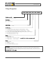
1
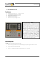
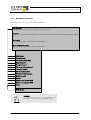
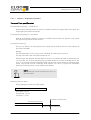
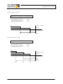
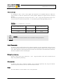
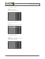
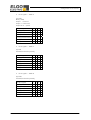
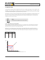
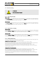
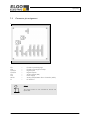
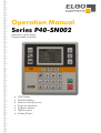
Operation Manual Series P40-SN002 Application metal shears Programmable controller LCD Display Simple handling Manual inching function Single set operation Program memory Digital outputs Analog Output Contents Content 1. General Information....................................................................................................... 4 1.1. Information Operation Manual ............................................................................. 4 1.2. Explanation of Symbols ......................................................................................... 4 1.3. Statement of Warranties ....................................................................................... 5 1.4. Demounting and Disposal..................................................................................... 6 2. Safety .............................................................................................................................. 7 2.1. 2.2. 2.3. 3. Transport General Cause of Risks ......................................................................................... 7 Personal Protective Equipment .............................................................................. 7 Conventional Use ................................................................................................. 8 and Storage ................................................................................................... 8 3.1. Safety Instructions for Transport/Unpacking and Loading ...................................... 8 3.2. Handling of Packaging Material ............................................................................ 8 3.3. Check of Transport ............................................................................................... 9 3.4. Storage ................................................................................................................ 9 4. Product Features ........................................................................................................... 10 5. Technical Data .............................................................................................................. 11 5.1. Dimensions......................................................................................................... 12 6. Configuration and Functions ........................................................................................ 13 6.1. Elements............................................................................................................. 13 6.1.1. Control Elements....................................................................................................... 13 6.1.2. Display Elements ....................................................................................................... 13 6.1.3. Function of Keys ........................................................................................................ 14 6.2. Menu, sections and parameters .......................................................................... 15 6.2.1. Axis Menu / Distances ............................................................................................... 16 6.2.1.1. Distance / Longitudes Parameters............................................................................... 17 6.2.2. Axis menu / times ...................................................................................................... 21 6.2.3. Axis menu / analog ................................................................................................... 23 6.2.3.1. Analog parameters ................................................................................................... 24 6.2.4. Axis menu / General ................................................................................................. 26 6.2.4.1. System parameters .................................................................................................... 27 6.2.5 Material Table .................................................................................................................... 31 6.2.5.1 Explanation of the Interpolation .................................................................................... 31 6.2.6 Menu / System .......................................................................................................... 32 6.3. Machine setting .................................................................................................. 34 6.3.1. Gap Setup (Cut gap) ................................................................................................. 34 6.3.2. Angle Setup (cut angle) .............................................................................................. 34 6.4 Configuration of inputs and outputs .................................................................... 35 6.4.1. Link-up the inputs with functions .......................................................................................... 35 6.4.2. Allocation to the logic input functions .................................................................................. 35 6.4.3. Linking the outputs of functions ........................................................................................... 35 6.4.4. Logic Allocation to Outputs ................................................................................................ 35 -2- Contents 7. Operation ....................................................................................................................... 36 7.1 Operation Modes .............................................................................................................. 36 7.1.1 Manual mode .................................................................................................................... 36 7.1.2 Single mode ....................................................................................................................... 36 7.1.3 Program mode ................................................................................................................... 36 7.1.3.1 Input of a program .......................................................................................................... 36 7.1.3.2. Handle of a program .................................................................................................. 37 7.1.4 Reference....................................................................................................................... 37 7.1.4.1 Function of reference drive ........................................................................................... 37 7.2 Connector pin assignment .................................................................................. 38 7.2.1 Overview Terminal Assignment ...................................................................................... 39 7.3 Diagnostics ....................................................................................................................... 40 8. Interferences .................................................................................................................. 41 8.1 Security .............................................................................................................. 41 8.2 Electrical interference suppression....................................................................... 42 8.3 Restart after fault clearance ................................................................................ 42 8.4 EMC information ................................................................................................ 43 9 Maintenance ................................................................................................................. 44 10 Type Designation ......................................................................................................... 45 11 Accessories .................................................................................................................... 46 -3- General Information 1. General Information 1.1. Information Operation Manual The manual contains important information regarding the handling of the controller. Precondition for safe operation is the compliance with the specified safety and handling instructions. Moreover, observe the existing local accident prevention regulation and general safety rules. Please read the operation manual carefully before starting to work. The manual should be kept accessible at anytime. The illustrations in the manual are for better representation of the facts they are not necessarily to scale and can be slightly different to the actual construction. 1.2. Explanation of Symbols Warning notices Warning notices are characterized by symbols in the operation manual. The notes will be introduced by signal words to express the magnitude of the danger. Follow these advices in order to avoid accidents and injuries to persons and property. DANGER! ... adverts to direct dangerous situations that can lead to death or severe injuries. CAUTION! ... advices to potentially dangerous situations that can lead to death or severe injuries. ATTANTION! ... advices to potentially dangerous situations that can lead to damages on property. -4- General Information Hints and commendations ADVERT! ...highlights helpful hints and recommendations for efficient and failure-free operation. Specific safety instructions The following symbols in conjunction with safety instructions are used in order to point out possible hazards: DANGER! ...marks perilous situations by electricity. By non-observance of the safety instructions the possibility of death or severe injuries exist. The operations have to be carried out only by an electrician. 1.3. Statement of Warranties The warranty conditions are in a separate document. Guarantee The producer guarantees the functional capability of the process engineering and the selected parameter. The period of warranty is one year and begins with the date of delivery. -5- General Information 1.4. Demounting and Disposal Unless otherwise authorized, dispose the item considering the safety instructions. Before demounting Disconnect the power supply Secure against re-start Disconnect supply lines physically and discharge remaining energy Dispose operating supplies with respect to the environment Disposal Recycle the decomposed elements: Scrap metal elements Recycle plastic parts Dispose the rest of the components according to their material consistence ATTENTION! Wrong disposal Î damage caused to the environment! Electronic waste, electronic components, lubricants and operating supplies are liable to treatment of hazardous waste. Only approved specialized companies should perform disposal. Local authorities and waste management facilities provide information about environmentally suitable disposal. -6- Safety 2. Safety 2.1. General Cause of Risks This chapter gives an overview about all important safety aspects to guarantee an optimal protection of employees. Non-observance of the instructions mentioned in this operation manual can result in hazardous situations. 2.2. Personal Protective Equipment Employees should wear protective clothing during installation of the device to minimize the risk of accidents. Therefore: Change into protective clothing before beginning the work process. Also observe any labels in the operating area regarding protective clothing. Protective clothing Safety working clothing ... is close-fitting ... is tear proof ... has tight sleeves without distant parts Also wear no rings, necklaces or other jeweler. Protective gloves ... for protecting the hands against abrasion and cuts -7- Conventional use, Transport, Storage 2.3. Conventional Use The controller P40 is for the limited purpose as described in this manual: The controller P40 is constructed for positioning uses only. CAUTION! Danger through non-conventional use! Non-intended use and non-observance of this operation manual can lead to dangerous situations. Therefore: Use P40 only as described Strictly follow this manual Avoid in particular: Remodeling, refitting or changing of the device or parts of it with the intention to alter functionality or scope of the position controller. ELGO is not liable for any damages resulting from improper use of the product. 3. Transport and Storage 3.1. Safety Instructions for Transport/Unpacking and Loading ATTENTION! Professional transport only. Do not throw, hit or fold the package. 3.2. Handling of Packaging Material Adverts for proper disposal refer to 1.4. -8- Conventional use, Transport, Storage 3.3. Check of Transport Examine delivery immediately after receiving for completeness and transport damages. In case of externally recognizable transport damages: Do not accept the delivery or do accept under reserve Note extent of damages on the transportation documents or on the delivery note File complaint immediately ADVERT! Claim any damages you recognize as soon as possible. The claims for damage must be filed in the lawful reclaim periods. 3.4. Storage Store device only under following conditions: Do not store outside Keep dry and dust-free Do not expose to aggressive media Protect from direct sun light Avoid mechanical shocks Storage temperature: 20 to + 50 °C Relative humidity: 60% non-condensing Inspect packages regularly if stored for an extensive period of time (> 3 months) -9- Product Features 4. Product Features Essential features: Analog or digital outputs for 1 - 3 speed operation 16 free programmable digital in-/outputs Program memory (1000 sets) Angle control / gap control / backgauge Limitation of the cutting length Material List for angle and gap control The single axis controller of P40 series is applicable to easy positioning tasks. An important feature is the easy structured function menu. It allows a quick and comfortable setting of the target value, if necessary a specific quantity of desired pieces, an angle or the gap. Target and actual value of the axes plus quantity will be displayed on the front panel. The keyboard is simple and user-friendly. With the inputs the cutting angle or gap can be displayed and controlled. These encoder inputs work in an analog mode. A back stop can be programmed. The P40 series has an internal program memory with up to 1000 lines. For the positioning two different kinds of output signals are available: Switch mode positioning and PID-analog output. The P40 series can alternatively be supplied with 24VDC or 24VAC. An optional serial interface allows data transmission for communication with a superior system. Basic modes of operation: The P40 consists of three general operation modes: 1. Manual: Inching operation moves the axes through operating the keypad or external switches. 2. Single: A whole set can be worked off. 3. Program: In this operation mode a programmed set can be worked off. - 10 - Technical Data 5. Technical Data P40 – ELGO-position controller Input supply voltage 24 VDC Power input 24 VDC; max. 150 mA (no-load condition) Rotary encoder supply unit 24 VDC or 5VDC ; max. 130 mA Analog input (option) 12 Bit resolution ; 3,3 V Supply measuring system Input signals The Pin assignment of the inputs and the input logic are programmable Minimum pulse duration: 300 ms Input current /Pin: max. 10 mA Output signals The Pin assignment of the outputs and the output logic are programmable Open Emitter (PNP) Complete short-circuit-proof Output current: max. 80 mA Recovery diode is integrated Actual value memory E² Prom Durability: 105 On-Off-Switch-Cycle or 10 years Connection technology Phoenix Connectors Displays LCD Dot-Matrix 128 x 80 mm with white backlight Hardware 32-Bit-Microprocessor with 1 MByte Flash 56 Kbyte RAM System accuracy +/ -1 Increment 15 KHz (upgrade on enquiry possible) equals by 0,1 mm resolution: 120 m/min. (2 m/s) W x H x D = 144 mm x 144 mm x 40 mm (without connector) Input frequency Housing dimensions Disruption degree Installation depth without connector Installation depth with connector Ambient temperature W x H = 136 mm x 136 mm 40 mm 75 mm 0 to +45 °C - 11 - Technical Data 5.1. Dimensions - 12 - Configuration and Functions 6. Configuration and Functions 6.1. Elements 6.1.1. Control Elements Escape Menu navigation Manual/Single Forward/backward/Enter Program-Mode Function keys Input Start Stop 6.1.2. Display Elements Program Number Set Number Symbol Operation mode Backgauge Quantity Position Mode Gap Angle Material Cutting Length Material Thickness - 13 - Configuration and Functions 6.1.3. Function of Keys Change Operation mode between „Manual“ and „Single“ Operation Mode “Program” Leaving an Operation Mode or a Sub menu Select or Confirm Cursor navigation „up“ Cursor navigation „down“ ... Function keys (addicted to Menu or Operation mode) Clear or reset an input Change of Sign ... Enter Target Value or Parameter value Start Positioning Stop Positioning - 14 - Configuration and Functions 6.2. Menu, sections and parameters Main menu Due to the display size only five menu levels are visible. The further (momentarily invisible) levels are located beneath. Operation Modes Manual Mode Single Mode Program Mode Service Parameter System Backgauge Distances Times Analog System Gap Distances Times Analog System Angle Distances Times Analog System Settings Default Parameter Password I/O-Configuration Input Function Input Logic Output Function Output logic Setup Gap Angle Cutting Length Diagnosis Inputs Outputs Keys Version - 15 - Configuration and Functions 6.2.1. Axis Menu / Distances Relevant distances for the axes can be set in this menu. Axis distances Access to parameters concerning distances e.g. speeds etc. Axis times Access to parameters concerning times e.g. position reached, zero speed monitoring, rotary encoder etc. Axis analog Access to parameters concerning the analog output. General Parameters Axes Access to general parameters concerning the axes. Slow forward Creep forward Correction stop forward Slow backward Creep backward Correction stop backward Tolerance window Spindle compensation Window Forced tolerance Reference value Retract Software-end position MIN Software-end position MAX Factor Blade Length HINWEIS! Im Menü Achse Strecken der Winkelachse kann zusätzlich noch die Messerlänge eingegeben werden. - 16 - Configuration and Functions 6.2.1.1. Distance / Longitudes Parameters Slow speed/Creep speed/Correction Slow speed/slow speed (r) = middle speed Distance to the demand position at which the controller switches from high speed to slow speed. The output high speed will be switched off. Creep speed/creep speed (r) = slow speed Distance to the demand position at which the controller switches from slow speed to creep speed. The output slow speed will be switched off. Correction/correction (r) The over run distance can be programmed to compensate for distance from the switch-off point of the motor to standstill. Example: The demand position is over run by 0.2 mm constantly. The data entry has to be 2. The stop command is then moved forward by 0.2 mm. With starting of the operation the stop offset is set first to "0" in order to be able to calibrate the over run accurately. For an exact positioning the stop offset should be as small as possible (0.0 to 0.2 mm) i.e. the mechanical friction should be steady over the entire retract distance and the slow speed and/or creep speed must be accordingly small adjusted. The value in register slow speed/slow speed (r) must be larger than in creep speed/creep speed (r). NOTE! When positioning with PID correction stop serves as a tolerance window. Positioning with one speed During setting the speeds in principle applies: Slow speed = Creep speed = Correction Slow speed: 1,0 mm Creep speed: 1,0 mm Correction: 1,0 mm Position reached 100,0 Slow speed/Creep speed Correction stop - 17 - Configuration and Functions Positioning with two speeds Slow speed = Creep speed > Correction stop Slow speed/Slow speed (r) Creep speed/Creep speed (r) Correction/Correction (r) = 10.0 = 10.0 = 1.0 Position reached Fast Slow speed/Creep speed 100,0 Correction stop 90,0 99,0 Slow Positioning with three speeds Slow speed > Creep speed > Correction stop Slow speed/Slow speed (r) Creep speed/Creep speed (r) Correction/Correction (r) = 20.0 = 10.0 = 1.0 Fast Slow speed Creep speed Position reached 100,0 Correction stop Slow Middle 80,0 90,0 99,0 - 18 - Configuration and Functions Tolerance window It is possible to enter a value in this register that represents an acceptable tolerance. When the actual position is within the tolerance the actual position displayed is aligned with the demand position. The entered range of tolerance is always active in the + and – range around the demand value. The real actual value is saved in the processor, i.e. no positioning errors through adding up occur. Example: Entered value = 0.2 (tolerance +/ 0.2 mm) Display without tolerance Display with tolerance 99.8 Actual display 100.0 100.0 Target window 100.0 ADVERT! The tolerance window should be set to zero before starting to operate. Spindle Compensation In order to adjust spindle tolerances the demand position must be approached always from the same direction that means that in one direction the demand position will be overrun by the entered value. After expiration of the backlash dwell time that was entered (menu/times/backlash dwell time) the demand position will be reached again. Window forced tolerance A loop is driven if the value is within the + and – range around the value oft he “window forced loop” using absolute positioning. Reference value A reference value and a reference position can be entered respectively. By using the external reference input the reference value is used as the demand value. Retract The retract distance can be entered in mm in this parameter. - 19 - Configuration and Functions Software-end position MIN/MAX These two values can be used if no mechanical limit switches are present or additionally for already existing mechanical limit switches. End position min.: This value should be between the smallest length/position that hast o be worked off and zero (and shortly before the mechanical limit switch respectively). End position max.: This value should be between the largest length/position that has to be worked off and the maximum length (and shortly before the mechanical limit switch respectively). If one of these two values is reached, the positioning procedure is interrupted. Factor A factor (0.00001 to 9.9999) can be entered in this Register. The incoming pulses will be multiplied by this factor, to manipulate the display to required dimensions. If no multiplication is required, this Register must be set to 1.00000. Example: rotary encoder = 1000 [pulses] [RPM] Spindle distance = 100 [mm] [RPM ] Factor = Spindle distance [mm] 100 [mm] [mm] = = 0,1 pulses 1000 [pulses] [pulse] Blade length Here, the maximum blade length can be entered (in mm). With this the maximum input length of the cutting length in single mode and program mode will be defined. If no blade length (parameter value = 0) will be defined, the cutting length in single or program mode will be percentage calculated. - 20 - Configuration and Functions 6.2.2. Axis menu / times The times relevant for the respective axes can be entered from 0.1 to 99.9 seconds. Axis distances Access to parameters concerning distances e.g. speeds etc. Axis times Access to parameters concerning times e.g. position reached, zero speed monitoring, rotary encoder etc. Axis analog Access to parameters concerning the analog output. General Parameters Axes Access to general parameters concerning the axes. Position reached Spindle compensation Velocity change manual mode System monitoring Fall-delay time controller enables Start delay time Shutdown Position control Retract Reversal Reference drive - 21 - Configuration and Functions Parameter of time Position reached The signal is based on a variable time during input of a time value or statically/maintained (axis in position) if the value is set to 0. The appropriate output signal becomes active if: Actual value = demand value +/– stop offset By reached position the signal is switched to pulsed if a value (0.1 … 99.9 sec) is entered into the register „position reached“. Spindle compensation In the peak of the loop drive, the drive signals drop-out. The controller returns to the target value when the parameterized time expires (adjustment range 0.1 sec - to 99.9 sec). Velocity change manual mode Here the time in hand can be entered to set the speed from the low speed to the next higher speed. System monitoring For encoder monitoring a time can be entered (0.1... 99.9 seconds). If for the entered time no more pulses are detected at the controller in order to stop the engine, the operating signals are switched off. Fall-delay time controller enables After the start command the output "closed loop inhibit” is activated. After reaching the intended position and only after the operational sequence (0.1 … 99.9 sec) in register “time delay for drive inhibit” is worked off the output is set back. Start delay time With an initial instruction the start of the positioning is delayed for the entered time. Shutdown Position Control Here the time in 0.1 sec. can be entered for shutdown after the position is reached. Retract Here the time in 0.1 sec. can be entered for return from the peak of the retract to the target value. Reversal Reference drive In the peak of the reference run, the drive signals drop-out. The controller will continue positioning when this time expires (adjustment range 0.1 sec - to 99.9 sec). - 22 - Configuration and Functions 6.2.3. Axis menu / analog The axis relevant analog parameters can be set in this menu. Axis distances Access to parameters concerning distances e.g. speeds etc. Axis times Access to parameters concerning times e.g. position reached, zero speed monitoring, rotary encoder etc. Axis analog Access to parameters concerning the analog output. General Parameters Axes Access to general parameters concerning the axes. Velocity Accelaration P-portion I-portion D-Position I-Limit Pulses encoder Stop mode v Manual fast forward v Manual slow forward v Reference mode part 1 v Reference mode part 2 Advert! The Parameter for analog mode are only necessary for devices with option PID. - 23 - Configuration and Functions 6.2.3.1. Analog parameters Velocity The maximum speed is set in this register, in rpm. The speed is monitored by the encoder speed (0 – 10000 rpm). Should there be gearing between the motor and the encoder this has to be considered in the calculations. EXAMPLE! Demanded motor speed rpm = 3000 Gearing ratio i = 10 V = RPM/i = 3000/10 = 300 Edge multiplier and impulse multiplication factor has not to be considered. Acceleration The acceleration during positioning in revolutions per second squared is set in this parameter. P-portion Proportional amplification: setting 1…..3000 General: The P-controller exclusively consists of a proportional portion and has thereby its characteristics. In principle the p term multiplies the input value by a coefficient. P40: By offset the difference between the demand and actual value is multiplied by the entered value and shown as power-sharing. The bigger the proportional amplification the more sensitive the control loop will be (possibly even unstable). I-portion / I-Limit Integral step: setting 1….1000 General: An I-controller (integrating controller) provides the control value through timed integration of the offset taking the reset time into account. A continuing offset leads to further increase of the analog output. The reset time determines how big the temporal influence is. The maximum reset time is limited by I-limit. The step response of the I-portion is a linear increase. That means for a constant offset the integral will be increased and thus reinforces the I-portion. P40: By offset the analog control voltage will continue to increase step by step until there is zero difference between demand and actual position and the entered I-limit in this register is reached respectively. The greater the I-portion, the slower is the response. - 24 - Configuration and Functions D-portion Differential voltage: setting 1...1000 General: The D-controller (differential controller) provides the control value from the derivative with respect to time oft he offset. P40: By offset a short voltage pulse proportional to the rate of change will be put out to compensate quickly without sacrificing the stability of the control loop permanently. The value of the voltage pulse is entered. (max + / - 10 V). Pulses encoder Rotary encoder resolution: The encoder pulses per revolution are entered in this register. This enables the calculation of speed to be effected (max. 10000 ppr). Stop mode For the different possibilities to stop the system the P40 comes with this special register. 0= 1= 2= Stop smoothly (Stop ramp = negative acceleration R51) Stop abrupt (Stop ramp = highest possible negative acceleration) Stop turn off motor (Analog signal is set to zero) v Manual fast forward Here the fast speed can be set for moving the axes in manual mode. v Manual slow forward Here the slow speed can be set for moving the axes in manual mode. v Reference mode part 1 Here the reference run speed of the back gauge until reaching the initiator is defined. v Reference mode part 2 Here the reference run speed of the back gauge until reaching the index pulse is defined. - 25 - Configuration and Functions 6.2.4. Axis menu / General System relevant general parameters can be entered in this register. Axis distances Access to parameters concerning distances e.g. speeds etc. Axis times Access to parameters concerning times e.g. position reached, zero speed monitoring, rotary encoder etc. Axis analog Access to parameters concerning the analog output. General Parameters Axes Access to general parameters concerning the axes. Positioning measurement system Direction change manual Drive signals Mode reference Spindle compensation Software-end position Hardware-end position Retract function Relative error compensation - 26 - Configuration and Functions 6.2.4.1. System parameters Positioning measurement system The type of measurement system is defined in this parameter. Axis deactivated Microcontroller PID Controller Analog potentiometer Direction change manual The allocation of the direction for the corresponding keys can be set as inverted in this parameter. normal inverted Drive signals With configuration of the motor signals different starting combinations for the different speeds can be set. Drive signals = Mode 1 3 speeds (ELGO-standard) Speed = output signals 1-3 ascending Output 4 sets direction reverse Output signals Creep speed forward Slow speed forward Fast speed forward Creep speed backward Slow speed backward Fast speed backward 1 X X X X X X 2 3 X X X X X X 4 X X X Drive signals = Mode 2 2 speeds Independent outputs forwards and reverse (additional information BCD-Code: cca553) Independent outputs fast and slow Output signals Creep speed forward Slow speed forward Fast speed forward Creep speed backward Slow speed backward Fast speed backward 1 X 2 X X 3 4 X X X X X - 27 - Configuration and Functions Drive signals = Mode 3 2 speeds speed = output signals 2 + 3 output 4 set direction reverse Output signals Creep speed forward Slow speed forward Fast speed forward Creep speed backward Slow speed backward Fast speed backward 1 X 2 X X X X 3 4 X X X X X Drive signals = Mode 4 2 speeds Independent outputs for direction and speed Output signals Creep speed forward Slow speed forward Fast speed forward Creep speed backward Slow speed backward Fast speed backward 1 X 2 3 4 X X X Drive signals = Mode 5 3 speeds Speed forward = output signals 1-3 ascending Speed backward = always fast output 4 sets direction reverse Output signals Creep speed forward Slow speed forward Fast speed forward Creep speed backward Slow speed backward Fast speed backward 1 X X X X X X 2 3 4 X X X X X X X X X X X X - 28 - Configuration and Functions Drive signals = Mode 6 3 speeds Binary coded output 1 = forward output 4 = backward outputs 2+3 = speed Output signals Creep speed forward Slow speed forward Fast speed forward Creep speed backward Slow speed backward Fast speed backward 1 X X X 2 X X X 3 4 X X X X X X X X 2 3 4 X X X Drive signals = Mode 7 3 speed Forward/backward separately Output signals Creep speed forward Slow speed forward Fast speed forward Creep speed backward Slow speed backward Fast speed backward 1 X X X X X X X X X 2 3 4 Drive signals = Mode 8 2 speeds Forward/backward separately Output signals Creep speed forward Slow speed forward Fast speed forward Creep speed backward Slow speed backward Fast speed backward 1 X X X X X X X X X - 29 - Configuration and Functions Mode reference The mode for referencing is defined in this parameter. Mode 1 = Calibration through reference parameter Mode 2 = Calibration through demand value Mode 3 = Reference run positive with index impuls Mode 4 = Reference run negative with index impuls Mode 5 = Reference run positive to input “reference point” Mode 6 = Reference run negative to input “reference point” Backlash compensation The different types of backlash compensation (loop) are defined in this parameter. No spindle compensation Negative spindle compensation Positive spindle compensation With backlash by positioning in negative direction With backlash by positioning in positive direction Software-end position Software-end positions can be activated or deactivated in this parameter. All end positions active End position min deactivated End position max deactivated All end positions deactivated Hardware-end position Hardware-end positions can be activated or deactivated in this parameter. All end positions active End position min (defined input) deactivated End position max (defined input) deactivated All end positions deactivated Retract function The type of descent is defined in this parameter. Mode 1 = Descent/retract to actual value + adjusted value* Mode 2 = Descent/retract to adjusted value* Mode 3 = Descent/retract positive to actual value for the adjusted time period** Mode 4 = Descent/retract to actual value + adjusted value* without return Mode 5 = Descent/retract to adjusted value* without return Mode 6 = Descent/retract positive to actual value for the adjusted time period** without return Mode 7 = Descent/retract to actual value – adjusted value* Mode 8 = Descent/retract negative to actual value for the adjusted time period** Mode 9 = Descent/retract to actual value – adjusted value* without return Mode 10 = Descent/retract negative to actual value fort he adjusted time period** without return * see parameter descent/retract distance ** see parameter time descent Relative error compensation If activated the controller compensates for errors that may add up doing a lot of drives. active not active - 30 - Configuration and Functions 6.2.5 Material Table In this table the material specific experienced values for cut angle and gut gap can be entered in this parameter. The more inputs are made the more precise the non-existing values in the table can be calculated through interpolation. By operating one set or more sets the only values that have to be entered are the kind of material (material no.) and the metal sheet thickness. The buttons F1 and F3 are used to scroll through the material table. The button F2 is used for switching with the cursor from one column to another column. The values have to be higher than zero in both columns. If the value is zero the relevant line will be detected as the end of the material table. As a result of this all subsequent values won’t be recalled. Advert! The values have to be higher than zero in both columns. 6.2.5.1 Explanation of the Interpolation Because of that it is possible to deposit only values in 1mm sequences, the values between this sequences will be interpolated. The calculation of the intermediate steps take as a basis of two sequenced material thicknesses for the action of the values of gap and angle. Example: The red marked values are firmly rooted in the material table. Now a value for the material thickness of 2.5 mm will be loaded. For the clarity in this example, only the calculation of the value of the gap is illustrated. The calculation of the intermediate steps for the angle according to the same principle. Thickness 1 2 3 4 5 … Gap 0.10 0.20 0.30 0.40 0.50 … Angle 0.75 1.00 1.25 1.50 1.75 … Gap Spalt 0.5 0.4 0.3 0.2 0.1 1.0 2.0 3.0 4.0 5.0 Mat.-Stärke Material [mm] thickness in mm - 31 - Configuration and function 6.2.6 Menu / System Adjustment Access to system parameters. Default Parameter Reset to factory parameters Password Enter the Password Language Axes active Mode pieces counter single block Mode pieces counter program Block size Block shift Time Block shift Leaving EDIT Mode Cutting length - 32 - Configuration and Functions Language German English Axes active Backgauge + Gap + Angle Backgauge + Gap Backgauge + Angle Backgauge Mode pieces counter single block The mode pieces counter for the single mode can be defined here. Without counter Automatically subtracting Automatically adding Mode pieces counter program The mode counter fort he program mode can be defined in this parameter. automatically subtracting automatically adding Block size 1 5 10 20 25 50 75 100 Block shift Auto start after changing a set is defined in this parameter. Not active After set without start After set with start Time Block shift The time frame from the end of a set to the start oft he new set is defined in this parameter. 1/2/3/4/5 sec. Cutting length not active active - 33 - Configuration and Functions 6.3. Machine setting ATTANTION! First check end-switch function! 6.3.1. Gap Setup (Cut gap) Minimum gap: Enter the small cut gap of the shear (e.g. 0.5 mm) and after that drive manually to the smallest position by using F1-key or F3-key. When reached this position press the F2-key (teach). The incremental measurement value is assigned to the gap and entered in the field “min.” is saved. Maximum gap: Enter the large cut gap of the shear (e.g. 10.0 mm) and after that drive manually to the largest position by using F1-key or F3-key. When reached this position press the F2-key (teach). The incremental measurement value is assigned to the gap and entered in the field „max.” is saved. 6.3.2. Angle Setup (cut angle) Minimum angle: Enter the small possible cut angle of the knife bar (e.g. 0.0°) and than drive manually to the smallest position by using F1-key or F3-key. When reached this position press the F2-key (teach). The incremental measurement value is assigned to the angle and entered in the field “min. “is saved. Maximum angle: Enter the large possible cut angle oft he knife bar (e.g. 10.0°) and then drive manually to the largest position by using F1-key or F3-key. When reached this position press the F2-key (teach). The incremental measurement value is assigned tot he angle and entered in the field „max value“is saved. 6.3.3. Cutting length Setup If the same analog measuring system which is used for the angle also used for the angle Cutting length, then it is necessary, set the values for the cutting length calculation. Setting values with minimum angle: Place the cursor in the first row and first column of the table (line: min; column: S. Beg). Now, enter the smallest possible cut angle. Let down the cutting blade to beginning of the cut (till the point, where the upper beam and lower beam of the scissors just touch) and press the F2 key. Now place the cursor on the field in the first row and second column (row: Min; column: S. End) and let down the cutting blade to the end of the cut. Now press the F2 key again. Thus the values for the minimum angle are set up. Setting values with maximum angle: Place the cursor in the second row and second column of the table (line: max; column: S. Beg). Now, enter the biggest possible cut angle. Let down the cutting blade to beginning of the cut (till the point, where the upper beam and lower beam of the scissors just touch) and press the F2 key. Now place the cursor on the field in the first row and second column (row: Max; column: S. End) and let down the cutting blade to the end of the cut. Now press the F2 key again. Thus the values for the maximum angle are set up. - 34 - Configuration and Functions Configuration of inputs and outputs With the controller P40 it is possible to configure feely the inputs and outputs with their associated logic. 6.4.1. Link-up the inputs with functions In the menu “Input functions” you will find an overview of all functions of the inputs which can be assigned. After dialing a function by using the navigation buttons you can select this function by pressing the Enter key. If a previously used input is needed to be reset, you can use the "delete key" to dial it in the "not used" state. In the case of multiple input functions with a single external signal, the inputs can also be assigned several times. ADVERT! Inputs can also be assigned several times. 6.4.2. Allocation to the logic input functions If you are as specified in section 6.4.1 the inputs of the controller with functions, then you can use this menu to define whether the corresponding input function to a logical "High" - level or at a logical "low". Assigning the logic takes place by pressing the enter key. 6.4.3. Linking the outputs of functions In the menu “Output functions” you will find an overview of all functions of the outputs which can be assigned. After dialing a function by using the navigation buttons you can select this function by pressing the Enter key. If a previously used output is needed to be reset, you can use the "delete key" to dial it in the "not used" state. A repeated Assign of the outputs is not possible here and is from the outset of the software prevented. If an output is already set with a function, then automatically only the next free output is selectable. ADVERT! Outputs can not be assigned several times. 6.4.4. Logic Allocation to Outputs At the outputs it is also possible depending on the selected output function to assign a logic. The set follows the same procedure as in Section 6.4.2. - 35 - Operation 7. Operation 7.1 Operation Modes 7.1.1 Manual mode With the keys F1 & F3 the axis shown in the display can be driven manually or with the inching function. In register “delay hand” a time (in sec) can be set. If the hand mode is selected and the entered time value is worked off the manual mode will automatically switch from creep speed to fast speed. 7.1.2 Single mode Using the single mode (single set mode) a single set can be processed. The arrow keys can be used for navigation. The inputs of the values in the target window are done manually. Every input has to be select by pressing the Enter button. To load deposited values of the material table, you have to select the respective material number in menu “Mat:” at the lower boarder of the display. After dialing you can select the material number by pressing the Enter button and the values will be loaded according to the actual action of positioning. 7.1.3 Program mode Using the program mode up to 1000 individual programs can be programmed and individually driven. All positions are successively driven. This process must be started once using the start command. 7.1.3.1 Input of a program Starting the program mode will open an input window in which the desired program number can be entered. After this operation the “Enter key” has to be pressed to open the program window. At first start the user has to enter a memory block number. Entering the memory block number is only necessary if the user is in the first data set of the program is. To ensure faster entry in all other data sets only the following elements have to be changed: Target value Backgauge Position mode Set Number Quantity Cutting length If you are in input mode then the cursor is blinking. To end the entry you have to press the enter key to confirm. The last entered value will be immediately saved. The buttons F1 and F3 are used to navigate through the individual program sets. Also it is possible to select the set number with the cursor and adjust the corresponding set number. Also it is possible to load material values out of the material table for Angle and Gap with select the kind of material. More detailed information about material table you can see in the corresponding chapter. If all elements edited you have to select the menu element “Set number” by using the cursor and then press the button F2. This will end the program in the last row and the last set will be marked with the letter 'E'. - 36 - Operation 7.1.3.2. Handle of a program The program mode can be select directly by using the program button. First, choose a program by entering a program number, and confirmed with the Enter key. With the keys F1 and F3 you can scroll again through all the sets. The automatic positioning starts by pressing the Start button. Now, all sets will be processed until the end marker of the program is reached. The positioning process can be intercepted by pressing the stop button at any time. The program remains in the current set. To restart the program press the start button again. 7.1.4 Reference The following parameter settings can be selected in the menu Parameters -> axes -> General Axes Parameter -> Mode reference: Mode "parameters": If this is selected and the external reference input is active or F2 - button will be pressed for more than two seconds, then the stored value from the menu Parameters->Axes->Distances->Reference value will be brought in the actual value window for this axis. Mode "over target value": If this is selected and the external reference input is active or F2 - button will be pressed for more than two seconds, then the entered value from target position will brought in the actual value window for this axis. Mode "positive drive": To limit switch with index pulse (see Section 7.1.4.1) Mode "negative drive": To limit switch with index pulse (see Section 7.1.4.1) 7.1.4.1 Function of reference drive The reference run will be started by holding the button F2 for more than 2 seconds. A “start reference run” by using the external input for reference is not possible. The controller now proceeds to referencing the axis in dependence of the parameter: Parameter -> Axes -> General -> Mode reference. The output “reference drive run” is set. If the appropriate input (limit switch positive or negative) is activated, the controller stops. After a dwell time the controller position in the opposite direction. Once the appropriate input (limit switch) is disabled, the input “zero pulse” will be released. For the next zero pulse the controller stops and the value of the register Axes -> Reference will be transferred in the actual value window. From this point you have to differ respective to the menus: • In Manual mode menu the reference is completed from this moment. • In Single mode menu the backgauge position to the target value. • In Program mode menu the backgauge position to the first target value of the first set of the actual selected Program. - 37 - Operation 7.2 Connector pin assignment ST1 ST2 ST3/ST4 ST5/ST6 ST7 ST9 MCC1 P1 = = = = = = = = Encoder input Backgauge Encoder input Angle and Gap Digital Inputs Digital Outputs Analog Output (PID) Power supply Analog Output/Motor Drive Controller (MCC) PC Interface Advert! The Analog Output is only available for devices with Option PID. - 38 - Operation 7.2.1 Overview Terminal Assignment ST1 Encoder Backgauge 1 GND 2 5VDC/24VDC 3 A‐Channel 4 B‐Channel 5 Earth 6 /A‐Channel 7 /B‐Channel 8 Z‐Channel (Index pulse) 9 /Z‐ Channel (Index pulse) ST3 Inputs 1 GND 2 24VDC (Output) 3 Limit Switch Min. Axis 1 4 Limit Switch Min. Axis 2 5 Limit Switch Min. Axis 3 6 Limit Switch Max. Axis 1 7 Limit Switch Max. Axis 2 8 Limit Switch Max. Axis 3 9 10 ST5 Outputs 1 GND 2 +24VDC (Output) 3 Drive Signal 1 Axis 1 4 Drive Signal 2 Axis 1 5 Drive Signal 3 Axis 1 6 Drive Signal 4 Axis 1 7 Drive Signal 1 Axis 2 8 Drive Signal 2 Axis 2 9 Drive Signal 1 Axis 3 10 Drive Signal 2 Axis 3 ST7 Analog Output (PID) 1 GND 2 Analog‐target Value +/‐ 10VDC 3 Earth MCC1 Analog Output/Motor Controller MCC 1 Controller Enable 2 3 A‐Channel 4 B‐Channel 5 /A‐Channel 6 /B‐Channel 7 Analog‐target Value +/‐ 10VDC 8 GND ST2 Encoder Gap and Angle 1 GND 2 3,3VDC Supply 3 Analog Input Gap 0..3,3VDC 4 5 Earth 6 7 8 9 Analog Input Angle 0..3,3VDC ST4 Inputs 1 GND 2 24VDC (Output) 3 Stop Positioning 4 Start Positioning 5 Retract Axis 1 6 Reference Axis 1 7 Counter (add. / subtr.) 8 9 10 ST6 Outputs 1 GND 2 24VDC (Output) 3 Controller Enable Axis 1 4 Reference Drive Run Axis 1 5 Quantity reached 6 Cutting Enable 7 Cutting Length reached 8 9 10 ST9 Supply 1 GND 2 24VDC 3 Earth P1 PC‐Interface 1 GND 2 RS232 RX 3 RS232 TX 4 CAN L (Option) 5 CAN H (Option) 6 MD0 (Special) 7 MD1 (Special) 8 MD2 (Special) - 39 - Operation 7.3 Diagnostics The modules for inspecting, maintenance, control and safety/security are provided in this register: (1) (2) (3) (4) Input test – The inputs can be inspected with this function. Output test – The outputs can be inspected with this function. Keyboard test – The functioning oft he keys can be ensured in with this test. Version info – The installed software version is displayed with this function. - 40 - Interferences 8. Interferences The following chapters describe possible causes for malfunction and the instructions to correct them. If you encounter problems check for proper installation first. Make sure that power is supplied to the system. If you observe recurring errors you might consider electrical interference suppression measures as described in section 8.2 If errors cannot be corrected with the following instructions please contact the manufacturer (see last page). 8.1 Security Basics CAUTION! Risks of injury from improper fault clearances! Improper fault clearances can cause serious personal or property damage. Therefore: Fault clearance may only be carried out by qualified and instructed personnel Prior to the beginning of work provide sufficient room to assemble the equipment Please look for cleanliness at the place of installation; loosely around laying parts and tools are sources of accidents If components have to be replaced: Look for correct installation of spare parts All mounting elements have to be assembled correctly Before resetting please ensure that all covers and protective devices are installed correctly and function properly To ensure a perfect operation of the controller the following (external) measures have to be taken additionally: Place of installation: The controller should not be installed near to sources of interference generating strong inductive or capacitive interferences or strong electrostatic fields. Install the external power supply directly beside the controller to avoid long low voltage wires. Power supply: Connect the external power supply to a phase of 230 VAC or 115 VAC which is not used for engines. If not possible use a galvanic separation over an additional transformer. Wire installation: Install all wires for low voltages and encoders always separately from power wires (230 VAC/400 VAC). Avoid installing these wires close to any contactor or contactor wires. - 41 - Interferences Shielding: All external signal wires have to be installed shielded: 1. Rotary encoder wires and analog input wires 2. Wires for all other input signals 3. Wires for all output signals 4. Wires from the power supply to the controller All shields have to be connected centrally low ohm to PE (earth potential), connect only one sided at the controller. ADVERT! Do not connect the controller / measuring system GND to PE (protective earth). Do not connect the shielding on both sides to PE (protective earth). If the PE potential is heavily “contaminated” by interference voltages try to connect the shielding to the GND potential instead of PE (protective earth). 8.2 Electrical interference suppression Signal wires should be installed separately from load power lines and with a safe distance of at least 0.5 m to capacitive and inductive interferences such as contactors, relays, motors, switching power supplies, timed controllers. If interferences occur in spite of applying all above mentioned measures proceed as follows: 1. Add RC elements over contactor coils of AC contactors (for example 0,1 µF/100 Ω) 2. Add recovery diodes over DC inductances 3. Add RC elements over each drive phase (in connector box of the drive). 4. Do not connect the GND potential with PE (earth potential)! Install a power filter before the external power supply 8.3 Restart after fault clearance After fault clearance: 1. Reset emergency stop switch. 2. Quit disturbance on controller. 3. Make sure that no person is located in the danger zone. 4. Start operating as explained in the instructions. - 42 - Interferences 8.4 EMC information A trouble-free operation of the control devices of the company ELGO Electric GmbH can only be guaranteed if in assembly, wiring and operating the following basic rules are observed and adhered to: • • • • • • Use only shielded signal lines with a minimum diameter of 0.15 mm² To protect against electrical fields, connect the cable shield unilaterally, low resistance and Low inductive with the operating lightning protection. Unused arteries in signal lines should be isolated from each other separately isolate signal and power lines separately in long parallel lines (a distance of 300 mm is respected ) Therefore, should never be different voltage levels, e.g. 230V/50 Hz power supply and measuring Signal 24V DC in one cable together low the emission by the Installation of filter networks in plants with frequency. In the operating Instructions of the manufacturer FU find the appropriate instructions. Wireless phones and Walky-talkies should never be used in the immediate vicinity of electronic Devices - 43 - Maintenance 9 Maintenance The unit works maintenance-free. - 44 - Type Designation 10 Type Designation P40 – XXX – 024 – XX – XX - XXXX Positioning controller Single axis with program memory Construction 000 = standard 001 = special version … Supply voltage 024 = 24 VDC (+/- 20%) Encoder inputs X = Not equipped 0 = A, B (PNP) 24 VDC supply voltage for encoders/24 VDC – 20 KHz 1 = A, B, 0 (PNP) 24 VDC supply voltage for encoders/24 VDC – 20 KHz 2 = A,/A, B, /B (TTL) 24 VDC supply voltage for encoders 5 V-TTL – 100 KHz 3 = A, /A, B, /B, 0, /0 (TTL) 24 VDC supply voltage for encoders 5 V-TTL – 100 KHz 4 = one analog Input (only for 2nd axis) 5 = two analog Inputs (only for 2nd axis) Outputs X = Not equipped 0 = Digital Outputs (PNP) 1 = Analog output +/- 10V (PID regulated) - not possible with analog measurement system! 2 = Analog output 0… 10V (on request) Options X = Not equipped C = Clamps S = Serial interface RS232 EN = input NPN (including index pulse) For exmaple: P40 – Application Metal Shears with 24 VDC supply, 1 input with A, B, Z signal and two analog inputs, for first axis analog output +/- 10V (PID regulated) for the second axis transistor outputs, connection with screw clamps and RS232 interface: P40 - 002 - 024 - 15 - 10 – CSXX - 45 - Accessories 11 Accessories NG 13.0 Power supply Primary: 115/230 V AC Secondary: 24 V DC/600 mA Relay outputs over separate relay card RP16K and connector cable available Document- No.: 799000348 / Rev. 1 DocumentP40-002-E_30-10 Name: Subject to change - © 2010 ELGO Electronic GmbH & Co. KG - 46 - Imprint