1
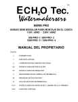
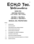
TM
E C H2O Tec.
Watermakers
PRO SERIES
VERTICAL SYSTEM
115V / 60HZ - 230V / 60HZ
500-PRO-1 / 900-PRO- 2
1200-PRO- 3 / 1500-PRO- 4
OWNERS MANUAL
PAGE
2
INTRODUCTION
3
SPECIFICATIONS
4
STANDARD SYSTEM FEATURES
5
INSTALLATION INSTRUCTIONS
6-7
OPERATION INSTRUCTIONS
8
MEMBRANE CLEANING PROCEDURE
9
MAINTENANCE TIMETABLE
10
PRESSURE VESSEL END PLUG CHANGING PROCEDURE
11
ELECTRICAL DIAGRAM
12
TROUBLESHOOTING GUIDE
13-14
HIGH PRESSURE PUMP SERVICE INSTRUCTIONS
15-16
LIMITED WARRANTY
INTRODUCTION
Thank you for choosing an ECHO Tec. reverse osmosis desalination system. We trust that you will
be completely satisfied with our product.
The purpose of this manual is to allow you to become familiar with each component of your new
ECHO Tec. desalination system.
By understanding the function, importance and normal operation of each part in the system, the
operator can readily diagnose problems when they first develop. Such problems are easily corrected
and require minor adjustments. If left unattended, a small problem in one component will affect the
rest of the system and can lead to an expensive repair.
If you have any doubts or questions, please contact us.
ECHO MARINE LTD.
1st Avenue South,
Chaguaramas
Trinidad W.I.
TELEPHONE: 1-868-634-2027
FAX: 1-868-634-2026
E-MAIL: [email protected]
www.watermakers.net
SPECIFICATIONS
Rated Performance:
ECHO Tec:
20 gallons – 75ltr. / hour
38 gallons – 140ltr. / hour
50 gallons – 210ltr. / hour
60 gallons – 260ltr. / hour
500 – PRO – 1
900 – PRO – 2
1200 – PRO – 3
1500 – PRO – 4
Reverse Osmosis performance varies with the feed water temperature and salinity. The rated
performance is tested at 26°C / 80°F water temperature at a salinity of 35g/l. A decrease in product
water quantity of 10 to 15% in the first year is normal and expected.
RO Membrane Type:
Standard size high rejection TFC Polyamide, thin film composite, spiral wound, single pass reverse
osmosis element.
Salt Rejection: min. 99.5%
Salinity Range- System 500 / 900:
1200:
1500:
up to 50,000 ppm TDS ( NaCl )
up to 40,000 ppm TDS ( NaCl )
up to 36,000 ppm TDS ( NaCl )
PH Range: 4 – 11
Chlorine Tolerance: 1000 ppm hours
Operating Pressure: 800-850 psi (continuous duty)
Feed Water Pressure: 0 to 60 psi
Feed Water Temperature Range:
min. 33°F / 0.5°C, max 113°F / 45°C
Electrical Power Requirements:
115 V / 60Hz 18.4amps 230V / 60Hz 9.2amps
220/380/440V 60Hz three phase 3.8amps at 380V
Safety Switch Off Functions:
1) High RO pressure: above 1000 PSI
2) Low high-pressure pump feed pressure: below 1.5 PSI
3) High product salinity (optional)
STANDARD SYSTEM FEATURES
1)
Fully assembled desalination system in aluminum vertical flame with shock mounted
Duplex stainless steel high pressure pump, control panels, RO vessels and 5 and 20 micron
cartridge filtration system
2)
1 Fresh water flush kit with hose and stainless steel hose clamps
3)
1 Filter wrench
4)
1 Hardener / pH neutralizer kit with mineral element and 2pcs 3/8” compression fittings
1 Stainless steel bracket with 8 screws
5)
1 Product water tube 10ft / 3m
1 Reject hose 1/2” 10ft / 3m with 2pcs stainless steel hose clamps
1 Intake hose 3/4” 10ft / 3m (braided) with 2pcs stainless steel hose clamps
1 Intake hose 3/4” 3.3ft / 1m (wire coil reinforced) with 2pcs stainless steel hose clamps
1 Service intake hose 5/8” 3ft / 1m with 1pc stainless steel hose clamp
6)
1 Handheld TDS Meter
7)
1 Biocide solution, 1 acid cleaning solution, 1 alkaline cleaning solution
8)
1 Owner’s Manual
INSTALLATION INSTRUCTIONS
Position the desalination system in a cool and dry location. Mount the system using all four mounting
holes.
The electrical installation should only be done by a professional electrician. Check the correct
voltage before installing the system.
The cable labeled with the system’s voltage and frequency is to be connected to the power supply. The
cable marked “FEED PUMP” is to be connected to the seawater feed pump or should be insulated /
removed where pressurized seawater is available.
SEAWATER FEED PUMP (Optional Equipment)
Mount the feed pump in a dry location below the waterline of the vessel. Connect the intake of the feed
pump with the vessel’s sea strainer (wire coil reinforced hose). Connect the outlet of the feed pump with
the intake of the desalination system located at the pre-filter assembly (braided hose). Secure all hoses
with the supplied hose clamps. Avoid elbows/90 degree fittings in your plumbing. The complete pump
head can be turned in case the outlet direction is not suitable for your installation.
PRODUCT WATER TUBING
Connect the product water outlet marked “SAMPLE” with a test station of your choice. Connect the
product water outlet marked “TANK” to your storage tank.
REJECT WATER TUBING/HOSE
Connect the outlet of the pressure control valve on the back of the flow control panel with the 1/2”
reinforced PVC hose to a thru hull fitting preferably above the waterline or drain of your choice.
FRESH WATER FLUSH KIT
Install the fresh water flush filter housing at a location near to the desalination system. Connect the flush
port of the three-way service valve at the pre-filter assembly of the desalination system with the outlet of
the flush filter housing marked “OUT”. Supply pressurized fresh water to the shut off valve of the fresh
water flush filter housing.
SYSTEM OPERATION INSTRUCTIONS
The reverse osmosis membrane contains a preservative solution to prevent microbiological
growth. If ingested, may cause irritation of the gastro-intestinal tract, colic, diarrhea, or other
similar symptoms.
Therefore, discard all the product water for at least thirty minutes of initial operation or after
storage before drinking or use in food preparations!
Do not operate the system using contaminated feed water sources (oil, chlorine or other
chemicals).
Have you filled the high-pressure pump with the proper amount of oil (SAE90 gearbox oil)?
1)
Open the seacock and the seawater shut off valve on the pre-filter assembly.
2)
Open the pressure control valve on the flow control panel all the way, counter-clock wise.
3)
Set the flush/service valve at the pre-filter assembly to the “CLOSED” position (center).
4)
Set the diverter valve on the flow control panel to the sample “TEST” position.
5)
For the initial start up and after filter changes, set the selector switch on the electrical
control panel to the “FEED” position (feed pump only) and purge the system until all
entrapped air has escaped.
6)
In the “AUTO” position, press the “START” button until the pressure on the low
pressure gauge “OUT” has build up. If the high pressure pump motor stops, purge the
system again and start the system in the “AUTO” position as before.
7)
Close the pressure control valve slowly clockwise and increase the operating pressure
until the specified fresh water output for your model is achieved, not exceeding 800PSI.
Caution: Never allow any leaks in your hose or pipe connections. Do not attempt to retighten. Always re-seal with Teflon tape or change O-rings as required.
Caution: Do not attempt to re-seal the stainless steel product water outlet fitting on the
membrane vessel end cap by further tightening as this could crack the plug.
Remove the fitting, apply new Teflon tape, insert the fitting and hand tighten plus ¼ turn.
8)
Check the quality of the product water with the TDS meter. If the water is pure (under
500ppm TDS), switch the diverter valve on the control panel to the “TANK” position.
SYSTEM SHUT DOWN PROCEDURE
1)
Switch the diverter valve to the “TEST” position.
2)
Open the pressure control valve all the way counter clockwise.
3)
Switch the selector switch off.
4)
Fresh water flush the system (see next page).
5)
Close the seawater shut off valve on the pre-filter assembly and the seacock.
FRESH WATER FLUSH PROCEDURE
Caution: The fresh water pressure should not exceed the range of the low pressure gauge/s.
The installation of a pressure reducer may be necessary.
You should fresh water flush your watermaker after every use or infuse a biocide solution for long
term storage. The fresh water flush prepares your watermaker for a shut down period of seven days
maximum. You can repeat the flush procedure every seven days, to extend the short term storage.
1)
Open the pressure control-valve all the way counter-clockwise.
2)
Close the shut off valve on the pre-filter assembly and make sure the shut off valve on the
flush filter is open.
3)
Open the fresh water flush valve on the pre-filter assembly. Your fresh water pressure
pump should now turn on. Allow fresh water to flow until all salt water is flushed out of
the system (1-2 mins).
For the next flush procedure, test how long it takes until the brine at the reject outlet of
the watermaker becomes fresh (taste or use TDS meter).
4)
Open the seawater shut off valve and back flush the pre-filter system with fresh water.
5)
Close the fresh water flush valve, the seawater shut off valve and the seacock.
MEMBRANE STORAGE PROCEDURE
If you intend to store your watermaker for more than ten days, growth of microorganism will
degrade the RO membranes performance.
The RO membranes should be flushed with a biocide solution to preserve the membrane for longterm storage of up to ten months.
1)
Fresh water flush the system.
2)
In a clean plastic container, mix 5 gallons / 20 litres of un-chlorinated fresh water with
200 grams (2/3 container) of Echo Tec. Preservative # 3.
3)
Switch the three-way valve to the service position. Switch the diverter valve to the
sample position. Switch the shut off valve to the off position.
4)
Open the pressure control valve all the way anti-clockwise.
5)
Infuse the storage solution with the service hose connected to the three-way valve while
running the high-pressure pump without applying pressure. Press and hold the “START”
button with the selector switch in the “OFF” position to run the high pressure pump only.
When the solution has been infused, release the start button and remove the pre-filter
cartridges for dry storage.
Under best conditions your watermaker is now prepared for a shut down period of ten months.
Discard the product water for at least thirty minutes of initial operation, after storage, before
drinking or before use in food preparations.
MEMBRANE CLEANING PROCEDURE
The membranes of the ECHO Tec. Watermaker must be chemically cleaned when the
product water output drops by 20% of the specified amount. The frequency of this
occurring will vary greatly depending upon feed water. Fouling of the membranes will
naturally occur during normal
usage of the ECHO Tec. Watermaker. Increased amounts of fouling without proper
cleaning of the membrane will reduce the performance of your water maker. Cleaning of
the membranes will not enhance the quality (TDS reading) of the product water.
CAUTION: The use of chemicals or cleaning methods other than those outlined in
the cleaning instructions will void the ECHO Tec. warranty. Nonionic surfactants
for membrane cleaning or other chemicals not approved in writing by Echo Marine
Ltd. will void the element warranty.
CAUTION: Cleaning chemical #1 is an alkaline detergent. See warning label on
side of the container and observe all safety precautions on label.
CAUTION: Cleaning chemical #2 is an acid, a mineral scale remover. See warning
label on side of container and observe all safety precautions on label.
CAUTION: Do not mix different cleaning chemicals together. Do not use different
cleaning chemicals together at the same time. Mix the cleaning chemicals separately
and use them separately.
Note: All cleaning and preserving procedures can be done with either sea water or nonchlorinated freshwater. However, the cleaning process is more effective using nonchlorinated freshwater.
To clean the ECHO Tec. reverse osmosis membranes mix one container (330gram) of
cleaning chemical #1 with 5gal / 20ltr of water at 104° F / 40° C.
Re-circulate (disconnect the reject water hose and lead it in the cleaning container) the
solution without pressure for up to 60 min. (observe the maximum operating
temperature of 112° F / 45° C). Do not allow the cleaning container to run dry or air to
enter the system.
It is important that the fresh water, remaining from the last flush is dumped before the
reject hose is led in the cleaning container to ensure the re-circulation of the undiluted
cleaning solution only.
Use cleaning chemical #1 first. If the performance does not improve, use the acid cleaner
#2 at the same ratio and instruction.
MAINTENANCE TIMETABLE
The following maintenance timetable is an estimate of the time intervals at which maintenance may
be required only. This schedule must be adjusted to the regularity of usage, the condition of the
intake water, the length of time the system is exposed to seawater and the total running time
following each system cleaning.
COMPONENT
MAINTENANCE
REQUIRED
TIME INTERVAL
INTERMITTENT DUTY
Seawater intake
strainer
Inspect and clean intake.
1000 hrs, or when clogged.
Pre filters
Replace or clean elements and
clean housings.
When system intake pressure
drops below 5psi.
Charcoal flush filter
Replace element.
Every 6 months.
High pressure pump
Change crankcase oil.
Initial change after 50 hrs.
Every 200 operating hours or
6 months.
Change packings, seals
and O-rings.
Every 2000 hrs or when
leaking.
When production decreases
by 20%.
Clean with acid and/or
alkaline cleaning compound.
Replace
When cleaning does not
increase production.
Clean inside the clear tube.
Whenever dirty.
R.O. membrane
Flow meter
Disconnect product tubing and
infuse muriatic acid. Rinse
thoroughly!
MEMBRANE CHANGING PROCEDURE
PRESSURE VESSEL END PLUG CHANGING PROCEDURE
1)
2)
3)
4)
5)
Remove the product port (if installed) and the high pressure fitting.
Remove the two/three M6 bolts.
Remove the two/three locking plates (locks)
Remove the backing plate
Pull the end plug with the aid of a hand tight inserted product port in one fast pull.
Should the plugs O-ring (PL01) get stuck in the groove of the pressure vessel, it will be more
difficult to pull the plug. If the plug gets stuck, tap it in, apply silicone lubricant to the
vessel’s inner wall and remove it in one fast pull.
6)
Inspect the end plug for hairline cracks or damages on the O-rings and O-ring
grooves.
7) Pull the membrane on the product pipe out of the pressure vessel or remove both
plugs and push the membrane out (in flow direction!)
8) Insert the new membrane observing the correct direction of the lipped seal ring on the
high pressure entry side of the membrane (lip against flow direction).
9) Clean the product port and end plug threads from remaining Teflon sealant.
10) Apply Teflon sealant to the threads of the product port.
11) Insert the end plug and reassemble all components visa versa starting with (5).
It is important not to over tighten the product port/s to avoid the end plug to crack.
MAIN
IN
R1
MOTOR
STARTER
R1
START SWITCH S1
PUSH BUTTON NO
TO
HIGH PRESSURE
PUMP
TRANSFORMER
MOTOR
STARTER
R2
24V
T1
110/
220V
R2
SELECTOR SWITCH S2
3-POSITION, MAINT.
4 CONTACTS, NO
TO
LOW PRESSURE
PUMP
RIGHT CONTACTS
LEFT CONTACTS
TANK FULL
SWITCH S6
NC
LOW PRESS.
SWITCH S5
NO
HIGH PRESS.
SWITCH S4
NC
EXTERNAL
ELECTRICAL DIAGRAM, CONTROL BOX, ECHOTEC. PRO - BHL SERIES, VERSION 2008/03
HIGH PRESSURE PUMP SYSTEM
TROUBLESHOOTING GUIDE
MALFUNCTION
CAUSE
REMEDY
The pressure
drops
Worn packing seals
broken valve spring
Replace seals
Replace spring
Fouled inlet strainer
Fouled pre-filter(s)
Cavitation
Clean strainer
Replace filter cartridge(s)
Check suction lines for
restrictions
Water in crankcase
High humidity
Worn seals
Reduce oil change interval
Replace seals
Noisy operating
Worn bearings
Replace bearings, refill crankcase
with recommended lubricant
Cavitation
Check inlet lines for restrictions
Check strainer and filter(s)
Inability to
build up pressure
Discharge valve chamber
has air trapped within it
Allow more time to prime
and ensure that there are no
air suction leaks.
Open valve chambers and allow
air to escape
Rough/Pulsating
operation with
Worn seals
pressure drop
Cavitation
Replace seals
Check system for stoppage or
air suction leaks
Check inlet lines for restrictions
Excessive
leakage between
the high pressure
pump manifold
and rear crankcase
section
Worn plunger(s)
Worn seals
Replace plunger(s)
Replace seals
Cracked plunger(s)
Replace plunger(s)
High crankcase
temperature
Wrong grade of oil
Improper amount of oil in crankcase
Use specified type of oil.
Adjust oil level to proper
amount
HIGH PRESSURE PUMP REPAIR INSTRUCTION
ECHO TEC PUMP SERIES
XL-60/2.3, XL-60/3.0 AND XL-60/3.6
∂
Assembly - Disassembly Of The Pump Head
1.1 - Unscrew head bolts.
A
B
∂
Tightening sequence of head bolts,
Series,
B
A
for XT Series and HPE
for XR Series and XL Series.
1.2 - Remove the head by rotating the shaft and levering
between head and body.
1.3 - For re-assembly: Invert above instructions, and keep
to torque rates shown on page 8.
Inspection inlet/outlet valves
2.1 - Remove valve caps, slide out inlet/outlet valves
check the sondition of the various components of the
valve and well as the O-Ring, replace if necessary.
2.2 - For re-assembly: Invert previous operation.
Replacing packing and recovery seals
3.1 - Remove the head (See ∂), then slide out piston
guides, being careful not the deform them, using the
special extractor pliers.
3.2 - Disassemble the components of the piston guide,
checking the condition, replace if necessary.
3.3 - For re-assembly: Invert operation.
Replacing the pistons
4.1 - Remove the head (See ∂), then unscrew the piston
retainers.
4.2 - Slide off the ceramic pstions, check their condition,
and replace if necessary.
4.3 - For re-asembly: Invert above operations. Keep to
torque rating and shown on page 8.
Be careful not to
scratch piston
guide!
Replacing oil seals
6.1 - Remove the head (See ∂),
• remove the ceramic pistons
• discharge oil
6.2 - Remove the oil seals and the O-Rings, checking the
seats and the piston guides.
6.3 - Remove the rear cover gasket.
6.4 - For re-assembly: Invert above operations. Keep to
torque ratings as shown on page 8.
Crank mechaism maintenance
7.1 - Remove the head (See ∂),
• remove the ceramic pistons
• discharge oil
7.2 - Remove the rear cover.
7.3 - Remove the con-rod sliding the one piece-rod
whilst removing the shaft.
7.4 - For re-assembly: Invert above operations. Replace
the oil seals!
ECH2O TEC. WATERMAKER LIMITED WARRANTY
Echo Marine Ltd. warrants to the original purchaser for a period of twenty-four (24) months from the
date of shipment that the ECHO Tec. watermaker will perform according to specifications. The triplex
plunger high-pressure pump and the high-pressure vessel/s are guaranteed for five years to the original
purchaser. Echo Marine’s liability under this warranty shall be limited to repair or replacement of the
ECHO Tec. watermaker at Echo Marine’s option. Under no circumstances shall Echo Marine Ltd. be
liable for consequential damages arising out of or in any way connected with the failure of the system to
perform as set forth herein. This limited warranty is in lieu of all other expressed or implied warranties,
including those of merchantability and fitness for a particular purpose.
In the event of a defect, malfunction, or failure during the warranty period, Echo Marine Ltd. will repair
or replace, at its option, the product or component therein which, upon examination by Echo Marine,
shall appear to be defective, or not up to factory specifications.
To obtain warranty service, the defective product or part must be returned to Echo Marine’s Service
Center. The purchaser must pay any transportation or labor expenses incurred in removing and returning
the product. A return authorization must be obtained before any part or component is shipped.
The limited warranty does not extend to any system component which has been subjected to misuse,
neglect, accident, improper customer installation, or used in violation of instructions furnished by Echo
Marine Ltd. The warranty does not extend to components on which the serial number has been removed,
defaced or changed.
Echo Marine Ltd. reserves the right to make changes or improvements in its product during subsequent
production without incurring the obligation to install such changes or improvements on previously
manufactured equipment.
The implied warranties, which the law imposes on the sale of this product, are expressly LIMITED, in
duration to the time period above. Echo Marine shall not be liable for damages, consequential or
otherwise, resulting from the use and operation of this product or from the breach of this LIMITED
WARRANTY.
This limited warranty service does not apply to normal recurring user maintenance as described below.
Sea Strainer Element
Pre-filter Cartridges
Auxiliary Tubing
Pump Seals and Packings
Pump Bushings and Bearings
Pump Valve Assemblies
Gauge Instrument Calibration
Pump Crankcase Oil
V or Timing Belt
The ECHO Tec. Membrane Element is guaranteed to be cleanable for a minimum of one year from date
of shipment, or commissioning of the system by Echo Marine Ltd, provided that cleaning instructions are
adhered to and foulant is acid soluble metal hydroxides and calcium carbonates or alkaline soluble
organic, inorganic substances and microbiological slimes. The ECHO Tec. Membrane Element is not
guaranteed against iron fouling (rust), chemical attack, extreme temperatures (over 113º F/under 33ºF),
drying out, or extreme pressures (over 1000 psig).
ECHO MARINE LTD.
1st Avenue South,
Chaguaramas
Trinidad W.I.
TELEPHONE: 1-868-634-2027
FAX: 1-868-634-2026
E-MAIL: [email protected]
www.watermakers.net