1
Quick Start Guide
REFERENCE
86 A1 25EG 03
NOVASCALE
NovaScale 4040
BLANK
NOVASCALE
NovaScale 4040
Quick Start Guide
Hardware
October 2006
BULL CEDOC
357 AVENUE PATTON
B.P.20845
49008 ANGERS CEDEX 01
FRANCE
REFERENCE
86 A1 25EG 03
The following copyright notice protects this book under Copyright laws which prohibit such actions as, but not
limited to, copying, distributing, modifying, and making derivative works.
Copyright
Bull SAS 1992, 2006
Printed in France
Suggestions and criticisms concerning the form, content, and presentation of this
book are invited. A form is provided at the end of this book for this purpose.
To order additional copies of this book or other Bull Technical Publications, you
are invited to use the Ordering Form also provided at the end of this book.
Trademarks and Acknowledgements
We acknowledge the right of proprietors of trademarks mentioned in this book.
Intel
and Itanium
Windows
are registered trademarks of Intel Corporation.
and Microsoft software
are registered trademarks of Microsoft Corporation.
UNIX is a registered trademark in the United States of America and other countries licensed exclusively through
the Open Group.
Linux
is a registered trademark of Linus Torvalds.
The information in this document is subject to change without notice. Bull will not be liable for errors contained
herein, or for incidental or consequential damages in connection with the use of this material.
Table of Contents
Regulatory Specifications and Disclaimers . . . . . . . . . . . . . . . . . . . . . . . . . . . . . . . . . .
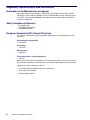
Declaration of the Manufacturer or Importer . . . . . . . . . . . . . . . . . . . . . . . . . . . . . . .
Safety Compliance Statement . . . . . . . . . . . . . . . . . . . . . . . . . . . . . . . . . . . . . . . . . . .
European Community (EC) Council Directives . . . . . . . . . . . . . . . . . . . . . . . . . . . . .
Electromagnetic Compatibility . . . . . . . . . . . . . . . . . . . . . . . . . . . . . . . . . . . . . .
Low Voltage . . . . . . . . . . . . . . . . . . . . . . . . . . . . . . . . . . . . . . . . . . . . . . . . . . . . . .
EC Conformity . . . . . . . . . . . . . . . . . . . . . . . . . . . . . . . . . . . . . . . . . . . . . . . . . . .
Telecommunications Terminal Equipment . . . . . . . . . . . . . . . . . . . . . . . . . . . .
Federal Communications Commission (FCC) Statement . . . . . . . . . . . . . . . . . . . .
FCC Declaration of Conformity . . . . . . . . . . . . . . . . . . . . . . . . . . . . . . . . . . . . . . . . . .
Canadian Compliance Statement (Industry Canada) . . . . . . . . . . . . . . . . . . . . . . .
Electromagnetic Compatibility . . . . . . . . . . . . . . . . . . . . . . . . . . . . . . . . . . . . . .
Laser Compliance Notice . . . . . . . . . . . . . . . . . . . . . . . . . . . . . . . . . . . . . . . . . . . . . . .
Definition of Safety Notices . . . . . . . . . . . . . . . . . . . . . . . . . . . . . . . . . . . . . . . . . . . . . . . .
Electrical Safety . . . . . . . . . . . . . . . . . . . . . . . . . . . . . . . . . . . . . . . . . . . . . . . . . . . . . . . . .
Laser Safety Information . . . . . . . . . . . . . . . . . . . . . . . . . . . . . . . . . . . . . . . . . . . . . . . . . .
Data Integrity and Verification . . . . . . . . . . . . . . . . . . . . . . . . . . . . . . . . . . . . . . . . . . . . .
Presentation . . . . . . . . . . . . . . . . . . . . . . . . . . . . . . . . . . . . . . . . . . . . . . . . . . . . . . . . . . . .
Configuration Examples . . . . . . . . . . . . . . . . . . . . . . . . . . . . . . . . . . . . . . . . . . . . . . . . . .
Important Safety Instructions . . . . . . . . . . . . . . . . . . . . . . . . . . . . . . . . . . . . . . . . . . . . . .
Checking Power Cords . . . . . . . . . . . . . . . . . . . . . . . . . . . . . . . . . . . . . . . . . . . . . . . . . . .
Delivery . . . . . . . . . . . . . . . . . . . . . . . . . . . . . . . . . . . . . . . . . . . . . . . . . . . . . . . . . . . . . . . .
Connections and Controls . . . . . . . . . . . . . . . . . . . . . . . . . . . . . . . . . . . . . . . . . . . . . . . . .
Connecting the Monitor, Keyboard, and Mouse . . . . . . . . . . . . . . . . . . . . . . . . . . . . . .
Powering On the Server for the First Time . . . . . . . . . . . . . . . . . . . . . . . . . . . . . . . . . . .
Mounting the DVD/CD–RW Device . . . . . . . . . . . . . . . . . . . . . . . . . . . . . . . . . . . . . . . . .
The NovaScale 4040 Resource CD . . . . . . . . . . . . . . . . . . . . . . . . . . . . . . . . . . . . . . . .
The NovasScale 4040 User’s Guide . . . . . . . . . . . . . . . . . . . . . . . . . . . . . . . . . . . . . . . .
AZERTY/QWERTY Keyboard Lookup Table . . . . . . . . . . . . . . . . . . . . . . . . . . . . . . . . .
NovaScale 4040 Server Cabinet Specifications . . . . . . . . . . . . . . . . . . . . . . . . . . . . . .
NovaScale 4040 Server CPU Drawer Specifications . . . . . . . . . . . . . . . . . . . . . . . . . .
Warnings . . . . . . . . . . . . . . . . . . . . . . . . . . . . . . . . . . . . . . . . . . . . . . . . . . . . . . . . . . . . . . .
WARNING: English (USA) . . . . . . . . . . . . . . . . . . . . . . . . . . . . . . . . . . . . . . . . . . . . .
AVERTISSEMENTS : Français . . . . . . . . . . . . . . . . . . . . . . . . . . . . . . . . . . . . . . . . .
WARNUNG: Deutsch . . . . . . . . . . . . . . . . . . . . . . . . . . . . . . . . . . . . . . . . . . . . . . . . . .
AVVERTENZA: Italiano . . . . . . . . . . . . . . . . . . . . . . . . . . . . . . . . . . . . . . . . . . . . . . . .
ADVERTENCIA: Español . . . . . . . . . . . . . . . . . . . . . . . . . . . . . . . . . . . . . . . . . . . . . . .
NovaScale 4040 Quick Start Guide
5
5
5
5
5
5
5
5
6
6
6
6
6
7
7
8
8
9
10
11
12
13
14
16
17
18
18
18
19
20
22
23
23
25
27
29
31
3
4
List of Figures
Figure 1. 19” / 19U and 19” / 36U cabinets . . . . . . . . . . . . . . . . . . . . . . . . . . . . . . . . . .
Figure 2. 36U cabinet configuration (example) . . . . . . . . . . . . . . . . . . . . . . . . . . . . . . .
Figure 3. 19U cabinet configuration (example) . . . . . . . . . . . . . . . . . . . . . . . . . . . . . . .
Figure 4. NovaScale 4040 Server Front View . . . . . . . . . . . . . . . . . . . . . . . . . . . . . . . .
Figure 5. NovaScale 4040 Server Peripheral Bay Module . . . . . . . . . . . . . . . . . . . . .
Figure 6. NovaScale 4040 Server Control Panel Status Lights . . . . . . . . . . . . . . . . .
Figure 7. NovaScale 4040 Server Rear Panel . . . . . . . . . . . . . . . . . . . . . . . . . . . . . . .
Figure 8. AZERTY keyboard . . . . . . . . . . . . . . . . . . . . . . . . . . . . . . . . . . . . . . . . . . . . . .
Figure 9. QWERTY keyboard . . . . . . . . . . . . . . . . . . . . . . . . . . . . . . . . . . . . . . . . . . . . . .
9
10
10
14
14
15
16
19
19
List of Tables
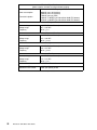
Table 1. NovaScale 4040 Server Control Panel Status Lights . . . . . . . . . . . . . . . . . .
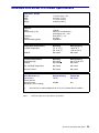
Table 2. NovaScale 4040 Server cabinet specifications . . . . . . . . . . . . . . . . . . . . . . .
Table 3. NovaScale 4040 Server CPU drawer specifications . . . . . . . . . . . . . . . . . . .
15
21
22
NovaScale 4040 Quick Start Guide
NovaScale 4040 Quick Start Guide
5
Regulatory Specifications and Disclaimers
Declaration of the Manufacturer or Importer
We hereby certify that this product is in compliance with European Union EMC Directive
89/336/EEC, using standards EN55022 (Class A) and EN55024 and Low Voltage Directive
73/23/EEC, using standard EN60950. The product has been marked with the CE Mark to
illustrate its compliance.
Safety Compliance Statement
• UL 60950 (USA)
• IEC 60950 (International)
• CSA 60950 (Canada)
European Community (EC) Council Directives
This product is in conformity with the protection requirements of the following EC Council
Directives:
Electromagnetic Compatibility
• 89/336/EEC
Low Voltage
• 73/23/EEC
EC Conformity
• 93/68/EEC
Telecommunications Terminal Equipment
• 199/5/EC
Neither the provider nor the manufacturer can accept responsibility for any failure to satisfy
the protection requirements resulting from a non-recommended modification of the product.
Compliance with these directives requires:
• an EC declaration of conformity from the manufacturer
• an EC label on the product
• technical documentation
6
NovaScale 4040 Quick Start Guide
Federal Communications Commission (FCC) Statement
Note:
This equipment has been tested and found to comply with the limits for a Class A digital
device, pursuant to Part 15 of the FCC Rules. These limits are designed to provide
reasonable protection against harmful interference when the equipment is operated in a
commercial environment. This equipment generates, uses, and can radiate radio frequency
energy and, if not installed and used in accordance with the instruction manual, may cause
harmful interference to radio communications. Operation of this equipment in a residential
area is likely to cause harmful interference in which case the user will be required to correct
the interference at his own expense.
Properly shielded and grounded cables and connectors must be used in order to meet FCC
emission limits. Neither the provider nor the manufacturer are responsible for any radio or
television interference caused by using other than recommended cables and connectors or
by unauthorized changes or modifications to this equipment. Unauthorized changes or
modifications could void the user’s authority to operate the equipment.
Any changes or modifications not expressly approved by the grantee of this device could
void the user’s authority to operate the equipment. The customer is responsible for ensuring
compliance of the modified product.
FCC Declaration of Conformity
This device complies with Part 15 of the FCC Rules. Operation is subject to the following
two conditions: (1) this device may not cause harmful interference, and (2) this device must
accept any interference received, including interference that may cause undesired
operation.
Canadian Compliance Statement (Industry Canada)
This Class A digital apparatus meets all requirements of the Canadian Interference Causing
Equipment Regulations.
Cet appareil numérique de la classe A est conforme à la norme NMB–003 du Canada.
This product is in conformity with the protection requirements of the following standards:
Electromagnetic Compatibility
• ICES–003
• NMB–003
Laser Compliance Notice
This product that uses laser technology complies with Class 1 laser requirements.
A CLASS 1 LASER PRODUCT label is located on the laser device.
Class 1 Laser Product
Luokan 1 Laserlaite
Klasse 1 Laser Apparat
Laser Klasse 1
NovaScale 4040 Quick Start Guide
7
Definition of Safety Notices
DANGER
A Danger notice indicates the presence of a hazard that has the potential of causing
death or serious personal injury.
CAUTION:
A Caution notice indicates the presence of a hazard that has the potential of causing
moderate or minor personal injury.
Warning:
A Warning notice indicates an action that could cause damage to a program, device,
system, or data.
Electrical Safety
The following safety instructions shall be observed when connecting or disconnecting
devices to the system.
DANGER
The Customer is responsible for ensuring that the AC electricity supply is compliant
with national and local recommendations, regulations, standards and codes of
practice.
An incorrectly wired and grounded electrical outlet may place hazardous voltage on
metal parts of the system or the devices that attach to the system and result in an
electrical shock.
It is mandatory to remove power cables from electrical outlets before relocating the
system.
CAUTION:
This unit has more than one power supply cable. Follow procedures for removal of
power from the system when directed.
8
NovaScale 4040 Quick Start Guide
Laser Safety Information
The optical drive in this system unit is a classified as a Class 1 level Laser product. The
optical drive has a label that identifies its classification.
The optical drive in this system unit is certified in the U.S. to conform to the requirements of
the Department of Health and Human Services 21 Code of Federal Regulations (DHHS 21
CFR) Subchapter J for Class 1 laser products. Elsewhere, the drive is certified to conform to
the requirements of the International Electrotechnical Commission (IEC) 60825–1: 2001 and
CENELEC EN 60825–1: 1994 for Class 1 laser products.
CAUTION:
Invisible laser radiation when open. Do not stare into beam or view directly with
optical instruments.
Class 1 Laser products are not considered to be hazardous. The optical drive contains
internally a Class 3B gallium–arsenide laser that is nominally 30 milliwatts at 830
nanometers. The design incorporates a combination of enclosures, electronics, and
redundant interlocks such that there is no exposure to laser radiation above a Class 1 level
during normal operation, user maintenance, or servicing conditions.
Data Integrity and Verification
Warning:
Bull NovaScale Servers are designed to reduce the risk of undetected data corruption
or loss. However, if unplanned outages or system failures occur, users are strongly
advised to check the accuracy of the operations performed and the data saved or
transmitted by the system at the time of outage or failure.
NovaScale 4040 Quick Start Guide
9
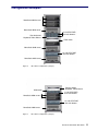
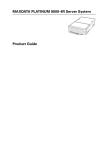
Presentation
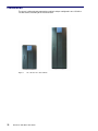
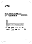
The server is delivered rack–mounted, pre–cabled and pre–configured in one 19”/19U or
19”/36U cabinet, according to the version chosen.
Figure 1.
10
19” / 19U and 19” / 36U cabinets
NovaScale 4040 Quick Start Guide
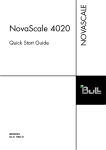
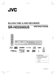
Configuration Examples
NovaScale 4020 servers
NovaScale 4040 server
Console drawer
Keyboard, Video, Mouse
8–slot SCSI RAID
disk rack drawers
KVM switch
NovaScale 4040 server
14–slot SCSI RAID
disk rack drawer
NovaScale 4040 server
Figure 2.
36U cabinet configuration (example)
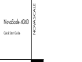
KVM switch
Console drawer
Keyboard, Video, Mouse
8–slot SCSI RAID
disk rack drawers
NovaScale 4020 servers
14–slot SCSI RAID
disk rack drawer
NovaScale 4040 server
Figure 3.
19U cabinet configuration (example)
NovaScale 4040 Quick Start Guide
11
Important Safety Instructions
Before proceeding to install the server, read all caution and safety statements at the end of
this document.
CAUTION:
Electrostatic discharge (ESD) can damage disk drives, add–in cards, and other parts.
This server can withstand normal levels of environmental ESD. Wear an anti–static
wrist strap attached to chassis ground of the server (i.e. any unpainted metal surface)
when handling components.
CAUTION:
Grounded outlet:
Ensure that the power service connection is through a properly grounded outlet.
Warning:
The following instructions are to be complied with for all rack–mounted servers:
Main AC power disconnects:
You are responsible for installing an AC power disconnect for the entire cabinet.
This main disconnect must be readily accessible, and it must be labeled as
controlling power to the entire cabinet and not just to the server(s).
Grounding the cabinet:
To avoid the potential for an electrical shock hazard, you must provide three–wire
safety–grounding for the cabinet and its contents.
Overcurrent protection:
Each server is designed for an AC line voltage source with up to 20 amperes of
overcurrent protection. If the power system for the cabinet is installed on a branch
circuit with more than 20 amperes of protection, you must provide supplemental
protection for the server.
12
NovaScale 4040 Quick Start Guide
Checking Power Cords
Warning:
The Power button on the server control panel does not completely remove AC power.
To completely remove AC power from the server, you must unplug all AC power
cords from the server or from the wall outlet.
Warning:
Do not attempt to modify or use an AC power cord that is not the exact type required.
Rack–mounted servers:
1. Server power units must be connected to the PDU(s) (Power Distribution Unit(s))
located inside the cabinet. Connect server power cords to the outlets at the front
of the PDU(s). Do NOT use the outlets at the rear of the PDU(s).
2. Connect the PDU(s) to the site power supply with the power cord(s) provided with
the PDU(s).
Desktop servers:
1. U.S. / Canada:
Cords must be UL Listed/CSA Certified, 16/3, 75C type, VW–1, SJT/SVT, with NEMA
5–15P or NEMA 6–15P attachment plug and IEC 320 C13 input power connector
rated 15 amps.
Outside U.S. / Canada:
Cords must be flexible harmonized (<HAR>) rated 250V, 1.0 mm minimum
conductor size with IEC 320 C13 input power connector and rated for no less than
10 amps.
2. AC attachment connector:
The AC wall attachment plug should be a three conductor grounding type in
compliance with the national and regional standards in force :
– Nominal voltage: 125 V / 250 V
– Nominal amperage: 15 A
The AC wall attachment plug must bear an accepted safety agency certification
mark for the specific country or country.
3. Input power connector, server end:
The connectors that plug into the AC receptacles on the server must be an IEC
320, sheet C13 type female connectors :
– Nominal voltage: 125 V / 250 V
– Nominal amperage: 15 A
Note:
Surge Suppressor Recommendations:
In geographic regions that are susceptible to electrical storms, we highly recommend that
you plug the server into a surge suppressor.
EMI Information:
For information about complying with electromagnetic interference regulations, see
“Electromagnetic Compatibility” in the NovaScale User’s Guide.
NovaScale 4040 Quick Start Guide
13
Delivery
Site preparation must be completed by the pre–arranged delivery date. Any delay due to
non–completion of the site by the pre–arranged date will be considered as the Customer’s
responsibility. See the NovaScale Series Site Preparation Guide.
The server is delivered 24 hours in advance of the scheduled installation date. On arrival,
the server must be placed, in its packing, in the Computer Room so that it reaches room
temperature before powering up (optimum operating temperature = 22° C + 3° C,
hygrometry = 50% + 5%).
CAUTION:
It is mandatory for the server to be transported vertically. The server cabinet is
extremely heavy and requires the use of an elevator. The Data Processing Site
manager must allocate enough personnel to ensure safe handling.
14
NovaScale 4040 Quick Start Guide
Connections and Controls
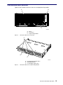
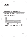
Figures 4 and 5 show the NovaScale 4040 Server and peripheral bay module.
B
A
C
OM12885
Figure 4.
A Bezel
B Front Panel
C Peripheral Bay Module
NovaScale 4040 Server Front View
A
B
C
OM12905
Figure 5.
A Hot swap SCSI hard disk drives
B DVD/CD–ROM drive
C LS–240 floppy diskette drive
NovaScale 4040 Server Peripheral Bay Module
NovaScale 4040 Quick Start Guide
15
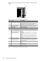
Figure 6 shows server drawer control panel status lights for fans, hard drives and power
supplies.
A
E
B
C
D
F
G
H
I
OM12886
Figure 6.
NovaScale 4040 Server Control Panel Status Lights
Item
Feature
Switches
A
System ID Switch
B
Assert SDINT (System Diagnostic Interrupt) Switch
C
Reset switch
D
Power switch
LED Indicators
E
System ID (Blinking or Solid
Blue). The system ID LEDs
are located inside the system
ID switch on the front panel,
and on the back panel.
F
Main Power (Solid Green,
Blinking Green indicates the
system is in sleep mode.)
G
Power Fault (Solid Amber)
H
Cooling Fault (Solid Amber)
I
General Fault (Solid amber)
Table 1.
16
Description
Toggle switch for blue System ID LEDs (the front panel
system ID LED is located inside the system ID switch).
See E below for description of LED operation.
Asserts SDINT. This switch is accessible through a
small opening and requires a narrow tool to activate.
Resets the system.
Toggles system power.
Identifies the system. The system ID is activated either
by the system ID switch or through server management
software.
Pressing the system ID switch once turns on the LEDs
solid blue
Press the system ID switch again, the solid blue LEDs
turn off
Remove activation – LEDs turn on blinking for 4 minutes (max). LEDs cannot be turned off by pressing the
switch.
A continuously lit LED indicates the presence of DC
power in the system. The LED goes out when the power is turned off or the power source is disrupted. Off
indicates power off.
Indicates any system power faults. Off indicates power
is OK.
Indicates any system cooling faults. Off indicates system cooling is OK.
Indicates a system failure. Off indicates system is OK.
NovaScale 4040 Server Control Panel Status Lights
NovaScale 4040 Quick Start Guide
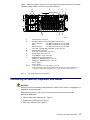
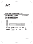
Figure 7 shows the features found on the server drawer rear panel including the I/O module,
the power supply modules, and user–accessible connectors.
A
B
C
D
G
F
E
J
I
H
OM12888
A
B
AC input power connectors
PCI Slots (All slots support hot plug PCI add–in cards)1
Slots 1 through 4
100–MHz, 64–bit PCI–X slot, half length
Slot 5
100–MHz, 64–bit PCI–X slot, full length
Slots 6 through 8
133–MHz, 64–bit PCI–X slot, full length
Video port, standard VGA compatible, 15–pin connector
External SCSI connector2
Serial port, 9–pin RS–232 connector3
Ethernet port, RJ45 connector
Four USB ports, 4–pin connectors
ICMB connectors in/out (optional)
ICMB port 1, SEMCONN 6–pin connector
ICMB port 2, SEMCONN 6–pin connector
Power supply 2
Power supply 1
C
D
E
F
G
H
I
J
Notes:
Figure 7.
1. PCI slots support 3.3–V signal adapter cards only.
2. External SCSI bus supports both LVDS and SE signals via the external SCSI connector.
3. Emergency Management Port (EMP) access is provided via the shared serial port.
NovaScale 4040 Server Rear Panel
Connecting the Monitor, Keyboard, and Mouse
CAUTION:
Unplug server before connecting external devices, make sure the server is not plugged in or
equipment could be damaged.
Before powering on the server, you must connect these devices to the back of the
NovaScale 4040 Server.
1. Video monitor to the video port (C in Figure 7.)
2. Keyboard to a USB port (G in Figure 7.)
3. Mouse to a USB port (G in Figure 7.)
NovaScale 4040 Quick Start Guide
17
Powering On the Server for the First Time
The first time you power on the server, you need to enter the BIOS Setup Utility and set the
correct date and time values. The server then executes its Power–On Self Test (POST)
sequence and passes control to the Boot Manager. From the Boot Manager, you can mount
the DVD/CD–RW device to block zero and then load the operating system.
For further information about the Boot Manager, the EFI Shell, and the BIOS Setup Utility,
refer to the NovaScale 4040 User’s Guide.
Warning:
The EFI shell can only manage QWERTY keyboards. If you have an AZERTY
keyboard, please refer to the AZERTY/QWERTY keyboard lookup table on page 20.
Follow these steps to power on the NovaScale 4040 Server for the first time:
1. Ensure that all external devices are connected (monitor, keyboard, mouse, disk racks,
printers, etc).
2. Connect the server power supply cable(s) to the power supply outlet.
3. Power on the video monitor.
4. Press the Power button on the server drawer control panels (F in Figure 6. Server Draw
Control Panel). The server fans start up and POST begins.
5. When POST displays the message:
“Hit <F2> if you want to run SETUP,”
enter <F2>. The system will enter the BIOS Setup Utility.
If you see a prompt asking for a system password, press the <ENTER> key for direct
access to the BIOS Setup Utility.
6. From the BIOS Setup Utility Main menu, use the arrow keys to move the cursor down to
system date and time selections. Position the cursor over the date and time values and
enter appropriate values. Use the <tab> key to move within the date and time fields.
7. Use the arrow key to access the Exit menu and select Save changes and exit the
BIOS Setup Utility. After you exit the utility, the boot procedure resumes. You can
monitor the remainder of the boot progress on the video display.
Note:
POST checks the processors, memory, keyboard, and most installed peripheral devices.
During the memory test, POST displays the amount of memory it is able to access and test.
The length of time needed to test memory depends on the amount of memory installed.
POST is stored in flash memory.
8. The AMI* BIOS banner displays the loaded versions of the BIOS, PAL, SAL, and EFI.
9. The LSI* banner appears and indicates the recognized drives. Note that a Platform
Configuration EFI based configuration utility is required to enter the LSI SCSI utility. The
LSI* SCSI utility enables you to manage and configure the server’s SCSI devices.
10.POST concludes and passes control to the Boot Manager.
11. From the Boot Manager, you can use the arrow keys to highlight and select the option
that invokes the EFI Shell or the Boot Maintenance Menu. Booting to the EFI Shell
causes the following prompt to appear:
Shell>
12.Mount the DVD/CD–RW device as block zero. See “Mounting the DVD/CD–RW Device”
below.
18
NovaScale 4040 Quick Start Guide
13.Boot the operating system that you want to run on the server.
Mounting the DVD/CD–RW Device
You must mount the DVD–CD–RW drive before you can use it to read media:
1. Ensure that you are in the EFI Shell. You should see the following prompt:
Shell>
2. For the mount command in the next step to work, the drive must be loaded with media.
3. At the shell prompt, enter the following command:
mount –r
The media in the DVD/CD–RW drive is mapped to one of the file systems, i.e., FS0:, FS1:,
FS2. Change to the appropriate file system and enter the following command:
ls
The NovaScale 4040 Resource CD
The NovaScale 4040 Resource CD has the following contents: Utilities (SDRViewert,
SELViewert, FRUSDR Loadert, System Maintenance Utility (SMU), EFI Platform
Diagnostics), the NovaScale 4040 Quick Start Guide (this guide), the NovaScale 4040
User’s Guide and Adobet Acrobat Reader.
The Resource CD comes with a menu driven program that can be used for the following:
1. Create a removable media containing utilities, service partition and diagnostics.
2. Install EFI* Service Partition. The EFI service partition supports remote access to the
NovaScale 4040 Server, via modem or LAN, for the purpose of executing
configuration/setup utilities and diagnostics.
3. Run EFI–based utilities.
How to invoke the Resource CD menu.
1. Insert the Resource CD into the DVD/CD–RW drive before booting to EFI Shell.
2. Boot the system into EFI Shell; the EFI CD Menu program will launch automatically. If
the EFI CD Menu program does not launch in the EFI Shell, mount and map to the CD
drive, type ‘startup’ and press <Enter> to launch the EFI CD Menu.
3. Arrow key over to the Utilities and select the utility you want to run.
The NovasScale 4040 User’s Guide
The NovaScale 4040 User’s Guide comes as a single .PDF file shipped on the resource
CD. You can use Adobet Acrobat Reader to view the guide.
NovaScale 4040 Quick Start Guide
19
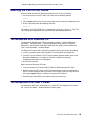
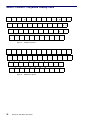
AZERTY/QWERTY Keyboard Lookup Table
1
2
3
&
é
~ ”
A
Z
Q
E
S
>
4
# ’
R
D
W
5
6
7
8
9
0
°
+
{ (
[ –
| è
‘ _
\ ç
^ à
@ )
] =
T
F
X
Y
G
C
U
H
V
I
J
B
K
N
<
Figure 8.
O
P
L
¨
£
^
$
M
¤
%
µ
ù
*
?
.
/
§
,
;
:
!
AZERTY keyboard
~
!
@
#
$
%
^
&
*
(
)
_
+
‘
1
2
3
4
5
6
7
8
9
0
–
=
Q
W
A
E
S
Z
R
D
X
Figure 9.
20
}
T
F
Y
G
C
V
U
H
B
QWERTY keyboard
NovaScale 4040 Quick Start Guide
I
J
O
K
N
M
P
L
{
}
|
[
]
\
:
”
;
’
<
>
?
,
.
/
NovaScale 4040 Server Cabinet Specifications
NovaScale 4040 servers are delivered rack–mounted in a 19U or 36 U cabinet.
36U Cabinet Dimensions / Weight
Unpacked
Height: 174.0 cm (68.5 in)
Width: 65.0 cm (25.6 in)
Depth: 113.6 cm (44.7 in)
Weight (empty): 225 kg (496 lb)
Weight (full): 680 kg (1280 lb)
Packed
Height: 200.5 cm (80.7 in)
Width: 80.0 cm (31.5 in)
Depth: 120.0 cm (47.2 in)
Weight (empty): 255 kg (562 lb)
Weight (full): 610 kg (1345 lb)
19U Cabinet Dimensions / Weight
Unpacked
Height: 100.0 cm (39.4 in)
Width: 65.0 cm (25.6 in)
Depth: 113.6 cm (44.7 in)
Weight (empty): 200 kg (440 lb)
Weight (full): 390 kg (860 lb)
Packed
Height: 118.0 cm (46.49 in)
Width: 80.0 cm (31.5 in)
Depth: 120.0 cm (47.2 in)
Weight (empty): 230 kg (507 lb)
Weight (full): 420 kg (927 lb)
Service Clearance
Front
Rear
Side (left and right)
150 cm
100 cm
100 cm
Power Cables
AC (20A)
Cable type
Connector type
1 per PDU
3 x 4mm / AWG # 12 (US)
C22 Appliance Coupler
It is mandatory for power lines and terminal boxes to be located within the immediate vicinity of the system and to be easily accessible. Each power line must be
connected to a separate, independent electrical panel and bipolar circuit breaker.
The PDU requires an extra cable length of 1.5 meters for connection inside the cabinet.
NovaScale 4040 Quick Start Guide
21
Electrical Specifications
(power supplies are auto–sensing and auto–ranging)
Current draw
Power consumption
Thermal dissipation
24 A max. at 240 VAC input per PDU
8800 VA (max. 36U cabinet)
5500 VA (max. 19U cabinet)
5700 VA (max. per PDU)
1500 VA / 5100 BTU (per NovaScale 4040 CPU drawer)
650 VA / 2300 BTU (per NovaScale 4020 CPU drawer)
Europe
Nominal voltage
Voltage range
Frequency
230 VAC (Phase / Neutral)
207 – 244 VAC
50 Hz 1%
United States of America
Nominal voltage
Voltage range
Frequency
208 VAC (Phase / Neutral)
182 – 229 VAC
60 Hz 0.3%
Japan
Nominal voltage
Voltage range
Frequency
200 VAC (Phase / Neutral)
188 – 212 VAC
60 Hz 0.2%
Brazil
Nominal voltage
Voltage range
Frequency
220 VAC (Phase / Neutral)
212 – 231 VAC
60 Hz 2%
Breaker Protection
Mains power PDU
Maximum inrush current
Table 2.
22
20A Curve C
210A / per quarter period
NovaScale 4040 Server cabinet specifications
NovaScale 4040 Quick Start Guide
NovaScale 4040 Server CPU Drawer Specifications
Dimensions / Weight
Height
Width
Depth
Weight
Electrical
Power
Voltage range (V ac)
Frequency
current
Thermal output (typical)
Temperature Requirements
Dry Bulb Temperature
17.53 cm (6.9 in, 4U)
44.45 cm (17.5 in)
71.12 cm (28.0 in)
48.08 kg (106 lbs)
1500 VA
200 V ac to 240 nominal,
autoranging +6%, –10%
50 to 60 Hz 5%
6.4 amps
6100 Btu/hr
Gradient
Operating
10 to 35_C
(50 to 95_F)
Not stated
Non–Operating
–40 to 70_C
(–40 to 158_F)
Not stated
Humidity Requirements
(noncondensing)
Gradient
Operating
Not stated
Not stated
Non–Operating
90% at 25 to 35°C
Not stated
Max. Wet Bulb Temperature
Not stated
Not stated
Moisture Content
Not stated
Not stated
Noise Emissions (1)
System Running
System Idle
Sound Power
(Dome method)
Sound Pressure
(Bystander, Floor–standing)
7.0 BA
Not stated
60 dBA
N/A
(1)
Table 3.
Acoustic tests at room temperature of 28°C (82°F) without failure condition.
NovaScale 4040 Server CPU drawer specifications
NovaScale 4040 Quick Start Guide
23
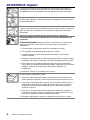
Warnings
WARNING: English (USA)
The power supply in this product contains no user–serviceable parts. There may be
more than one supply in this product. Refer servicing only to qualified personnel.
Do not attempt to modify or use the supplied AC power cord if it is not the exact type
required. A product might be equipped with more than one AC power cord.
The power button on the system does not turn off all system AC power. To remove
all AC power from the system, you must unplug each AC power cord from the wall
outlet or power supply.
To avoid injury from electrical and mechanical hazards, chassis covers
should only be removed by qualified service personnel.
SAFETY STEPS: Whenever you remove the chassis covers to access the inside of
the system, follow these steps:
4. Turn off all peripheral devices connected to the system.
5. Turn off the system by pressing the power button.
6. Unplug all AC power cords from the system or from wall outlets.
7. Label and disconnect all telecommunication cables and all other cables
connected to I/O connectors or ports on the back of the system.
8. Provide some electrostatic discharge (ESD) protection by wearing an anti–static
wrist strap attached to chassis ground of the system—any unpainted metal
surface—when handling components.
9. Do not operate the system with the chassis covers removed.
After you have completed the six SAFETY steps above, remove the covers as
follows:
1. To open the top back cover, push the sliding latches on the top of the cover and
pull the cover toward the back of the chassis.
2. To remove the top back cover, continue to slide the cover toward the back of the
chassis until it reaches the end–stops. Press the latch on the left rail slide and
pull the cover until it clears the chassis.
3. To remove the top front cover, loosen the two captive screws on either side of
the cover, slide the cover toward the front of the chassis until it stops, then lift the
cover off.
4. Always replace the covers before operating the system.
24
NovaScale 4040 Quick Start Guide
For proper cooling and airflow, unless hot swapping PCI cards or fans, always
reinstall the chassis covers before turning on the system. Operating the system
without the covers in place can damage system parts. To install the covers:
1. Check first to make sure you have not left loose tools or parts inside the system.
2. Check that cables, add–in boards, and other components are properly installed.
3. To replace the top back cover, slide the two bearing cages on the back top cover
all the way to the end of the slides.
4. Place the top cover on the cover slides and push the cover into place.
5. To replace the top front cover, attach the back edge of the front top cover to the
chassis, lower the front edge of the cover onto the chassis, then push the cover
into place.
6. Tighten the two captive screws on either side of the cover.
7. Connect all external cables and the AC power cord(s) to the system.
A microprocessor and heat sink might be hot if the system has been running. Also,
there might be sharp pins and edges on some board and chassis parts. Contact
should be made with care. Consider wearing protective gloves.
Danger of explosion if the battery is incorrectly replaced. Replace only with the
same or equivalent type recommended by the equipment manufacturer. Discard
used batteries according to manufacturer’s instructions.
The system is designed to operate in a typical office environment. Choose a site
that is:
• Clean and free of airborne particles (other than normal room dust).
• Well–ventilated and away from sources of heat including direct sunlight.
• Away from sources of vibration or physical shock.
• Isolated from strong electromagnetic fields produced by electrical devices.
• Protected when in regions that are susceptible to electrical storms. We
recommend you plug your system into a surge suppresser and disconnect
telecommunication lines to your modem during an electrical storm.
• Provided with a properly grounded wall outlet.
• Provided with sufficient space to access the power supply cords, because they
serve as the product’s main power disconnect.
Servers can be too heavy for a single person to lift or move safely. Depending on
the server, use two people or a mechanical assist to lift or move the server.
NovaScale 4040 Quick Start Guide
25
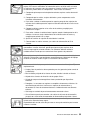
AVERTISSEMENTS : Français
Le bloc d’alimentation de ce produit ne contient aucune pièce pouvant être réparée
par l’utilisateur. Ce produit peut contenir plusieurs blocs d’alimentation. Veuillez
contacter un technicien qualifié en cas de problème.
Ne pas essayer d’utiliser ni de modifier le câble d’alimentation CA fourni, s’il ne
correspond pas exactement au type requis. Un produit peut être équipé de plus d’un
câble d’alimentation CA.
Le bouton d’alimentation du système n’éteint pas toutes les alimentations CA du
système. Pour mettre complètement le système hors tension, vous devez
débrancher chaque cordon d’alimentation CA de sa prise.
Pour éviter toute lésion à la suite de risques électriques et mécaniques, les
panneaux du châssis ne doivent être démontés que par un personnel qualifié.
CONSIGNES DE SÉCURITÉ : Lorsque vous retirez les panneaux du châssis pour
accéder à l’intérieur du système, suivez les étapes ci–dessous :
1. Mettez hors tension tous les périphériques connectés au système.
2. Mettez hors tension le système en appuyant sur le bouton d’alimentation.
3. Débranchez tous les cordons d’alimentation CA du système ou des prises
murales.
4. Identifiez et déconnectez tous les câbles de télécommunications et tous les
autres câbles reliés aux connecteurs E/S ou aux ports derrière le système.
5. Pour prévenir les décharges électrostatiques lorsque vous touchez aux
composants, portez un bracelet antistatique et reliez–le à la masse du système
(toute surface métallique non peinte du boîtier).
6. Ne faites pas fonctionner le système si les panneaux du châssis sont enlevés.
Une fois que vous avez effectué les six étapes de SÉCURITÉ, retirez les panneaux
comme indiqué ci–dessous :
1. Pour ouvrir le panneau arrière supérieur, poussez sur les loquets coulissants
placés sur le dessus du panneau et tirez ce dernier vers l’arrière du châssis.
2. Pour retirer le panneau arrière supérieur, continuez à le faire glisser vers l’arrière
du châssis, jusqu’à ce qu’il atteigne les butées. Appuyez sur le loquet du rail
gauche et retirez le panneau du châssis.
3. Pour retirer le panneau avant supérieur, desserrez les deux vis imperdables de
chaque côté du panneau, faites glisser ce dernier vers l’avant du châssis au
maximum, puis soulevez–le.
4. Remettez toujours le panneau en place avant de lancer le système.
26
NovaScale 4040 Quick Start Guide
Pour un refroidissement et une circulation d’air efficaces, remettez toujours en place
le panneau avant d’utiliser le système, sauf si vous disposez de cartes PCI ou de
ventilateurs échangeables à chaud. Le fonctionnement du système sans les
panneaux risque d’endommager ses composants. Pour installer les panneaux :
1. Assurez–vous en premier lieu de ne pas avoir oublié d’outils ou de composants
à l’intérieur du système.
2. Vérifiez que les câbles, les cartes additionnelles et autres composants sont
correctement installés.
3. Pour remettre en place le panneau supérieur arrière, faites glisser les cages à
roulement du panneau jusqu’au bout des glissières.
4. Placez le panneau supérieur sur les glissières puis faites–le glisser jusqu’à la
position fermée.
5. Pour remettre en place le panneau avant supérieur, accrochez la partie arrière
du panneau sur le châssis, faites basculer ce dernier vers l’avant vers le châssis,
puis poussez pour le bloquer en position fermée.
6. Serrez les deux vis imperdables de chaque côté du panneau.
7. Connectez tous les câbles externes et le ou les cordons d’alimentation au
système.
Le microprocesseur et le dissipateur de chaleur peuvent être chauds si le système a
été sous tension. Faites également attention aux broches aiguës des cartes et aux
bords tranchants du capot. Les contacts doivent être établis avec soin. L’usage de
gants de protection est conseillé.
Danger d’explosion si la batterie n’est pas remontée correctement. Remplacer
uniquement par une pile du même type ou de type équivalent recommandé par le
fabricant. Débarrassez–vous des piles usagées conformément aux instructions du
fabricant.
Le système a été conçu pour fonctionner dans un cadre de travail normal.
L’emplacement choisi doit être :
• Propre et dépourvu de poussières en suspension (sauf la poussière normale).
• Bien aéré et loin des sources de chaleur, y compris du soleil direct.
• À l’abri des chocs et des sources de vibration.
• Isolé des forts champs électromagnétiques générés par des appareils
électriques.
• Protégé s’il se trouve dans des régions sujettes aux orages magnétiques. Nous
vous recommandons de connecter votre système à un suppresseur de
surtension et de déconnecter les lignes de télécommunications de votre modem
pendant un orage magnétique.
• Muni d’une prise murale correctement mise à la terre.
• Suffisamment spacieux pour vous permettre d’accéder aux câbles d’alimentation
(ceux–ci étant le seul moyen de mettre le système hors tension).
Il se peut que les serveurs soient trop lourds pour qu’une seule personne puisse les
soulever et les déplacer en toute sécurité. En fonction du serveur, utilisez deux
personnes ou utilisez un équipement mécanique auxiliaire pour soulever ou
déplacer le serveur.
NovaScale 4040 Quick Start Guide
27
WARNUNG: Deutsch
Das Netzteil dieses Computers enthält keine wartungsbedürftigen Teile. Dieses
Produkt kann über mehrere Netzteile verfügen. Überlassen Sie Wartungsarbeiten
nur qualifizierten Fachleuten.
Versuchen Sie nicht, das mitgelieferte Netzkabel zu verändern oder einzusetzen,
wenn es nicht exakt dem benötigten Kabeltyp entspricht. Das Produkt kann über
mehrere Netzkabel verfügen.
Durch Ausschalten des Netzschalters wird die Wechselstromversorgung des
Systems
nicht unterbrochen. Um das System vom Netz zu trennen, müssen Sie das
Netzkabel
aus der Steckdose oder vom Netzteil abziehen.
Vermeiden Sie Verletzungen aufgrund elektrischer oder mechanischer
Gefahren; lassen Sie daher den Gehäusedeckel nur von technisch
qualifiziertem Personal abnehmen.
SICHERHEITSHINWEISE: Beachten Sie beim Abnehmen der Gehäuseabdeckung
und Arbeiten im Inneren des Systems folgende Schritte:
1. Schalten Sie alle am System angeschlossenen Peripheriegeräte ab.
2. Drücken Sie den Netzschalter, um das System abzuschalten.
3. Ziehen Sie alle Wechselstromkabel vom System und den Steckdosen ab.
4. Kennzeichnen Sie alle Telekommunikationsleitungen und sonstigen Kabel an
den E/A–Steckern bzw. Anschlüssen an der Rückseite des Systems, und
trennen Sie diese vom Netz.
5. Um sich gegen elektrostatische Entladung zu schützen, sollten Sie eine
Antistatik–Manschette tragen, die Sie beim Arbeiten mit Komponenten zur
Erdung an einem beliebigen unlackierten Metallteil befestigen.
6. Nehmen Sie das System nicht ohne Abdeckung in Betrieb.
Nachdem Sie die sechs bereits beschriebenen Schritte zur SICHERHEIT befolgt
haben, können Sie die Abdeckung, wie im folgenden erläutert, abnehmen.
1. Zum Öffnen der oberen, rückwärtigen Abdeckung, drücken Sie die Verriegelung
oben an der Abdeckung und schieben die Abdeckung an das Ende des
Gehäuses.
2. Um die obere, rückwärtige Abdeckung abzunehmen, schieben Sie die
Abdeckung bis zum Anschlag an das Ende des Gehäuses. Drücken Sie die
Verriegelung der linken Schienenkomponente, und ziehen Sie die Abdeckung
vollständig vom Gehäuse ab.
3. Lösen Sie zum Abnehmen der oberen, vorderseitigen Abdeckung die beiden
unverlierbaren Schrauben an beiden Seiten der Abdeckung. Schieben Sie dann
die Abdeckung bis zum Anschlag Richtung Vorderseite des Gehäuses, und
nehmen Sie sie ab.
4. Bringen Sie die Abdeckung vor Inbetriebnahme des Systems wieder an.
28
NovaScale 4040 Quick Start Guide
Bringen Sie die Gehäuseabdeckung vor Inbetriebnahme wieder an, um
ordnungsgemäße Kühlung und Lüftung zu gewährleisten. Dies gilt nicht für das
Hot–Swapping von PCI–Karten oder Ventilatoren. Die Inbetriebnahme des Systems
ohne angebrachte Abdeckung kann zur Beschädigung von Systemkomponenten
führen. So bringen Sie die Abdeckung wieder an:
1. Vergewissern Sie sich zunächst, daß Sie keine Werkzeuge oder Teile im
Gehäuse vergessen haben.
2. Prüfen Sie, ob Kabel, Erweiterungskarten sowie weitere Komponenten
ordnungsgemäß angebracht sind.
3. Schieben Sie zur Anbringung der hinteren, rückwärtigen Abdeckung die beiden
Haltekomponenten bis zum Anschlag an das Ende der Schiene.
4. Legen Sie die obere Abdeckung in die Schienen ein, und schieben Sie die
Abdeckung in Position.
5. Bringen Sie dann die rückwärtige Kante der oberen, vorderseitigen Abdeckung
am Gehäuse an, senken Sie die vordere Kante der Abdeckung auf das
Gehäuse, und schieben Sie die Abdeckung in Position.
6. Ziehen Sie die zwei unverlierbaren Schrauben an beiden Seiten der Abdeckung
fest.
7. Schließen Sie wieder alle externen Kabel und Netzstecker an das System an.
Mikroprozessor und Kühlkörper können heiß sein, wenn das System längere Zeit
eingeschaltet war. Einige Platinen– und Gehäuseteile können scharfe Spitzen und
Kanten aufweisen. Gehen Sie auf jeden Fall mit Vorsicht heran. Das Tragen von
Schutzhandschuhen wird empfohlen.
Wird die Batterie unsachgemäß ausgewechselt, besteht Explosionsgefahr. Ersetzen
Sie die Batterie nur durch denselben oder einen gleichwertigen Batterietyp, der vom
Gerätehersteller empfohlen wird. Entsorgen Sie verbrauchte Batterien gemäß den
Herstellerempfehlungen.
Das System ist für den Betrieb innerhalb normaler Büroumgebungen geeignet. Der
Standort sollte folgende Anforderungen erfüllen:
• Saubere, möglichst staubfreie Umgebung.
• Gut belüftet und weit entfernt von Wärmequellen wie direkte Sonneneinstrahlung.
• Vibrations– und erschütterungsfreie Umgebung.
• Abgeschirmt von starken elektromagnetischen Feldern, die durch elektrische
Geräte erzeugt werden.
• Entsprechender Schutz bei Betrieb in gewittergefährdeten Gebieten. Es empfiehlt
sich, den Computer über einen Überspannungsschutz anzuschließen und die
Verbindung zwischen dem Modem und dem Telefonanschluß im Falle eines
Gewitters zu trennen.
• Ausgestattet mit einer ordnungsgemäß geerdeten Wandsteckdose.
• Sorgen Sie für ausreichend Platz, damit das Servernetzkabel problemlos erreicht
werden kann, da das Gerät nur über dieses Kabel vom Netz getrennt wird.
Um einen Server sicher anzuheben und zu bewegen ist eine Person nicht
ausreichend. Bewegen Sie den Server, je nach Größe, entweder zu zweit oder
mittels einer mechanischen Hilfe.
NovaScale 4040 Quick Start Guide
29
AVVERTENZA: Italiano
L’alimentatore contenuto nel computer non contiene parti riparabili dall’utente.
Questo prodotto può essere fornito con più alimentatori. Per l’assistenza fare
riferimento solo a personale qualificato.
Non tentare di modificare o utilizzare cavi di alimentazione in c.a. che non siano del
tipo prescritto. Un prodotto potrebbe contenere più di un cavo di alimentazione in
c.a.
L’interruttore di accensione del sistema non scollega tutta l’alimentazione in c.a. del
sistema. Per scollegare tutta l’alimentazione in c.a., è necessario disinserire ogni
cavo di alimentazione in c.a. dalla presa a muro o dall’alimentatore.
Per evitare incidenti elettrici e meccanici, i coperchi del telaio devono essere
rimossi da personale qualificato.
MISURE DI SICUREZZA: Nel caso sia necessario rimuovere i coperchi del telaio
per accedere alle parti interne del sistema, procedere nel seguente modo:
1. Spegnere tutte le periferiche collegate al sistema.
2. Spegnere il sistema premendo il pulsante di accensione.
3. Scollegare tutti i cavi di alimentazione in c.a. dal sistema o dalle prese a muro.
4. Apporre un’etichetta e scollegare tutti i cavi di telecomunicazione e i cavi
collegati ai connettori di I/O o alle porte sulla parte posteriore del sistema.
5. Assicurare un minimo di protezione da scariche elettrostatiche (ESD)
indossando un bracciale antistatico collegato a un componente metallico non
verniciato del telaio quando si maneggiano i componenti.
6. Non attivare il sistema nel caso in cui i coperchi del telaio siano stati rimossi.
Dopo aver effettuato le sei operazioni di SICUREZZA descritte in precedenza,
rimuovere i coperchi nel modo seguente:
1. Per aprire il coperchio superiore sul retro del sistema, premere le linguette di
chiusura sulla parte superiore del coperchio e tirare il coperchio verso la parte
posteriore del telaio.
2. Per rimuovere il coperchio superiore sul retro del sistema, continuare a far
scorrere il coperchio verso la parte posteriore del telaio fino a raggiungerne le
estremità. Premere la linguetta di chiusura sulla guida di scorrimento di sinistra
e tirare il coperchio fino a liberare il telaio.
3. Per rimuovere il coperchio frontale superiore, svitare le due viti su entrambi i lati
del coperchio, far scorrere il coperchio verso la parte frontale del telaio fino
all’arresto, quindi togliere il coperchio.
4. Riposizionare sempre i coperchi prima dell’utilizzo del sistema.
30
NovaScale 4040 Quick Start Guide
Per evitare che il sistema si surriscaldi e per garantire una ventilazione adeguata, in
assenza di schede PCI e ventole sostituibili a computer acceso, reinstallare sempre
i coperchi del telaio prima di attivare il sistema. Se si attiva il sistema senza aver
riposizionato i coperchi correttamente, alcune parti del sistema potrebbero risultare
danneggiate. Per installare i coperchi:
1. Verificare innanzitutto di non aver lasciato utensili o altre parti all’interno del
sistema.
2. Verificare che i cavi, le schede aggiuntive e gli altri componenti siano stati
installati correttamente.
3. Per riposizionare il coperchio superiore del retro del sistema, affiancare le due
gabbie cuscinetto sul coperchio superiore del retro fino a raggiungere l’estremità
delle guide di scorrimento.
4. Posizionare il coperchio superiore sulle guide di scorrimento del coperchio e
premere il coperchio fino a raggiungere la posizione corretta.
5. Per riposizionare il coperchio frontale superiore, collegare al telaio l’estremità
posteriore del coperchio frontale superiore, inserire l’estremità frontale del
coperchio sul telaio, quindi spingere il coperchio fino a raggiungere la posizione
corretta.
6. Stringere le due viti su entrambi i lati del coperchio.
7. Collegare tutti i cavi esterni e il cavo o i cavi di alimentazione in c.a. al sistema.
Se il sistema è stato in funzione, il microprocessore e il dissipatore di calore
potrebbero essere caldi. Inoltre su alcune parti della scheda e del telaio potrebbero
esserci piedini appuntiti e bordi taglienti. Prestare quindi molta attenzione nel
toccarli. Indossare guanti protettivi.
Se sostituita in modo errato, la batteria potrebbe esplodere. Sostituire le batterie
scariche solo con batterie originali o del tipo consigliato dal produttore
dell’apparecchiatura. Per lo smaltimento delle batterie usate attenersi alle istruzioni
del produttore.
Il sistema è concepito per l’utilizzo in ambienti adibiti a ufficio. Scegliere una
postazione con le caratteristiche riportate di seguito.
• Pulita, priva di particelle diverse dalla polvere normalmente presente
nell’ambiente di lavoro.
• Aerata e lontana da fonti di calore, compresa la luce solare diretta.
• Lontana da fonti di vibrazione o urti.
• Isolata da forti campi elettromagnetici prodotti da apparecchi elettrici.
• Protetta nelle regioni soggette a temporali. Durante un temporale, si consiglia di
collegare il sistema a un limitatore di corrente e di scollegare le linee di
telecomunicazione dal modem.
• La posizione prescelta deve essere dotata di una presa a muro con adeguata
messa a terra.
• Deve inoltre esserci sufficiente spazio per accedere ai cavi di alimentazione nel
caso sia necessario scollegare l’alimentazione principale.
I server possono risultare troppo pesanti per essere sollevati o spostati da una sola
persona. Alcuni server devono dunque essere sollevati o spostati da due persone o
da un assistente tecnico.
NovaScale 4040 Quick Start Guide
31
ADVERTENCIA: Español
La fuente de alimentación de este producto no contiene piezas que puedan ser
reparadas por el usuario. Puede que haya más de una fuente de alimentación en
este producto. Para las reparaciones, consulte sólo con el personal cualificado.
No intente modifica ni utilizar el cable de alimentación de CA suministrado si no es
del tipo exacto requerido. Un producto puede estar equipado con más de un cable
de alimentación de CA.
El botón de alimentación del sistema no desactiva toda la alimentación de CA del
sistema. Para eliminar toda la alimentación de CA del sistema, deberá desenchufar
todos los cables de alimentación de CA del enchufe de pared o de la fuente de
alimentación.
Para evitar lesiones causadas por descargas eléctricas y mecánicas,
únicamente puede retirar las cubiertas de las carcasas el personal técnico
cualificado.
PASOS DE SEGURIDAD: Siempre que retire las cubiertas de las carcasas para
acceder al interior del sistema, siga las instrucciones que se especifican a
continuación:
1. Desactive todos los dispositivos periféricos conectados al sistema.
2. Pulse el botón de alimentación para desactivar el sistema.
3. Desenchufe todos los cables de alimentación de CA del sistema o de los
enchufes de pared.
4. Etiquete y desconecte todas las líneas de telecomunicaciones y todos los cables
conectados a los puertos o conectores de E/S de la parte posterior del sistema.
5. Para contar con cierto grado de protección contra descargas electrostáticas
(ESD), utilice un brazalete antiestático conectado a la toma de tierra del sistema
(cualquier superficie de metal que no esté pintada) al manipular sus
componentes.
6. No utilice el sistema sin las cubiertas de la carcasa.
Después de haber realizado los seis pasos de seguridad anteriores, puede retirar
las cubiertas del sistema de este modo:
1. Para abrir la cubierta posterior superior empuje los pestillos deslizantes de la
parte superior de la cubierta y tire de ella hacia la parte posterior de la carcasa.
2. Para extraer la cubierta posterior superior, siga deslizando la cubierta hacia la
parte posterior de la carcasa hasta que alcance los topes finales. Presione el
pestillo del raíl de deslizamiento izquierdo y tire de la cubierta hasta que se
separe de la carcasa.
3. Para retirar la cubierta frontal superior, afloje los dos tornillos de sujeción de
cada lado de la cubierta, deslice la cubierta hacia la parte frontal de la carcasa
hasta que se detenga y levante la cubierta para extraerla.
4. Recuerde siempre volver a colocar las cubiertas antes de utilizar el sistema.
32
NovaScale 4040 Quick Start Guide
Para conseguir una refrigeración y corriente de aire adecuada, a excepción de las
tarjetas PCI o de los ventiladores de intercambio activo, no olvide volver a instalar
las cubiertas de la carcasa antes de encender el sistema. Si utiliza el sistema sin
las cubiertas, podría dañar sus componentes. Para instalar las cubiertas:
1. Compruebe primero que no ha dejado herramientas o piezas sueltas dentro del
sistema.
2. Compruebe que los cables, tarjetas adicionales y otros componentes están
instalados correctamente.
3. Para volver a colocar la cubierta posterior superior, ponga los dos cajetines de
cojinetes de la cubierta posterior superior al lado del recorrido de los raíles hasta
su extremo.
4. Coloque la cubierta superior en los raíles de la cubierta y empújela para
colocarla en su lugar.
5. Para volver a colocar la cubierta frontal superior, acople el borde posterior de la
cubierta a la carcasa, baje el borde frontal de la cubierta sobre la carcasa y
empújela para colocarla en su lugar.
6. Apriete los tornillos de sujeción de cada lado de la cubierta.
7. Conecte todos los cables externos y los cables de alimentación de CA al
sistema.
Puede que el microprocesador y el disipador de calor se recalienten si se ha estado
ejecutando el sistema. Asimismo, puede que algunas tarjetas o piezas de la
carcasa tengan patillas o bordes afilados. Los contactos deberán realizarse
cuidadosamente. Puede que sea conveniente llevar guantes de protección.
Existe peligro de explosión si la batería se sustituye incorrectamente. Sustitúyala
sólo por el mismo tipo o uno equivalente recomendado por el fabricante del equipo.
Deseche las baterías usadas según las instrucciones del fabricante.
El sistema está diseñado para que funcione en un entorno de oficina típico. Elija un
emplazamiento:
• Limpio y libre de partículas de transportadas por aire (aparte del polvo normal de
la habitación).
• Bien ventilado y alejado de las fuentes de calor, incluida la luz del sol directa.
• Alejado de las fuentes de vibración o de los golpes físicos.
• Aislado de campos electromagnéticos fuertes producidos por dispositivos
eléctricos.
• Protegido, si se encuentra en regiones susceptibles de tormentas eléctricas. Se
recomienda que enchufe el sistema a un supresor de sobretensiones y
desconecte las líneas de telecomunicaciones al módem durante una tormenta
eléctrica.
• Que tenga un enchufe de pared correctamente conectado a tierra.
• Con suficiente espacio para acceder a los cables de la fuente de alimentación,
ya que éstos sirven como desconectador de alimentación principal del sistema.
Los servidores pueden ser demasiado pesados para que una sola persona los
levante o los mueva de forma segura.
Dependiendo del servido, utilice dos personas o una ayuda mecánica para levantar
o mover el servidor.
NovaScale 4040 Quick Start Guide
33
Technical publication remarks form
Title :
NOVASCALE NovaScale 4040 Quick Start Guide
Reference:
86 A1 25EG 03
Date:
October 2006
ERRORS IN PUBLICATION
SUGGESTIONS FOR IMPROVEMENT TO PUBLICATION
Your comments will be promptly investigated by qualified technical personnel and action will be taken as required.
If you require a written reply, please include your complete mailing address below.
NAME :
COMPANY :
ADDRESS :
Please give this technical publication remarks form to your BULL representative or mail to:
Bull - Documentation Dept.
1 Rue de Provence
BP 208
38432 ECHIROLLES CEDEX
FRANCE
[email protected]
Date :
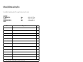
Technical publications ordering form
To order additional publications, please fill in a copy of this form and send it via mail to:
BULL CEDOC
357 AVENUE PATTON
B.P.20845
49008 ANGERS CEDEX 01
FRANCE
+33 (0) 2 41 73 72 66
+33 (0) 2 41 73 70 66
[email protected]
Designation
Reference
_ _
_ _
_ _ _ _
_
[ _ _ ]
_ _
_ _
_ _ _ _
_
[ _ _ ]
_ _
_ _
_ _ _ _
_
[ _ _ ]
_ _
_ _
_ _ _ _
_
[ _ _ ]
_ _
_ _
_ _ _ _
_
[ _ _ ]
_ _
_ _
_ _ _ _
_
[ _ _ ]
_ _
_ _
_ _ _ _
_
[ _ _ ]
_ _
_ _
_ _ _ _
_
[ _ _ ]
_ _
_ _
_ _ _ _
_
[ _ _ ]
_ _
_ _
_ _ _ _
_
[ _ _ ]
_ _
_ _
_ _ _ _
_
[ _ _ ]
_ _
_ _
_ _ _ _
_
[ _ _ ]
[ _ _ ]
Phone:
FAX:
E-Mail:
Qty
: The latest revision will be provided if no revision number is given.
NAME:
Date:
COMPANY:
ADDRESS:
PHONE:
E-MAIL:
For Bull Subsidiaries:
Identification:
For Bull Affiliated Customers:
Customer Code:
For Bull Internal Customers:
Budgetary Section:
For Others: Please ask your Bull representative.
FAX:
BLANK
BULL CEDOC
357 AVENUE PATTON
B.P.20845
49008 ANGERS CEDEX 01
FRANCE
REFERENCE
86 A1 25EG 03