1
MAXDATA PLATINUM 9000-4R Server System
OM12884
Product Guide
2
Contents
Part I: User’s Guide
11
Regulatory Specifications and Disclaimers ...........................................................................................13
Declaration of the Manufacturer or Importer ...................................................................................13
Safety Compliance ...........................................................................................................................13
Electromagnetic Compatibility (EMC) ..............................................................................................13
Electromagnetic Compatibility Notices (International) .....................................................................13
Europe (CE Declaration of Conformity) ............................................................................................13
1 System Description
15
Introduction ...........................................................................................................................................15
Chassis Description...............................................................................................................................16
External Chassis Features .................................................................................................................... 17
Chassis Front....................................................................................................................................17
Front Panel .......................................................................................................................................17
Peripheral Bay ..................................................................................................................................19
Hot-swap Hard Disk Drive Bay........................................................................................................ 20
Removable Media Drive Bays ..........................................................................................................21
SCSI Backplane Board .....................................................................................................................21
Processor/Memory Subsystem Serviceability Status Indicators .................................................... 22
Chassis Back ................................................................................................................................... 23
Back Panel........................................................................................................................................24
Power Supply LED Indicators.......................................................................................................... 25
Chassis Top ..................................................................................................................................... 26
I/O Subsystem Serviceability Indicators ......................................................................................... 26
Internal Chassis Features ..................................................................................................................... 27
Power Subsystem ........................................................................................................................... 27
Power Supply Modules ................................................................................................................... 27
Redundant AC Power Source Operation......................................................................................... 28
Plug-in DC-to-DC Converters.......................................................................................................... 28
Processor Power Pods .................................................................................................................... 28
The Power Distribution Board ......................................................................................................... 28
Cooling Subsystem ......................................................................................................................... 28
2 Board Set Description
31
System Board Set ............................................................................................................................... 32
Processor Board.............................................................................................................................. 33
Processor Overview........................................................................................................................ 34
Memory Boards .............................................................................................................................. 34
I/O Board......................................................................................................................................... 35
I/O Riser .......................................................................................................................................... 35
Midplane Board ............................................................................................................................... 36
Front Panel Board............................................................................................................................ 36
SCSI Backplane Board .................................................................................................................... 36
Peripherals............................................................................................................................................ 36
External SCSI Connector (Optional) ................................................................................................ 36
Add-In Board Slots .......................................................................................................................... 37
Video .................................................................................................................................................... 37
SCSI Controller ..................................................................................................................................... 37
ICH4 IDE Controller.............................................................................................................................. 37
Server Management ............................................................................................................................ 38
Baseboard Management Controller (BMC)..................................................................................... 38
QLogic GEM359 SCSI Hot-swap Controller ........................................................................................ 39
MAXDATA PLATINUM 90004R Server System
3
3 Configuration Software and Utilities
41
Power-on Sequence and Power-on Self-Test (POST) ...........................................................................41
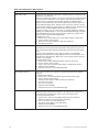
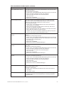
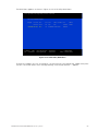
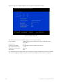
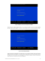
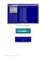
The Extensible Firmware Interface (EFI) Boot Manager .......................................................................41
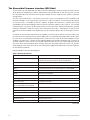
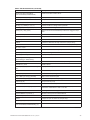
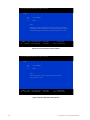
The Extensible Firmware Interface (EFI) Shell ..................................................................................... 44
Using BIOS Setup ................................................................................................................................ 46
Starting Setup ................................................................................................................................. 46
Record Your Setup Settings ............................................................................................................ 46
Navigating Setup Utility Screens......................................................................................................47
Primary Screens ...............................................................................................................................47
Advanced.............................................................................................................................................. 49
Security ................................................................................................................................................ 50
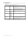
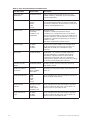
System Management ............................................................................................................................51
Exit ....................................................................................................................................................... 53
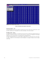
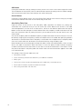
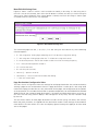
LSI SCSI Utility ..................................................................................................................................... 54
Clearing CMOS ............................................................................................................................... 60
BIOS Recovery Mode ...........................................................................................................................61
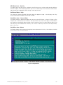
Using the SEL Viewer Utility ................................................................................................................ 62
Running the SELViewer Utility ........................................................................................................ 62
Splash Screen ................................................................................................................................. 63
Graphical User Interface.................................................................................................................. 63
Pull-Down Menu – File.................................................................................................................... 66
File Menu Item – Open ................................................................................................................... 66
File Menu Item – Save As ............................................................................................................... 67
File Menu Item – Exit ...................................................................................................................... 67
Pull-Down Menu – SEL ................................................................................................................... 67
SEL Menu Item – Reload ................................................................................................................ 68
SEL Menu Item – Properties........................................................................................................... 68
SEL Menu Item – Clear SEL............................................................................................................ 68
SEL Menu Item – Display In Hex / Display In Text .......................................................................... 68
SEL Menu Item – Sort By ............................................................................................................... 69
Pull-Down Menu – Help .................................................................................................................. 69
Help Menu Item – General Help...................................................................................................... 69
Help Menu Item – About................................................................................................................. 69
Command Line Interface..................................................................................................................70
System Maintenance Utility ..................................................................................................................70
Remote SMU Keyboard Support......................................................................................................71
Local SMU Keyboard Support..........................................................................................................71
About Box Information .................................................................................................................... 72
SMU Application Startup and Shutdown ............................................................................................. 73
Installation of SMU Software .......................................................................................................... 73
Discovery of Servers That Support the SMU.................................................................................. 73
Connections Between SMU Applications and Core Components...................................................74
Remote.............................................................................................................................................74
Local.................................................................................................................................................74
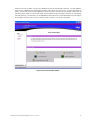
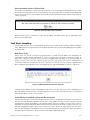
Startup of the Remote SMU Application .........................................................................................74
Startup of the Local SMU Application............................................................................................. 77
Running from CD............................................................................................................................. 77
Running from the System Partition ................................................................................................. 78
Shutdown of the SMU Application.................................................................................................. 78
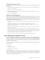
Server Management Configuration Task.............................................................................................. 78
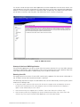
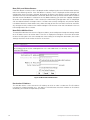
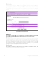
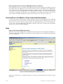
LAN Channel Configuration Subtask............................................................................................... 79
LAN Channel Configuration Initial View .......................................................................................... 79
Access Mode .................................................................................................................................. 80
Always Available.............................................................................................................................. 80
Disabled .......................................................................................................................................... 80
Privilege Level Limit ........................................................................................................................ 80
4
Contents
Callback ........................................................................................................................................... 80
User................................................................................................................................................. 80
Operator .......................................................................................................................................... 80
Administrator................................................................................................................................... 80
Enable DHCP................................................................................................................................... 80
Host IP Address .............................................................................................................................. 80
Subnet Mask ....................................................................................................................................81
Default Gateway IP Address ............................................................................................................81
Default Gateway MAC Address .......................................................................................................81
Automatically Resolve Default Gateway MAC Address...................................................................81
Backup Gateway IP Address ............................................................................................................81
Backup Gateway MAC Address .......................................................................................................81
Automatically Resolve Backup Gateway MAC Address ..................................................................81
Default LAN Configuration Settings Set by the SMU ..................................................................... 82
Gratuitous ARPs may be enabled ................................................................................................... 82
Authentication enables are enabled ................................................................................................ 82
User-level authentication is disabled ............................................................................................... 82
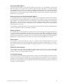
LAN Alert Configuration.................................................................................................................. 82
Enable LAN Alerting........................................................................................................................ 83
SNMP Community String................................................................................................................ 83
Alert Settings .................................................................................................................................. 83
New, Edit, and Delete Buttons........................................................................................................ 84
New/Edit LAN Alert View ............................................................................................................... 84
Destination IP Address.................................................................................................................... 84
Destination MAC Address............................................................................................................... 85
Automatically Resolve Destination MAC Address .......................................................................... 85
Number of Retries........................................................................................................................... 85
Retry Interval................................................................................................................................... 85
Enable Alert Acknowledge.............................................................................................................. 85
Use Default Gateway ..................................................................................................................... 85
Serial Over LAN Configuration View............................................................................................... 86
Enable Serial Over LAN................................................................................................................... 86
SOL Privilege Level ......................................................................................................................... 86
Number of Retries........................................................................................................................... 86
Retry Interval................................................................................................................................... 86
Baud Rate........................................................................................................................................ 86
Default SOL Settings ...................................................................................................................... 86
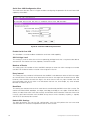
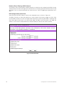
User Configuration Subtask ............................................................................................................ 87
User Configuration Initial View........................................................................................................ 87
Edit User View................................................................................................................................. 88
Enable User ..................................................................................................................................... 88
Enter Username .............................................................................................................................. 88
Clear Password ............................................................................................................................... 88
Enter/Verify New Password ............................................................................................................ 89
User Privilege Level for LAN Channels ........................................................................................... 89
User Privilege Level for Serial/Modem Channel ............................................................................. 89
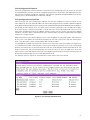
Platform Event Filtering (PEF) Subtask ........................................................................................... 90
PEF Configuration Initial View ......................................................................................................... 90
Enable PEF .......................................................................................................................................91
Enable SEL Event Messages for PEF Actions .................................................................................91
PEF Startup Delay ............................................................................................................................91
Alert Startup Delay...........................................................................................................................91
PEF Action Global Settings ..............................................................................................................91
Power Cycle .....................................................................................................................................91
Reset ................................................................................................................................................91
Power Down ....................................................................................................................................91
MAXDATA PLATINUM 90004R Server System
5
Diagnostic Interrupt..........................................................................................................................91
Alert..................................................................................................................................................91
Event Filter Settings View ............................................................................................................... 92
Edit Event Filter View ...................................................................................................................... 93
Enable Event Filter .......................................................................................................................... 93
Enable Alerts .................................................................................................................................. 93
Policy Number Associated With This Event Filter........................................................................... 93
Chassis Action Associated With This Event Filter........................................................................... 93
Configure Policies Button................................................................................................................ 93
OK Button ....................................................................................................................................... 94
Cancel Button.................................................................................................................................. 94
Alert Policy Table View.................................................................................................................... 94
Edit ................................................................................................................................................. 95
Edit Alert Policy Entry View ............................................................................................................ 96
Enable Policy Entry.......................................................................................................................... 96
Policy Number................................................................................................................................. 96
Policy Type ...................................................................................................................................... 97
Select the Destination..................................................................................................................... 97
OK Button ....................................................................................................................................... 97
Cancel Button.................................................................................................................................. 97
Serial/Modem Channel Configuration Subtask ............................................................................... 98
Serial/Modem Channel Configuration Initial View........................................................................... 98
General Settings.............................................................................................................................. 98
Connection Mode............................................................................................................................ 98
Direct Connect Mode...................................................................................................................... 98
Modem Mode ................................................................................................................................ 98
Access Mode ................................................................................................................................. 98
Pre-boot only................................................................................................................................... 99
Always Available.............................................................................................................................. 99
Shared ............................................................................................................................................. 99
Disabled .......................................................................................................................................... 99
Privilege Level Limit ........................................................................................................................ 99
IPMI Messaging Communication Settings ..................................................................................... 99
Flow Control .................................................................................................................................... 99
Baud Rate........................................................................................................................................ 99
Enable Data Terminal Ready (DTR) Hang-up .................................................................................. 99
Default Serial/Modem Configuration Settings Set By the SMU ..................................................... 99
Modem Mode Configuration View................................................................................................ 100
Modem Init String ......................................................................................................................... 100
Modem Escape Sequence ............................................................................................................ 100
Hang-up Sequence........................................................................................................................ 100
Dial Command................................................................................................................................101
Ring Duration .................................................................................................................................101
Ring Dead Time..............................................................................................................................101
Destination Dial Strings View.........................................................................................................101
New/Edit Dial String View..............................................................................................................102
Page Destination Configuration View.............................................................................................102
Enable Paging.................................................................................................................................103
Page Blackout Interval....................................................................................................................103
Call Retry Interval ...........................................................................................................................103
Edit Page Destination View........................................................................................................... 104
General Settings............................................................................................................................ 104
Dial String ...................................................................................................................................... 104
Flow Control .................................................................................................................................. 104
Baud Rate...................................................................................................................................... 104
Stop Bits........................................................................................................................................ 104
Data Bits ....................................................................................................................................... 104
6
Contents
Parity ............................................................................................................................................. 104
Call Retries .....................................................................................................................................105
Terminal Mode Configuration View................................................................................................105
Terminal Mode Settings .................................................................................................................105
Enable/Disable Terminal Mode ......................................................................................................105
Enable/Disable Line Editing ...........................................................................................................105
Delete Control ................................................................................................................................105
Turn BMC Echo of Received Characters On ..................................................................................105
Enable Handshake When BMC Ready To Receive Another Message.......................................... 106
Newline Output Sequence............................................................................................................ 106
Newline Input Sequence............................................................................................................... 106
Power Configuration Subtask........................................................................................................ 106
Power Configuration View ............................................................................................................ 106
Save Operation Success/Failure View ...........................................................................................107
Task Error Handling .............................................................................................................................107
Data Entry Errors............................................................................................................................107
Internal Errors For Which a View Can Be Generated .....................................................................107
Data Corruption Errors That the SMU Application Can Handle..................................................... 108
Internal Errors For Which a View Cannot Be Generated .................................................................... 108
Help .................................................................................................................................................... 108
Help for the Remote SMU Application.......................................................................................... 108
Remote SMU Help Use Cases...................................................................................................... 109
ISM Front-end Help....................................................................................................................... 109
SMU Table of Contents Help ........................................................................................................ 109
Help Buttons ................................................................................................................................. 109
Help for the Local SMU Application .................................................................................................... 110
Shutting Down the Server................................................................................................................... 111
EFI Platform Diagnostic Tests ............................................................................................................. 111
Starting the Application.................................................................................................................. 111
Understanding the General User Interface .................................................................................... 112
Understanding Basic Testing.......................................................................................................... 112
Enabling Tests For Execution ......................................................................................................... 112
Setting Test Options ...................................................................................................................... 113
Interpreting Results ........................................................................................................................ 113
Getting Help On Individual Tests.................................................................................................... 113
Viewing System Information .......................................................................................................... 113
Viewing the Test Log ..................................................................................................................... 113
EFI Service Partition ............................................................................................................................ 114
Service Partition Requirements ..................................................................................................... 114
Installing Service Partition Files ..................................................................................................... 114
Installation Requirements............................................................................................................... 114
Installing the Files........................................................................................................................... 114
Booting the Server from the Service Partition ............................................................................... 115
Locally ............................................................................................................................................ 115
Console Redirection ............................................................................................................................ 115
Operation ....................................................................................................................................... 115
Keystroke Mappings....................................................................................................................... 116
Limitations...................................................................................................................................... 118
Interface to Server Management ................................................................................................... 118
Sample Setup for Console Redirection .......................................................................................... 119
Server Configuration ...................................................................................................................... 119
Console Configuration.................................................................................................................... 119
Terminal Mode Overview....................................................................................................................120
Setup and Configuration.................................................................................................................120
Connection Mechanism .................................................................................................................120
Hardware Setup .............................................................................................................................120
Configuration Using System Maintenance Utility (SMU) ...............................................................120
MAXDATA PLATINUM 90004R Server System
7
Serial Channel Configuration ..........................................................................................................120
Direct Connection Mode ................................................................................................................120
Modem Connection Mode.............................................................................................................121
Sample Setup for Terminal Mode ..................................................................................................121
Server Configuration: .....................................................................................................................121
Console Configuration:...................................................................................................................122
Logging Into the Terminal Mode Session ......................................................................................122
User Configuration .........................................................................................................................122
Username and Password Restrictions ...........................................................................................122
Terminal Mode Configuration.........................................................................................................122
Line Editing.....................................................................................................................................123
Echo ...............................................................................................................................................123
Handshaking...................................................................................................................................123
Delete Control Sequence ...............................................................................................................123
Input Newline Sequence................................................................................................................123
Output Newline Sequence.............................................................................................................123
Security Information.......................................................................................................................123
Terminal Mode Commands............................................................................................................124
Input Restrictions ...........................................................................................................................124
Syntax ............................................................................................................................................124
Command Length ..........................................................................................................................124
Character Support ..........................................................................................................................124
Special Character Handling - <ESC> character ..............................................................................124
Special Character Handling - <DEL> or <BKSP> character...........................................................124
Special Character Handling - Line Continuation character..............................................................124
Special Character Handling - Illegal characters...............................................................................124
Hex-ASCII Command Format.........................................................................................................124
Text Command Format ..................................................................................................................125
Examples........................................................................................................................................125
Terminal Mode IPMI Message Bridging ........................................................................................125
4 Hot-swapping System Components
135
Tools and Supplies Needed .................................................................................................................135
Equipment Log ...............................................................................................................................135
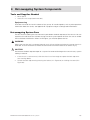
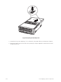
Hot-swapping System Fans ................................................................................................................135
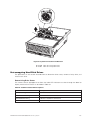
Hot-swapping Hard Disk Drives ..........................................................................................................137
Determining Drive Status ...............................................................................................................137
Removing a Hard Disk Drive ..........................................................................................................138
Installing a Hard Disk Drive ...........................................................................................................138
Hot-swapping Power Supplies ............................................................................................................138
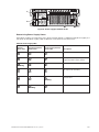
Determining Power Supply Status .................................................................................................139
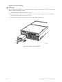
Removing a Power Supply .............................................................................................................140
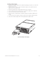
Installing a Power Supply ...............................................................................................................141
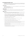
Hot Plugging PCI Add-in Cards ...........................................................................................................142
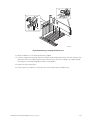
Removing Hot-plug PCI Add-in Cards ............................................................................................142
Installing Hot-plug PCI Add-in Cards ............................................................................................. 144
5 Warnings
147
WARNING: English (USA) .................................................................................................................. 148
AVERTISSEMENTS : Français.............................................................................................................150
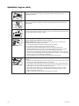
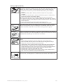
WARNUNG: Deutsch ..........................................................................................................................152
AVVERTENZA: Italiano....................................................................................................................... 154
ADVERTENCIA: Español .....................................................................................................................156
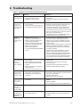
6 Troubleshooting
8
159
Contents
Figures
1.
2.
3.
4.
5.
6.
7.
8.
9.
10.
11.
12.
13.
14.
15.
16.
17.
18.
19.
20.
21.
22.
23.
24.
25.
26.
27.
28.
29.
30.
31.
32.
33.
34.
35.
36.
37.
38.
39.
40.
41.
42.
43.
44.
45.
46.
47.
48.
49.
50.
51.
52.
53.
54.
55.
MAXDATA PLATINUM 9000-4R Server Front View .....................................................................15
Chassis Front View.........................................................................................................................17
Front Panel Controls and Indicators ...............................................................................................18
Peripheral Bay ................................................................................................................................19
Hard Disk Drive Carrier.................................................................................................................. 20
DVD/CD-ROM and LS-240 Drive Carriers .....................................................................................21
Location of Processor/Memory Subsystem Serviceability Indicators .......................................... 22
Chassis Back Features .................................................................................................................. 23
Back Panel View Showing Indicator and Switch Locations............................................................24
Power Supply Indicators ............................................................................................................... 25
I/O Subsystem Serviceability Indicators ....................................................................................... 26
Fan Status Indicators..................................................................................................................... 29
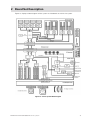
Server System Block Diagram .......................................................................................................31
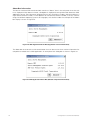
LSI SCSI Utility Main Menu .......................................................................................................... 55
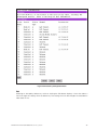
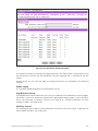
Adapter Properties ........................................................................................................................ 56
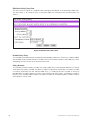
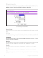
Device Properties.......................................................................................................................... 57
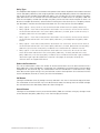
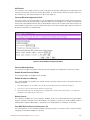
Device Properties Format Option ................................................................................................. 58
Device Properties Verify Option.................................................................................................... 58
Adapter and/or Device Properties Exit Menu ............................................................................... 59
SCSI Utility Exit Menu................................................................................................................... 59
SEL Viewer Utility Main Window .................................................................................................. 65
Status Box ..................................................................................................................................... 65
Message for Empty Event Log ..................................................................................................... 65
SEL Records Displayed in Hex Format ......................................................................................... 66
File Open Window ........................................................................................................................ 67
SEL Properties .............................................................................................................................. 68
Confirmation for Clearing SEL....................................................................................................... 68
Help Window ................................................................................................................................ 69
SMU Application About Box (Application version information)..................................................... 72
SMU Application About Box (Related component information).................................................... 72
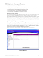
ISM Console.................................................................................................................................. 73
Service Partition Connection View.................................................................................................74
Service Partition Utilities ............................................................................................................... 75
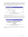
Socket Connection Error Message ................................................................................................76
SMU Version Compatibility Error ...................................................................................................76
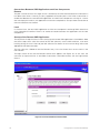
SMU Home View .......................................................................................................................... 77
LAN Channel Configuration .......................................................................................................... 79
LAN Alerting Configuration ........................................................................................................... 83
New/Edit LAN Alert View ............................................................................................................. 84
Serial Over LAN Configuration View............................................................................................. 86
User Configuration Main View ...................................................................................................... 87
Edit User Configuration View ........................................................................................................ 88
PEF Initial View ............................................................................................................................. 90
PEF Event Filter Settings View...................................................................................................... 92
Edit Event Filter Settings View...................................................................................................... 93
Alert Policy Configuration View..................................................................................................... 95
Edit Alert Policy Entry View .......................................................................................................... 96
Serial/Modem Channel Configuration Initial View ........................................................................ 98
Modem Settings ......................................................................................................................... 100
Modem Destination Dial Strings and Settings .............................................................................101
New/Edit Dial String View............................................................................................................102
Page Destination Configuration View ..........................................................................................103
Edit Page Destination Menu ....................................................................................................... 104
Terminal Mode Configuration Menu ............................................................................................105
Power Configuration Settings View ............................................................................................ 106
MAXDATA PLATINUM 90004R Server System
9
56.
57.
58.
59.
60.
61.
62.
63.
64.
65.
66.
67.
Save Operation Successful View .................................................................................................107
SMU Invalid Data Entry Error Example ........................................................................................107
Remote SMU Help Window (Browser-based) ............................................................................ 108
SMU Local Help Window............................................................................................................. 110
Opening the Back Top Cover .......................................................................................................136
System Fan Location and Removal ..............................................................................................137
Removing a Hard Disk Drive ........................................................................................................138
Power Supply Installation Order...................................................................................................139
Removing a Power Supply ...........................................................................................................140
Installing a Power Supply .............................................................................................................141
Removing a Hot-plug PCI Add-in Card ........................................................................................ 143
Installing a Hot-plug PCI Add-in Card ...........................................................................................145
Tables
1.
2.
3.
4.
5.
6.
7.
8.
9.
10.
11.
12.
13.
14.
15.
16.
17.
18.
19.
20.
21.
22.
23.
24.
25.
26.
27.
28.
29.
30.
31.
10
Server Physical Specifications .......................................................................................................15
Chassis Feature Summary .............................................................................................................16
Front Panel Control and Indicator Description................................................................................18
SCSI Hard Drive LED Details ........................................................................................................ 20
Processor/Memory Subsystem Serviceability Indicator Details ................................................... 22
Power Supply LED Status Indicators ........................................................................................... 25
Boot Maintenance Menu Options ................................................................................................. 42
EFI Shell Commands..................................................................................................................... 44
Using Setup Screens......................................................................................................................47
BIOS Setup Main Screen Menu Items.......................................................................................... 48
Processor Settings Submenu Items ............................................................................................. 48
BIOS Setup Advanced Screen Menu Items.................................................................................. 49
BIOS Setup Security Screen Menu Items..................................................................................... 50
BIOS Setup System Management Screen Menu Items ................................................................51
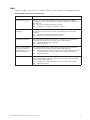
Setup Console Redirection Sub Menu Items................................................................................ 52
BIOS Setup Exit Screen Menu Items............................................................................................ 53
Abbreviations Used in Hex Mode Display..................................................................................... 64
Command Line Switches ...............................................................................................................70
Keyboard Support for Remote SMU Client ....................................................................................71
Common Buttons in SM Configuration Views .............................................................................. 79
Non-ASCII Key Mappings ............................................................................................................ 117
ASCII Key Mappings .................................................................................................................... 118
Terminal Mode Request to BMC .................................................................................................125
Terminal Mode Request from BMC .............................................................................................125
Supported BMC Combinations for IPMI Message Bridging ........................................................126
Terminal Mode Text Commands ..................................................................................................126
Boot Option Parameters ..............................................................................................................129
Terminal Mode Configuration.......................................................................................................133
SCSI Drive Status LED Descriptions ............................................................................................137
Power Supply LEDs .....................................................................................................................139
Symptom/Cause/Solution Troubleshooting Guide .......................................................................159
Contents
Part I: User’s Guide
1
System Description
2
Board Set Description
3
Configuration Software and Utilities
4
Hot-swapping System Components
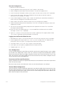
This manual consists of two parts:
!
•
User’s Guide describes procedures that DO NOT REQUIRE internal server access. You do not
need to be a qualified service technician to perform procedures listed in the User’s Guide.
•
Service Technician’s Guide describes procedures that REQUIRE internal server access. You
must be a qualified service configuration technician to perform procedures listed in the Service
Technician’s Guide.
WARNING
Only a QUALIFIED SERVICE TECHNICIAN is authorized to remove the server’s covers and to access
any of the components inside the server, except as noted herein. Before removing top covers or a
modules, see “Error! Reference source not found.” and “Warnings and Cautions”.
!
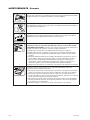
WARNING
Anchor the equipment rack: The equipment rack must be anchored to an unmovable support to prevent
it from falling over when one or more servers are extended in front of the rack on slides. The anchors
must be able to withstand a force of up to 113 kg (250 lbs.). You must also consider the weight of
any other device installed in the rack. A crush hazard exists should the rack tilt forward which could
cause serious injury.
Main AC power disconnects: You are responsible for installing an AC power disconnect for the entire
rack unit. This main disconnect must be readily accessible, and it must be labeled as controlling power
to the entire unit, not just to the server(s).
Grounding the rack installation: To avoid the potential for an electrical shock hazard, you must include
a third wire safety-grounding conductor with the rack installation. If the server power cord is plugged
into an AC outlet that is part of the rack, then you must provide proper grounding for the rack itself. If
the server power cord is plugged into a wall AC outlet, the safety-grounding conductor in the power
cord provides proper grounding only for the server. You must provide additional, proper grounding for
the rack and other devices installed in it.
Overcurrent protection: The server is designed for an AC line voltage source with up to 20 amperes of
overcurrent protection. If the power system for the equipment rack is installed on a branch circuit with
more than 20 amperes of protection, you must provide supplemental protection for the server.
MAXDATA PLATINUM 90004R Server System
11
!
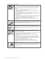
WARNING – POWER CORD RATING
Do not attempt to modify or use an AC power cord that is not the exact type required. You must use
a power cord that meets the following criteria:
!
•
Rating: For U.S./Canada cords must be UL Listed/CSA Certified, 16/3, 75C type, VW-1, SJT/SVT,
with NEMA 5-15P or NEMA 6-15P attachment plug and IEC 320 C13 input power connector
rated 15 amps. For outside U.S./Canada cords must be flexible harmonized (<HAR>) rated 250
V, 1.0 mm minimum conductor size with IEC 320 C13 input power connector and rated for no
less than 10 amps.
•
AC Attachment Connector, wall outlet end for outside U.S./Canada: The AC wall attachment
plug should be a three conductor grounding type, rated at 125 V, 15 amps and must be for
the configuration of the specific region or country. The AC wall attachment plug must bear at
least an accepted safety agency certification mark for the specific region or country.
•
Input Power Connector, server end: The connectors that plug into the AC receptacles on the
server must be an IEC 320, sheet C13, type female connector and are rated for 125 V/250 V,
15 A.
•
Cord length and flexibility: Cords must be less than 4.5 meters (14.76 feet) long.
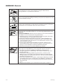
CAUTION
Temperature: The range of temperatures in which the server operates when installed in an equipment
rack, must not go below 10 °C (50 °F) or rise above 35 °C (95 °F). Extreme fluctuations in temperature
can cause a variety of problems in your server.
Ventilation: The equipment rack must provide sufficient airflow to the front of the server to maintain
proper cooling. The rack must also include ventilation sufficient to exhaust a maximum of 1500 W
(5,100 BTU/hr) for the server. The rack selected and the ventilation provided must be suitable to the
environment in which the server will be used.
12
Part I: User’s Guide
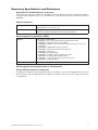
Regulatory Specifications and Disclaimers
Declaration of the Manufacturer or Importer
We hereby certify that this product is in compliance with European Union EMC Directive 89/336/EEC,
using standards EN55022 (Class A) and EN55024 and Low Voltage Directive 73/23/EEC, Standard
EN60950.
Safety Compliance
Europe:
Low Voltage Directive, 73/23/EECTUV/GS to EN60950 2nd Edition with
Amendments, A1 = A2 + A3 + A4
International:
TUV/CB to IEC 60950 3rd Edition, EN60 950 2nd Edition + Amd 1-4,
EMKO-TSE (74-SEC) 207/94 plus international deviations
Electromagnetic Compatibility (EMC)
Europe:
EMC Directive, 89/336/EEC:
• EN55022, Class A Limit, Radiated & Conducted Emissions
• EN55024, ITE Specific Immunity Standard
• EN61000-4-2, ESD Immunity (Level 2 Contact Discharge, Level 3 Air
Discharge)
• EN61000-4-3, Radiated Immunity (Level 2)
• EN61000-4-4, Electrical Fast Transient (Level 2)
• EN61000-4-5, AC Surge
• EN61000-4-6, Conducted RF
• EN61000-4-8, Power Frequency Magnetic Fields
• EN61000-4-11, Voltage Dips and Interrupts
• EN61000-3-2, Limit for Harmonic Current Emissions
• EN61000-3-3, Voltage Flicker
International:
CISPR 22, Class A Limit
Electromagnetic Compatibility Notices (International)
Europe (CE Declaration of Conformity)
This product has been tested in accordance too, and complies with the Low Voltage Directive (73/23/
EEC) and EMC Directive (89/336/EEC). The product has been marked with the CE Mark to illustrate
its compliance.
MAXDATA PLATINUM 90004R Server System
13
14
1 System Description
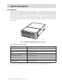
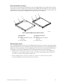
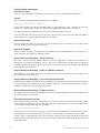
Introduction
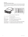
The MAXDATA PLATINUM 9000-4R as shown in Figure 1 is a compact, high-density rack-mount
server system with support for one to four Intel® Itanium® 2 processors and 32-GB DDR SDRAM
memory. The system is based on the Intel S870BN4 board set and the Intel® E8870 chipset. The
system supports hot-plug PCI and PCI-X add-in cards; hot-swap, redundant power supply modules;
hot-swap, redundant cooling fans; and hot-swap hard disk drives. The system also provides interlock
status LEDs for critical system interconnects. The system supports Symmetric Multiprocessing (SMP)
and a variety of operating systems. Table 1 presents an overview of the server system’s physical
characteristics.
OM12884
Figure 1. MAXDATA PLATINUM 9000-4R Server Front View
Table 1. Server Physical Specifications
1.
Characteristic
Specification
Height
178 mm (6.9 inches, 4U)
Width
445 mm (17.5 inches)
Depth
711 mm (28.0 inches)
Weight (max.)
48 kg (106 lbs)1
Required front clearance
76 mm cm (3 inches)
Required rear clearance
152 mm (6 inches)
Required side clearance
25 mm (1 inch)
Heat Dissipation
1500 W (5,100 BTU/hr)
The system weight listed above is an estimate for a fully configured system and will vary depending on the number of
peripheral devices and add-in cards as well as the number of processors and DIMMs installed in the system.
MAXDATA PLATINUM 90004R Server System
15
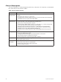
Chassis Description
The chassis provides a modularized processor/memory subsystem, I/O subsystem, and peripheral
bay. Other features are outlined in Table 2.
Table 2. Chassis Feature Summary
Feature
Comment
Server
Configuration
• Stand-alone system including external I/O PCI slots and disk expansion as needs
grow
• Supports Intel® Itanium® 2 processors
• 32-GB Double Data Rate (DDR) Synchronous Dynamic Random Access Memory
(SDRAM) memory support with 2-GB DIMMs
Expansion
and Servicing
•
•
•
•
•
•
•
•
16
Front access to hot-swap hard disk drives
Three hot-swap 1-inch Ultra320 SCSI hard disk drives
Rear access to hot-swap power supplies
Two hot-swap 1200-W power supplies in a redundant (1+1, 220 V) configuration
with redundant power cords (one per power supply)
Four top access hot-swap system fans in a redundant (3+1) configuration
Dockable processor/memory subsystem, I/O subsystem and peripheral bay
Dockable slim-line LS-240 and DVD/CD-ROM drives
Interlock status indicator LEDs for major modulesEight 64-bit hot-plug PCI-X
slots
Management
•
•
•
•
•
Remote management through LAN or modem
Emergency Management Port
Intelligent Platform Management Interface (IPMI) 1.5 compliant
Wired for Management (WfM) 2.0 compliant
Remote diagnostics support through LAN or modem
Upgrades
• Field upgradeable to the next generation Itanium® processor family
• Multi-generational chassis
System-level
scalability
•
•
•
•
Up to 32-GB DDR SDRAM
One to four Intel® Itanium® 2 processors
External I/O (8 PCI slots) and disk expansion
External SCSI connector
System Description
External Chassis Features
System controls and indicators are located in several places on the chassis as follows:
•
Chassis front:
– Front panel: Front panel switches and LEDs
– Peripheral bay: Hard disk drive LEDs
– Processor/memory module: Subsystem serviceability LEDs
•
Chassis back:
– Power supply modules (See Power Subsystem for details)
– Hot-plug Indicator Board (HPIB)
•
Chassis top:
– I/O subsystem
– Fan bay (See Cooling Subsystem for details)
Each of these areas is discussed in this section.
Chassis Front
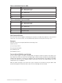
Figure 2 shows the front view of the chassis with the snap-on bezel in place. The bezel provides
access to the front panel board and the peripheral bay.
B
A
C
OM12885
Figure 2. Chassis Front View
A.
B.
C.
Bezel
Front Panel
Peripheral Bay
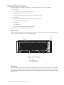
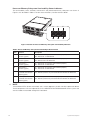
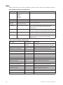
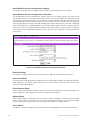
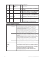
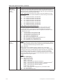
Front Panel
The front panel is located to the right of the processor/memory subsystem and provides user interface
for system management via switches and status indicatosr LEDs. The front panel also contains the
speaker. Figure 3 shows the control buttons and status indicators on the front panel. Table 3 describes
their features.
MAXDATA PLATINUM 90004R Server System
17
A
E
B
C
D
F
G
H
I
OM12886
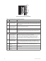
Figure 3. Front Panel Controls and Indicators
Table 3. Front Panel Control and Indicator Description
Item
Feature
Description
Switches
A.
System ID Switch
Toggle switch for blue System ID LEDs (the front panel system ID LED
is located inside the system ID switch). See E below for description of
LED operation.
B.
Assert SDINT
(System Diagnostic
Interrupt) Switch
Asserts SDINT. This switch is accessible through a small opening and
requires a narrow tool to activate.
C.
Reset switch
Resets the system.
D.
Power switch
Toggles system power. A delay of ~5 seconds is required between
pressing the power switch to power down and then power up the
system.
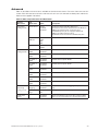
LED Indicators
18
E.
System ID (Blinking
or Solid Blue). The
system ID LEDs are
located inside the
system ID switch on
the front panel and
on the back panel
Identifies the system. The system ID is activated either by the system
ID switch or through server management software.
Pressing the system ID switch once turns on the LEDs solid blue.
Press the system ID switch again, the solid blue LEDs turn off.
Remove activation - LEDs turn on blinking for 4 minutes (max). The
system ID LEDs cannot be turned off by pressing the switch.
F.
Main Power (Solid
or Blinking Green)
A continuously lit LED indicates the presence of DC power in the
system. The LED goes out when the power is turned off or the power
source is disrupted. Blinking Green indicates the system is in sleep
mode.
G.
Power Fault (Solid
Amber)
Indicates any system power faults. Off indicates power is OK.
H.
Cooling Fault (Solid
Amber)
Indicates any system cooling faults. Off indicates system
cooling is OK.
I.
General Fault (Solid
amber)
Indicates a system failure. Off indicates system is OK.
System Description
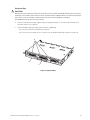
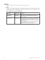
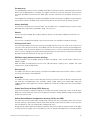
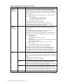
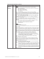
Peripheral Bay
!
CAUTION
Removal of the LS240 and the DVD/CD drives requires removal of the peripheral bay from the chassis.
Therefore, the LS240 and the DVD/CD drives cannot be hot-swapped. Power must be removed from
the system when installing or removing these drives to avoid component damage.
The peripheral bay consists of two sections:
•
The hot-swap hard drive bay (upper section) supporting three 1-inch hot-swap Ultra320 SCSI
hard disk drives (A in Figure 4).
•
The removable media drive bay (lower section) supporting:
– One 1⁄2-inch IDE DVD/CD-ROM (B in Figure 4)
– One 1⁄2-inch IDE LS-240 drive (C in Figure 4) or removable EMI Filler Panel (D in Figure 4).
A
B
C
OM12905
Figure 4. Peripheral Bay
MAXDATA PLATINUM 90004R Server System
19
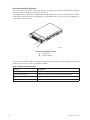
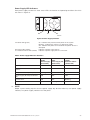
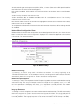
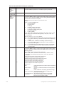
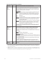
Hot-swap Hard Disk Drive Bay
The hot-swap hard disk drive carrier (see Figure 5) is designed to accept 15,000-RPM (and slower)
Ultra320 SCSI technology SCA-type hard disk drives.
The peripheral bay is designed to support Low Voltage Differential (LVD) SCSI disk drives only. SingleEnded (SE) SCSI devices are not supported in the peripheral bay. SE drives are only supported on
the external SCSI connector.
A
B
OM12933
Figure 5. Hard Disk Drive Carrier
A.
B.
Carrier latch
Status indicator
The carriers contain light-pipes that allow dual color LED indicators to show thsrough the bezel to
display hard disk drive status as described in Table 4.
Table 4. SCSI Hard Drive LED Details
20
Feature
Description
Green, flashing
Indicates the hard drive is active
Yellow/Green flashing
Indicates a hard drive fault and hard drive is powered
Yellow/Blank flashing
Indicates a hard drive fault and hard drive is not powered
Not illuminated
Indicates no hard drive is installed in the bay
System Description
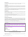
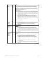
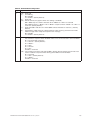
Removable Media Drive Bays
The slim-line LS-240 and DVD/CD-ROM drives and their adapter boards are installed in plastic carriers
(see Figure 6) and are inserted from the front of the removable media drive bay. You must switch off
system power and remove the peripheral bay to remove or install these drives. If the LS-240 is not
included with the server, then a filler panel must be used (see D in Figure 6).
C
B
A
C
B
A
OM12934
Figure 6. DVD/CD-ROM and LS-240 Drive Carriers
DVD/CD-ROM
A. Latch
B. Adapter board with locking
connector
C. Plastic Carrier
LS-240 Floppy Disk Drive
A. Latch
B. Adapter board with locking
connector
C. Plastic Carrier
SCSI Backplane Board
The SCSI backplane board mates with the midplane board connector. It contains three 80-pin Single
Connector Attachment (SCA)-2 connectors for hot-swap hard disk drives. The SCSI backplane board
performs the tasks associated with hot-swapping the hard disk drives and enclosure monitoring and
management. The features supported by the SCSI backplane board include the following:
•
Monitoring the SCSI bus for enclosure services messages, and acting on them appropriately.
Examples of such messages include: activate a drive fault indicator; power down a drive that
has failed; and report SCSI backplane temperature.
•
SAF-TE intelligent agent, which acts as proxy for “dumb” I2C devices (that have no bus
mastering capability) during intrachassis communications.
MAXDATA PLATINUM 90004R Server System
21
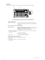
Processor/Memory Subsystem Serviceability Status Indicators
The serviceability status indicators contained in the processor/memory subsystem are shown in
Figure 7 and described in Table 5. To view these indicators, remove the front bezel.
A
C
E
B
D
F
OM12896
Figure 7. Location of Processor/Memory Subsystem Serviceability Indicators
Table 5. Processor/Memory Subsystem Serviceability Indicator Details
Item
Feature
Description
A
Processor 1
Present (green)
On – Processor 1 is present and installed properly
Off – Processor 1 not detected
B
Processor 2
Present (green)
On – Processor 2 is present and installed properly
Off – Processsor 2 not detected
C
Processor 3
Present (green)
On – Processor 3 is present and installed properly
Off – Processor 3 not detected
D
Processor 4
Present (green)
On – Processor 4 is present and installed properly
Off – Processor 4 not detected
E
Memory Board 1
Interlock to Processor
Board (green)
On – Memory board 1 is inserted properly into the processor board
Off – Memory board 1 to processor board interlock not detected
F
Memory Board 2
Interlock to Processor
Board (green)
On – Memory board 2 is inserted properly into the processor board
Off – Memory board 2 to processor board interlock not detected
NOTE
Two additional LEDs (Green and Amber) and a switch appear on the left side of the processor board.
These components are not implemented in the MAXDATA PLATINUM 9000-4R Server system and
are not visible or accessible through the front bezel.
22
System Description
Chassis Back
Figure 8 shows the features found on the chassis back panel including the I/O bay, the power supply
modules, and user-accessible connectors.
A
B
C
D
G
F
E
J
I
H
OM12888
Figure 8. Chassis Back Features
A . AC input power connectors
B . PCI Slots (All slots support hot-plug PCI add-in cards)1
Slots 1 through 4
100-MHz, 64-bit PCI-X slot, half length
Slot 5
100-MHz, 64-bit PCI-X slot, full length
Slots 6 through 8
133-MHz, 64-bit PCI-X slot, full length
C . Video port, standard VGA compatible, 15-pin connector
D . External SCSI connector (optional)2
E . Serial port, 9-pin RS-232 connector3
F . Ethernet port, RJ45 connector
G . Four USB ports, 4-pin connectors
H . ICMB connectors in/out (optional
ICMB port 1, SEMCONN 6-pin connector
ICMB port 2, SEMCONN 6-pin connector
I . Power supply 2
J . Power supply 1
Notes: 1. PCI slots support 3.3 V signal adapter cards only.
2. External SCSI bus supports both LVDS and SE signals via the external SCSI connector.
3. Emergency Management Port (EMP) access is provided via shared serial port.
MAXDATA PLATINUM 90004R Server System
23
Back Panel
Figure 9 shows the location of the indicators and controls found on the back panel.
A
B
C
D
OM12889
Figure 9. Back Panel View Showing Indicator and Switch Locations
System ID Indicator LED
A. System ID LED (blue)
Identifies the system. The system ID LED is activated either
by the System ID switch on the front panel or through server
management.
Hot-plug PCI Add-in Card Switches and LEDs
B. Attention Switch
Notifies PCI hot-plug system software (ACPI PHP ASL) that a PCI
hot-plug operation is about to take place.
WARNING: Verify in BIOS release notes that this feature is
supported before using the Attention button.
MRL (Manually-operated Disables power to the PCI slot if a PCI add-in card is present.
Retention Latch) Switch
Green LED
On – PCI slot is powered.
Off – PCI slot is powered down.
Amber LED
On – PCI slot or card fault condition.
Ethernet Interface Status LED Indicators
24
C. Network Interface Status
LED (green)
Shows activity and status.
D. Network Interface Status
LED (yellow)
Shows activity and status.
System Description
Power Supply LED Indicators
Each power supply module has three status LEDs the location and operating conditions for which
are shown in Figure 10.
A
B
C
OM12887
Figure 10. Power Supply Indicators
A. Power LED (green)
B. Failure LED (amber)
C. Predictive Failure LED (amber)
On - indicates the presence of DC power in the system
Blinking - indicates the system is in ACPI sleep mode
Off - indicates the power is turned off or the power source is
disrupted
Indicates a power supply failure
Indicates a power supply failure is imminent
Table 6. Power Supply LED Status Indicators
A
(PWR)
Power Supply
(Green LED)
B
(FAIL)
Power Supply Fail
(Amber LED)
C
(PFAIL)
Predictive Failure
(Amber LED)
No AC power to all PSU
OFF
OFF
OFF
No AC power to this PSU only or PS
failure
OFF
OFF
ON
AC present / Standby Output On
Blinking
OFF
OFF
Power supply DC outputs ON and
OK
ON
OFF
OFF
Current limit
ON
OFF
Blinking
Predictive failure
ON
Blinking/Latched
OFF
NOTE
Proper system cooling requires that the power supply bay be filled either by two power supply
modules, or a power supply module and a filler panel.
MAXDATA PLATINUM 90004R Server System
25
Chassis Top
I/O Subsystem Serviceability Indicators
Figure 11 shows the I/O subsystem serviceability indicators. The indicators are located on the I/O board
and are visible through the system top cover via light pipes. The I/O serviceability indicators provide
system power, system reset, and interlock status for various subsystem and module connectors.
These LEDs are powered by standby voltage to provide status as long as AC power is supplied to
the system.
Attention
System In Reset
OK
System Power Good
OK
IO Bd/Midplane Interlock
OK
IO Riser/IO Bd Interlock
OK
Proc/Mem/CPU Bd Interlock
OK
SCSI Bd/Midplane Interlock
OM12939
Figure 11. I/O Subsystem Serviceability Indicators
System In Reset (amber) On – system reset asserted
Off – system reset not asserted
System Power Good
(green)
On – system power within normal operational range
Off – system power failure
I/O Board to Midplane
Board Interlock (green)
On – I/O subsystem inserted properly into midplane board
Off – I/O subsystem to midplane board interlock not detected
I/O Riser to I/O Board
Interlock (green)
On – I/O riser inserted properly into I/O board
Off – I/O riser to I/O board interlock not detected
Processor/Memory/CPU
Board Interlock (green)
On – processor/memory subsystem inserted properly into midplane board
Off – processor/memory subsystem to midplane board interlock not detected
SCSI Board to Midplane On – SCSI backplane board inserted properly into midplane board
Board Interlock (green) Off – SCSI backplane board to midplane board interlock not detected
26
System Description
Internal Chassis Features
Power Subsystem
!
WARNING
Only qualified technical personnel should access the processor, memory, and non-hot-plug I/O
subsystem areas while the system is energized as some exposed circuits exceed 240 VA and may
cause burn injury if accidentally contacted.
The power subsystem can be configured as following:
•
Two power supply modules installed, (1+1) redundancy at 220 VAC
•
One power supply module installed, non-redundant at 220 VAC only
•
Two power supply modules installed, non-redundant for 120 VAC
The power subsystem consists of the following:
•
Power supply modules
•
Plug-in DC-to-DC converters
•
Power pods (located adjacent to the processors on processor board)
•
The power distribution board
Power Supply Modules
The power supply modules are Server System Infrastructure (SSI) compliant, universal AC input with
Power Factor Correction (PFC) Distributed Power Supplies (DPS). The power supply modules are rated
at 1200 W over an input range of 180-264 VAC, and at 700 W over an input range of 90-132 VAC.
One power supply module connected to 220 VAC is capable of handling the worst-case power
requirements for a fully configured system: four processors, 32 GB of memory, eight PCI add-in
cards, three hard disk drives, a DVD or CD drive, and an LS-240 drive.
The power supply has two DC outputs: 48 V (main) and 12 V (standby). The 48 V main power is
distributed throughout the server and is converted locally at point-of-load using either embedded or
plug-in DC-to-DC converters.
In an N+1 configuration the 48 VDC outputs have active (forced) current sharing and 12 VDCSB outputs
have passive current sharing.
The two externally enabled outputs have the following ratings:
•
+48 VDC at: 24.0 A @HI line /13.5 A @LO line
•
+12 VDCSB at: 4 A @any line
MAXDATA PLATINUM 90004R Server System
27
Redundant AC Power Source Operation
Each power supply module requires one power cord to supply AC power to the system. When two
power supply modules and two power cords are installed, the system supports (1+1) power cord
redundancy at 220 VAC. This feature allows the system to be powered by two separate AC sources.
In this configuration, the system continues to operate without interruption if one of the AC sources
fails.
Plug-in DC-to-DC Converters
Two types of plug-in DC-to-DC converters are used in the system:
•
5 V output
•
Voltage ID (VID) (2.5 or 3.3 V output)
A control bit set by the board determines output voltage on the VID DC-to-DC converters. The T-DCto-DC converters contain an LED for failure indication.
The processor board supports three VID T-DC-to-DC converters (one 3.3 V and two 2.5 V).
The I/O board supports two 5 V and two VID (3.3 V) T-DC-to-DC converters. Each T-DC-to-DC converter
powers a separate plane on the board; therefore all DC-to-DC converter slots must be populated.
Processor Power Pods
Dedicated power pods supply power to each processor. The input connector of the power pod is
connected to the 48 V power on the processor board via a short cable. The output connector of the
power pod mates directly with the processor package.
The Power Distribution Board
The power distribution board supplies 48 V main and 12 V standby power to all server system
components.
Cooling Subsystem
!
CAUTION
The chassis top cover must be installed and closed for proper system cooling. Additionally, cooling
components must be hot-swapped within a limited time period. This time period applies only to the
time that the cooling component is physically removed, not from the time of failure.
The cooling subsystem consists of a hot-swap, redundant (3+1) system fan array installed in the fan
bay, and the fans in the power supply modules. In the event of a cooling component failure, system
cooling is maintained and the system continues to operate while the component is being hot-swapped.
All system fans have tachometer output and internal speed control.
28
System Description
NOTE
The server supports only a fully populated system fan configuration. All configurations are redundant
except those with only one power supply installed.
A series pair of 120 x 38 mm system fans cools the processors and part of the I/O subsystem. The
rest of the processor/memory and I/O subsystem components, hard drives and power supplies are
cooled by a series pair of 120 x 25 mm system fans along with the power supply fans. Hot-swap
system fans drop into the fan bay and interface with connectors on the I/O board.
The fan bay also contains the individual fan status indicators that can be seen when the back top
chassis cover is open. A system fan failure is indicated by two LEDs, the LED on the corresponding
fan (A in Figure 12), and the Cooling Fault LED on the front panel (B in Figure 12).
A
B
OM12937
Figure 12. Fan Status Indicators
MAXDATA PLATINUM 90004R Server System
29
30
2 Board Set Description
Figure 13 displays a block diagram of the system and the board set within the system.
Figure 13. Server System Block Diagram
MAXDATA PLATINUM 90004R Server System
31
System Board Set
This section highlights the main features of the board set. The board set contains the following:
•
Processor board
•
Two memory boards
•
I/O board
•
I/O riser card
•
Midplane board
In addition, the server contains the following system boards:
•
Front panel board
•
SCSI backplane board
•
Power distribution board
•
PCI HPIB
•
Peripheral adapter boards
•
ICMB Board (optional)
Major components of the board set include:
32
•
Intel® Itanium® 2 processors
•
Intel® E8870 chip set
•
High-capacity DDR SDRAM memory
•
High-bandwidth I/O subsystem supporting PCI and PCI-X
Board Set Description
Processor Board
The processor board contains sockets for installing up to four Intel® Itanium® 2 processors and supports
up to four power pods. It also accepts the memory boards.
The processor board and memory boards are installed horizontally in the processor/memory module.
The processor/memory module docks into the front of the chassis and mates with the midplane board
mounted vertically in the middle of the chassis.
The processor board supports the following:
•
Sockets for up to four Intel® Itanium® 2 processors. Two of the processor sockets are mounted
on the secondary side of the processor board.
•
Provision for up to four 48 V DC-to-DC converter power pods, one for each Intel® Itanium® 2
processor.
•
DC-to-DC voltage converters:
– Two 48 V to 2.5 V plug-in DC-to-DC converters for DDR memory support
– One 48 V to 3.3 V plug-in DC-to-DC converter
•
Embedded regulators:
– 3.3 V to 1.2 V
– 3.3 V to 1.5 V
– 3.3 V to 1.8 V
– 1.8 V to 1.3 V linear regulator
•
One SNC-M component of the Intel® E8870 chip set.
•
Three Firmware Hubs (FWH) for BIOS and system configuration utility (SCU) software.
•
Two memory board connectors that support two Rambus channels each. One memory
connector is mounted on the secondary side of the processor board.
•
One VHDM 360-pin connector for I/O connections.
•
One debug port for use with an In-Target Probe (ITP) (debug only).
•
Two I2C system management buses (SMBus).
•
Serviceability LEDs.
NOTE
The processor board also contains a switch and two LEDs on the front left corner of the primary side
of the board that are not used in the MAXDATA PLATINUM 9000-4R Server system.
MAXDATA PLATINUM 90004R Server System
33
Processor Overview
Each Intel® Itanium® 2 processor plugs into a 700-pin Zero Insertion Force (ZIF) socket. Each processor
is powered by a 48 V power pod located adjacent to the processor on the processor board. Attached
to the top of each processor is a heat sink that dissipates thermal energy.
Memory Boards
The processor board is designed to support two memory boards (both of which must be installed for
the system to operate). The memory boards are installed on the primary and secondary side of the
processor board assembly.
The main components of the memory boards is described as follows:
•
Eight 184-pin, DDR-SDRAM DIMM sockets support up to 16 GB of memory using eight 2 GB
DIMMs per memory board for a total of 32 GB per system.
•
Two DMH (DDR Memory Hub) components of the E8870 chip set. This allows two Rambus
channels from the E8870-memory controller (SNC-M) to be extended to four DDR channels on
the memory boards. The Rambus channel supports 400 MHz operation and the DDR channels
support 100 MHz operation.
•
An integrated 2.5 V to 1.25 V DC-to-DC converter provides voltage for DDR signal termination.
•
I2C logic.
•
Field Replaceable Unit (FRU) device ID accessed through a private I2C bus.
•
Voltage/temperature sensors.
DIMMs must be installed on a memory board in groups of four (a group of four constitutes a row)
as shown in Installing DIMMs“.
!
CAUTION
DIMMs should only be installed, removed, or replaced by a technically qualified person.
!
CAUTION
The system does not support mixed-sized DIMMs or DIMMs from different vendors within the same
row.
NOTE
The BIOS automatically detects, sizes, and initializes the memory array, depending on the type,
size, and speed of the installed DIMMs. The BIOS reports memory size and allocation to the system
through configuration registers.
34
Board Set Description
I/O Board
The I/O board is installed horizontally in the I/O bay. The I/O riser card plugs into a connector on the
I/O board. The I/O provides the following features:
•
Intel® E8870 chip set with Scalability Port system interface
•
Six functionally independent Peripheral Component Interconnect (PCI) bus segments
•
Three hot-plug 133-MHz, 64-bit PCI-X slots
•
Five hot-plug 100-MHz, 64-bit PCI-X slots
•
Integrated dual channel LSI 53C1030 Ultra320 Low Voltage Differential SCSI (LVDS) controller
•
I/O riser support connector for I/O interface
•
On-board power conversion from 48 V bulk power
•
System reset and clock generation circuits
•
I2C server management interface
•
Redundant hot-plug system fan interface
I/O Riser
To conserve space on the I/O board, most system I/O and server management functions have been
placed on the I/O riser card that plugs into the I/O board. The I/O connectors include video, serial,
Local Area Network (LAN), and Universal Serial Bus (USB). The I/O riser:
•
Contains an IDE bus controller and connector. The IDE bus is routed to the I/O board where it is
further routed to the midplane board’s disk bay connector.
•
Converts 12 V STDBY (standby) to +5 V STDBY and +3.3 V STDBY and supplies them to the I/O
board.
•
Mates directly onto the I/O board and together they contain all of the I/O interfaces for the
board set.
The I/O riser provides the following features:
•
One I/O Control Hub 4 (ICH4) component
– Four Universal Serial Bus (USB) ports
– One IDE interface routed through the I/O board connector
•
Network Interface Card (NIC) Intel® 82540EM 10/100/1000 Ethernet controller
– Ethernet port with I2C support
•
Low Pin Count (LPC) Super I/O
– One serial port
•
3 MB of flash memory
•
Server management controller
•
Integrated Intelligent Chassis Management Bus (ICMB)
•
Integrated Rage XL video controller and memory
– Video port
– Power control - Advanced Configuration and Power Interface (ACPI)
•
Speaker control
•
Integrated standby voltage DC-to-DC converters generating 3.3 V standby and 5 V standby
MAXDATA PLATINUM 90004R Server System
35
Midplane Board
The passive midplane board contains the following features:
•
VHDM connectors for the processor/memory subsystem and the I/O subsystem
•
An HDM connector that routes the SCSI bus, two IDE busses, and miscellaneous signals
between the I/O board and the SCSI backplane
•
Routing of four scalability ports
•
48 V power distribution
•
12 V standby distribution
•
3.3 V standby distribution
•
12 V distribution from the SCSI backplane board to the I/O board and power distribution board
•
Blind-mate power distribution board connector
•
Blind-mate front panel connector
Front Panel Board
The front panel board contains switches, LEDs, and the speaker for system interface.
SCSI Backplane Board
The SCSI backplane board supports three LVDS hard drives. Its features include:
•
Three SCA connectors for hot-swap 1-inch SCSI hard drives
•
One blind-mate connector for dockable slim-line IDE LS240 device
•
One blind-mate connector for dockable slim-line IDE DVD or CD device
•
SCSI accessed fault-tolerant enclosures (SAF-TE) logic
•
48 V to 12 V integrated DC-to-DC converter
•
12 V to 5 V integrated DC-to-DC converter
•
5 V to 2.5 V linear regulator
Peripherals
The server connects to supported peripheral devices through interfaces located on the I/O Board.
The Super I/O on this board provides four USB ports, an Ethernet port, a serial port, an external SCSI
connector (optional), a VGA video output port, and in and out ICMB connectors (optional). .
External SCSI Connector (Optional)
An external SCSI connector is available as an option. A cable runs from the I/O board to the external
SCSI connector installed on the back panel.
The I/O board contains two Ultra320 compliant SCSI channels. One channel is used internally while
the other is for external system use. While the internal channel supports only Low Voltage Differential
(LVD) signaling, the external channel supports both LVD and SE (single-ended) signaling. With LVD
signaling, the channels can each support a maximum data rate of 320 MB/sec.
NOTE
The internal SCSI signal is routed to the midplane board’s disk bay connector to interface with internal
SCSI devices. There is an optional connector on that bus that allows an external SCSI controller to
drive the internal bus.
36
Board Set Description
Add-In Board Slots
The I/O board has three 64-bit/133 MHz hot-plug PCI-X and five 64-bit/100 MHz PCI-X expansion slots
contained in the following three PCI segments:
•
P64H2,0 provides for PCI-X slots 1 through 3 (all 100 MHz) and the dual channel LVDS
controller
•
P64H2,1 provides for PCI-X slots 4 through 6 (two 100 MHz and one 133 MHz)
•
P64H2,2 provides for PCI-X slots 7 and 8 (both 133 MHz)
Video
The onboard, integrated ATI RAGE XL 64-bit SVGA chip contains an SVGA controller that is fully
compatible with industry video standards. The system comes with 8 MB of 10-nanosecond onboard
video memory.
The video controller supports pixel resolutions of up to 1600 x 1200 and up to 16.7 million colors. The
controller also provides hardware accelerated bit block transfers of data.
The SVGA controller supports analog VGA monitors (single and multiple frequency, interlaced and
noninterlaced) with a maximum vertical retrace noninterlaced frequency of 100 Hz.
The video connector is located on the I/O riser.
SCSI Controller
A LSI 53C1030 Ultra3 SCSI chip is a highly integrated bus master, dual-channel SCSI I/O processor for
SCSI initiator and target applications. The chip supports dual channel, Ultra3 (Fast-80) SCSI functionality.
This device interfaces the PCI bus to two Ultra3 SCSI buses. The 53C1030 is a fully autonomous
device, capable of managing multiple I/O operations and associated data transfers from start to finish
without host intervention. The 53C1030 provides power management feature support in accordance
with the PCI Bus Power Management Interface Specification.
ICH4 IDE Controller
The ICH4 IDE controller is a multifunction device on the I/O Board that acts as a PCI-based Fast IDE
controller. The device controls the following:
•
PIO and IDE DMA/bus master operations
•
Mode 4 timing
•
Transfer rates up to 22 MB/sec (33 MB/sec using ultra DMA transfers)
•
Buffering for PCI/IDE burst transfers
•
Master/slave IDE mode
MAXDATA PLATINUM 90004R Server System
37
Server Management
The server management features are implemented using two micro controllers: the Baseboard
Management Controller (BMC) on the I/O board and the QLogic GEM359 SCSI hot-swap controller
on the SCSI backplane board. The ICMB controller is integrated in the BMC and provides an interface
to the external ICMB via the ICMB board.
The firmware for the BMC of each micro controller is field-upgradeable using the Firmware Update
utility. For information on the Firmware Update Utility, refer to “Running the Firmware Update Utility”
The GEM359 firmware can be updated using a separate utility.
Baseboard Management Controller (BMC)
The Baseboard Management Controller (BMC) and its associated circuitry reside on the I/O riser card.
The BMC autonomously monitors system platform management events and logs their occurrences in
the non-volatile System Event Log (SEL). This includes events such as over-temperature and over-voltage
conditions, and fan failures. The BMC can also provide the interface to the monitored information so
system management software can pole and retrieve the present status of the platform.
The BMC also provides the interface to the non-volatile ‘Sensor Data Record (SDR) Repository’.
Sensor Data Records provide a set of information that system management software can use to
automatically configure itself for the number and type of IPMI sensors (such as temperature and
voltage sensors) in the system.
The following is a list of the major functions of the BMC:
38
•
System power control
•
Platform Event Paging (PEP) / Platform Event Filtering (PEF)
•
Power distribution board monitoring
•
Temperature and voltage monitoring
•
Fan failure monitoring
•
Processor presence monitoring (no processors installed)
•
Interlock monitoring
•
Speaker ‘Beep’ capability on standby and when system is powered up
•
Intel® Itanium® 2 processor SEEPROM interface (for processor information ROM [PIROM] and
scratch EEPROM access)
•
Processor temperature monitoring
•
Hot-plug PCI slot status reporting
•
Processor core ratio speed setting
•
Chassis general fault light control
•
Chassis cooling failure light control
•
Chassis power fault light control
•
Chassis power light control
•
Chassis ID LEDs control
•
System Event Log (SEL) interface
•
Sensor Data Record (SDR) repository interface
•
SDR/SEL timestamp clock
•
Board set FRU information interface
•
Fault resilient booting
•
System management watchdog timer
Board Set Description
•
Front panel system diagnostic-interrupt handling
•
Platform Management Interruption (PMI) / System Diagnostic Interrupt (SDI) status monitor
•
Event receiver
•
System interface to the IPMB (via system interface ports)
•
IPMI Management Controller Initialization Agent (MCIA)
•
Emergency Management Port (EMP) interface
•
Serial/modem and LAN alerting
In this platform, the BMC also plays the role of the chassis bridge controller, thus providing integrated
ICMB support. ICMB transports server management information between various chassis in a cluster
configuration that can contain multiple servers and peripherals.
QLogic GEM359 SCSI Hot-swap Controller
The QLogic GEM359 Hot-swap Controller resides on the SCSI backplane board. The primary functions
of the GEM359 are as follows:
•
Implements the SAF-TE command set
•
Controls the SCSI Hard Drive fault LEDs
•
Provides a path for management information via the SCSI
•
Retrieves hard disk drive fault status, SCSI backplane temperature, and fan failure information
via IPMB
•
Queries the status of the power distribution board by retrieving information from the BMC
via IPMB
•
Controls hard disk drive power-on and power-down, facilitating hot-swapping
MAXDATA PLATINUM 90004R Server System
39
40
3 Configuration Software and Utilities
Power-on Sequence and Power-on Self-Test (POST)
Turning on the system causes POST to run and control to pass to the Boot Manager. From the Boot
Manager, you can choose to invoke the Extensible Firmware Interface (EFI) Shell or you can choose
to go to the Boot Maintenance Menu. For information on the EFI Shell, refer to “The Extensible
Firmware Interface (EFI) Shell”.
Follow these steps to power up the MAXDATA PLATINUM 9000-4R Server:
1. Press the power button on the front control panel. Pressing this button causes the server fans
to start up and POST to begin running. You can monitor boot progress on the video display on a
monitor attached to the system.
2. POST, which is stored in flash memory, begins running. POST checks the drive carriers,
processors, memory, keyboard, and most installed peripheral devices. During the memory test,
POST displays the amount of memory it is able to access and test. The length of time needed
to test memory depends on the amount of memory installed.
3. Video appears on the monitor attached to the system and begins to display boot progress. The
AMI BIOS banner displays the loaded versions of the BIOS, PAL, SAL, and EFI.
4. POST concludes and passes control to the boot manager.
5. From the boot manager, you can use arrow keys to highlight the option that invokes the EFI
shell operating system (if installed), or you can highlight and select the boot maintenance
menu. Selecting the boot maintenance menu lets you configure boot options and other boot
environment variables. Booting to the EFI shell causes the following prompt to appear:
Shell>
6. When you see this prompt, you can load and start an operating system.
The Extensible Firmware Interface (EFI) Boot Manager
The EFI boot manager allows you to control the server’s booting environment. Depending on how
you have configured the boot options, after the server is powered up the boot manager presents
you with different ways to bring up the system. For example, you can boot to the EFI Shell, to an
operating system located on the network or residing on media in the server, or to the Boot Maintenance
Menu.
•
EFI Shell: A simple, interactive environment that allows EFI device drivers to be loaded, EFI
applications to be launched, and operating systems to be booted. The EFI shell also provides a
set of basic commands used to manage files and the system environment variables. For more
information on the EFI Shell, refer to “The Extensible Firmware Interface (EFI) Shell”.
•
Boot Options: Files that you include as boot options. You add and delete boot options by using
the Boot Maintenance Menu. Each boot option specifies an EFI executable with possible
options. For information on the Boot Maintenance Menu options, refer to Table 7.
•
Boot Maintenance Menu: A menu of items allowing you configure boot options and other boot
environment variables. Table 7 describes each menu item in the Boot Maintenance Menu.
MAXDATA PLATINUM 90004R Server System
41
Table 7. Boot Maintenance Menu Options
Option
Description
Boot from a File
Automatically adds EFI applications as boot options or allows you to
boot from a specific file.
When you choose this option, the system searches for an EFI directory
in all EFI System Partitions in the system. For each EFI directory the
system finds, it searches through that directory’s subdirectories.
Within each subdirectory, the system looks for the first file that is an
executable EFI Application. Each file that meets this criterion can be
automatically added as a boot option. In addition, legacy boot options
for A: and C: are also added if those devices are present.
Using this option, you can also launch a specific application without
adding it as a boot option. In this case the EFI Boot Manager searches
the root directories of all of the EFI System Partitions present in the
system for the specified EFI Application.
To boot from a file:
• At the menu, select Boot from a File Option with the arrow key.
• Hit the <Enter> key to select.
• Select the EFI file to boot from with the arrow key.
• Hit <Enter> to select.
Add a Boot Option
Adds a boot option to the EFI Boot Manager. You specify the option by
providing the name of the EFI application. Along with the name you
can also provide either ASCII or UNICODE arguments the file might
use.
Given the EFI application name and any options, the EFI Boot
Manager searches for the executable file in the same partitions and
directories as described in “Boot from a File” option. When the file is
found, it is executed.
To add a boot option:
• At the menu, select Add Boot Option with the arrow key.
• Hit the <Enter> key to select.
• Type in the name of the EFI application to add and hit <Enter>.
• Select Save to NVRAM.
• Select Exit to return to the Boot Manager.
Delete Boot Options
This feature allows you to delete a specific boot option or all boot
options.
To delete boot options:
• At the menu, select Delete Boot Option with the arrow key.
• Hit the <Enter> key to select.
• Select the boot option to delete with the arrow key.
• Hit <Enter> to select.
• Enter <Y> to confirm.
• Select Save to NVRAM.
• Select Exit to return to the Boot Manager.
Change Boot Order
This feature allows you to control the relative order in which the EFI
Boot Manager attempts boot options. For help on the control key
sequences you need for this option, refer to the help menu.
To change the boot order:
• At the menu, select Change Boot Order with the arrow key.
• Select the Option to move with the arrow key.
• Hit <u> to move up in the boot order.
• Hit <d> to move down in the boot order.
• Select Save to NVRAM.
• Select Exit to return to the Boot Manager.
continued
42
Configuration Software and Utilities
Table 7. Boot Maintenance Menu Options (continued)
Option
Description
Manage BootNext Setting
This feature allows you to select a boot option to use one time (the
next boot operation).
To manage boot next setting:
• At the menu, select Manage Boot Next Setting with the arrow key.
• Select the Option to boot next with the arrow key.
• Hit <b> to make this option the next boot option.
• Hit <r> to reset.
• Select Save to NVRAM.
• Select Exit to return to the Boot Manager.
Set Auto Boot Timeout
This feature allows you to define the value in seconds that pass
before the system automatically boots without user intervention.
Setting this value to zero disables the timeout feature.
To set auto boot timeout:
• At the menu, select Set Auto Boot Timeout with the arrow key.
• Three options are available.
• Select the Choose Value option with the arrow key and enter a
value of “0” to disable auto boot.
• Select the Delete option with the arrow key and select the Delete
setting with the arrow key and hit <Enter>.
• Choose a time out value of 65535 (0xFFFF) to allow you to press
any key while booting to EFI to disable timeout.
Select Console Output
Device
This feature allows you to select the device that the console output is
sent to.
To select the console output device:
• At the menu, select Manage Boot Next Setting with the arrow key.
• Select the Option to boot next with the arrow keyHit <b> to make
this option the next boot option.
• Hit <r> to reset.
• Select Save to NVRAM.
• Select Exit to return to the Boot Manager.
Select Console Input
Device
This feature allows you to select the device that the console receives
input from.
To select the console input device:
• At the menu, select Manage Boot Next Setting with the arrow key.
• Select the Option to boot next with the arrow key.
• Hit <b> to make this option the next boot option.
• Hit <r> to reset.
• Select Save to NVRAM.
• Select Exit to return to the Boot Manager.
Select Standard Error
Device
This feature allows you to select the standard error device.
To select the standard error device:
• At the menu, select Manage Boot Next Setting with the arrow key.
• Select the Option to boot next with the arrow key.
• Hit <b> to make this option the next boot option.
• Hit <r> to reset.
• Select Save to NVRAM.
• Select Exit to return to the Boot Manager.
Cold Reset
Performs a platform-specific cold reset of the system. A cold reset
means a full platform reset.
To perform a cold reset:
• At the menu, select Set Auto Boot Timeout with the arrow key.
• Hit <Enter>.
• The system resets.
Exit
Returns control to the EFI Boot Manager main menu. Selecting
this option displays the active boot devices, including a possible
integrated shell.
MAXDATA PLATINUM 90004R Server System
43
The Extensible Firmware Interface (EFI) Shell
The EFI Shell is an EFI application that allows other EFI applications to be launched, EFI device drivers
to be loaded, and operating systems to be booted. The combination of the EFI firmware and the
EFI Shell provides an environment that can be modified to easily adapt to many different hardware
configurations.
The EFI shell also provides a set of basic commands used to manage files and EFI NVRAM shell
and boot variables. A list of these basic commands is shown in Table 8. A more detailed description
of the commands is available on the EFI website. To obtain the document, navigate to the http:
//developer.intel.com/technology/efi URL and click on the Tools hyperlink. Next, click on “EFI Sample
Implementation 1.10.14.60” to download the files to your hard drive. After downloading the sample,
locate the Microsoft® Word file named “EFI1.1ShellCommands.doc.” Descriptions of the EFI shell
commands are also available when operating in the EFI Shell by typing “help” and hitting the <Enter>
key.
In addition to the standard shell commands available in the EFI Shell, the EFI environment allows you
to create your own shell commands and EFI applications. For detailed information about the EFI Shell,
its commands, and the ability to develop within the environment, refer to the EFI Developer’s Guide.
To obtain the document, navigate to the http://developer.intel.com/technology/efi URL and click on
the Tools hyperlink. Next, click on “EFI Sample Implementation Version 1.02” to download the files to
your hard drive. After downloading the sample, locate the Microsoft® Word file named “Efi_dg.doc”.
To develop your own shell commands, download the EFI Application Toolkit from the Tools hyperlink
on the following website:
http://developer.intel.com/technology/efi
Table 8. EFI Shell Commands
Command
Description
<drive_name>:
Changes drives. For example, entering fs0: and pressing the
<Enter> key changes the drive to the LS-240 drive
alias [-bdv] [sname] [value]
Sets or gets alias settings
attrib [-b] [+/- rhs] [file]
Views or sets file attributes
bcfg -?
Configures boot driver and load options in EFI NVRAM
botmaint
Launches Boot Maintenance Manager
break
Executes a breakpoint
cd [path]
Changes the current directory
cls [background color]
Clears the screen
comp file1 file2
Compares two files
connect [-r] [-c] Handle#
1⁄2DeviceHandle# DriverHandle#
Binds the EFI driver to a device and starts the driver
cp [-r] file [file] ... [dest]
Copies files and directories, [-r] = recursive
date [mm/dd/yyyy]
Gets or sets the date
dblk device [Lba] [Blocks]
Performs a hex dump of BlkIo Devices
devices [-b] [-1XXX]
Displays devices
devtree [-b] [-d]
Displays device tree
dh [-b] [-p prot_id] | [handle]
Dumps handle information
continued
44
Configuration Software and Utilities
Table 8. EFI Shell Commands (continued)
Command
Description
disconnect DeviceHandle#
[DriverHandle# [ChildHandle#]
Disconnects device from driver
dmem {address] [size] [;MMIO]
Displays the contents of memory
dmpstore
Dumps the variable store
drivers [-b] [-lXXX]
Displays drivers
drvcfg [-c] [-lXXX] [-f] [-v] [-s]
Invokes the driver configuration protocol
drvdiag [-c] [-lXXX] [-s] [-e] [-m]
Invokes the driver diagnostics protocol
echo [[-on | -off] | [text]
Echoes text to the standard output device or toggles script
echo
edit [filename]
Opens the text editor allowing you to create or edit a file
eficompress infile outfile
Compresses an EFI file
Efidecompress infile outfile
Decompresses an EFI file
endfor
Provides a delimiter for loop constructs (scripts only)
endif
Provides a delimiter for IF THEN constructs (scripts only)
for var in <set>
goto label
Makes batch file execution jump to another label
guid [-b] [sname]
Dumps known guid ids
help [-b] [internal_command]
Displays help information
hexedit [[-f]FileName|[-d DiskName
Offset Size]|[-m Offset Size]]
Edits in HEX mode
if [not] condition then
Provides conditional constructs (scripts only)
load driver_name
Loads a driver
loadbmp [-c] [-t] [-i[UGA Instance]]
file
Displays a bitmap file on the screen
loadpcirom romfile
Loads a PCI option ROM
ls [-b] [dir] [dir] ...
Obtains directory listings
map [-bdvr] [sname[:]] [handle]
Maps sname to device path
mem [address] [size] [;MMIO]
Dumps Memory or Memory Mapped IO
memmap [-b]
Dumps memory map
mkdir dir [dir]
Creates a new directory
mm address [Width] [;Type] [n]
Memory Modify: type = Mem, MMIO, IO, PCI, [n] for non
interactive mode when inside a .nsh file
mode [col row]
Sets or gets the current graphics mode
mount BlkDevice [sname[:]]
Mounts a file system on a block device
mv [src…] [dst]
Move one or more files/directories to destination
pause
Prompts to quit or continue (scripts only)
pci [bus_dev] [func]
Displays PCI device information
rconnect DeviceHandle#
[DriverHandle# [ChildHandle#]] | [-r]
Reconnects one or more drivers from a device
continued
MAXDATA PLATINUM 90004R Server System
45
Table 8. EFI Shell Commands (continued)
Command
Description
reset [reset_string]
Performs a cold reset
rm file/dir [file/dir]
Removes files or directories
setsize file
Sets size of a new file
stall microseconds
Delays for the specified number of microseconds
time [hh:mm:ss]
Gets or sets the time
type [-a] [-u] [-b] file
Displays the contents of a file
ver
Displays version information
vol fs [volume_label]
Sets or displays a volume label
Using BIOS Setup
This section describes the BIOS Setup Utility. Use this utility to change the server configuration
defaults. You can run the utility with or without an operating system present on the server. Setup
stores most of the configuration values in battery-backed CMOS. The rest of the values are stored in
flash memory. The values take effect when you boot the server. POST uses these values to configure
the hardware. If the values and the hardware do not agree, POST generates an error message and
you must then run Setup to specify the correct configuration.
Run Setup to view or modify such server board features as:
•
Serial port configuration
•
Time/date (to be stored in RTC)
•
IDE settings (LS-240, DVD/CD-ROM, etc.)
•
SCSI BIOS
•
Default CMOS settings and fail safe settings
•
Password security
•
Advanced chip set settings for boot up
•
Information on system configuration, version, peripheral population, RAM size, and cache size
Starting Setup
To start Setup during the power-on sequence, follow these steps:
1. Press the power button on the front control panel of the server.
2. When POST shows the message “Hit <F2> if you want to run SETUP,” press <F2>. If the
server has an administrator password configured, the system prompts you to enter the
password. If the server does not have a password configured, the main screen of the BIOS
Setup Utility appears. For information on the setup screens, refer to “Primary Screens” .
Record Your Setup Settings
Before you alter any settings you should be sure that you have recorded the current values. If the
default values ever need to be restored (after a CMOS clear, for example), you must run Setup again.
Referring to recorded original settings could make your task easier.
46
Configuration Software and Utilities
Navigating Setup Utility Screens
The BIOS setup utility consists of five primary menus. Each menu occupies a single screen and
presents a list of menu items. Some menu items are sub-menus, while others are settings that you
can change from the screen. Table 9 describes how to navigate the utility screens and menus.
Table 9. Using Setup Screens
Press
To
←
Scroll left through the main menu screens
→
Scroll right through the main menu screens
ENTER
Select a sub-menu item or accept a drop-down choice
TAB
Select a field within a value (for example, date field)
F9
Select the default value
F10
Save your changes and exit Setup
ESC
Go back to a previous screen
Scroll up through menu items or value lists
↓
Scroll down through menu items or value lists
Primary Screens
The BIOS Setup Utility uses these five primary screens:
Main
Displays the BIOS version and details on processor type, and lets you
configure the system time, date, and language. For details on this screen,
see “Main”.
Advanced
Lets you configure Option ROMs, configure peripheral devices, clear the
event log, and disable POST error pauses. For details on this screen, see
“Advanced”.
Security
Lets you set a password. For details on this screen, see “Security”.
System Management
Lets you configure Console Redirection, Quite Boot, Serial Over LAN, and
Service Partition options. Also displays BMC and HSC firmware revisions.
For details on this screen, see “System Management”.
Exit
Exits the utility with or without saving utilities and allows management of
custom settings. For details on this screen, see “Exit”.
MAXDATA PLATINUM 90004R Server System
47
Main
Table 10 describes the menu items available on the Main screen. Default values appear in brackets.
Table 10. BIOS Setup Main Screen Menu Items
Menu Item
Default Value
Description
Language
[English (US)]
Spanish
Italian
French
German
Selects which language BIOS displays.
System Time
HH:MM:SS
Set the System Time in hour:minute:second format.
System Date
MM/DD/YYYY
Set the System Date in month/day/year format.
Processor
Settings
Press <Enter> to present
selection submenu
Selects the Sub-menu.
BIOS Version
[bios_version_number]
The currently loaded version of BIOS. You cannot
change this value. It appears for informational
purposes only.
PAL Version
[PAL_version_number]
The currently loaded version of PAL. You cannot change
this value. It appears for informational purposes only.
SAL Version
[SAL_version_number]
The currently loaded version of SAL. You cannot change
this value. It appears for informational purposes only.
FPSWA Version
[FPSWA_version_num]
The currently loaded version of FPSWA. You cannot
change this value. It appears for informational
purposes only.
Table 11. Processor Settings Submenu Items
48
Menu Item
Default Value
Description
Processor Retest
[Disabled]
Enabled
If yes, BIOS clears historical processor status
and retests all processors on the next boot
Processor 1 CPUID
N/A
Reports CPUID for Processor 1
Processor 1 L1 Cache Size
N/A
Reports L1 Cache Size for Processor 1
Processor 1 L2 Cache Size
N/A
Reports L2 Cache Size for Processor 1
Processor 1 L3 Cache Size
N/A
Reports L3 Cache Size for Processor 1
Processor 2 CPUID
N/A
Reports CPUID of the Processor 2
Processor 2 L1 Cache Size
N/A
Reports L1 Cache Size for Processor 2
Processor 2 L2 Cache Size
N/A
Reports L2 Cache Size for Processor 2
Processor 2 L3 Cache Size
N/A
Reports L3 Cache Size for Processor 2
Processor 3 CPUID
N/A
Reports CPUID of the Processor 3
Processor 3 L1 Cache Size
N/A
Reports L1 Cache Size for Processor 3
Processor 3 L2 Cache Size
N/A
Reports L2 Cache Size for Processor 3
Processor 3 L3 Cache Size
N/A
Reports L3 Cache Size for Processor 3
Processor 4 CPUID
N/A
Reports CPUID for Processor 4
Processor 4 L1 Cache Size
N/A
Reports L1 Cache Size for Processor 4
Processor 4 L2 Cache Size
N/A
Reports L2 Cache Size for Processor 4
Processor 4 L3 Cache Size
N/A
Reports L3 Cache Size for Processor 4
Configuration Software and Utilities
Advanced
Table 12 describes the menu items available on the Advanced screen. Five menu items exist on this
screen. Each of these items contains sub-menus that in turn can also lead to subsequent sub-menus.
Default values appear in brackets.
Table 12. BIOS Setup Advanced Screen Menu Items
Primary
Menu Item
Sub
Menu Items
Peripheral
Configuration
Option ROM
Configuration
Event Log
Configuration
POST Error
Pause
Value
Description
Serial Port B
[Auto]
Enabled
Disabled
Configures Serial Port B at boot time.
Auto Causes the server to determine the Base I/O
address and interrupt to use for the port.
Enabled Requires you to supply the Base I/O
address and the interrupt value.
Disabled Causes the server to disable the port.
Base I/O
Address
3F8
[2F8]
3E8
2E8
Determines the Base I/O Address for the port.
Interrupt
IRQ3
[IRQ4]
Determines the Interrupt for the port.
PCI SLOT 1
ROM
[Enabled]
Disabled
Enables Slot 1 Option ROM.
PCI SLOT 2
ROM
[Enabled]
Disabled
Enables Slot 2 Option ROM.
PCI SLOT 3
ROM
[Enabled]
Disabled
Enables Slot 3 Option ROM.
PCI SLOT 4
ROM
[Enabled]
Disabled
Enables Slot 4 Option ROM.
PCI SLOT 5
ROM
[Enabled]
Disabled
Enables Slot 5 Option ROM.
PCI SLOT 6
ROM
[Enabled]
Disabled
Enables Slot 6 Option ROM.
PCI SLOT 7
ROM
[Enabled]
Disabled
Enables Slot 7 Option ROM.
PCI SLOT 8
ROM
[Enabled]
Disabled
Enables Slot 8 Option ROM.
Event
Logging
[Enabled]
Disabled
Select Enabled to allow logging to System Event
Log.
Clear All
Logs
[No]
Yes
Setting to Yes will clear the System Event Log..
[Enabled]
Disabled
Select “Disabled” if you want the system to boot
with no user intervention on critical POST errors.
MAXDATA PLATINUM 90004R Server System
49
Security
Table 13 describes the menu items available on the Security screen.
NOTE
With the removal of legacy keyboard and mouse support, the legacy security core has been removed.
Therefore, the security menu is briefer than on other server products. Also, the two-level password
has been replaced with a single-level password.
Table 13. BIOS Setup Security Screen Menu Items
50
Menu Item
Default Value
Description
Administrator
Password Is
[Not Installed]
Installed
Status only, you cannot modify. Once set, can be
disabled by setting to a null string, or clear password
jumper on board.
Set Password
Press <Enter>
When the <Enter> key is pressed, the user is prompted
for a password, press ESC key to abort. Once set, can
be disabled by setting to a null string, or clear password
jumper on board.
Note that only alpha-numeric characters are supported
for the password. Other key entries are ignored
Also the password is not case-sensitive.
Configuration Software and Utilities
System Management
Table 14 describes the menu items available on the System Management screen. Default values
appear in brackets.
Table 14. BIOS Setup System Management Screen Menu Items
Menu Item
Default Value
Description
Quiet Boot
[Enabled]
Disabled
Selecting this option enables the BIOS to display the
OEM logo during POST. If disabled, the BIOS displays the
normal POST messages.
This option is hidden if the BIOS does not detect a valid
logo in the flash area reserved for this purpose.
Enabling this option disables serial redirection.
Service Boot
[Disabled]
Enabled
Enabling this item allows you to boot into Service
Partition Boot mode. The item automatically resets to
“Disabled” on the next system boot.
>Console Redirection
Press <Enter>
to present
selection
submenu
Selecting this option allows you to configure for console
redirection.
OS Boot Timeout
[Enabled]
Disabled
5 minutes
10 minutes
15 minutes
20 minutes
Sets the time allowed for booting an OS, from media or
PXE.
BMC Revision
[BMC_Rev]
The currently loaded version of Baseboard Management
Controller firmware. You cannot change this value. It
appears for informational purposes only.
HSC Revision
[HSC_Rev]
Information field only, hidden if not detected. Displays
the Hot Swap Controller revision.
MAXDATA PLATINUM 90004R Server System
51
Table 15. Setup Console Redirection Sub Menu Items
52
Sub Menu Item
Default Value
Description
Serial Console
Redirection
Enabled/Disabled
When enabled, Console Redirection uses only
COM2. Choosing “Disabled” completely disables
Console Redirection.
Baud Rate
9600
[19.2K]
38.4K
57.6K
115.2K
When Console Redirection is enabled, use the baud
rate specified. When EMP is sharing the COM port
as console redirection, the baud rate must be set to
19.2K to match EMP baud rate.
Flow Control
No Flow Control
[CTS/RTS]
CTS/RTS + CD
XON/XOFF
No flow control.
CTS/RTS = Hardware based flow control.
CTS/RTS +CD = Hardware based + Carrier Detect
flow control. When EMP is sharing the COM port as
console redirection, the flow control must be set to
CTS/RTS or CTS/RTS+CD depending on whether a
modem is used.
Xon/Xoff = Software based flow control
Terminal Type
PC-ANSI
VT100+
VT-UTF8
Select terminal type. Vt100+ only available when
English selected as the language. VT-UTF8 uses
UNICODE. PC-ANSI is the standard PC-type
terminal.
Serial Port
COM2 2F8 IRQ3
Hardcoded – no selection available. Note that if
Console Redirection is enabled, then the Base
I/O address and IRQ selection of Serial Port B
(under Menu Advanced, sub-menu Peripheral
Configuration) should match this Serial Port setting
under the Console Redirection submenu.
Remote Console
Reset
Enabled/Disabled
Enables remote reset via escape key sequence;
ESC R ESC r ESC R
ACPI OS Headless
Operation
Disabled
Same as BIOS
Serial Port
Used to pass information about serial redirection to
ACPI OS.
ACPI OS Baud Rate
9600
19.2k
38.4K
57.6k
115.2k
Only available when ACPI OS Headless Operation is
Same as BIOS or Serial Port.
ACPI OS Flow
Control
No Flow Control
CTS/RTS
XON / XOFF
CTS/RTS + CD
Only available when ACPI OS Headless Operation
is Same as BIOS or Serial Port . Same options as
above; these are passed to the OS.
ACPI OS Terminal
Type
PC-ANSI
VT100+
VT-UTF8
Only available when ACPI OS Headless Operation
is Same as BIOS or Serial Port . Same options as
above; these are passed to the OS.
Configuration Software and Utilities
Exit
Table 16 describes the menu items available on the Exit screen. Default values appear in brackets.
Table 16. BIOS Setup Exit Screen Menu Items
Menu Item
Description
Exit Saving Changes
Lets you exit Setup with or without saving your changes in CMOS.
Clicking on the menu item causes the system to prompt you for a Yes or
No response.
Yes
Saves your changes and exits the utility.
No
Discards your changes and exits the utility.
Exit Discarding
Changes
Lets you exit Setup with or without discarding your changes. Clicking
on the menu item causes the system to prompt you for a Yes or No
response.
Yes
Discards your changes and exits the utility.
No
Saves your changes and exits the utility.
Load Setup Defaults
Lets you load Setup with factory defaults. Clicking on the menu item
causes the system to prompt you for a Yes or No response.
Yes
Loads the system setup defaults.
No
Aborts the action.
Save Custom Defaults
(This menu will not
be available until post
platform release)
Lets you load Setup with custom defaults. Clicking on the menu item
causes the system to prompt you for a Yes or No response.
Yes
Loads setup values from a file previously saved through the Save
Custom Defaults menu item. You must specify the file name.
No
Aborts the action.
Discard Changes
Lets you discard the changed values you have accumulated during this
setup session. Clicking on the menu item causes the system to prompt
you for a Yes or No response.
Yes
Discards the setup values for the current setup utility session.
No
Aborts the action.
MAXDATA PLATINUM 90004R Server System
53
LSI SCSI Utility
The LSI SCSI utility allows you to configure the SCSI capabilities of the server. This configuration
utility can be accessed using an EFI-based utility provided by Intel®. This utility is available on the
Resource CD .
The EFI utility can be evoked from the EFI shell prompt with the command EFICnfg.efi. From here
the SCSI drives can be configured. The utility contains help information at the bottom of each screen.
More information on this utility will be documented in a future revision of this document.
NOTE
This utility is still being defined and changes may occur in the menus shown below. Entrance into
this utility may be updated in a future revision of this document.
To run the LSI SCSI utility:
1. From the EFI Shell, run EFICnfg.efi to enter the LSI Logic SCSI Utility. The following information
is displayed on your monitor:
Intel’s EFI Configuration program ver 0.6 Serial # Controller description
1. OnBoard Function0 Usb Universal Host Controller
2. OnBoard Function1 Usb Universal Host Controller
3. OnBoard Function0 LSI Logic Ultra320 SCSI Controller
4. OnBoard Function1 LSI Logic Ultra320 SCSI Controller
Please enter a serial number (Enter 0 to Exit):
2. Select the Function0 LSI Logic Ultra320 SCSI Controller’s serial number (in this case, 3) and
press <Enter>.
54
Configuration Software and Utilities
The Main Menu appears as shown in Figure 14. LSI SCSI Utility Main Menu.
LSI Logic MPT SCSI Setup Utility Version v1.00.04.00
LSI Logic Host Bus Adapters
Adapter
PCI PCI PCI
Bus Dev Func
<53C1030 06 02
F1/Shift+1 =Help
Esc = Abort/Exit
00 >
Rev FW
ID Rev
07
MPI Product LSI
Rev
Control
01000000 0102 Basic
Arrow Keys/H,J,K,L =Select Item
Home (I)/End (O) = Select Item
Enabled
Mirror
Status
--
+/- = Change [Item]
Enter = Execute [Item]
Figure 14. LSI SCSI Utility Main Menu
To select the adapter you wish to configure, use the arrow keys to highlight the adapter then press
<Enter>. The screen clears and a message reading “Scanning for devices…” appears.
MAXDATA PLATINUM 90004R Server System
55
Figure 15 shows the adapter properties and its different configuration settings.
LSI Logic MPT SCSI Setup Utility Version v1.00.04.00
Adapter Properties
Adapter
PCI
Bus
53C1030 06
PCI
Dev
PCI
Fnc
02
00
<Device Properties>
<Mirroring Properties>
<Synchronize Whole Mirror>
Driver Support
Host SCSI ID
Spinup Delay (Secs)
Secondary Cluster Server
Termination Control
<Restore Defaults>
[Enabled BIOS & OS]
[7]
[2]
[No]
[Auto]
F1/Shift+1 =Help
Esc = Abort/Exit
Arrow Keys/H,J,K,L =Select Item
Home (I)/End (O) = Select Item
+/- = Change [Item]
Enter = Execute [Item]
Figure 15. Adapter Properties
The following list shows the available options for each setting category.
Driver Support
Host SCSI ID
SCSI Bus Scan Order
Spin up delay (seconds)
Secondary Cluster Server
Termination
Enabled BIOS & OS or Enabled OS Only or Enabled BIOS only
or Disabled
0 to 15
Low to High (0..Max) or High to Low (Max..0)
1 to 15
No or Yes
Auto
The <Restore Defaults> option allows you to restore the default configuration of the SCSI adapter.
The <Device Properties> option takes you to the Device Properties menu shown in Figure 16.
56
Configuration Software and Utilities
LSI Logic MPT SCSI Setup Utility Version v1.00.04.00
Device Properties
SCSI
ID
0
1
~
6
7
Device Identifier
MB/ MT/ Data Scan Scan Luns Disconnect SCSI
Queue
Sec Sec Width ID >0
Timeout Tags
ESG-SHV
53C1030
8
~
11
12
13
14
15
Maxtor
320
[160] [16] [Yes] [Yes]
[On]
<10>
[On]
Format
Verify
Restore Defaults
<Format> <Verify> <Defaults>
F1/Shift+1 =Help
Esc = Abort/Exit
Arrow Keys/H,J,K,L =Select Item
Home (I)/End (O) = Select Item
+/- = Change [Item]
Enter = Execute [Item]
Figure 16. Device Properties
The Device Properties Menu shows options of devices attached to the adapter. It is a large menu
and requires the use of the arrow keys to move fully to the left and fully down to see all configuration
options. There are “slide bars” (not shown above) to the right and on the bottom to help define your
location in the menu. The following list shows the available options for each setting category:
MB/Sec
MT/Sec
Data Width
Scan ID
Scan Luns >0
Disconnect
SCSI Timeout
Queue Tags
320
0 or 5, 10, 20, 40, 80, 160
16 or 8
Yes or No
Yes or No
On or Off
<10>
On or Off
Format, Verify, and Restore Defaults are all functions. They are located on the far left of the menu,
but are shown below the other configuration options in the figure above. Format and Verify takes you
to another menu, see Figure 17 and Figure 18 below. These menus give appropriate warnings and
allow you the option of continuing with the function or canceling. Restore Defaults function does not
take you another menu and does not give you the option to cancel. If you make changes and then
accidentally select the Restore Defaults function, all changes will be discarded.
MAXDATA PLATINUM 90004R Server System
57
LSI Logic MPT SCSI Setup Utility Version v1.00.04.00
Format
LSI Logic MPT SCSI Setup Utility Version v1.00.04.00
SCSI
ID
Format
12
Device Identifier
SCSI
ID
Device Identifier
12
Maxtor
Status
Maxtor
WARNING! Format will change the sector size to 512 bytes. Format will
Permanently erase all data on this device. Format may take hours to complete
and cannot be stopped. Hit ENTER to continue or any other key to cancel.
Status
WARNING! Format will change the sector size to 512 bytes. Format will
Permanently erase all data on this device. Format may take hours to complete
and cannot be stopped. Hit ENTER to continue or any other key to cancel.
F1/Shift+1 =Help
Esc = Abort/Exit
Arrow Keys/H,J,K,L =Select Item
Home (I)/End (O) = Select Item
F1/Shift+1 =Help
Esc = Abort/Exit
Arrow Keys/H,J,K,L =Select Item
+/- = Change [Item]
Figure
17. Device
Properties
Option
Home
(I)/End
(O) = Select
Item Format
Enter
= Execute [Item]
+/- = Change [Item]
Enter = Execute [Item]
LSI Logic MPT SCSI Setup Utility Version v1.00.04.00
Verify
LSI Logic MPT SCSI Setup Utility Version v1.00.04.00
Verify
SCSI
ID
Device Identifier
12
Maxtor
SCSI
ID
12
Device Identifier
Status
Maxtor
All sector on the device will be verified. Hit ENTER to continue
or any other key to cancel.
Status
All sector on the device will be verified. Hit ENTER to continue
or any other key to cancel.
F1/Shift+1 =Help
Esc = Abort/Exit
Arrow Keys/H,J,K,L =Select Item
Home (I)/End (O) = Select Item
+/- = Change [Item]
Enter = Execute [Item]
F1/Shift+1 =Help
Esc = Abort/Exit
Arrow Keys/H,J,K,L =Select Item
Home (I)/End (O) = Select Item
+/- = Change [Item]
Enter = Execute [Item]
Figure 18. Device Properties Verify Option
58
Configuration Software and Utilities
LSI Logic MPT SCSI Setup Utility Version v1.00.04.00
Are you sure you want to exit?
<Cancel Exit>
Save chance then exit this menu
Discard Changes then exit this menu
<Exit the configuration utility>
F1/Shift+1 =Help
Esc = Abort/Exit
Arrow Keys/H,J,K,L =Select Item
Home (I)/End (O) = Select Item
+/- = Change [Item]
Enter = Execute [Item]
Figure 19. Adapter and/or Device Properties Exit Menu
When exiting the Adapter Properties Menu, if any changes have been made, the Exit Menu appears
giving the following three options. Cancel Exit, Save Changes then exit, or Discard changes and exit.
LSI Logic MPT SCSI Setup Utility Version v1.00.04.00
Are you sure you want to exit?
<Cancel Exit>
Save chance then exit this menu
Discard Changes then exit this menu
<Exit the configuration utility>
F1/Shift+1 =Help
Esc = Abort/Exit
Arrow Keys/H,J,K,L =Select Item
Home (I)/End (O) = Select Item
+/- = Change [Item]
Enter = Execute [Item]
Figure 20. SCSI Utility Exit Menu
Figure 20. SCSI Utility Exit Menu
When exiting the LSI Logic MPT SCSI Setup Utility, if any changes have been made, the Exit
Menu appears giving you these options. Cancel Exit, Save Changes then exit, or Discard changes
When
exiting
LSImenu
Logicshows
MPT SCSI
Setup
Utility,
any changes
have been
the Exit
The the
above
the exit
menu
that ifappears
if no changes
havemade,
been made
to Menu
the
and
exit.
appears
giving you these options. Cancel Exit, Save Changes then exit, or Discard changes and exit.
Setup
Utility.
The above menu shows the exit menu that appears if no changes have been made to the Setup Utility.
After
exiting, you are returned to the EFI Shell prompt.
After exiting, you are returned to the EFI Shell prompt.
MAXDATA PLATINUM 90004R Server System
59
Clearing CMOS
!
WARNING
Make sure that the rack is anchored securely so it will not tilt forward when the server chassis is
extended. A crush hazard exists should the rack tilt forward which could cause serious injury.
You must clear CMOS after you complete the IFlash64 BIOS update. Clearing CMOS involves changing
a jumper setting on the I/O riser card, restarting the server with the new jumper setting, restoring
the jumper setting to its original position, and restarting the server a final time.
To clear CMOS follow these steps:
(Clearing CMOS by DIP switch)
1. Power down the server by pressing and holding the power button on the front control panel.
You might have to hold the power button down for several seconds.
2. Remove standby power from the server by unplugging both power cords from the system and
removing them from the server.
3. Remove the screw that secures the non-hot-plug I/O cover over the I/O riser card and slide the
cover off.
4. Remove the I/O riser card by following the procedure described in “Removing the I/O Riser
Card”.
5. Position switch #3 on the five-position DIP switch at location S8A1 to the ON position.
6. Replace the I/O riser card by following the procedure described in “Replacing the I/O Riser
Card”.
7.
Reinstall the server’s power cords and plug them into the power source.
8. Power on the server by pressing the power button on the front control panel.
9. Wait for the message ‘NVRAM cleared by jumper’ to appear. When the options ‘Hit <F1> to
load defaults or <F2> to run SETUP or <ESC> to continue, hit <F1> to load the defaults.
After you clear CMOS, you must restore the switch setting to it’s “OFF” position and restart the server.
Follow these steps to return the switch to the default position and reboot the system.
1. Power down the system by pressing and holding the power button on the front control panel.
You might have to hold down the power button for several seconds.
2. Remove standby power from the server by unplugging both the power cords from the power
source and removing them from the server.
3. Remove the I/O riser card by following the procedure described in “Removing the I/O Riser
Card.
4. Reposition jumper switch #3 on the 5-position switch at location S8A1 so that it is in the “OFF”
position.
5. Replace the I/O riser card by following the procedure described in “Installing the I/O Riser
Card”.
6. Close and secure the rear part of the top cover.
7.
Reinstall the power cords and plug them into the power source.
8. If the chassis is rack mounted, push the system back into the cabinet rack.
9. Power on the server by pressing and holding the power button on the front control panel.
60
Configuration Software and Utilities
BIOS Recovery Mode
The BIOS Recovery Mode permits re-flashing the BIOS when the flash ROM has been corrupted.
The usual sequence of events for automatic recovery is:
1. Request recovery media by repeating a low-tone beep with POST code.
2. Insert recovery media and reset the system.
3. One beep indicates recovery media valid, and flash update started.
4. Approximately two minutes later, two beeps indicate flash update complete.
5. System automatically resets and starts the new BIOS.
The BIOS Recovery Mode, when using an LS240, is initiated using the following procedure:
1. Prior to attempting recovery for the first time, either use a previously formatted unused or a
blank LS-240 diskette.
2. Unzip the recovery image and copy the S870BN4A.REC file (S870BN4B.REC for Madison) onto
the LS-240 diskette. The file S870BN4A.rec should be the only file on the disk.
3. With the system switched off and AC power disconnected:
a. Place I/O riser toggle switch #1 to the ON position (S8A1) for forced BIOS recovery. For
toggle switch location, refer to “I/O Riser Card Settings..
b. Insert diskette in LS-240 drive.
c. Reconnect the AC power and switch server power on.
d. LS-240 diskette activity started.
e. One full beep (start load S870BN4A.REC from disk to memory).
f. Wait two minutes. No indication of LS-240 activity will be seen until two beeps are heard
that indicate the BIOS recovery has completed successfully.
g. Remove the LS-240 recovery diskette, switch system power off, and disconnect AC power.
h. Replace the I/O toggle switch #1 to the OFF position, reconnect AC power and switch the
system on per updated BIOS release notes (i.e. clear CMOS first time booting).
The BIOS Recovery Mode, when using a CD, is initiated using the following procedure:
1. Unzip the recovery image and burn the included .iso file to a blank CD. The file S870BN4A.rec
should be the only file on the disk.
2. With the system switched off and AC power disconnected:
a. Place I/O riser toggle switch #1 to the ON position (S8A1) for forced BIOS recovery. For
toggle switch location, refer to “I/O Riser Card Settings”.
b. Reconnect the AC power and switch server power on.
c. Quickly insert CD into DVD drive
d. LS-240 diskette activity should start.
e. There should be one full beep (start load SR870BN4A.REC from disk to memory).
f. Wait two minutes. No indication of LS-240 activity will be seen until two beeps are heard
that indicate the BIOS recovery has completed successfully.
g. Remove the LS-240 recovery diskette, switch system power off, and disconnect AC power.
Replace the I/O toggle switch #1 to the OFF position, reconnect AC power and switch the system
on per updated BIOS release notes (i.e., clear CMOS first-time booting).
MAXDATA PLATINUM 90004R Server System
61
NOTE
The system supports BIOS recovery using CD-ROM or DVD. The recovery image should be copied
to the CD in El Torito format.
Using the SEL Viewer Utility
The System Event Log (SEL) Viewer utility is an EFI-based program (SELView.EFI) for viewing the
system event log records stored in the non-volatile server management storage device of Intel®
Itanium® 2 based servers. The MAXDATA PLATINUM 9000-4R Server supports a non-volatile storage
area for the System Event Log of 65,536 bytes (64 KB), and can hold up to 3,276 records.
NOTE
You can also run this utility directly from the Resource CD. For information, see “The MAXDATA
PLATINUM 9000-4R Server Resource CD”.
Using the SELViewer Utility, you can do the following:
•
Examine all system event log entries stored in the non-volatile storage area of the server.
•
Examine previously stored system event log entries from a file.
•
Save the system event log entries to a file.
•
Clear the System Event Log (SEL) entries from the non-volatile storage area.
•
Sort the SEL records by various fields such as Timestamp, Sensor Type Number, Event
Description, and Generator ID.
•
Display the SEL records in textual, interpreted, or raw hex format, as read from the server.
Running the SELViewer Utility
Follow these steps to run the SELViewer Utility:
1. Boot to the EFI Shell. For information on how to boot the server, refer to “The Extensible
Firmware Interface (EFI) Shell”.
2. Copy the following files to a removable media device or to the hard drive.
selview.efi
ipmi.efi
selenus.str
selenus.hlp
sel.ini
IPMIdriver.txt
selview.txt
3. Read the release notes for the SELViewer Utility (selview.txt). These release notes
may contain special instructions for running the utility.
4. Load the IPMI driver by typing the following command:
load ipmi.efi
62
Configuration Software and Utilities
NOTE
The IPMI driver file name might change independently of the SELViewer Utility. Also, if you have
already loaded an IPMI driver, you do not need to load it again unless you have reset or power cycled
the system.
5. Run the utility by typing the following command at the EFI shell prompt:
Selview <Enter>
6. Use the <Tab> or <F10> key to switch between the pull down menu and the display pane.
7.
Use <F5> and <F6> function keys to tab across the columns in the text mode display.
NOTE
You can find more detailed instructions on how to use the SELViewer Utility by using the Help
menu.
Splash Screen
A splash screen is displayed when the utility is first invoked and the splash screen file is available to the
utility at run-time. The Splash Screen for SEL Viewer is loaded from a file whose filename is determined
by looking in the SEL.INI file. The default file name, if not found in the INI file, is SELENUS.SPH. The
splash screen file is read by the utility and displayed on the screen. If this file is not a valid splash
screen file, the utility does not display it, nor does it display any error messages.
The splash screen is automatically dismissed after five seconds, or when you press any key. “Appendix
D INI File Format” describes how OEMs, desiring to have their own splash screen, can create these
files.
Graphical User Interface
The SEL Viewer main window is shown in Figure 21. The data displays in columns as follows:
•
Count of the system event being displayed. Starting with 1, and increasing by one for each
event. The title of this column is “Num.”
•
Timestamp.
•
Sensor type and number.
•
Event description (based on IPMI Specification and BIOS EPS).
•
Generator ID.
When the utility is first invoked, it loads the SEL records from the server. The status box, shown in
Figure 22, is displayed to indicate that the SEL Viewer is loading SEL records from the server. All SEL
record information is displayed as one system event per row. The interpretation of the event, event
type, and event data is presented in the Event Description column. If there are no entries in the SEL,
a message is displayed as shown in Figure 23.
The Viewer displays the event logs in an interpreted, easy-to-understand textual form. It requires the
associated .STR and .HLP files for the current language and locale. The SEL Viewer parses the .STR
file to get the appropriate string messages that are displayed in the program. Since .STR is a Unicode
file, it allows internationalization of the SEL Viewer.
The SEL Viewer can display event logs in raw hexadecimal format as read from the server. Figure 24
shows SEL records displayed in hexadecimal format. Table 17 explains the abbreviations used in the
hexadecimal mode display.
MAXDATA PLATINUM 90004R Server System
63
Table 17. Abbreviations Used in Hex Mode Display
RID
Record ID
RT
Record Type
TS
Time Stamp
GID
Generator ID
ER
Event Message Format Revision
ST
Sensor Type
SN
Sensor Number
EDIR
Event Dir and Event Type
ED1
Event Data 1
ED2
Event Data 2
ED3
Event Data 3
MID
Manufacturers ID (used when displaying OEM SEL records type C0h-DFh)
OEM
OEM defined (used when displaying OEM SEL records type C0h-DFh and
E0h-FFh)
The SEL Viewer main window contains a display window that displays all the SEL records. It also
contains a pull-down menu, used for selecting the functions available in the SEL Viewer. You can move
between the display window and pull-down menu using the function key <F10>. From the menu,
you can use the arrow keys to move around the various menu items, and use return key to select a
particular menu item. A brief help message about the option selected from the menu is displayed at
the bottom of the SEL Viewer main window.
The display window supports arrow keys, <PgDn>, <PgUp>, <Home>, and <End> keys to pan across
the display window. It also supports the <F5> key to move forward between columns and <F6> to
move backwards.
64
Configuration Software and Utilities
Figure 21. SEL Viewer Utility Main Window
Figure 22. Status Box
Figure 23. Message for Empty Event Log
MAXDATA PLATINUM 90004R Server System
65
Figure 24. SEL Records Displayed in Hex Format
Pull-Down Menu – File
The File pull-down menu includes options for opening and saving system event records from, and to
data files, respectively. These options are further described in the sections below.
File Menu Item – Open
This option allows you to open an existing SEL data file for viewing. Selecting this option prompts you
to specify a filename having the “.sel” file name extension. The SEL file is displayed on the original
mode that it was saved on either raw hexadecimal or interpreted format.
The Open dialog box provides you with the ability to browse drives and directories for existing files,
as shown in Figure 25. If the selected file cannot be opened, this program displays error messages
accordingly.
66
Configuration Software and Utilities
Figure 25. File Open Window
File Menu Item – Save As
This option allows you to save the SEL data to a file, with the “.sel” file name extension, either in
interpreted text format or in raw hex format, depending on the mode in which records are currently
displayed.
The interpreted text format files contain the SEL properties in the first lines followed by a blank line
and the column headings. The SEL file format is specified as an ASCII-readable file, with each field
delimited to a TAB and each system event ending with a carriage return/line feed. The columns might
not line up to allow for this file to be opened by programs such as Microsoft® Excel.
The raw hex format files also contain the SEL properties in the first lines followed by a blank line.
These files contain the SEL records in raw hexadecimal format, as read from the server. This SEL
file format is specified as an ASCII-readable file, with each system event ending with a carriage
return/line feed.
This option also provides you with the ability to select drives and directories by browsing, as shown in
Figure 25. If the SEL data cannot be saved or the file cannot be created or overwritten, the program
displays error messages accordingly.
File Menu Item – Exit
This option allows you to exit the utility.
Pull-Down Menu – SEL
The SEL pull-down menu includes options for reloading SEL entries from the server, clearing the SEL
entries, viewing SEL properties, and sorting the entries by different column fields. These options are
further described in the sections below.
MAXDATA PLATINUM 90004R Server System
67
SEL Menu Item – Reload
This option allows you to reload the SEL entries from the server. This operation is similar to the one
performed when the SEL Viewer is first invoked. The records are displayed either in the hex format
or in the interpreted format, depending on the set display mode. The status box shown in Figure 22
is displayed to indicate that the SEL Viewer is loading SEL records from the server, and the message
shown in Figure 23 is displayed if the SEL is empty.
SEL Menu Item – Properties
This option allows you to view the SEL properties as shown in Figure 26. The text “Warning: System
Event Log is FULL” is displayed if the SEL is full; otherwise, the text is omitted. The “Number of
Entries” and “Free Space Remaining” are displayed as decimal values.
Figure 26. SEL Properties
SEL Menu Item – Clear SEL
This option clears the SEL entries from the non-volatile storage area of the server as well as the
entries from the main window table. A dialog message prompts you for the confirmation of clearing
the SEL, as shown in Figure 27.
Figure 27. Confirmation for Clearing SEL
SEL Menu Item – Display In Hex / Display In Text
This option allows you to toggle between the raw hexadecimal mode display and the interpreted
mode display. In hex mode display, all the SEL records are displayed in raw hex format as shown in
Figure 24. In interpreted mode display, all the SEL records are decoded and displayed in text format,
as shown in Figure 21. The menu item name toggles between “Display in hex” and “Display in text”
to allow changing from one display mode to the other. When the display mode is changed, SEL Viewer
automatically loads the SEL entries from the server, and displays it in the new display mode. Display
mode is toggled between text and hex, automatically, when the SEL entries are read from a file,
depending on whether the file contains hex data or text data.
68
Configuration Software and Utilities
SEL Menu Item – Sort By
This option allows the SEL entries, displayed in the SEL Viewer main window, to be sorted by different
fields. This option, when selected, presents you with a list of fields by which the entries can be sorted.
Upon choosing the appropriate field, sorting is done by that field.
Pull-Down Menu – Help
The help menu displays detailed information about the program usage. It also displays the utility
version information and IPMI driver version number.
Help Menu Item – General Help
This option displays a detailed description on how to use the SEL Viewer, as shown in Figure 27. The
help window is divided into two windows. The top window lists all the main topics and the bottom
one displays the description about the topic currently selected. Users can select different topics using
the arrow keys. To move between windows, use <F10> or <Tab> keys. To dismiss the help window,
press <Esc> key.
Help Menu Item – About
This option displays utility version and copyright information about this utility. It also displays the IPMI
driver version that is currently loaded.
Figure 28. Help Window
MAXDATA PLATINUM 90004R Server System
69
Command Line Interface
This utility parses the command line arguments and sets internal flags to control operation. Any invalid
parameters will result in a “usage” message being displayed and the program exiting with an error
code (see Appendix D).
The command line options are listed in Table 18 and are accessed with the forward slash “/” character.
The basic command line format is:
Selview [Options]
Table 18. Command Line Switches
Parameter
Description
Selview
The name of the utility.
[File Name]
Output file name (and path) used for saving SEL entries. This option is used in
conjunction with “/save”.
/clear
Clear SEL entries from the non-volatile storage area. This option can not be used
with any other option.
/save
Save SEL entries to a file; entries are saved in interpreted text format by default. If
file exists, it is overwritten with the new SEL entries.
This option also requires a file name; that is, the [File Name] option.
/hex
SEL entries are saved to a file in hex format instead of interpreted text format. This
option is used in conjunction with “/save”.
/h or /?
Displays command line help information.
System Maintenance Utility
The System Maintenance Utility is an EFI-based program that provides the ability to view or modify
server management firmware configuration settings. The firmware configuration is maintained by the
BMC. The executable program for the SMU is named smu.efi.
The SMU lets you:
70
•
Configure serial/modem channels for remote server management over a modem or direct
serial connection.
•
Configure LAN channels for remote server management over the network.
•
Configure users and associated passwords that are allowed access to the channels. Users and
channels can also be assigned privilege levels to further define who can access them.
•
Configure platform events to define what actions should take place when specific events
occur.
•
Configure serial over LAN and terminal mode capabilities.
Configuration Software and Utilities
Remote SMU Keyboard Support
The remote SMU application requires a pointing device for operation; it does not support accelerator
keys. Other keys work as defined in Table 19.
Table 19. Keyboard Support for Remote SMU Client
KEY
FUNCTION
<Enter>
Pressing the <Enter> key when focus is on a button causes the action associated
with that button to occur.
<Tab>
Moves focus to the next control in the tab order in the primary information pane.
<Shift><Tab>
Moves focus to the previous control in the tab order.
Local SMU Keyboard Support
The local SMU application provides keyboard support as follows:
•
<Tab> key – Moves input focus to the next selectable control in the currently active pane.
•
<UP arrow> key – Moves input focus to the previous selectable control in the currently
active pane.
•
<DOWN arrow> key – Same as the <Tab> key.
•
<RIGHT arrow> key – Same as the <Tab> key.
•
<LEFT arrow> key – Same as the <UP arrow> key.
•
<Enter> key – If an edit box has focus, pressing the <Enter> key has the same effect as
pressing the <Tab> key. When the focus is on a task menu item, a task button, a radio button,
or a checkbox, pressing <Enter> selects the control as if the control were clicked with the left
button on a mouse. If focus is on a single-select control (combo box), pressing <Enter> has no
effect.
•
<F5> key – If there is a horizontal scroll bar in the active pane, pressing <F5> scrolls the
display left.
•
<F6> key – If there is a horizontal scroll bar in the active pane, pressing <F6> scrolls the
display right.
•
<F7> key – If there is a vertical scroll bar in the active pane, pressing <F7> scrolls the
display up.
•
<F8> key – If there is a vertical scroll bar in the active pane, pressing <F8> scrolls the
display down.
•
<F10> key – Toggles the focus between the task pane and the primary information pane.
•
<ESC> key – Causes exit dialog to appear; provides another way to exit the SMU.
The following also hold true when using the above keys while running the local SMU application:
•
For single-select controls (combo boxes), the <UP arrow> and <DOWN arrow> keys can be
used to traverse the items in the list. To move to a different control, the <TAB>, <LEFT arrow>,
or <RIGHT arrow> key must be used.
•
For a set of grouped radio buttons (only one can be chosen), the <UP arrow>, <DOWN arrow>,
<LEFT arrow>, and <RIGHT arrow> keys can be used to move between buttons in the group.
To move to a different control, the <Tab> key must be used.
•
For edit box controls, the <LEFT arrow> and <RIGHT arrow> keys can be used to move the
cursor within the edit box. To move to a different control, the <Tab>, <Enter>, <UP arrow>, or
<DOWN arrow> key must be used.
MAXDATA PLATINUM 90004R Server System
71
About Box Information
The local and remote SMU containers both contain an “About” item in the task pane when the task
list is displayed. When About is clicked, a dialog box is displayed showing information about the SMU
application version. The information displayed consists of a set of four numbers, defined as follows: a
major feature release number; a minor platform or maintenance release number; a variant, used for
things like different operating systems or languages; and a build number. An example of the About
box display is shown in Figure 29.
Figure 29. SMU Application About Box (Application version information)
The About box also contains an Advanced button that can be used to show version information for
components related to the SMU application. An example of this dialog box is shown in Figure 30.
Figure 30. SMU Application About Box (Related component information)
72
Configuration Software and Utilities
SMU Application Startup and Shutdown
This section describes the following items:
• Installation of SMU software.
• Discovery of servers that support the SMU.
• The steps that occur when the local and remote SMU applications are started, along with
describing any user input necessary in each case.
• Determination of a connection path for a remote SMU session.
• How to shut down the local and remote SMU applications.
• Error conditions and handling during startup and shutdown.
Installation of SMU Software
The installation of the remote SMU application software is part of the ISM installation process. This
results in the SMU files being copied to a directory specified during that installation process.
The installation of the SMU core components occurs as part of the installation process for the service
partition software. The service partition software is installed using the system resource CD supplied
with the server. Note that a system partition is created and installed as part of the procedure to
install the service partition software. It is possible to run the SMU local application from a CD without
installing a service partition.
Discovery of Servers That Support the SMU
Running the remote SMU application requires that the Intel® Server Management software be installed
on the client system. When the ISM software is run, it performs a discovery of all servers that support
tools available within ISM. The discovered servers are displayed in the ISM Console. By clicking on a
server name in the table, a list of tools supported on that server is displayed. The SMU is contained
in the set of tools listed under the heading Reboot to Service Partition.
Figure 31 below shows the ISM Console with the supported tools shown for a server.
Figure 31. ISM Console
MAXDATA PLATINUM 90004R Server System
73
Connections Between SMU Applications and Core Components
Remote
The path used to connect to a target server is defined by the ISM software based on information it
has about each server. Currently, the only supported connection path is LAN. After a connection is
established between the remote SMU application and SMU core components running on a server
over some physical medium, the application and the core components set up a socket connection to
communicate over that medium.
Local
In the local case, the local SMU application and the core components exchange XML documents
using a procedural interface. There is no socket connection between the application and the core
components.
Startup of the Remote SMU Application
The sequence of steps that occur when starting up the remote SMU application is listed below. Note
that these steps occur under the control of the ISM software, not the SMU software, so all error
handling during this time is done by the ISM software. For details on this error handling, refer to the
appropriate ISM documentation.
The user clicks the ”Reboot to Service Partition”entry in the list of tools for a server shown in the
ISM Console.
The login screen for the Service Partition Utilities then appears (see Figure 32). At this view, the
username and password for an out-of-band connection should be entered, and the Login button
clicked.
Figure 32. Service Partition Connection View
74
Configuration Software and Utilities
When the server has been successfully rebooted to the service partition software, a screen appears
showing the supported service partition utilities (see Figure 33). Clicking on “System Maintenance
Utility” causes the remote SMU application to be launched. ISM passes connection information to
the SMU so the SMU can talk to the target server. Note that up to this point all errors are handled by
the ISM software, not the SMU, so the appropriate ISM document should be referenced with regard
to the types of errors that can occur and the actions taken if such errors take place.
Figure 33. Service Partition Utilities
MAXDATA PLATINUM 90004R Server System
75
The remote SMU application then uses Service Partition Utilities services to execute the server-side
SMU core components. The remote SMU application attempts to establish a socket connection to
the server on an agreed upon socket. The application waits for a predefined amount of time (up to
several seconds) before indicating to you that it failed to establish a connection. If a connection is
established, the application sends information to the SMU core components to request a session. If
the connection fails, a dialog box similar to Figure 34 is displayed:
Figure 34. Socket Connection Error Message
When the user clicks “OK”, the remote SMU application will close. The user can attempt to restart
the SMU from the ISM console if desired.
If the session with the SMU core components is established, a version check is made to determine if
the remote SMU application is able to communicate with the SMU core components on the server (i.e.
that the application and core components can understand the messages sent to each other without
problems occurring). If the versions do not match, the message shown in Figure 35 is displayed:
Figure 35. SMU Version Compatibility Error
When “OK” is clicked, the Java SMU application is closed and control is returned to the Service
Partition Utilities application. The SMU cosre components exit on the server and control returns to
an EFI prompt.
76
Configuration Software and Utilities
If a session can be set up and the SMU application and core components are the same version, the
core components send task information and the SMU home view that the remote SMU application
displays in the task pane and primary information pane, respectively. The SMU home view directs
you to select a task from the task pane. The SMU home view is shown in Figure 36.
Figure 36. SMU Home View
Startup of the Local SMU Application
The local SMU application can be run either from the system resource CD or, if the SMU software
has been installed locally, from the directory where it was installed on the system partition. Note that
if the SMU software has been installed locally, it can still be run from the CD.
Running from CD
The target server must have a CD drive (EFI currently only supports CDs that contain information in
the “El Torito” format). No network connection is required.
The following sequence of steps must be followed to start the SMU locally (assuming the system
resource CD is being used):
1. Insert the system resource CD into the CD drive on the target server and boot the server to
the EFI shell. The Resource CD menu program starts running automatically and displays a
splash screen followed by its main menu.
2. Use the arrow keys to navigate to the “Utilities” menu item. Press the <Enter> key.
3. Use the down arrow key to highlight the System Maintenance Utility menu item. Press the
<Enter> key. This causes the local SMU application (smu.efi) to be started.
MAXDATA PLATINUM 90004R Server System
77
Running from the System Partition
If the SMU has been installed on a system partition, it can be run from there. To do this, follow the
steps below:
1. If an EFI shell prompt is available on the local console and the files on the system partition can
be accessed, skip to step 3.
2. Reset the server and boot to the EFI shell.
3. Locate the filesystem (e.g., fs0:, fs1:) that contains the service partition software and change
directory to \efi\service\smu.
4. Run the smu.efi application.
Shutdown of the SMU Application
Both the local and remote SMU applications can be exited by clicking on the Exit item in the task
pane or by clicking the Close button in the upper right hand corner of the container. A user can also
use the Close choice in the system menu of either container. An exit operation can be started at any
time (unless the application is blocked waiting for a response from the server). During exit from the
SMU application, the following steps occur:
1. The application sends a message to the SMU core components requesting to end the SMU
session.
2. The SMU core components send a message back to the application asking for user
confirmation of the request to exit. This message is displayed as a dialog box with an “OK”
button and a “Cancel” button.
3. Clicking the “OK” button causes the SMU application to send another message to the server
indicating you want to exit.
4. One last message is sent back to the application from the server before the application shuts
down. In the local case, when the SMU application exits, it exits to the EFI shell so an EFI shell
prompt is displayed. In the remote case, when the remote SMU application is exited, control is
returned to the Service Partition Utilities application (refer to Figure 33).
5. If the “Cancel” button is clicked, you are able to continue the current SMU session.
Server Management Configuration Task
The server management configuration task, if supported on the server the SMU application is
connected to, appears in the task pane. This task allows you to configure server management settings
maintained by the server management controller of the server, usually the Baseboard Management
Controller. To support this task, the target server must support version 1.5 of the Intelligent Platform
Management Interface (IPMI 1.5).
The server management configuration task supports configuration of the following (listed as subtasks
in the task pane):
•
Users
•
LAN Channel
•
Serial/Modem Channel
•
Platform Event Filtering (PEF)
•
Power Settings
Upon selecting one of the above subtasks in the task pane, a view is displayed containing some or
all of the configuration items that pertain to the selected subtask. The data that is initially displayed
in this view is read from the server management controller of the server. You can then update the
settings and save them back to the server.
78
Configuration Software and Utilities
Note that subtasks can be made up of one or more views, depending on the server management
configuration settings enabled by you as the views are displayed. Most views contain common buttons
to perform specific operations. Buttons that are common to all views regardless of the task (Back,
Next, Cancel) are described in the Remote SMU Keyboard Support and Local SMU Keyboard Support
sections. Buttons that are specific to the server management configuration task are described in Table
20. All buttons appear at the bottom of the view.
Note that all views shown in this chapter are what would be shown in the primary information pane
of either the local or remote application; the entire container is not shown in these views.
Table 20. Common Buttons in SM Configuration Views
Button
Description
Save
Causes the current values of the settings in the current subtask to be
stored in non-volatile memory on the server.
Edit
Causes a view to be displayed that allows a user to change settings
related to a single entry in a table.
LAN Channel Configuration Subtask
The LAN channel configuration subtask allows a user to modify settings related to the LAN
channel.
LAN Channel Configuration Initial View
The initial view for configuring the LAN channel is shown in Figure 37. The configuration settings are
described below.
Figure 37. LAN Channel Configuration
MAXDATA PLATINUM 90004R Server System
79
Access Mode
This option is used to configure the access mode for the LAN channel. The available options are
described below.
Always Available
The channel is dedicated to communication with the BMC and is available during all system states
(powered-down, powered-up, pre-boot, sleep, run-time, etc.).
Disabled
The channel is disabled from being used to communicate with the BMC.
Privilege Level Limit
This setting determines the maximum privilege level at which communication on the channel can take
place. It is a global privilege level that takes precedence over user privilege levels, so that if a channel
privilege level is set at User level, for example, then users can only execute user-level commands,
even if the user privilege level is set higher than User.
The meanings of the different privilege levels are described below:
Callback
Only commands needed to initiate a callback session are allowed. Note that although ISM software
does not currently support callback as a connection mechanism, it is still a valid privilege level because
it defines a set of BMC commands that can be executed by a user.
User
Only “benign” commands are allowed. These are primarily commands that read data structures and
retrieve status. Commands that can be used to alter BMC configuration, write data to the BMC or
other management controllers, or perform system actions such as resets, power on/off, and watchdog
activation are disallowed.
Operator
All BMC commands are allowed, except for configuration commands that can change the behavior
of the out-of-band interfaces. For example, Operator privilege does not allow the capability to disable
individual channels, or change user access privileges.
Administrator
All BMC commands are allowed, including configuration commands. An administrator can even execute
configuration commands that would disable the channel that the Administrator is communicating
over.
Enable DHCP
The Enable Dynamic Host Configuration Protocol (DHCP) setting enables the dynamic host configuration
protocol to allow the server to automatically assign the Host IP address, Default Gateway IP address
and Subnet Mask.
Note that when this option is enabled, the Host IP Address, Subnet Mask, and Default Gateway IP
Address edit boxes are grayed out (disabled). The system must be reset in order for this setting to
take effect.
Host IP Address
The Host IP Address is the logical or Internet address of the host. This IP address is required when
DHCP is disabled. The IP address is entered as a dotted notation, e.g., 192.168.0.2.
80
Configuration Software and Utilities
Subnet Mask
The Subnet Mask is the host’s subnet mask. The server uses this to decide if alert destinations are
in the local subnet or in another subnet relative to the client console. The Subnet Mask is required
when DHCP is disabled. The Subnet Mask is entered as a dotted notation, e.g., 255.255.0.0.
Default Gateway IP Address
The Default Gateway IP address is the IP address of the router used when the BMC sends a message
or an alert to a system on a different subnet than the BMC is on. It is required when DHCP is disabled.
The IP address is entered as a dotted notation, e.g., 192.168.0.2.
Default Gateway MAC Address
This edit box allows a user to enter the MAC address of the default gateway router. The MAC address
is entered as a series of six pairs of hex digits separated by dashes, e.g. 00-01-62-d0-3e-66. Alphabetic
hex digits (a-f) can be entered in uppercase or lowercase. This edit box is grayed out by default and
is only activated if the checkbox to allow gateway MAC addresses to be resolved automatically is not
checked. If the edit box is cleared (no address is supplied), a message is displayed asking that a valid
address be entered. This edit box is also disabled if DHCP is enabled.
Automatically Resolve Default Gateway MAC Address
This checkbox allows you to specify whether the BMC should attempt to resolve the MAC address
of the default gateway router automatically. If unchecked, the assumption is that you are entering
the MAC address in the edit box provided. If the checkbox is checked and the BMC cannot resolve
the MAC address, you will be informed of this and asked to provide the MAC address in the edit box
provided in this view. The view is redisplayed with this checkbox unchecked. Any user data previously
entered remains in the view.
This checkbox is checked by default unless the MAC address edit box appears to have a valid MAC
address. A MAC address of 00-00-00-00-00-00 is considered invalid, so the checkbox would get
checked when the SMU displays the view in that case. If the checkbox is unchecked, the default
gateway MAC address edit box becomes active (it is grayed out when this checkbox is checked). If
it is still checked when the OK button is clicked, the firmware immediately attempts to resolve the
gateway MAC address. If it cannot be resolved, a message is displayed to you stating that the address
cannot be resolved and that the MAC address should be entered. This checkbox is also disabled if
DHCP is enabled.
Backup Gateway IP Address
This edit box allows a user to enter the IP address of a backup gateway router. The IP address is
entered as a dotted notation, e.g., 192.168.0.2.
Backup Gateway MAC Address
This edit box allows a user to enter the MAC address of the backup gateway router. The MAC address
is entered as a series of six pairs of hex digits separated by dashes, e.g. 00-01-62-d0-3e-66. Hex digits
can be entered in uppercase or lowercase. This edit box is grayed out by default and is only activated
if the checkbox to allow gateway MAC addresses to be resolved automatically is not checked. If the
edit box is cleared (no address is supplied), a message is displayed asking that a valid address be
entered.
Automatically Resolve Backup Gateway MAC Address
This checkbox allows you to specify whether the BMC should attempt to resolve the MAC addresses
of the backup gateway router automatically. If unchecked, the assumption is that you are entering
the MAC address in the edit box provided. If the checkbox is checked and the BMC cannot resolve
the MAC address, you will be informed of this and asked to provide the MAC address in the edit box
provided in this view. The view is redisplayed with this checkbox unchecked. Any user data previously
entered remains in the view.
MAXDATA PLATINUM 90004R Server System
81
This checkbox is checked by default unless the MAC address edit box appears to have a valid MAC
address. A MAC address of 00-00-00-00-00-00 is considered invalid, so the checkbox would get checked
when the SMU displays the view in that case. If the checkbox is unchecked, the default gateway
MAC address edit box becomes active (it is grayed out when this checkbox is checked). If it is still
checked when the OK button is clicked, the firmware immediately attempts to resolve the gateway
MAC address. If it cannot be resolved, a message is displayed to you stating that the address cannot
be resolved and that the MAC address should be entered.
Default LAN Configuration Settings Set by the SMU
The SMU also sets some server management firmware settings that are not exposed to you. The list
of these settings are given below: Note that for these settings to be set by the SMU, you must click
the Save button on the last LAN configuration view.
Gratuitous ARPs may be enabled
This setting allows the BMC to generate gratuitous ARPs, which provides a mechanism for IP devices
to locate the hardware addresses of other devices on the local network. If the server has a valid IP
address and the LAN channel is enabled for messaging (the access mode is not set to Disabled) or
alerting, then gratuitous ARPs are enabled.
Authentication enables are enabled
These bits define what types of authentication are enabled to authenticate messages sent to the
BMC by users of different privilege levels. The SMU enables authentication of type straight password,
MD2, MD5, and none. (Refer to the IPMI specification for more information on these authentication
types.)
User-level authentication is disabled
The SMU disables user-level authentication so that if a user is attached with a privilege level of User,
no authentication is done on messages sent to or from the BMC. This speeds up the performance
of the session.
LAN Alert Configuration
The LAN Alert Configuration view (see Figure 38) shows all currently configured destination IP
addresses for LAN alerts and their associated settings. If no IP addresses are currently configured
as alert destinations, the Edit and Delete buttons are grayed out.
82
Configuration Software and Utilities
Figure 38. LAN Alerting Configuration
Enable LAN Alerting
This checkbox is used to enable or disable alerts on the LAN channel.
SNMP Community String
This edit box is used to enter string that is entered in the Community String field for Platform Event
Traps (PETs). This string can optionally be used to hold a vendor-specific string that is used to provide
the network name identity of the system that generated the event. This string is 18 bytes maximum
and it is typically set to “public”. This string cannot be null.
Alert Settings
When one or more IP addresses are configured as alert destinations, this section shows those
addresses along with the following associated configuration settings:
•
Gateway IP address for the destination IP address.
•
Whether alert acknowledge is enabled for the alerts sent to this destination.
•
The number of times the alert will be retried.
•
The interval in seconds between retries.
The number of LAN alert destinations is platform specific. For the MAXDATA PLATINUM 9000-4R
Server, the number of LAN alert destinations is 4.
MAXDATA PLATINUM 90004R Server System
83
New, Edit, and Delete Buttons
If the New button is clicked, a view is displayed to allow configuring of a new LAN destination address;
refer to the following section. If the Edit button is clicked, a view is displayed to allow editing of the
configuration for the currently selected destination IP address (the address whose radio button is
selected in the list). The Delete button is clicked to delete the currently selected destination IP address
(the one whose radio button is selected in the list). Before deleting, you are shown a popup dialog box
to confirm the delete operation. If OK is clicked, the LAN Alerting Configuration view is redisplayed
with the deleted address no longer shown. If no alerts are currently configured, only the New button
is enabled. Note that these buttons only affect the copy of the firmware data internal to the SMU.
Any changes are only written to non-volatile storage in the firmware when the Save button in the last
LAN configuration view is clicked.
New/Edit LAN Alert View
This New/Edit LAN Alert View shown in Figure 39, allows you to configure or change the settings related
to an IP address that is to receive alerts. The view is displayed to configure a new alert destination
or edit an existing one is the same except that when editing an existing alert destination, the current
settings read from the firmware are shown in the view.
Figure 39. New/Edit LAN Alert View
Destination IP Address
This edit box allows a user to enter the IP address to which an alert is to be sent. The IP address
is entered as a dotted notation, e.g., 192.168.0.2. The SMU does not check whether an IP address
entered by you matches one previously entered.
84
Configuration Software and Utilities
Destination MAC Address
If the destination IP address is outside the subnet that the server is on, this edit box is used to enter
the MAC address of the destination machine to which the alert should be sent. The MAC address
should be entered as a series of six pairs of hex digits separated by dashes, e.g. 00-01-62-d0-3e66. Alphabetic hex digits (a-f) can be entered in uppercase or lowercase. This edit box is grayed out
by default and is only activated if the checkbox to allow gateway MAC addresses to be resolved
automatically is not checked.
Automatically Resolve Destination MAC Address
This checkbox allows you to specify whether the BMC should attempt to resolve the MAC address
of the destination machine automatically. If unchecked, the assumption is that you are entering the
MAC address in the edit box provided. If the checkbox is checked and the BMC cannot resolve the
MAC address, you are informed of this and are asked to provide the MAC address in the edit box
provided in this view. The view is redisplayed with this checkbox unchecked. Any data previously
entered remains in the view.
This checkbox is checked by default. If it is unchecked, the destination MAC address edit box becomes
active (it is grayed out when this checkbox is checked).
Number of Retries
This edit box allows a user to enter the number of times to retry sending an alert to a given destination.
If set to 0, no retries will be done; the alert is only sent once. If the option is enabled, the alert will
only be retried if a timeout occurs while waiting for the acknowledge. If alert acknowledge is enabled,
then retries are only done if a timeout occurs waiting for the acknowledge. If alert acknowledge is
disabled, the number of retries is the number of times an unacknowledged alert is sent out.
Retry Interval
This edit box is used to set the retry interval, in seconds, when sending an alert or to set the
acknowledge timeout when alert acknowledge is enabled. The recommended default is 3 seconds.
This value is ignored if alert acknowledge is disabled. This setting can have a value from 1 to 255
inclusive.
Enable Alert Acknowledge
This checkbox should be checked if the destination IP address should send an alert acknowledge
when an alert is received. If this checkbox is checked, then an alert is only assumed to have been
successfully sent if an acknowledge is received.
Use Default Gateway
This checkbox should be checked if the IP address entered as the default gateway IP address for the
LAN channel (on the first LAN configuration view) should be used as the gateway for this destination
IP address. If this checkbox is not checked, the backup gateway IP address is used as the gateway
IP address. If no backup gateway was specified when the LAN channel configuration was done, this
checkbox will not be displayed.
MAXDATA PLATINUM 90004R Server System
85
Serial Over LAN Configuration View
The serial over LAN view shown in Figure 40 allows configuring the operation of the serial over LAN
capability of the BMC.
Figure 40. Serial Over LAN Configuration View
Enable Serial Over LAN
This checkbox is used to enable or disable the serial over LAN capability.
SOL Privilege Level
This setting is used to select the minimum operating privilege level that is required to be able to
activate SOL. The choices are User, Operator, and Administrator.
Number of Retries
This setting sets the number of times the BMC attempts to resend an SOL message to a remote
console. The number of retries must be in the range 0-7 inclusive.
Retry Interval
This setting sets the number of milliseconds that the BMC waits between retries of SOL messages
to a remote client. The value that can be entered must be in the range from 0-2559 inclusive. Note
however, that the SMU truncates the digit in the ones column from any input number since the
firmware keeps track of this value in 10 millisecond intervals. So, for example, any value entered
between 0-9 shows up as 0.
Baud Rate
This setting sets the baud rate at which serial data is transferred by the BMC when SOL is active. The
choices are Default IPMI, 9600 bps, 19.2 kbps, 38.4 kbps, 57.6 kbps, or 115.2 kpbs. If Default IPMI is
chosen, the baud rate used is the rate currently set for BIOS serial redirection. Note that when SOL
is active, serial communication with the BMC always occurs with 8 data bits, no parity, 1 stop bit,
and RTS/CTS (hardware) flow control.
Default SOL Settings
The SMU by default sets up the SOL configuration such that SOL packets do not have to be
authenticated. This enhances the performance of an SOL session.
86
Configuration Software and Utilities
User Configuration Subtask
The User Configuration subtask provides a mechanism for configuring the user access to the LAN
and Serial/Modem channels. Some of the options presented in these views are dependent on how
the channels have been configured; therefore, the channels should be configured before you access
settings (this is not enforced by the software, though).
User Configuration Initial View
After clicking on the User Configuration subtask, the first view displayed is shown in Figure 41. This
view displays an entry for each possible user that can be configured. This number is platform-specific
and is obtained by the SMU from the firmware. For the MAXDATA PLATINUM 9000-4R Server platform,
the number of users allowed is 4. This view shows whether a particular user is enabled or disabled
for channel access; whether a password is set for the user; and the privilege level the user has for
each of the available channels that supports sessions (users can only access channels that support
sessions). Sessions allow a framework for user authentication and allow multiple IPMI messaging
streams on a single channel.
Note that the first user is always present and is used to support an anonymous login. The username
for this user is null (blank) and cannot be changed, so the user name shows the text “Anonymous
User.” The password is clear (null) by default but can be changed.
It is possible for multiple user entries to have the same username. One case where this might occur
is if a different password is desired for the same user on different channels. In this case, the privilege
level for the channel that is not to be accessed with the associated password should be set to “No
Access”. Otherwise, the firmware attempts to use the first entry in the user table that it finds that
allows access to the specified channel and would expect the password associated with that entry to
be the one entered to gain access to the specified channel.
The settings shown in Figure 41 are explained in more detail in the next section.
Figure 41. User Configuration Main View
MAXDATA PLATINUM 90004R Server System
87
Edit User View
Figure 42 shows the view that is displayed when the Edit button is clicked on the User Configuration
main view. Note that any changes made to user settings do not take affect until the next time that
user establishes a session.
If the settings for the anonymous user (the first user listed) are chosen to edit, the view displayed
is similar to that in Figure 42 except that there is no edit box for the username, since that cannot be
changed.
Figure 42. Edit User Configuration View
Enable User
This checkbox is used to enable a user to attempt to have access to the available channels. Leaving
the checkbox unchecked disables the user, preventing that user from using the channels.
Enter Username
This edit box is used to enter an out-of-band username. For user #1, the anonymous user, the username
cannot be changed (a note on the edit view for user #1 states this also). Usernames can be from 1
to 16 bytes in length, so when entering in ASCII, the password can be from 1 to 16 characters long.
The characters accepted by the SMU for usernames are the ASCII printable characters in the range
0x21 through 0x7e, with the exception of left and right bracket characters (‘[‘ and ‘]’), since those
characters are used for framing packets for terminal mode sessions.
Clear Password
This checkbox is used to clear the password for the user specified. If this checkbox is checked, the
Enter and Verify New Password edit boxes are grayed out.
88
Configuration Software and Utilities
Enter/Verify New Password
These text boxes are provided for entering the password for the user being configured. The Verify
text box is provided so that you can ensure that the password entered in the Enter New Password
field is correct. As a user enters a password, asterisks are displayed. If a password already exists,
these fields show “********”.This password can be from 1 to 16 bytes in length, so when entering
in ASCII, the password can be from 1 to 16 characters long. The characters accepted by the SMU for
user passwords are the ASCII printable characters in the range 0x21 through 0x7e, with the exception
of left and right bracket characters (‘[‘ and ‘]’), since those characters are used for framing packets
for terminal mode sessions.
Note that if the Clear Password checkbox is checked, these two edit boxes will be disabled.
If a user password is currently set, the SMU user is not required to enter that current password before
changing it. The assumption here is that the SMU user is an administrator that would have rights to
change any passwords.
User Privilege Level for LAN Channels
This combo box allows a user to select the privilege level for LAN channel access for the user being
configured. Note that the global privilege level set for LAN channel access takes precedence over
the user privilege level. So, for example, if the LAN channel is configured for user access only, then
users are limited to user operations regardless of the user privilege level.
Note that one option is available that is not described in that section; this is the “No Access” option,
which disables a user from establishing a session on the channel. This option is available as a user
privilege but not as a channel privilege.
User Privilege Level for Serial/Modem Channel
This combo box allows a user to select the privilege level for serial/modem channel access for the user
being configured. Note that the privilege level set for the serial/modem channel takes precedence over
the user privilege level. So, for example, if the serial/modem channel is configured for user access
only, then users are limited to user operations regardless of the user privilege level.
A description of the possible privilege level choices for serial/modem channel access is given. Note
that one option is available that is not described in that section; this is the “No Access” option, which
disables a user from establishing a session on the channel. This option is available as a user privilege
but not as a channel privilege.
MAXDATA PLATINUM 90004R Server System
89
Platform Event Filtering (PEF) Subtask
The Platform Event Filtering (PEF) subtask provides a mechanism for configuring the BMC to take
selected actions on event messages that it receives or has internally generated. These actions include
operations such as system power-off and system reset as well as triggering the generation of an
alert.
PEF Configuration Initial View
After clicking on the PEF subtask, the first view displayed to you is shown in Figure 43.
The BMC maintains an event filter table that is used to select which events trigger an action. Each
time the BMC receives an event message (either externally or internally generated) it compares the
event data against the entries in the event filter table. The BMC scans all entries in the table and
collects a set of actions to be performed as determined by the entries that were matched.
Figure 43. PEF Initial View
90
Configuration Software and Utilities
Enable PEF
This option is used to globally enable or disable platform event filtering.
Enable SEL Event Messages for PEF Actions
When this option is checked, each action triggered by a filter generates an event message for the
action. This allows the occurrence of PEF-triggered events to be logged in the System Event Log (if
event logging is enabled).
PEF Startup Delay
This option is used to configure the time in seconds to delay platform event filtering after a system
power up or reset. The range is 60 to 255. The default is 60 seconds.
Alert Startup Delay
This setting is used to configure the time in seconds to delay sending out alerts after a system power
up or reset. The range is from 0 to 255, where 0 indicates no delay.
PEF Action Global Settings
This set of checkboxes globally enables PEF actions that can occur when an event filter is triggered.
Note that for a filter to trigger a particular chassis action (power cycle, reset, power down, or diagnostic
interrupt), the global setting in this view must be enabled and that chassis action must be selected
for that filter (in the event filter settings view; refer to the next section).
The checkboxes allow enabling or disabling of the following:
Power Cycle
If checked, this checkbox globally enables the Power Cycle action when an event filter is triggered.
Reset
If checked, this checkbox globally enables the system reset action when an event filter is triggered.
Power Down
If checked, this checkbox globally enables the system power down action when an event filter is
triggered.
Diagnostic Interrupt
If checked, this checkbox globally enables a diagnostic (non-maskable) interrupt when an event filter
is triggered.
Alert
If checked, this checkbox globally enables alerts when an event filter is triggered.
MAXDATA PLATINUM 90004R Server System
91
Event Filter Settings View
The PEF event filters settings view, shown in Figure 44, displays to users the supported pre-configured
event filters on the platform to which the SMU is communicating, along with settings associated with
the event filters. These associated settings are:
•
Whether the filter is enabled or disabled.
•
The policy number associated with the filter (only required if alerts are enabled).
•
A chassis action that occurs if the filter event occurs.
•
Whether alerts are enabled or disabled if the filter event occurs.
The settings associated with a particular filter can be edited. Select the radio button next to a filter and
then clicking the Edit button. Editing the settings is discussed in more detail in the next section.
Figure 44. PEF Event Filter Settings View
92
Configuration Software and Utilities
Edit Event Filter View
The view shown in Figure 45 is the view that is displayed after the Edit button is clicked on the Event
Filters Settings view (previous section). The name of the event filter for which settings are being
configured is shown after the description of the view.
Figure 45. Edit Event Filter Settings View
Enable Event Filter
The Enable Event Filter checkbox should be checked to enable the selected filter or unchecked to
disable the filter.
Enable Alerts
This checkbox should be checked to enable an alert to be sent when an event associated with the
selected event filter occurs. If it is not checked, or if the global enable for alerts is not enabled, no
alert is sent.
Policy Number Associated With This Event Filter
This drop-down box allows a user to specify an alert policy number to be associated with the selected
event filter. This setting is only enabled if alerts are enabled (via the Enable Alerts checkbox), meaning
a valid policy number must be chosen if alerts are enabled. The drop-down list shows the valid policy
numbers, which are 1-15 decimal. Policy numbers are assigned to policy table entries by you; refer
to the next section for more details.
Chassis Action Associated With This Event Filter
This drop-down box allows a user to select which chassis action (power down, power cycle, reset,
diagnostic interrupt, none) is associated with the selected event filter. Note that for any chassis action
to occur, it must be globally enabled.
Configure Policies Button
This button provides a shortcut to get to the view that displays the current settings of all entries in
the policy table. From that view, a user can edit a policy table entry or configure an unused entry.
This button is supplied as a way to define the settings associated with a policy number that can be
selected from the drop-down list described in the previous section.
MAXDATA PLATINUM 90004R Server System
93
OK Button
Clicking the OK button saves all settings currently shown in this view in the internal copy of the data.
The Save button on the last PEF view must be clicked to store these settings into non-volatile storage.
You are returned to the Event Filter Settings view after clicking OK.
Cancel Button
Clicking the Cancel button returns you to the Event Filter Settings view without saving any changes
made to the selected event filter in the internal copy of the data.
Alert Policy Table View
Figure 46 shows all the entries in the alert policy table, regardless of whether any settings are
associated with a particular entry or not. All entries are shown because the entries in the table
are order-dependent, so that when an alert occurs, entries in the table are processed from top to
bottom as the firmware attempts to match table entries with the policy number associated with the
event that caused the alert. By seeing all entries, you are able to ensure that the entries are in the
correct order.
One use of the policy table is to be able to specify multiple destinations for alerts that occur. This can
be done by assigning the same policy number to multiple entries in the table; but specifying different
destinations in the destination field. If one policy is associated with multiple entries in the policy table,
users can further refine the destinations that receive alerts by using the policy type.
Note that because the firmware goes through the table in order from top to bottom, when an event
occurs, the table is searched in order for entries in which the policy number matches the policy
number associated with the event filter. So, the alert is sent to the destinations in the order in which
they are encountered in the policy table. You should make sure their destinations appear in the table
in the desired order.
The settings shown for each table entry are:
94
•
Alert policy number
•
Status indicating whether the table entry is enabled or disabled
•
Policy type
•
Channel on which the alert corresponding to the table entry would be sent on
•
Destination IP address or phone number of the alert
•
Alert string associated with the alert
Configuration Software and Utilities
Figure 46. Alert Policy Configuration View
Edit
Selecting an alert policy table entry and then clicking the Edit button displays a view that allows a
user to change the settings for that table entry. The settings that can be changed are described in
more detail in 123.
MAXDATA PLATINUM 90004R Server System
95
Edit Alert Policy Entry View
The view shown in Figure 47 is displayed after clicking the Edit button in the Alert Policy Table view.
The data shown is for whatever entry in the policy table was selected when the Edit button was
clicked.
Figure 47. Edit Alert Policy Entry View
Enable Policy Entry
This checkbox should be checked to enable the selected policy table entry. If the entry is to be disabled,
the checkbox should not be checked. If disabled, the firmware does not look at that table entry when
attempting to match entries to the event that occurred.
Policy Number
This edit box associates a policy number with a policy table entry. If the selected table entry is already
associated with a policy number, that policy number is displayed in the edit box. If no policy number
is currently associated with the selected table entry, 1 is displayed (the first number in the list of
possible policy numbers. Note that if alerts are associated with event filters, a valid policy number is
required, so it is not possible to select 0 as a policy number, for example (all policy numbers listed in
the drop-down list are valid).
96
Configuration Software and Utilities
Policy Type
This drop-down box displays a list of letters that represent the choices for policies that can be associated
with an alert policy table entry (the assigning of letters to the possible policy choices was done because
the amount of text needed to describe each policy was unwieldy for the user interface). The policy
type determines how or whether the firmware processes multiple entries in the policy table that
have the same policy number (for example, the policy can be used to indicate whether an alert is to
be sent to multiple destinations, to destinations involving the same channel, etc.). The policy choices
are described in context-sensitive help associated with this view, but are also listed below.
•
Policy type A = always send an alert to the destination referenced in this policy table entry.
•
Policy type B = if the alert to the previous destination was successful, do not send an alert to
the destination referenced in the current policy table entry. Instead, go on to the next entry in
the policy table with the same policy number.
•
Policy type C = if the alert to the previous destination was successful, do not send an alert to
the destination referenced in the current policy table entry, and stop processing policy table
entries.
•
Policy type D = if the alert to the previous destination was successful, do not send an alert to
the destination referenced in the current policy table entry. Instead, proceed to the next policy
table entry that has the same policy number but has a destination to a different channel.
•
Policy type E = if the alert to the previous destination was successful, do not send an alert
to the destination referenced in the current policy table entry. Instead, proceed to the next
policy table entry with the same policy number that has a different destination type (a different
destination type might be a PPP alert instead of a dial page, for example, although this
software does not support PPP alerts).
Select the Destination
This set of radio buttons shows the choice of channel destinations that can be associated with a
policy table entry. Each radio button is associated with a drop-down list of destinations that have been
configured for that channel (e.g. the serial/modem channel radio button is associated with a dropdown box containing dial strings). Only the selection made in the drop-down list associated with the
active radio button (channel) is used if you click the OK button).
OK Button
Clicking the OK button saves all settings currently selected in this view in the internal copy of the data.
The Save button on the last PEF view must be clicked to store the settings into non-volatile storage.
You are returned to the Alert Policy Table view after clicking OK.
Cancel Button
Clicking the Cancel button returns you to the Alert Policy Table view without saving any changes made
to the selected alert policy table entry in the internal copy of the data.
MAXDATA PLATINUM 90004R Server System
97
Serial/Modem Channel Configuration Subtask
This section describes the views presented to configure serial/modem channel settings.
Serial/Modem Channel Configuration Initial View
The serial/modem channel configuration subtask allows you to modify settings that relate to the
serial/modem channel, set up dial strings to which alerts are sent, and specify the settings related to
sending alerts to those destinations. It also contains a view to configure the settings for the terminal
mode of operation of the serial/modem channel. The initial view for this channel is shown in Figure 48
and each configuration setting is described following the figure. Note that the view that is displayed
when the Next button is clicked depends on which connection mode is chosen: if modem mode is
selected, the next view displayed allows setup of modem parameters; if direct connect is selected,
since there are no configuration parameters to set, the next view displayed is the Destination Dial
Strings view.
Figure 48. Serial/Modem Channel Configuration Initial View
General Settings
This section describes each of the settings that always apply to the serial/modem channel.
Connection Mode
The connection mode determines the protocols used when performing IPMI messaging to the BMC.
After selecting a connection mode, clicking on the “Next” button causes the initial view for the
selected mode to be displayed.
Direct Connect Mode
When Direct Connect Mode is selected, the client console and target server are connected by a null
modem cable from the serial port of one to the serial port of the other.
Modem Mode
When Modem Mode is selected, the client system is able to establish a connection to the target
server using a modem. Each system must have a modem attached, and the user on the client system
must have the dial string needed to call the modem connected to the target server.
Access Mode
This option is used to configure the access mode for the Serial/Modem channel. The choices are:
98
Configuration Software and Utilities
Pre-boot only
The Serial/Modem channel is only available out-of-band while the machine is powered-off and during
POST until the boot process is initiated. This option is primarily used with serial port sharing where
it may be desirable to ensure that the BMC does not take control of the serial port during OS runtime.
The Pre-boot only setting does not affect Serial/Modem alerting. If alerting is enabled and software does
not handle the event, the BMC takes control of the port for the time it takes to deliver the alert.
Always Available
The channel is dedicated to communication with the BMC and is available during all system states
(powered-down, powered-up, pre-boot, sleep, run-time, etc.).
Shared
Same as Always Available, but the BIOS typically leaves the serial port available for software use.
Disabled
The channel is disabled from being used to communicate with the BMC (except for alerting).
Privilege Level Limit
The channel privilege limit sets the maximum privilege level that users can have on this channel and
it restricts users of the channel to a set of BMC commands that can be issued at that privilege level.
For example, if the channel privilege limit is configured with a maximum privilege level of Operator,
even if a user is configured to have Administrator privilege, no commands that require Administrator
privilege can be executed by that user over this channel.
IPMI Messaging Communication Settings
These parameters are the global settings for IPMI messaging, which include Direct Connect and
Modem modes.
Note that IPMI messaging always occurs with 8 bits/character, no parity, and 1 stop bit. The COM
settings that can be configured are:
Flow Control
This option sets how the flow of data is controlled. Available choices are No Flow Control, CTS/RTS
(hardware handshake), and XON/XOFF.
Baud Rate
This option sets the maximum rate in bits per second at which the data can be transmitted through
the serial port. Available baud rates are 9600, 19200, 38400, 57600, and 115200 kbps. Note that
support for baud rates higher than 19200 is optional and SMU only displays the ones that the BMC
supports.
Enable Data Terminal Ready (DTR) Hang-up
When DTR Hang-up is enabled, hang-up of a modem connection is based on when the DTR signal
becomes inactive. Note that when this is enabled, the modem settings Modem Hang-up and Escape
Sequences are not used.
Default Serial/Modem Configuration Settings Set By the SMU
The SMU sets some serial/modem configuration settings that are not exposed to the user. The list
of these settings is given below. Note that for these settings to be set by the SMU, a user must click
the Save button on the last serial/modem configuration view.
Authentication type enables are enabled. These bits define what types of authentication are enabled
to authenticate messages sent to the BMC by users of different privilege levels. The SMU enables
MAXDATA PLATINUM 90004R Server System
99
authentication of type straight password, MD2, MD5, and none. (Refer to the IPMI specification for
more information on these authentication types.)
Basic mode is enabled, allowing basic serial communications to take place over the serial/modem
channel.
Session inactivity timeout is set to one minute.
Session termination bits are enabled to enable ending of a serial/modem session if an inactivity
timeout occurs or if DCD is lost.
Flow control and baud rate are set for IPMI messaging (flow control is set to hardware flow control;
the baud rate is set to 19.2 kbps).
The multiplexor that determines who controls the serial connector has various default settings enabled
and disabled.
Modem Mode Configuration View
If Modem Mode is chosen in the serial/modem channel configuration initial view, then when the Next
button is clicked, the view shown in Figure 49 is displayed. This mode is for applications that connect
to the server via an external modem.
Figure 49. Modem Settings
Modem Init String
This setting is an ASCII string used to initialize the modem. This string is typically set to
“ATE1Q0V1X4&D2&C1S0=0” and is 64 bytes maximum, including a termination character. The BMC
automatically follows this string with an <Enter> character or carriage return.
Modem Escape Sequence
This setting is an ASCII string representing the Escape string to be sent to the modem before sending
a command string. This string is five-bytes maximum in length and it is typically set to “+++”. Note
that if this parameter is left empty, the default “+++” sequence is used by the BMC. The modem
escape sequence is not sent to the modem if DTR Hang-up is enabled;
Hang-up Sequence
This setting is an ASCII string that is sent to the modem to terminate the session. The BMC automatically
follows this string with an <Enter> character when sending it to the modem. This string is 8 bytes max
and it is typically set to “ATH”. Note that if this parameter is left empty, the default “ATH” sequence
is used by the BMC. The hang-up sequence is not sent to the modem if DTR Hang-up is enabled;
100
Configuration Software and Utilities
Dial Command
This setting is an ASCII string for the modem string used to initiate a dial sequence with the modem.
If this parameter is left empty, the default “ATD” sequence is used by the BMC.
Ring Duration
The Modem Ring Time setting specifies the time it takes the BMC to claim the serial connection
after detecting the phone ringing while monitoring the Ring Indicator (RI) line. By configuring the
Ring Duration, a user can specify the amount of time that the BMC takes to switch the mux when
RI is first detected.
The ring duration value should be entered in 500 ms increments; if not, SMU rounds this value down
to the nearest 500. Also, a “0” value configures the BMC to switch the mux immediately on the first
detected transition of RI. The values entered can be in the range from 0-31509, but the values the
SMU retains are from 0-31500 rounded down to the nearest 500.
Ring Dead Time
The second configuration setting that deals with Modem Ring Time is Ring Dead Time. This setting
allows a user to specify the amount of time that the RI signal must be deasserted before the BMC
determines that ringing has stopped.
The ring dead time value should be entered in 500 ms increments; if not, SMU rounds this value
down to the nearest 500. The value entered can be in the range 0-7999, but the values that the SMU
retains are from 0-7500 rounded down to the nearest 500.
The value entered should also reflect any dependencies on modem type, location of server, and the
phone line carrier.
Destination Dial Strings View
The menu shown in Figure 50 displays the current setting of each destination dial string available on
the target platform. Since the number of dial strings available is platform-dependent, the number
available on the target platform is shown above the list of dial strings. For the MAXDATA PLATINUM
9000-4R Server, the number of destination dial strings is 6. The length of a destination dial string is
platform-dependent; for the MAXDATA PLATINUM 9000-4R Server, the number of bytes that can be
entered by a user is 31, and a termination character is added onto that.
A dial string can be modified or cleared by selecting the corresponding radio button and then clicking
on the Edit button.
Figure 50. Modem Destination Dial Strings and Settings
When the BMC sends a dial string to a modem, it automatically precedes it with the currently defined
Modem Init String sequence.
MAXDATA PLATINUM 90004R Server System
101
New/Edit Dial String View
Figure 51 shows a menu in which a user can define or modify a dial string. If a dial string that is
non-null is set to null (cleared), then when the OK button is clicked, that entry in the dial string list
shows up as “Not Configured”. If the Cancel button is clicked, the list of dial strings is shown again
unmodified from the last time it was displayed.
Figure 51. New/Edit Dial String View
The valid dialing digits are 0-9, *, #, A, B, C, D. A dial string can also contain any of the following
character options:
•
P – dial using pulse. Dialing digits following the ‘P’ will be sent using pulse dialing.
•
T – dial using tone. Dialing digits after the ‘T’ will be sent using touch tones.
•
R – reverse frequencies. Forces the modem to dial out at the answering frequency.
•
S=n – dial a pre-stored phone number n.
•
W – wait for dial tone.
•
@ - wait for quiet (answer).
•
comma (‘,’) – pause 2 seconds.
•
semicolon(‘;’) – return to command mode after dialing.
•
! – flash the switch hook.
Page Destination Configuration View
The menu shown in Figure 52 shows the settings for each page destination that can be reached by
sending a page out the serial/modem channel. A page destination is made up of a dial string to be
called when a page is to be sent out, retry information for the page, and configuration of the modem
at the destination. The number of destinations is platform-dependent; for the MAXDATA PLATINUM
9000-4R Server, the number of page destinations is 8. Note that all page destinations are shown in
this view. The Dial String column displays “Not Configured” for any entry that has not been setup
by the user.
The set of data shown for each page destination includes the dial string, call retries, flow control,
baud rate, parity, data bits, and stop bits for the destination modem. These settings are described in
more detail in the next section. This view also displays general settings that apply to all alerts to be
sent as dial pages.
102
Configuration Software and Utilities
Figure 52. Page Destination Configuration View
To configure or modify the settings for a page destination, you should select a radio button next to
the desired entry and then click the Edit button. The view displayed then is described in the next
section.
Settings shown on this view that apply to all page destinations are described in the following
sections.
Enable Paging
This checkbox enables paging for the serial/modem channel.
Page Blackout Interval
The Page Blackout Intervals determines the minimum number of minutes between successive pages.
It provides a mechanism to prevent someone from getting back-to-back pages if a flurry of events
occurs. This parameter is entered in minutes and a value of “0” indicates no blackout. The value
entered must be in the range 0-255.
Call Retry Interval
This setting gives the number of seconds between call retries when a busy signal is detected. The
value entered must be in the range 0-255.
MAXDATA PLATINUM 90004R Server System
103
Edit Page Destination View
The menu shown in Figure 53 allows a user to configure or modify the settings for a page destination.
Note that not all settings displayed in the page destination view can be changed; the ones that cannot
be changed are not shown in the settings view. The settings that cannot be changed are platformdependent, so the view below would correspond to a particular type of server.
Figure 53. Edit Page Destination Menu
General Settings
These settings are used to configure modem settings for a page destination. Each setting is described
below.
Dial String
This drop-down list shows all current list of destination dial strings (including ones not configured).
Whatever string is showing in this box when the OK button is clicked is the one associated with this
page destination.
Flow Control
This setting sets how the flow of data is controlled. Available choices are No Flow Control, CTS/RTS
(hardware handshake), and XON/XOFF.
Baud Rate
This setting determines the maximum rate in bits per second at which the data can be transmitted
through the serial port. Available baud rates are 9600, 19200, 38400, 57600, and 115200.
Stop Bits
The number of stop bits to use when transmitting page data. The choices are 1 and 2 stop bits.
Data Bits
The number of data bits to use when transmitting page data. The choices are 7 and 8 data bits.
Parity
Shows the parity type that is used when transmitting the page data. The choices are None, Odd,
and Even.
104
Configuration Software and Utilities
Call Retries
This setting is the number of times to retry calling the destination specified by the destination dial
string (if the call does not connect to the destination). A value of zero indicates no retries (the call is
only made once). The value entered must be in the range 0-7.
Terminal Mode Configuration View
The menu shown in Figure 54 allows a user to configure the settings used when terminal mode is
active. Terminal mode is an operating mode of the BMC such that the BMC can accept and respond to
commands via printable characters over a serial/modem channel. This includes a set of text commands
that the BMC understands as well as IPMI commands in hex format. More about terminal mode can
be found in the IPMI v1.5 Specification.
Figure 54. Terminal Mode Configuration Menu
Terminal Mode Settings
This section describes the general settings that are exposed for configuration for terminal mode.
Enable/Disable Terminal Mode
This setting enables or disables terminal mode.
Enable/Disable Line Editing
This setting enables or disables line editing during a terminal mode session if checked. When line
editing is enabled:
1. The <Backspace> or <Delete> key can be used to delete the last character entered.
2. The <ESC> key can be used to delete an entire line.
3. Long message lines can be split across multiple-lines using a line continuation (“\”) character
followed immediately by a <CR><LF>.
Delete Control
This setting is enabled only if line editing is enabled. Users can choose between having the BMC
output a <Delete> character when <Backspace> or <Delete> is received, or have the BMC output a
<Backspace><Space><Backspace> sequence when <Backspace> or <Delete> is received.
Turn BMC Echo of Received Characters On
This setting allows a user to enable the BMC echoing characters it receives when in terminal mode.
Checking the checkbox enables this feature.
MAXDATA PLATINUM 90004R Server System
105
Enable Handshake When BMC Ready To Receive Another Message
This setting enables or disables whether the BMC handshakes when ready to receive another message
from you. Checking the checkbox enables this feature.
Newline Output Sequence
This setting allows you to select which characters the BMC uses as a <newline> sequence when
the BMC writes a line to the console when in terminal mode. The choices are <CR><LF>; <NULL>;
<CR>; <LF><CR>; <LF> only; and no termination sequence.
Newline Input Sequence
This setting allows you to select the characters the console uses as a <newline> sequence when
writing to the BMC when the BMC is in terminal mode. The choices are <CR> or <NULL>.
Power Configuration Subtask
This section describes the view presented to configure the power restore policy.
Power Configuration View
This view allows a user to configure the power restore policy for the server. The power restore policy
determines what action the chassis or system takes when power is removed and then reapplied.
This view is shown below.
Figure 55. Power Configuration Settings View
The power restore policy has three possible settings:
•
Chassis stays powered off when power is applied. When power is reapplied to the server, the
server will not power up.
•
Power is restored to the state that was in effect when power was lost. If the system power
was on when power was lost, the server will power back on. If the server was powered down,
it will remain powered down when power is reapplied.
•
Chassis always powers up when power is restored. When power is reapplied, the server will
power up.
The radio button that is shown selected is the current setting. However, it is possible for a policy value
to be read from the firmware that does not correspond to any of these three settings (this value is
classified as “unknown”). In this case, the user is informed via a dialog box that such a state was read.
A setting of “Power is restored to the state that was in effect when power was lost” is suggested
and the corresponding radio button is shown as selected, but that selection can be changed by the
user after dismissing the dialog box.
106
Configuration Software and Utilities
Save Operation Success/Failure View
Any time a save operation is selected when using the server management configuration task, a view
is displayed indicating the success or failure of the save (see Figure 56). A successful save produces
a view similar to the one shown below (the header and the text below it both reflect which settings
were just saved).
Figure 56. Save Operation Successful View
When the OK button is clicked on a view like the above, the SMU home view is displayed in the
primary information pane.
Task Error Handling
During execution of a task, it is possible for errors to occur. These errors may be handled in different
ways depending on the type of error. This chapter describes how error handling operates during SMU
task execution.
Data Entry Errors
Some views will ask for user input using edit boxes. In some of these boxes, the allowable user
input needs to meet certain requirements, such as use of certain characters, a maximum length, or
data within a particular range of values. Currently, the application side does not check user input for
validity; instead, when you click a button for the next view, the current set of data is collected and
sent to the SMU core components where it is checked. If a data entry error is found, a popup dialog
box is displayed describing the error. An example of this type of dialog box is shown in Figure 57.
Figure 57. SMU Invalid Data Entry Error Example
Clicking the OK button causes the dialog box to go away, and then the same view is redisplayed to
give you another chance to enter valid data. Note that in most cases the erroneous data is not cleared
from the edit box in which it was entered.
Internal Errors For Which a View Can Be Generated
Some errors may occur during task execution that result in an operation failing but are not fatal in
that you can still attempt to perform other tasks. These types of errors include writing the server
management settings to the BMC’s non-volatile storage area, for example. In such a case, a view is
displayed containing information about the error that occurred and indicating whether or not you may
attempt the operation again. These views also have an “OK” button on them. When you click “OK”,
the last view displayed is redisplayed. You may also be informed as to whether the error was serious
enough that you should shut down the SMU software or reboot the server.
MAXDATA PLATINUM 90004R Server System
107
Data Corruption Errors That the SMU Application Can Handle
Data corruption errors that the SMU may be able to handle include corruption of template files used
by the SMU (files that represent UI views to be sent from the core components to the application).
In this type of case, the SMU can detect that there is a problem when it is not able to correctly parse
such a file, which means the application is not able to correctly display a view. For this type of error,
a message is displayed indicating that a data corruption error has been encountered and that the
current action cannot be completed. You are asked to select a new task from the task list.
Internal Errors For Which a View Cannot Be Generated
In a few cases, errors may be serious enough to prevent the SMU core components from supplying
error information to you. These errors may include certain types of memory allocation errors or, in the
remote case, the loss of the connection between the SMU application and the core components.
In such cases, the SMU application (if possible), indicates to you that a shutdown of the software
should occur and the server be rebooted.
Help
Help for the Remote SMU Application
Help for the remote SMU application is HTML-based to match the format used by other ISM products.
This means SMU help is displayed in a separate instance of a browser. An example of the help display
is shown in Figure 58.
Figure 58. Remote SMU Help Window (Browser-based)
Help for the SMU exists in two help subsystems, the front-end ISM help and the context-sensitive
SMU help.
108
Configuration Software and Utilities
Remote SMU Help Use Cases
This section describes the various ways help related to the SMU can be obtained when running
remotely.
ISM Front-end Help
The front-end ISM help subsystem contains some general information on the SMU. This help is fairly
generic and is not context-sensitive (does not give details related to the views displayed by the SMU).
This help can be accessed by clicking on the Contents task in the task pane of the ISM Console.
SMU Table of Contents Help
After the SMU is launched, its task pane also shows a Help item (non-selectable) with a Contents
subtask under it. If Contents is clicked, a new browser window is launched that has the format shown
in Figure 59. The table of contents pane on the left allows you to view context-sensitive help for any
view displayed by the SMU. Each page displayed in the information pane (on the right) contains links
labeled “About SMU” and “ISM x.x Help” (where x.x is the revision number of the ISM release).
Clicking on About SMU returns you to a general front page for the SMU (is not context-specific).
Clicking on ISM x.x Help launches a new browser that contains the front-end ISM help.
Help Buttons
Most views displayed by the SMU have a Help button on them. If no help is currently displayed,
clicking a Help button launches a browser window that shows only the context-sensitive help for
the view containing the Help button; there will not be a table of contents pane. Since each view has
the “About SMU” and “ISM x.x Help” links, if the About SMU link is clicked, the help window is
repainted with a table of contents pane and the “About SMU” information in the information pane. If
the ISM x.x Help link is clicked, a separate browser window is launched and the front-end ISM help
is displayed in that window.
If a help browser window was previously launched from the Contents task of the SMU application,
then when a Help button on an SMU view is clicked, the information pane of that window is replaced
with the context-sensitive help for the view containing the Help button.
MAXDATA PLATINUM 90004R Server System
109
Help for the Local SMU Application
Help for the local SMU application appears in a modeless window on the client console since there is
no browser available as when running remotely. This means that when you want to return to the local
SMU application, it is necessary to click on some part of the application window. The F1 key can also
be used to toggle between the SMU application window and the help window. Note that since the
application takes up the entire screen and its container is not re-sizeable, the help window is hidden
when the application window is brought to the forefront. The help window is re-sizeable and can be
moved. An example of the local help window is shown below.
Figure 59. SMU Local Help Window
The Help window also has a system menu (available from the upper-left hand corner) that allows the
Help window to be minimized or maximized. In the upper right-hand corner of the Help window are
minimize, maximize and close buttons. The task pane of the Help window can be resized to support
horizontal and vertical scroll bars. However, the task pane cannot be sized larger than half the size
of the containing window.
Note that the information shown in the help window is obtained by running the HTML version of the
help through a translator. Thus, the content should be effectively the same. However, the appearance
is much different, since the local SMU application is not as flexible as a browser.
Most individual views displayed in the primary information pane will also have help buttons. Clicking
on a help button causes the help related to that view to be displayed in the help window, and cause
the help window to appear in the foreground.
If the Help window is minimized it can only be brought back up by pressing the F1 key or clicking a
Help button in a view. If the Help window is not active and the F1 key is pressed, the “About SMU”
help page is displayed in the information pane. In general, all keys described in the section on local
SMU keyboard support work for the help window as well as the local SMU application container.
110
Configuration Software and Utilities
Shutting Down the Server
To shut down the server you must exit the operating system (if applicable) and then use the power
button to power down the server.
Follow these steps to power down the MAXDATA PLATINUM 9000-4R Server.
1. If the server is running an operating system, use its commands or GUI to logoff (if necessary)
and exit the operating system. If the operating system does not automatically power down the
server, then successfully exiting the operating system causes the following prompt to appear:
Shell>
2. After this prompt appears, press and hold the power button for several seconds. Holding the
power button in powers down the server.
!
CAUTION
Powering down the server with the power button does not remove all power from the system. The
+12 V standby power is still available to the system even when it has been powered down. To remove
standby power from the system you must unplug both power cords from the chassis.
EFI Platform Diagnostic Tests
EFI Platform Diagnostic Tests allow you to quickly assess the server’s hardware status, view test
logs, and determine the server’s current configuration. You can run EFI Platform Diagnostic Tests
from within the EFI environment. The remainder of this section explains how to run the EFI Platform
Diagnostic Tests.
Starting the Application
Use the following steps to setup and run tests.
NOTE
You may also run this utility directly from the Resource CD. This causes the utility to run in a RAM
drive which means log files are volatile and will need to be copied to write-able media if they need
to be saved.
1. Boot to the EFI shell.
2. Create a directory “efi\service\diagnostics” on the target drive such as a hard drive.
3. Copy the distributed FieldDiags binary file (fielddiags.efi) to the root directory of the target.
4. Run the following command using the distributed FieldDiags binary file (fielddiags.efi)
fielddiags -d \efi\service\diagnostics (it unpacks and installs the FieldDiags software).
5. Be sure your working directory is on the same drive that contains the test software, type in the
following command and press the <Enter> key to load and run the tests:
\efi\service\diagnostics\fielddiags
Entering this command causes the tests to run regardless of your current working directory. You can
also type a relative pathname that is based on your current working directory to execute the tests.
In addition to running tests, you can display system configuration information or the current test log.
To do either, highlight the appropriate option and then press the <Enter> key.
MAXDATA PLATINUM 90004R Server System
111
Understanding the General User Interface
The platform diagnostics application uses multiple screens from which you can choose execution
options, enable or disable tests for execution, and define test parameters. The initial screen consists
of four pull down menus:
•
File
•
System Information
•
Platform Test
•
Help
Up and down arrows navigate vertically through all areas of the screen. During navigation, items
that you can modify become highlighted. Left and right arrow keys navigate horizontally through the
menus.
•
Pressing the <Enter> key with an execution option highlighted causes the action to occur.
•
Pressing the <Enter> key from within a dialog box causes data to be entered.
•
Pressing the <F1> key while a test is highlighted or has the greater-than character (>) to the
left of it causes on-line help for that test to appear.
•
Pressing the <ESC> key with on-line help displayed or with a dialog box displayed dismisses
the information or dialog box.
Understanding Basic Testing
The Platform Test menu is set up in the order that is typically used:
•
Test Setup allows you to determine which tests to run and how thoroughly to test.
•
Run Test starts test execution and provides some indication of test progress.
•
View Results shows the results window and allows you to view and clear the test log.
Enabling Tests For Execution
To enable one or more tests for execution, select Test setup from the Platform test menu. Use the
up and down arrows to first select a test, and then press <Q> for a quick test, <C> for a complete
test, or <D> to disable the test. When a test is enabled, the word “Quick” or “Complete” appears
next to the test under the “Coverage” column. If a test is disabled, the word “Disabled” appears
under that column. An individual test may be executed up to nine times for each run of the test suite.
With the test highlighted, pressing a single digit 1 – 9 on the keyboard sets the number of iterations
for an individual test.
Because of space limitations, the test area of the screen displays only six tests at a time. Using the
arrow keys causes the test display to scroll completely through the list.
NOTE
By default on startup all tests are set to “Quick” test and single iteration. You may go directly to “Run
Test” if no changes are required.
112
Configuration Software and Utilities
Setting Test Options
The Test options pull down opens the Test Options window. In the Test Options window you may
determine if the test stops on one of two parameters; time or iterations. By navigating to the “Stop
On” item in the window and hitting the <Enter> key you are given the options of “Iterations” or
“Minutes”. If Iterations is set, the testing stops after executing the full test suite, however many times
is indicated by the number in the “Iterations” edit box. If minutes is selected, the test suite repeats
until the number of minutes in the Minutes edit box have passed, and then stop after executing the
final test of that suite.
Interpreting Results
Test results appear next to the enabled tests in the test area of the screen. Each time a test passes
or fails during a loop, the appropriate pass or fail count increments. For failed tests, Field Replaceable
Unit (FRU) information also appears under the “Details” column.
If you want greater detail for the test run, view the test log file. For information on how to view the
test log file, refer to Section “Viewing the Test Log” below.
Getting Help On Individual Tests
To display on-line help text files for a particular test, use the arrow keys to highlight the desired test
and then press the <F1> key. The application presents a scrollable text file that describes the subtests for the highlighted test.
Viewing System Information
To view system information, use the arrow keys to highlight the appropriate menu item, and press
the <Enter> key. From the menu select the system information to be viewed.
After pressing the <Enter> key, the application displays a scrollable information box that contains
system information.
Viewing the Test Log
By default, the diagnostic software keeps the log file in “efi\service\diagnostics” in a file named
“fielddiags.log.”
To view this file, use the arrow keys to highlight the Platform Test menu and select View Results from
that menu, by pressing the <Enter> key. After pressing the <Enter> key, the application displays a
scrollable information box that contains the sessions test log. Because the log file is a Unicode file,
you can also view it in the EFI shell by using the “type -u” command, and in the Microsoft® Windows®
operating system using the Notepad application.
All test results are appended to the previous log file. To clear the log file select the Clear log button
on the View Results window. Note: because the log file is now always appended, it is recommended
that the file be cleared a regular basis to keep the file size from getting too large.
MAXDATA PLATINUM 90004R Server System
113
EFI Service Partition
The EFI Service Partition provides the ability to remotely access an server running EFI, via modem
or LAN, for the purpose of executing configuration/setup utilities, remote diagnostics, and any other
software designed to be compatible with this environment.
Service Partition Requirements
1. The SP may reside on any of the EFI-recognized physical drives. Drives not supported by EFI
cannot be used for a service partition or EFI System Partition.
2. An EFI System Partition cannot be installed on legacy MBR disks. The disk must be formatted
as a GPT disk. (GUID Partition Table). This utility will not reinitialize a legacy MBR disk.
3. The SP requires at least 65 MB free on the chosen EFI System Partition.
4. For proper operation, there must be only one set of service partition files present.
Installing Service Partition Files
The service partition on an Intel® Itanium® 2-based platform is part of the Extensible Firmware
Interface (EFI) System Partition. This partition is not a separate, dedicated partition as is its functional
counterpart on an IA-32 platform. The presence of “service partition” files within the existing system
partition defines the EFI Service Partition.
The service partition is established when the installation program copies service partition files into
the existing system partition. These files comprise utilities, diagnostics, and other software required
for remote management. You can run the utilities and diagnostics located on the service partition
either locally or remotely. In order to run the utilities and diagnostics you must boot the server from
the partition. Applications that execute in the service partition run only on the managed server.
Installation Requirements
Be sure you adhere to the following requirements when installing the service partition files:
•
The current ECO BIOS and FW are installed.
•
You must use the installation software on the current System Resource CD to install the
system partition files, thus defining the service partition.
•
At least 125 MB or one percent of the selected drive must be available (as
un-partitioned space).
Installing the Files
Follow these steps to install the service partition files onto a managed server whose operating system
is already installed:
NOTE
You can also install the service partition directly from the Resource CD. For information. Insert the
System Resource CD into the managed server’s CD-ROM drive before booting to EFI Shell. Boot the
system into EFI Shell, the EFI CD Menu program launches automatically. If the EFI CD Menu program
does not launch in the EFI Shell, mount and map to the CD drive and type ‘startup’ and press <Enter>
to launch the EFI CD Menu.
1. From the menu tab, use the arrow keys to navigate over to the Utility menu and hit <Enter> or
the down arrow to expand the menu.
2. From the Utility menu, arrow down to “Install Service Partition” and hit <Enter> to launch the
Service Partition Administration menu.
114
Configuration Software and Utilities
3. Choose 3 and press <Enter> to install the service partition files.
4. The installation software reports whether a system partition has been found. If so, it is
recommended that you choose to install the service partition files onto the existing system
partition. Do so by choosing 1 and pressing <Enter>.
5. Choose the number for the system partition on which to install the partition files and press
<Enter>.
6. After receiving the message indicating that all files were installed successfully, press any key.
7.
Press <ESC> to exit the Service Partition Administration menu and return to the EFI CD menu.
Booting the Server from the Service Partition
The service partition contains utilities and diagnostics. To run these utilities or diagnostics, you need
to boot the server from the service partition. You can reboot a managed server from the service
partition one of two ways: locally, or remotely. When you reboot the server to the service partition
remotely, you can do the following:
•
Run EFI shell commands on the server
•
Run a program from the service partition
•
Run diagnostics specific to the server
•
Run the SMU to configure the server for Server Management
Locally
Follow these steps to locally boot the server to the service partition:
1. Restart the managed server.
2. Monitor the boot process and press ‘F2’ to enter BIOS setup. Arrow over to the “System
Management” menu, and select “Enabled” for the “Service Boot” option. Hit the <F10> to
save the setting and exit out of the BIOS setup and the system automatically reboots to the
Service Partition.
Console Redirection
The BIOS supports redirection of both video and keyboard via serial link. This section details the
serial redirection scheme. For redirection over LAN (Serial over LAN or SOL), please refer to the ISM
Users Guide.
When console redirection is enabled, local (host server) keyboard input and video output are passed
both to the local keyboard and video connections, and to the remote console via the serial link. Keyboard
inputs from both sources are considered valid and video is displayed to both outputs. Optionally, the
system can be operated without a host keyboard or monitor attached to the system and run entirely via
the remote console. Setup and any other text-based utilities can be accessed via console redirection.
Note that serial redirection uses PC-ANSI and the UART settings assume 1 stop bit.
Operation
When redirecting through a modem (as opposed to a null modem cable), the modem needs to be
configured with the following:
•
Auto-answer (for example, ATS0=2, to answer after two rings).
•
Modem reaction to DTR set to return to command state (e.g., AT&D1).
Failure to provide item #2 results in the modem either dropping the link when the server reboots (as
in AT&D0) or becoming unresponsive to server baud rate changes (as in AT&D2).
MAXDATA PLATINUM 90004R Server System
115
The Setup/EMP option for handshaking must be set to CTS/RTS + CD for optimum performance. The
CD refers to carrier detect. If EMP is sharing the COM port with serial redirection, the handshaking must
be set to CTS/RTS+ CD. In selecting this form of handshaking, the server is prevented from sending
video updates to a modem that is not connected to a remote modem. If this is not selected, video
update data being sent to the modem inhibits many modems from answering an incoming call. An
EMP option utilizing CD should not be used if a modem is not used and the CD is not connected.
Once console redirection is selected via Setup, redirection binary is loaded into memory and activated
during POST. While redirection cannot be “removed” without rebooting, it can be inhibited and
restarted. When inhibited, the serial port is released by redirection and might be used by another
application. Restarting reclaims the serial port and continues redirection. Inhibiting/restarting is
accomplished through the following INT 16h mechanism. The standard INT 16h (keyboard handler)
function ah=05h places a keystroke in the key buffer, just as if an actual key had been pressed.
Keystrokes so buffered are examined by redirection, and if a valid command string has been sent, it
is executed. The following commands are supported in this fashion:
•
Esc-CDZ0
- Inhibit Console Redirection
•
Esc-CDZ1
- Restart Console Redirection
In order to inhibit redirection, the software must call INT 16h, function ah=05h five times to place the
five keys in the key buffer. Keystrokes sent to the INT 16h buffers for purposes of invoking a command
are buffered, and should be removed via the normal INT 16h calls to prevent these keystrokes from
being passed on to another application.
Keystroke Mappings
During console redirection, the remote terminal (which may be a dumb terminal or a system with
a modem running a communication program) sends keystrokes to the local server. The local server
passes video back over this same link.
For keys that have an ASCII mapping, such as A and Ctrl-A, the remote simply sends the ASCII character.
For keys that do not have an ASCII mapping, such as F1 and Alt-A, the remote must send a string
of characters, as defined in the tables below. The strings are based on the ANSI terminal standard.
Since the ANSI terminal standard does not define all the keys on the standard 101 key U.S. keyboard,
mappings for these keys were created, such as F5 - F12, Page Up, and Page Down.
Alt key combinations are created by sending the combination ^[} followed by the character to be Alt
modified. Once this Alt key combination is sent (^[}), the next keystroke sent is translated into its
Alt-key mapping (that is, if ^[} is mapped to Shift-F1, then pressing Shift-F1 followed by ‘a’ would
send an Alt-a to the server).
The remote terminal can force a refresh of its video by sending ^[{.
Presently, unusual combinations outside of the ANSI mapping and not in the table below, are not
supported (for example: Ctrl-F1).
116
Configuration Software and Utilities
Table 21. Non-ASCII Key Mappings
Key
Normal
Shift
Ctrl
Alt
ESC
^[
NS
NS
NS
F1
^[OP
NS
NS
NS
F2
^[OQ
NS
NS
NS
F3
^[OR
NS
NS
NS
F4
^[OS
NS
NS
NS
F5
^[OT
NS
NS
NS
F6
^[OU
NS
NS
NS
F7
^[OV
NS
NS
NS
F8
^[OW
NS
NS
NS
F9
^[OX
NS
NS
NS
F10
^[OY
NS
NS
NS
F11
^[OZ
NS
NS
NS
F12
^[O1
NS
NS
NS
Print Screen
NS
NS
NS
NS
Scroll Lock
NS
NS
NS
NS
Pause
NS
NS
NS
NS
Insert
^[[L
NS
NS
NS
Delete
(7Fh)
NS
NS
NS
Home
^[[H
NS
NS
NS
End
^[[K
NS
NS
NS
Pg Up
^[[M
NS
NS
NS
Pg Down
^[[2J
NS
NS
NS
Up Arrow
^[[A
NS
NS
NS
Down Arrow
^[[B
NS
NS
NS
Right Arrow
^[[C
NS
NS
NS
Left Arrow
^[[D
NS
NS
NS
Tab
(09h)
NS
NS
NS
NS = Not supported, (xxh) = ASCII character xx
MAXDATA PLATINUM 90004R Server System
117
Table 22. ASCII Key Mappings
Key
Normal
Shift
Ctrl
Alt
Backspace
(08h)
(08h)
(7Fh)
^[}(08h)
(accent) `
`
(tilde) ~
NS
^[}`
1
1
!
NS
^[}1
2
2
@
NS
^[}2
3
3
#
NS
^[}3
4
4
$
NS
^[}4
5
5
%
NS
^[}5
6
6
^
NS
^[}6
7
7
&
NS
^[}7
8
8
*
NS
^[}8
9
9
(
NS
^[}9
0
0
)
NS
^[}0
(dash) -
-
(under) _
(1Fh)
^[}-
=
=
+
NS
^[}=
a to z
a to z
A to Z
(01h) to (1Ah)
^[}a to ^[}z
[
[
{
(1Bh)
^[}[
]
]
}
(1Dh)
^[}]
\
\
|
(1Ch)
^[}\
(semi-colon) ;
;
(colon) :
NS
^[};
(apostrophe) ‚
‘
(quote) „
NS
^[}‘
(comma) ,
,
<
NS
^[},
(period) .
.
>
NS
^[}.
/
/
?
NS
^[}/
(space)
(20h)
(20h)
(20h)
^[}(20h)
NS = not supported, (xxh) = ASCII character xx
Limitations
Console redirection is a real mode BIOS extension, and has been modified to transition into EFI space.
The transition is actually a parameter passing exercise whereby the serial redirection scheme native
to the EFI takes over using the settings established in BIOS Setup.
Video is redirected by scanning for, and sending changes to, text video memory across the redirection
channel. Thus, console redirection is unable to redirect video in graphics mode. Keyboard redirection
functions via the BIOS INT 16h handler. Software bypassing this handler does not receive redirected
keystrokes. After entering EFI, the redirection scheme changes somewhat, but the effect is the
same.
Interface to Server Management
If BIOS determines that console redirection is enabled, reads the current baud rate from EMP, and
passes this value to the appropriate management controller via the IPMB.
118
Configuration Software and Utilities
Sample Setup for Console Redirection
This is an example of how to configure the console/host and server for console redirection. In this
example, the console is running under Microsoft® Windows® XP with SP2. The console and server is
directly connected through the serial ports of both systems using a serial null modem cable:
Server Configuration
1. Power on the server and when prompted, press the <F2> key to enter BIOS Setup.
2. The BIOS Setup menu displays the Main menu. Use the arrow keys move over to the “System
Management” menu.
3. At “System Management” menu, arrow down to the “Console Redirection” submenu and
press the <Enter> key to enter this menu.
4. Arrow to the “Serial Console Redirection” option and press <Enter>.
5. Chose “Enabled” by using the arrow key and press <Enter>.
6. The “Serial Port” menu should already have COM2 as the choice, if not, choose the “Serial
Port” option and change it by using the arrow and <Enter> as described in steps 4 and 5 for
the “Serial Console Redirection” menu.
7.
Set the “Baud Rate” to 115.2K.
8. Set the “Flow Control” to CTS/RTS.
9. Set the “Terminal Type” to VT-UTF8.
10. Press the <F10> key to save the configuration changes and exit BIOS Setup.
11. At the prompt to save changes and exit, select “Yes” and pressing the <Enter> key.
12. This reboots the server with console redirection enabled. At this point, power down the server
and configure the console.
Console Configuration
1. Boot the console into the OS.
2. Launch Hyperterminal by clicking on the “Start” button in the task bar.
3. Select “Programs>Accessories>Communications” and click on Hyperterminal.
4. At the Connection Description window, enter “guest” for the name and click “OK” to proceed.
5. At the Connect To window, select the COM port of the console that the Null modem is
connected. In this example, it is COM1.
6. At the COM1 Properties window, select “115200” for the Bits per second (Baud rate) box to
match what was configured via the SMU on the server.
7.
Select “Hardware” for the Flow Control to match what was configured in the BIOS Setup (CTS/
RTS is the Hardware flow control).
8. Leave the default settings for the other boxes. Click “OK” to accept the settings and enter the
Hyperterminal screen.
9. At this point, power on the server. The console starts displaying the redirection once the video
synchronizes on the server.
MAXDATA PLATINUM 90004R Server System
119
Terminal Mode Overview
Terminal mode is a feature that allows you to directly interface to the server’s Baseboard Management
Controller (BMC) via a serial port connection and execute text-based commands. Two types of text
commands are supported:
•
A limited selection of text commands
•
Standard binary IPMI 1.5 hex-ASCII commands
Using the terminal mode feature you can do the following:
•
Power the server on or off
•
Reset the server
•
Retrieve the server’s health status
•
Configure and retrieve the server management subsystems boot options
•
Configure and retrieve the BMC’s terminal mode configuration
•
Execute any platform supported binary command specified in the Intelligent Platform
Management Interface (IPMI) v1.5 specification using the hex-ASCII format
Setup and Configuration
Connection Mechanism
Two types of connection mechanisms are supported as follows:
•
Direct connection, where a local host is connected to the target system “directly,” or from one
system’s serial port to another, and;
•
Modem connection, where the local host is connected to the target system via a modem.
Hardware Setup
Hardware setup is dependent upon the type of connection mechanism being employed as follows:
•
For a direct connection, a null modem cable is all that is needed to connect the local host to
the target system
•
For a modem connection, the local host and target systems must both be connected to
modems via serial cables
Configuration Using System Maintenance Utility (SMU)
Configuration of terminal mode requires proper configuration of the following: the serial channel,
user login information (user name and password), and the terminal mode configuration parameters.
SMU provides methods to access and manipulate all the necessary parameters for terminal mode
configuration.
Serial Channel Configuration
The serial channel configuration setup is done with the SMU.
Set the connection mode to the desired connection mode and the rest of the options to the desired
state for your application.
Direct Connection Mode
Set the options on the direct connection mode to the desired states for your application. It is highly
recommended that you disable the ping message or else you will get serial ping message data from
the BMC displayed on your terminal screen.
120
Configuration Software and Utilities
Modem Connection Mode
Set the options on the modem connection mode to the desired states for your application. It is highly
recommended that you disable the ping message or else you will get serial ping message data from
the BMC displayed on your terminal screen.
Be sure to save the new serial channel configuration when you are done editing the serial channel
settings
Sample Setup for Terminal Mode
This is an example of how to configure the console/host and server for Terminal Mode. In this example,
the console is running under Microsoft® Windows® 2000 with SP2. The console and server is directly
connected through the serial ports of both systems using a serial null modem cable:
Server Configuration:
1. Run the SMU to configure the BMC.
2. In the Navigation Pane of the SMU (located on the left side), click on the Serial/Modem option.
This takes you to the Serial/Modem configuration menu.
3. At the Connection Mode box, pull down the menu and select “Direct Connect Mode.”
4. Select “Always Available” for the Access Mode.
5. Select “Administrator” for the Privilege Level Limit.
6. Select “None” for Flow Control.
7.
Leave the Enable Data Terminal Ready box unselected.
8. Select “19200” for the Baud Rate.
9. Click on the “Next” button to move to the next menu.
10. Click “Next” again to get to the Terminal Mode Configuration screen.
11. “Check” the Enable Terminal Mode box.
12. “Check” the Enable Line Editing box.
13. Select “Backspace” for the Delete Control.
14. “Check” the Turn BMC echo of received characters on box.
15. “Check” the Enable handshake when BMC ready to receive another message box.
16. Select the “CRLF” for the Newline output sequence (BMC to console) box.
17. Select the “CR” for the Newline input sequence (console to BMC) box.
18. Click “Save” to save your settings and “Ok” to return to the Home page of the SMU.
19. Click on the “User” option in the Navigation Pane to configure the user setup.
20. Select the “Anonymous User” box and click on the “Edit” button to configure this User.
21. In the Edit User Configuration screen, “check” the Enable User box.
22. In the Enter New Password box, enter your password. In this example the password is guest.
23. Enter the password again in the Verify New Password box.
24. Select “Administrator” for the User Privilege Level under the Serial/Modem Channel menu.
25. Click “OK” to exit out of this menu. Click “Save” to save the configuration.
26. Click “OK” at the User Save Result menu to return to the Home menu.
27. At the Home menu, click on the “Exit” option in the Navigation pane to exit SMU, click “OK” to
confirm the exit.
28. Reboot the server.
MAXDATA PLATINUM 90004R Server System
121
Console Configuration:
1. Boot the console into the OS.
2. Launch Hyperterminal by clicking on the “Start” button in the task bar.
3. Select “Programs>Accessories>Communications” and click on Hyperterminal.
4. At the Connection Description window, enter “guest” for the name and click “OK” to proceed.
5. At the Connect To window, select the COM port of the console that the Null modem is
connected. In this example, it is COM1.
6. At the COM1 Properties window, select “19200” for the Bits per second (Baud rate) box to
match what was configured via the SMU on the server.
7.
Select “None” for the Flow Control to match what was configured in the BMC.
8. Leave the default settings for the other boxes. Click “OK” to accept the settings and enter the
Hyperterminal screen.
9. You will now see characters being displayed to the Hyperterminal screen. This is the PING
message sent by the BMC.
10. Press the <ESC> key followed by the “(“ key to enable Terminal Mode and end the PING
messages. “[TMODE OK]” is displayed.
11. Type “[SYS TMODE]”, it is case sensitive and must be in uppercase. The response back will be
“[OK TMODE]” indicating that Terminal Mode is functioning.
Logging Into the Terminal Mode Session
1. Remember that “guest” was the password that we set for the Anonymous User in the BMC.
2. At the Hyperterminal screen enter “[SYS PWD –N guest]” to login. The “-N” represents the
Anonymous User and “guest” is the password. These are case sensitive.
3. The screen returns “[SYS]” and “[OK]” to show a successful login.
4. At this point, you can type any supported Terminal mode command.
5. To logout type “[SYS PWD –X]”.
User Configuration
A user must be configured via the SMU to make full use of terminal mode. To create a user, navigate
to the SMU user configuration screen. Enter any username and password combinations desired.
Make sure to check the box that enables a particular user for use on the serial channel. If this is not
done, the username will not be useable on the serial channel for terminal mode. Configure the user
with the desired maximum privilege level.
Username and Password Restrictions
Spaces, left bracket characters or right bracket characters are not allowed in usernames or passwords
used with terminal mode.
Be sure to save the new user information when you are done editing the user settings!
Terminal Mode Configuration
Terminal mode has several configuration parameters that determine behavioral characteristics of the
terminal mode interactions with the remote console. They are outlined below and in the terminal
mode configuration parameters table. See the terminal mode configuration parameters table for the
BMC default settings of each parameter.
122
Configuration Software and Utilities
Line Editing
When this option is enabled, it allows you to make changes to the input line before submitting it
to the BMC for processing. When line editing is enabled, it is recommended that echo be enabled
as well.
Echo
When this option is enabled, the BMC echoes each character it receives to the remote console.
Handshaking
When this option is enabled, the BMC will output the following string as soon as the BMC is ready
to accept another message from the remote console.
Handshake string: [SYS]<newline sequence>
Delete Control Sequence
This option allows you to specify the delete control sequence for the BMC to use when the delete
or backspace key is pressed. The following delete control sequences are supported:
<DEL> - The BMC outputs a delete character
<BKSP><SP>< BKSP > - The BMC outputs a backspace, space, backspace character sequence
This delete control sequence is only valid when line editing is enabled. If line editing is not enabled,
the delete key or backspace key are treated as illegal characters.
Input Newline Sequence
This option allows you to specify the input newline sequence for the BMC to expect during remote
console to BMC communications. The following input newline sequences are supported:
<NULL> - The NULL character (0x00)
<CR> - The carriage return character
Output Newline Sequence
This option allows you to specify the output newline sequence for the BMC to output during BMC
to remote console communications.
The following output newline sequences are supported:
•
<no termination sequence> - No character sequence is used to indicate output newlines
•
<CR-LF> - The carriage return – line feed character sequence
•
<NULL> - The NULL character (0x00)
•
<CR > - The carriage return character
•
<LF-CR> - The line feed – carriage return character sequence
•
<LF> - The line feed character
Be sure to save the new terminal mode configuration when you are done editing the terminal mode
settings!
Security Information
Access to the BMC via terminal mode is governed by the proper setup of usernames and password
via the SMU. A session must be established with the BMC prior to accepting any terminal mode
commands. A limited selection of text commands and binary hex-ASCII commands that are assigned
the lowest IPMI privilege level are available prior to session establishment with the BMC.
Since the terminal mode password is sent via clear text, it is highly desirable that the terminal mode
session takes place in a secure location over a secure link, preferably via a direct connection. Connection
via a modem is supported but not recommended.
MAXDATA PLATINUM 90004R Server System
123
Terminal Mode Commands
Input Restrictions
Terminal mode messages are bound by the restrictions listed in the following subsections.
Syntax
Terminal mode messages follow the general syntax below:
[<message data>]<newline sequence>
Each terminal mode message must be preceded with the left bracket “start” character and must be
ended with a right bracket “stop” character and the appropriate input newline sequence.
No input characters are accepted until the start character has been received.
Terminal mode text commands are case sensitive, but hex-ASCII commands can either use upper or
lower case letters for ASCII representations of hex digits.
Command Length
Terminal mode messages are limited to a maximum length of a 122 characters. This includes the left
and right brackets, but not control characters.
Character Support
Terminal mode messages are allowed to be composed of standard printable ASCII characters. All
other characters are treated as illegal characters.
Special Character Handling - <ESC> character
The <ESC> character can be used to delete an entire message prior to submission to the BMC for
processing. If line editing is enabled, and the <ESC> key is followed by an input newline sequence,
the BMC responds by outputting an output newline sequence. Otherwise, the BMC goes back to
looking for the start character.
Special Character Handling - <DEL> or <BKSP> character
The <BKSP> or <DEL> key can be used to delete the last character entered if the message has not
been submitted to the BMC yet.
Special Character Handling - Line Continuation character
Long IPMI messages can be split across multiple lines by using the line continuation <BACKSLASH>
character followed immediately by an input newline sequence. Line continuation character usage is
supported for both text and hex-ASCII commands.
Special Character Handling - Illegal characters
Any illegal characters received by the BMC clears the message in progress and forces the BMC back
to looking for the start character.
Hex-ASCII Command Format
Binary IPMI commands are sent and received as a series of case insensitive hex-ASCII pairs, where
each is optionally separated from the preceding pair by a single <space> character. The following is
an example of a binary IPMI request message:
[18 00 22]<newline sequence>
The software ID and LUN for the remote console are fixed and implied by the command. The SWID
for messages to the remote console is always 47h, and the Logical Unit Number (LUN) is 00b.
Instead, there is a ‘bridge’ field that is used to identify whether the message should be routed to the
BMC’s bridged message tracking or not. See the Terminal Mode IPMI Message Bridging section for
more information.
124
Configuration Software and Utilities
Table 23. Terminal Mode Request to BMC
Byte
Explanation
1
[7:2] – Net Function (even)
[1:0] – Responder’s LUN
2
[7:2] – Requester’s Sequence Number
[1:0] – Bridge field
3
Command Number
4:N
Data
Table 24. Terminal Mode Request from BMC
Byte
Explanation
1
[7:2] – Net Function (odd)
[1:0] – Responder’s LUN
2
[7:2] – Requester’s Sequence Number
[1:0] – Bridge field
3
Command Number
4
Completion Code
5:N
Data
Text Command Format
Text commands do not support the bridging and sequence number fields present in the hex-ASCII
commands, are case sensitive, and are preceded by a prefix consisting of the string “SYS”.
Examples
Hex-ASCII command example (IPMI Reset Watchdog Cmd):
[18 00 22]<CR>
[1C 00 22 00]<CR-LF>
Text command example:
[SYS TMODE]<CR>
[OK TMODE]<CR-LF>
Terminal Mode IPMI Message Bridging
Terminal mode supports the ability to bridge IPMI messages to another interface when binary hexASCII IPMI commands are used. The message bridge is determined by the following: the bridge field,
whether the message is a request or a response, the message direction with respect to the BMC
and the LUN. Table 25 lists the supported BMC combinations for IPMI message bridging. Any other
combinations are unsupported.
Note that IPMI messages to and from the system interface are transferred using the BMC SMS
(System Management Software) LUN, 10b, and with the bridge field set to 00b.
MAXDATA PLATINUM 90004R Server System
125
Table 25. Supported BMC Combinations for IPMI Message Bridging
Bridge
Field
Request/
Response
Message
Direction (to
BMC)
LUN
Message
Interpretation
00b
Request
In
00b,
01b,
11b
Remote Console request to BMC functionality
Message is a request from the remote console to
the BMC
00b
Response
Out
00b,
01b,
11b
Response to Remote Console from BMC
functionality Message is a response to an earlier
request from the remote console to the BMC
00b
Request
In
10b
Remote Console request to SMS Message is a
request from the remote console to SMS via the
Receive Message Queue
00b
Response
Out
10b
SMS Response to Remote Console Message is a
response to an earlier request from SMS
01b
Response
Out
Any
Response to earlier Bridged Request from
Remote Console Message is the asynchronous
response from an earlier bridged request that
was encapsulated in a Send Message command
issued to the BMC by the remote console
Table 26. Terminal Mode Text Commands
Command
Switches
Description
SYS PWD
-U USERNAME
<password>
Used to activate a terminal mode session. USERNAME corresponds
to the ASCII text for the username. <password> represents a
printable password (up to 16 characters). If <password> is not
provided, then a Null password (all binary 0’s) is submitted.
Passwords are case sensitive.
Either the SYS PWD command (or Activate Session IPMI message)
must be successfully executed before any command or IPMI
messages are accepted. Note that a modem connection may be
automatically dropped if multiple bad passwords are entered.
-N <password>
-N represents a Null username. <password> represents a printable
password (up to 16 characters). If <password> is not provided, then
a Null password (all binary 0’s) is submitted. Passwords are case
sensitive.
Either the SYS PWD command (or Activate Session IPMI message)
must be successfully executed before any command or IPMI
messages are accepted. Note that a modem connection may be
automatically dropped if multiple bad passwords are entered.
-X
-X immediately ‘logs out’ any presently active session. Entering an
invalid password with -U or -N also has the same effect.
SYS TMODE
Used as a ‘no-op’ confirm that Terminal Mode is active. BMC returns
an OK response followed by “TMODE”.
SYS SET
BOOT XX
YY ZZ AA
BB
Sets the boot flags to direct a boot to the specified device following
the next IPMI command or action initiated reset or power-on.
XX…BB represent five hex-ASCII encoded bytes, which are the
boot flags parameter in the Boot Option Parameters. See the Boot
Option Parameters Table below for more information.
Upon receiving this command, the BMC automatically sets
the ‘valid bit’ in the boot options and sets all the Boot Initiator
Acknowledge data bits to 1b.
continued
126
Configuration Software and Utilities
Table 26. Terminal Mode Text Commands (continued)
Command
Switches
SYS SET
BOOTOPT
XX YY…NN
Description
This is essentially a text version of the IPMI “Set System Boot
Options” command. It allows any of the boot option parameters to
be set, not just the boot flags. XX YY…NN represent the hex-ASCII
encoding for the data bytes that are passed in the Set System Boot
Options request.
See the Boot Option Parameters Table below for more information.
XX - Parameter valid
[7] -
1b = Mark parameter invalid / locked
0b = Mark parameter valid / unlocked
[6:0] -
Boot option parameter selector
YY…NN -– Boot Option Parameter Data
Per Boot Option Parameters Table below. Passing 0-bytes of
parameter data allows the parameter valid bit to be changed
without affecting the present parameter setting.
SYS GET
BOOTOPT
XX YY ZZ
This is essentially a text version of the IPMI “Get System Boot
Options” command. It allows any of the boot option parameters to
be retrieved.
XX YY ZZ represents the hex-ASCII for the data bytes that are
passed in the Get System Boot Options request.
The BMC returns the data from the command in hex-ASCII format.
See the Boot Option Parameters Table below for more information.
XX - Parameter selector
[7] -Reserved
[6:0] - Boot option parameter selector
YY - Set Selector
[7:0] -Selects a particular block or set of parameters under the
given parameter selector
Write as 00h if parameter does not use a Set Selector
ZZ - Block Sel3ector
Selects a particular block within a set of parameters
Write as 00h if parameter does not use a Block Selector.
Note: As of this writing, there are no IPMI-specified Boot Options
parameters that use the block selector. However, this field is
provided for consistency with other configuration commands and
as a placeholder for future extension of the IPMI specification.
SYS SET
TCFG
Returns the Terminal Mode Configuration bytes where XX and
YY represent hex-ASCII encoding for the volatile version of data
bytes 1 and 2 as specified in the Terminal Mode Configuration Table
below, and AA BB represent hex-ASCII encoding of the non-volatile
version.
V:XX YY<output termination sequence>
N:AA BB<output termination sequence>
SYS RESET
-V XX YY
This command sets the volatile Terminal Mode Configuration. XX
and YY represent hex-ASCII encoding for data bytes 1 and 2 as
specified in the Terminal Mode Configuration Table below. The BMC
returns the same output as for SYS SET TCFG, above.
-N XX YY
This command sets the non-volatile Terminal Mode Configuration.
XX and YY represent hex-ASCII encoding for data bytes 1 and 2 as
specified in the Terminal Mode Configuration Table below. The BMC
returns the same output as for SYS SET TCFG, above.
Directs the BMC to perform an immediate system hard reset.
continued
MAXDATA PLATINUM 90004R Server System
127
Table 26. Terminal Mode Text Commands (continued)
Command
Switches
Description
SYS
POWER
OFF
Directs the BMC to perform an immediate system power off.
SYS
POWER ON
Causes the BMC to initiate an immediate system power on.
SYS
HEALTH
QUERY
Causes the BMC to return a high level version of the system health
status in ‘terse’ format. The BMC returns a string with the following
format if the command is accepted.
PWR:zzz H:xx T:xx V:xx PS:xx C:xx D:xx S:xx O:xx
Where:
PWR
H
T
V
PS
F
D
S
O
is system POWER state
is overall Health
is Temperature
is Voltage
is Power Supply subsystem
is cooling subsystem (Fans)
is Hard Drive / RAID Subsystem
is physical Security
is Other (OEM)
zzz is: “ON”, “OFF” (soft-off or mechanical off), “SLP” (sleep - used
when sleep level cannot be distinguished), “S4”, “S3”, “S2”, “S1”,
“??” (unknown)
and xx is: ok, nc, cr, nr, uf, or ?? where:
“ok” = OK (monitored parameters within normal operating ranges)
“nc” = non-critical (‘warning’: hardware outside normal operating
range)
“cr” = critical (‘fatal’: hardware exceeding specified ratings)
“nr” = non-recoverable (‘potential damage’: system hardware in
jeopardy or damaged)
“uf” = unspecified fault (fault detected, but severity unspecified)
“??” = status not available/unknown (typically because system
power is OFF)
Causes the BMC to return a high level version of the system health
status in multi-line ‘verbose’ format. The BMC returns a string of the
following format:
-V
SYS Health:xx<output termination sequence>
Power: “ON”, “OFF” (soft-off or mechanical off), “SLEEP” (sleep
- used when can’t distinguish sleep level), “S4”, “S3”, “S2”, “S1”,
“Unknown”
Temperature:xx<output termination sequence>
Voltage:xx<output termination sequence>
PowerSystem:xx<output termination sequence>
Cooling:xx<output termination sequence>
Drives:xx<output termination sequence>
Security:xx<output termination sequence>
Other:xx<output termination sequence>
Where xx is:
“OK”
(monitored parameters within normal operating
ranges)
“Non-critical”
(‘warning’: hardware outside normal operating
range)
“Critical”
(‘fatal’ :hardware exceeding specified ratings)
“Non-recoverable” (‘potential damage’: system hardware in
jeopardy or damaged)
“Unspecified fault” (fault detected, but severity unspecified)
“Unknown”
(status not available/unknown (typically
because system power is OFF)
128
Configuration Software and Utilities
Table 27. Boot Option Parameters
Parameter
#
Parameter Data (non-volatile unless otherwise noted)
Set In
Progress
(volatile)
0
Data 1 - This parameter is used to indicate when any of the following
parameters are being updated, and when the updates are completed.
The bit is primarily provided to alert software that some other software or
utility is in the process of making changes to the data. The change shall
take effect when the write occurs.
[7:2] - Reserved
[1:0] - 00b = Set complete. If a system reset or transition to powered down
state occurs while ‘set in progress’ is active, the BMC goes to the
‘set complete’ state. If rollback is implemented, going directly to ‘set
complete’ without first doing a ‘commit write’ causes any pending
write data to be discarded.
01b = Set in progress. This flag indicates that some utility or
other software is presently doing writes to parameter data. It is a
notification flag only, it is not a resource lock. The BMC does not
provide any interlock mechanism that would prevent other software
from writing parameter data while.
10b = Reserved
11b = Reserved
Service
partition
selector
(semivolatile)[1]
1
Service
partition scan
(semivolatile)[1]
2
BMC boot
flag valid bit
clearing
(semivolatile)[1]
Data 1
[7:0] - Service partition selector. This value is used to select which service
partition BIOS should boot using. This document does not specify
which value corresponds to a particular service partition.
00h = Unspecified
3
Data 1
[7:2] - Reserved
[1] -
1b = Request BIOS to scan for specified service partition. BIOS
clears this bit after the requested scan has been performed.
[0] -
1b = Service Partition discovered. The BIOS sets this bit to indicate it
has discovered the specified service partition. The BIOS must clear
this bit on all system resets and power ups, except when a scan is
requested.
Data 1 - BMC boot flag valid bit clearing. Default = 0000b.
[7:5] - Reserved
[4] -
1b = Do not clear valid bit on reset/power cycle caused by PEF
[3] -
1b = Do not automatically clear boot flag valid bit if IPMI Chassis
Control command not received within 60-second timeout
(countdown restarts when a IPMI Chassis Control command is
received)
[2] -
1b = Do not clear valid bit on reset/power cycle caused by watchdog
timeout
[1] -
1b = Do not clear valid bit on pushbutton reset / soft-reset
(e.g. “Ctrl-Alt-Del”)
[0] -
1b = Do not clear valid bit on power up via power pushbutton or
wake event
continued
MAXDATA PLATINUM 90004R Server System
129
Table 27. Boot Option Parameters (continued)
Parameter
#
Parameter Data (non-volatile unless otherwise noted)
Boot info
acknowledge
(semivolatile)[1]
4
These flags are used to allow individual parties to track whether they’ve
already seen and handled the boot information. Applications that deal with
boot information should check the boot info and clear their corresponding
bit after consuming the boot options data.
Data 1: Write Mask (‘write-only’. This field is returned as 00h when read.
This is to eliminate the need for the BMC to provide storage for the Write
Mask field.)
[7] [6] [5] [4] [3] [2] [1] [0] -
1b = enable write to bit 7 of Data field
1b = enable write to bit 6 of Data field
1b = enable write to bit 5 of Data field
1b = enable write to bit 4 of Data field
1b = enable write to bit 3 of Data field
1b = enable write to bit 2 of Data field
1b = enable write to bit 1 of Data field
1b = enable write to bit 0 of Data field
Data 2: Boot Initiator Acknowledge Data
The boot initiator should typically write FFh to this parameter prior
to initiating the boot. The boot initiator may write 0’s if it wants to
intentionally direct a given party to ignore the boot info. This field is
automatically initialized to 00h when the management controller is first
powered up or reset.
[7] [6] [5] [4] [3] [2] [1] [0] Boot flags
(semivolatile)[1]
5
reserved. Write as 1b. Ignore on read
reserved. Write as 1b. Ignore on read
reserved. Write as 1b. Ignore on read
0b = OEM has handled boot info
0b = SMS has handled boot info
0b = OS / service partition has handled boot info
0b = OS Loader has handled boot info
0b = BIOS/POST has handled boot info
Data 1
[7] - 1b = Boot flags valid. The bit should be set to indicate that valid flag
data is present. This bit may be automatically cleared based on the
boot flag valid bit clearing parameter, above
[6:0] - Reserved
BIOS support for the following flags is optional. If a given flag is
supported, it must cause the specified function to occur in order for the
implementation to be considered to be conformant with this specification.
The following parameters represent temporary overrides of the BIOS
default settings. BIOS should only use these parameters for the single
boot where these flags were set. If the bit is 0b, BIOS should use its default
configuration for the given option.
Data 2
[7] - 1b = CMOS clear
[6] - 1b = Lock Keyboard
[5:2] - Boot device selector
0000b = No override
0001b = Force PXE
0010b = Force boot from default Hard-drive[2]
0011b = Force boot from default Hard-drive, request Safe Mode[2]
0100b = Force boot from default Diagnostic Partition[2]
0101b = Force boot from default CD/DVD[2]
0110b-1110b = Reserved
1111b = Force boot from Floppy/primary removable media
[1] - 1b = Screen Blank
[0] - 1b = Lock out Reset buttons
continued
130
Configuration Software and Utilities
Table 27. Boot Option Parameters (continued)
Parameter
#
Parameter Data (non-volatile unless otherwise noted)
Boot flags
(semivolatile)[1]
(continued)
5
Data 3
[7] - 1b = Lock out (power off/ sleep request) via Power Button
[6:5] - Firmware (BIOS) Verbosity (Directs what appears on POST display)
00b = System default
01b = Request quiet display
10b = Request verbose display
11b = reserved
[4] - 1b = Force progress event traps. When set to 1b, the BMC
transmits PET traps for BIOS progress events to the LAN or serial/modem
destination for the session that set the flag. Since this capability uses PET
traps, this bit is ignored if for connection modes that do not support PET
such as Basic Mode and Terminal Mode
[3] - 1b = User password bypass. When set to 1b, the managed client’s
BIOS boots the system and bypasses any user or boot password that
might be set in the system
[2] - 1b = Lock Sleep Button. When set to 1b, directs BIOS to disable the
sleep button operation for the system, normally until the next
boot cycle
[1:0] -00b = Console redirection occurs per BIOS configuration setting
01b = Suppress (skip) console redirection if enabled
10b = Request console redirection be enabled
11b = Reserved
Data 4
[7:4] - Reserved
[3] - BIOS Shared Mode Override
Can be used to request BIOS to temporarily place the channel into Shared
access mode.
Per the recommendations in the IPMI specification, ‘Shared’ access would
cause the baseboard serial controller to both remain enabled after POST/
start of OS boot, while also allowing the BMC to be accessible. This can be
useful when booting to an alternative device such as a Diagnostic Partition
since it means the partition can use the serial port but that communication
with the BMC can remain available if the partition software fails.
1b = Request BIOS to temporarily set the access mode for the
channel specified in parameter #6 to ‘Shared’. This is typically
accomplished by sending a ‘Set Channel Access’ command to set
the volatile access mode setting in the BMC
0b = No request to BIOS to change present access mode setting
[2:0] - BIOS Mux Control Override
Can be used to request BIOS to force a particular setting of the serial/
modem mux at the conclusion of POST / start of OS boot. This override
takes precedence over the mux settings for the access mode even if the
BIOS Shared Mode Override is set.
000b = BIOS uses recommended setting of the mux at the end of POST
(See IPMI specification for more info)
001b = Requests BIOS to force mux to BMC at conclusion of POST/start of
OS-boot. If honored, this overrides the recommended setting of the
mux at the end of POST (See IPMI specification for more info)
010b = Requests BIOS to force mux to system at conclusion of POST/start
of OS-boot. If honored, this overrides the recommended setting of
the mux at the end of POST. (See IPMI specification for more info)
Data 5 - Reserved
continued
MAXDATA PLATINUM 90004R Server System
131
Table 27. Boot Option Parameters (continued)
Parameter
#
Parameter Data (non-volatile unless otherwise noted)
Boot initiator
info
(semivolatile)[1]
6
Address & Identity information for the party that initiated the boot.
The party that initiates the boot writes this parameter and the boot
info acknowledge parameter prior to issuing the command that causes
the system power up, power cycle, or reset. This data is written by the
remote console application, not the BMC.
Boot Source
Data 1-
Channel Number. Channel that delivers the boot command
(e.g. chassis control). BIOS and boot software (e.g. service
partition or OS loader) can use the Get Channel Sessions to
find out information about the party that initiated the boot
[7:4] -
Reserved
[3:0] -
Channel Number
Data 2:5 - Session ID. Session ID for session that the boot command will
be issued over. This value can be used with the Get Channel
Sessions command to find out information about the party
that initiated the boot
Data 6:9 - Boot Info Timestamp. This timestamp is used to help software
determine whether the boot information is ‘stale’ or not. A
service partition or OS loader may elect to ignore the boot
information if it is older than expected
The boot initiator should load this field with the timestamp value from
the IPMI Get SEL Time command prior to issuing the command that
initiates the boot.
Boot initiator
mailbox
(semivolatile)[1][2]
7
This parameter is used as a ‘mailbox’ for holding information that
directs the operation of the OS loader or service partition software.
Note: Since this information is retained by the BMC and may be
readable by other software entities, care should be taken to avoid using
it to carry
‘secret’ data.
Data1: Set Selector = Block selector
Selects which 16-byte info block to access. 0-based.
Data 2: (17) Block data
The first three bytes of block #0 are required to be an IANA Enterprise ID
Number (least significant byte first) for the company or organization that
has specified the loader.
Up to 16-bytes per block of information regarding boot initiator, based
on protocol and medium.
The BMC supports five blocks of storage for this command. Previous
values are overwritten. The BMC does not automatically clear any
remaining data bytes if fewer than 16 bytes are written to a given block.
All other
parameters
1.
All
Others
Reserved
The designation ‘semi-volatile’ means that the parameter will be kept across system power cycles, resets, system
power on/off, and sleep state changes, but will not be preserved if the management controller loses standby power
or is cold reset. Parameters designated as ‘semi-volatile’ are initialized to 0’s upon controller power up or hard reset,
unless otherwise specified.
2. IPMI allows software to use the boot initiator mailbox as a way for a remote application to pass OEM parameters for
additional selection of the boot process and direction of the startup of post-boot software. If additional parameters are
not included, the system boots the primary/first-scanned device of the type specified.
132
Configuration Software and Utilities
Table 28. Terminal Mode Configuration
Byte
Explanation
1
[7:6] - Reserved
[5] - Line Editing
0b = Disable
1b = Enable (Factory default)
[4] - Reserved
[3:2] - Delete control (only applies when line editing is enabled)
00b = BMC outputs a <DEL> character when <BKSP> or < DEL > is received
01b = BMC outputs a < BKSP >< SP >< BKSP > sequence when < BKSP > or < DEL > is
received (Factory default)
[1] - Echo control0b = No echo 1b = Echo (BMC echoes characters it receives) (Factory
default)
[0] - Handshaking - BMC outputs a [SYS]<newline> after receiving each terminal mode
IPMI message and is ready to accept the next message
0b = Disable
1b = Enable (Factory default)
2
[7:4] - Output newline sequence (BMC to console). Selects what characters the BMC uses as
the <newline> sequence when the BMC writes a line to the console in Terminal Mode
0h = no termination sequence
1h = <CR-LF> (Factory default)
2h = <NULL>
3h = <CR>
4h = <LF-CR>
5h = <LF>
All other = reserved
[3:0] - Input newline sequence (Console to BMC). Selects what characters the console uses
as the <newline> sequence when writing to the BMC in Terminal Mode
0h = reserved
1h = <CR> (Factory default)
2h = <NULL>
All other = reserved
MAXDATA PLATINUM 90004R Server System
133
134
4 Hot-swapping System Components
Tools and Supplies Needed
•
Pen or pencil
•
Antistatic wrist strap (recommended)
Equipment Log
To record the model and serial numbers of the server, all installed options, and any other pertinent
information about the server, see Appendix B “Equipment Log and Configuration Worksheet”.
Hot-swapping System Fans
The four 120-mm cooling fans are mounted in pairs below the back top cover of the chassis. You can
remove and install these fans without turning the server system power off. Each fan uses an amber
LED to indicate the failed fan. When an LED lights, you need to replace the fan.
!
WARNING
Make sure that the rack is anchored securely so it will not tilt forward when the server chassis is
extended. A crush hazard exists should the rack tilt forward which could cause serious injury.
!
CAUTION
Do not leave the back top cover open or a system fan removed for longer than two minutes; system
cooling is reduced.
1. If the chassis is rack-mounted, slide the chassis out far enough to expose the back top cover
(see warning above).
2. Unlatch the back top cover by pressing the latches (A in Figure 60) and sliding the cover (B in
Figure 60).
MAXDATA PLATINUM 90004R Server System
135
A
B
OM12890
Figure 60. Opening the Back Top Cover
3. Locate the fan you are replacing. If it is a failed fan, the amber LED on the failed fan will be lit.
4. Place your fingers into the fan holes and squeeze your fingers together to release the fan latch
and pull the fan out.
136
Hotswapping System Components
C
B
A
D
OM12891
Figure 61. System Fan Location and Removal
A. and B. 120 x 38 mm System Fans
C. and D. 120 x 25 mm System Fans
Hot-swapping Hard Disk Drives
The procedures in this section describe how to determine drive status, remove a faulty drive, and
install a new drive.
Determining Drive Status
The carriers contain light-pipes that allow dual color LED indicators to show through the bezel to
display hard disk drive status as described in Table 29.
Table 29. SCSI Drive Status LED Descriptions
Feature
Description
Green, flashing
Indicates the hard drive is active
Yellow/Green flashing
Indicates a hard drive fault status and hard drive is active
Yellow/Blank flashing
Indicates a hard drive fault status
Not illuminated
Hard drive is powered
MAXDATA PLATINUM 90004R Server System
137
Removing a Hard Disk Drive
1. Examine the amber LEDs above the Hard Drive Bays to determine which drive has failed. See
Table 29 for information on how to interpret the LEDs.
2. Pull the drive carrier latch open and use the handle to pull the drive assembly toward you as
shown by the arrows in Figure 62.
3. Slide the assembly out of the bay and place it on a clean, static-free work surface.
OM12892
Figure 62. Removing a Hard Disk Drive
Installing a Hard Disk Drive
NOTE
If you need to mount the new drive into the hard drive carrier, see “Mounting a Hard Disk Drive in
a Carrier”.
1. With the drive carrier handle open fully, place the drive carrier in the peripheral drive bay and
slide the drive carrier all the way into the drive bay.
2. Using the drive carrier handle, firmly push the assembly into the bay until the drive docks with
the SCSI backplane connector.
3. Swing the drive carrier handle closed until it latches.
Hot-swapping Power Supplies
!
CAUTION
Because of chassis airflow disruption, a power supply bay should never be vacant (without a power
supply or a filler panel) for more than five minutes when the server power is on. Exceeding fiveminutes might cause the system to exceed the maximum acceptable temperature and possibly
damage system components.
In a fully configured system (see Figure 63), the power system contains two 1200-watt auto ranging
power supplies. If you have only one power supply installed, it must occupy power supply bay A and
a filler panel must be installed in power supply bay B. For 120 VAC input, two power supply modules
must be installed for normal operation.
138
Hotswapping System Components
A
B
OM12894
Figure 63. Power Supply Installation Order
Determining Power Supply Status
Each power supply has three LEDs that indicate whether power is supplied to the power supply and
the health of the power supply. Table 30 provides more detail on the three LEDs.
Table 30. Power Supply LEDs
PWR
(Power)
Green LED
PFAIL
(Predictive Failure)
Amber LED
FAIL
(Power Supply Failure)
Amber LED
Description
No AC power to any power supplies
Off
Off
Off
Off
Off
On
No AC power to a specific power
supply or power supply failure
AC present / Standby output on
Blinking
Off
Off
DC outputs on and okay
On
Off
Off
On
Off
Blinking
Current limit
Predictive failure
On
Blinking
MAXDATA PLATINUM 90004R Server System
Off
139
Removing a Power Supply
!
CAUTION
Any unused power supply slots must be covered with a filler panel. Uncovered slots can disrupt the
airflow used for cooling the system.
1. Locate the power supply you want to remove.
2. Push the thumb latch (A in Figure 64 to unlock the power supply handle and pull the handle (in
direction B in Figure 64) to undock the supply.
3. Pull the power supply out of the chassis and set the power supply aside.
A
C
B
OM12895
Figure 64. Removing a Power Supply
140
Hotswapping System Components
Installing a Power Supply
1. Remove the new power supply from the protective packaging, and place it on a clean ESDprotected work surface.
2. Record the model and serial numbers of the power supply in your equipment log. See
Appendix B for the equipment log.
3. Remove the filler panel from the back panel of the chassis if installed.
4. Slide the replacement power supply partway into the power supply bay (A in Figure 65).
5. Verify that the locking handle (B in Figure 65) is open.
6. With the handle in the open position, slide power supply into the power supply bay until
it stops.
7.
As shown by arrow B in Figure 65, rotate the handle to lock the power supply into place.
8. Check the new power supply’s LEDs to verify proper power supply function.
A
B
OM12962
Figure 65. Installing a Power Supply
MAXDATA PLATINUM 90004R Server System
141
Hot Plugging PCI Add-in Cards
Before replacing a hot-plug PCI I/O card without shutting down the server, use the operating system
or a resident GUI to shut down or power off the PCI I/O slot you are working on. Verify that the green
power LED for the slot is off before replacing the card.
!
CAUTION
The I/O bay should not be extracted from the chassis to hot-plug PCI cards. Instead, slide the back
top cover open to gain access.
Removing Hot-plug PCI Add-in Cards
!
WARNING
Make sure that the rack is anchored securely so it will not tilt forward when the server chassis is
extended. A crush hazard exists should the rack tilt forward which could cause serious injury.
!
CAUTION
Expansion slot covers must be installed on all vacant slots to maintain the electromagnetic emission
characteristics of the server and to ensure proper cooling of the system.
1. Observe the safety precautions, warnings, and cautions described in “Warnings and Cautions”.
2. If your server is operating, use your operating system or GUI application to power down the
PCI slot that contains the board you are going to remove. NOTE: the Attention switch on the
back of the chassis will not be supported until a Post Platform Release BIOS. Please check the
BIOS release notes of the BIOS installed on the system to verify whether using the Attention
button to initiate the slot power down is supported.
3. The green power LED blinks and turns OFF.
4. If the system is mounted in a rack, pull the chassis out of the rack as far as it’ll go.
5. Open the rear cover to expose the hot-plug PCI slots.
6. Verify the green power LED for the slot you are working with is turned off.
7.
Disconnect any cables attached to the board you are removing.
8. Press the center of the retention latch that secures the end of the board nearest the rear of the
I/O bay (A in Figure 66). When the mechanism clicks open, rotate it downward.
9. Release the plastic retaining mechanism that secures the end of the board nearest the front of
the I/O bay (B in Figure 66).
10. Release the plastic retaining mechanism that secures the end of the board nearest the front of
the I/O bay (B in Figure 66).
11. Carefully pull the add-in card (C in Figure 66) up and out of the system. Make sure that you do
not scrape the board against other components.
142
Hotswapping System Components
B
C
A
OM12951
Figure 66. Removing a Hot-plug PCI Add-in Card
12. Store the board in an antistatic protective wrapper.
13. Install an expansion slot cover over the vacated slot by aligning the cover with the slot from the
rear of the chassis and pressing the cover into the slot. If you are installing a new board, begin
with step 5 in Installing Hot-plug PCI Add-in Cards below.
14. Close the chassis top cover.
15. If the system is installed in a rack, push the system back into the cabinet rack.
MAXDATA PLATINUM 90004R Server System
143
Installing Hot-plug PCI Add-in Cards
1. Observe the safety precautions, warnings, and cautions described in “Warnings and Cautions”.
2. If your server is operating, use your operating system or GUI application to make sure the PCI
slot that you are installing the board into is powered down.
3. If the system is mounted in a rack, pull the chassis out of the rack as far as it’ll go.
!
WARNING
Make sure that the rack is anchored securely so it will not tilt forward when the server chassis is
extended. A crush hazard exists should the rack tilt forward which could cause serious injury.
4. Open the top cover to expose the hot-plug PCI slots.
5. Being careful not to touch the components or gold edge connectors on the add-in board,
remove it from its protective wrapper, and place it on a clean ESD-protected work surface.
6. Record in your log the serial number of the board and any jumpers or switch settings according
to the board manufacturer’s instructions. See Appendix B for the equipment log.
7.
Be sure that the plastic latches that secure the ends of the board (A and D in Figure 67) are
open so that they will allow the add-in board to be inserted.
NOTE
Each PCI slot has four indicator LEDs: two on the outside and two on the inside of the system. The
LEDs operate differently depending upon the operating system installed. Please refer to your operating
system’s manual.
8. If necessary, remove the expansion slot cover in the slot you’re using by pushing it out from
inside the chassis.
9. Align and press the add-in board down firmly until it seats in its slot.
!
CAUTION
Some accessory/option board outputs exceed Class 2 or limited power source limits and must
use appropriate interconnecting cabling in accordance with the national electrical code during
installation.
10. Rotate the retention latch (C in Figure 67) until it clicks into place. This position both secures
the end of the board and allows it to be activated with the operating system or GUI application.
11. If the board is long enough to reach the front of the module. Ensure that it is in the slide, and
that the securing latch is closed (D in Figure 67).
144
Hotswapping System Components
C
D
B
A
OM12952
Figure 67. Installing a Hot-plug PCI Add-in Card
12. Connect any required cabling to the PCI add-in board.
13. Close the back top cover.
14. If your server is operating, use the operating system or GUI application to power up the PCI
slot into which you installed the PCI card. NOTE: the attention switch on the back of the
chassis will not be supported until a Post Platform Release BIOS. Please check the BIOS
release notes of the BIOS installed on the system to verify whether using the attention button
to initiate the slot power up is supported.
15. If the system is installed in an equipment rack, push the system back into place.
MAXDATA PLATINUM 90004R Server System
145
146
5 Warnings
WARNING: English (USA)
AVERTISSEMENTS : Français
WARNUNG: Deutsch
AVVERTENZA: Italiano
ADVERTENCIA: Español
MAXDATA PLATINUM 90004R Server System
147
WARNING: English (USA)
The power supply in this product contains no user-serviceable parts. There
may be more than one supply in this product. Refer servicing only to
qualified personnel.
Do not attempt to modify or use the supplied AC power cord if it is not the
exact type required. A product might be equipped with more than one AC
power cord.
The power button on the system does not turn off all system AC power. To
remove all AC power from the system, you must unplug each AC power cord
from the wall outlet or power supply.
To avoid injury from electrical and mechanical hazards, chassis covers should
only be removed by qualified service personnel.
SAFETY STEPS: Whenever you remove the chassis covers to access the
inside of the system, follow these steps:
1.
2.
3.
4.
Turn off all peripheral devices connected to the system.
Turn off the system by pressing the power button.
Unplug all AC power cords from the system or from wall outlets.
Label and disconnect all telecommunication cables and all other cables
connected to I/O connectors or ports on the back of the system.
5. Provide some electrostatic discharge (ESD) protection by wearing an antistatic wrist strap attached to chassis ground of the system—any unpainted
metal surface—when handling components.
6. Do not operate the system with the chassis covers removed.
After you have completed the six SAFETY steps above, remove the covers as
follows:
1. To open the top back cover, push the sliding latches on the top of the cover
and pull the cover toward the back of the chassis.
2. To remove the top back cover, continue to slide the cover toward the back
of the chassis until it reaches the end-stops. Press the latch on the left rail
slide and pull the cover until it clears the chassis.
3. To remove the top front cover, loosen the two captive screws on either
side of the cover, slide the cover toward the front of the chassis until it
stops, then lift the cover off.
4. Always replace the covers before operating the system.
continued
148
Warnings
Warning: English (continued)
For proper cooling and airflow, unless hot swapping PCI cards or fans, always
reinstall the chassis covers before turning on the system. Operating the system
without the covers in place can damage system parts. To install the covers:
1. Check first to make sure you have not left loose tools or parts inside the
system.
2. Check that cables, add-in boards, and other components are properly
installed.
3. To replace the top back cover, slide the two bearing cages on the back top
cover all the way to the end of the slides.
4. Place the top cover on the cover slides and push the cover into place.
5. To replace the top front cover, attach the back edge of the front top cover to
the chassis, lower the front edge of the cover onto the chassis, then push the
cover into place.
6. Tighten the two captive screws on either side of the cover.
7. Connect all external cables and the AC power cord(s) to the system.
A microprocessor and heat sink might be hot if the system has been running.
Also, there might be sharp pins and edges on some board and chassis parts.
Contact should be made with care. Consider wearing protective gloves.
Danger of explosion if the battery is incorrectly replaced. Replace only with the
same or equivalent type recommended by the equipment manufacturer. Discard
used batteries according to manufacturer’s instructions.
The system is designed to operate in a typical office environment. Choose a site
that is:
•
•
•
•
•
Clean and free of airborne particles (other than normal room dust).
Well-ventilated and away from sources of heat including direct sunlight.
Away from sources of vibration or physical shock.
Isolated from strong electromagnetic fields produced by electrical devices.
Protected when in regions that are susceptible to electrical storms. We
recommend you plug your system into a surge suppresser and disconnect
telecommunication lines to your modem during an electrical storm.
• Provided with a properly grounded wall outlet.
• Provided with sufficient space to access the power supply cords, because
they serve as the product’s main power disconnect.
Servers can be too heavy for a single person to lift or move safely. Depending
on the server, use two people or a mechanical assist to lift or move the server.
MAXDATA PLATINUM 90004R Server System
149
AVERTISSEMENTS : Français
Le bloc d‘alimentation de ce produit ne contient aucune pièce pouvant être
réparée par l‘utilisateur. Ce produit peut contenir plusieurs blocs d‘alimentation.
Veuillez contacter un technicien qualifié en cas de problème.
Ne pas essayer d‘utiliser ni de modifier le câble d‘alimentation CA fourni, s‘il ne
correspond pas exactement au type requis. Un produit peut être équipé de plus
d‘un câble d‘alimentation CA.
Le bouton d‘alimentation du système n‘éteint pas toutes les alimentations CA
du système. Pour mettre complètement le système hors tension, vous devez
débrancher chaque cordon d‘alimentation CA de sa prise.
Pour éviter toute lésion à la suite de risques électriques et mécaniques, les
panneaux du châssis ne doivent être démontés que par un personnel qualifié.
CONSIGNES DE SÉCURITÉ : Lorsque vous retirez les panneaux du châssis pour
accéder à l’intérieur du système, suivez les étapes ci-dessous :
1. Mettez hors tension tous les périphériques connectés au système.
2. Mettez hors tension le système en appuyant sur le bouton d’alimentation.
3. Débranchez tous les cordons d’alimentation CA du système ou des prises
murales.
4. Identifiez et déconnectez tous les câbles de télécommunications et tous les
autres câbles reliés aux connecteurs E/S ou aux ports derrière le système.
5. Pour prévenir les décharges électrostatiques lorsque vous touchez aux
composants, portez une bande antistatique pour poignet et reliez-la à la
masse du système (toute surface métallique non peinte du boîtier).
6. Ne faites pas fonctionner le système si les panneaux du châssis sont enlevés.
Une fois que vous avez effectué les six étapes de SÉCURITÉ, retirez les
panneaux comme indiqué ci-dessous :
1. Pour ouvrir le panneau arrière supérieur, poussez sur les loquets coulissants
placés sur le dessus du panneau et tirez ce dernier vers l’arrière du châssis.
2. Pour retirer le panneau arrière supérieur, continuez à le faire glisser vers
l’arrière du châssis, jusqu’à ce qu’il atteigne les butées. Appuyez sur le loquet
du rail gauche et retirez le panneau du châssis.
3. Pour retirer le panneau avant supérieur, desserrez les deux vis imperdables
de chaque côté du panneau, faites glisser ce dernier vers l’avant du châssis
au maximum, puis soulevez-le.
4. Remettez toujours le panneau en place avant de lancer le système.
suite
150
Warnings
Avertissements : Français (suite)
Pour un refroidissement et une circulation d‘air efficaces, remettez toujours en
place le panneau avant d‘utiliser le système, sauf si vous disposez de cartes
PCI ou de ventilateurs échangeables à chaud. Le fonctionnement du système
sans les panneaux risque d‘endommager ses composants. Pour installer les
panneaux :
7. Assurez-vous en premier lieu de ne pas avoir oublié d’outils ou de
composants à l’intérieur du système.
8. Vérifiez que les câbles, les cartes additionnelles et autres composants sont
correctement installés.
9. Pour remettre en place le panneau supérieur arrière, faites glisser les cages à
roulement du panneau jusqu’au bout des glissières.
10.Placez le panneau supérieur sur les glissières puis faites-le glisser jusqu’à la
position fermée.
11. Pour remettre en place le panneau avant supérieur, accrochez la partie arrière
du panneau sur le châssis, faites basculer ce dernier vers l’avant vers le
châssis, puis poussez pour le bloquer en position fermée.
12. Serrez les deux vis imperdables de chaque côté du panneau.
13. Connectez tous les câbles externes et le ou les cordons d’alimentation au
système.
Le microprocesseur et le dissipateur de chaleur peuvent être chauds si le
système a été sous tension. Faites également attention aux broches aiguës des
cartes et aux bords tranchants du capot. Les contacts doivent être établis avec
soin. L‘usage de gants de protection est conseillé.
Danger d‘explosion si la batterie n‘est pas remontée correctement. Remplacer
uniquement par une pile du même type ou de type équivalent recommandé par
le fabricant. Débarrassez-vous des piles usagées conformément aux instructions
du fabricant.
Le système a été conçu pour fonctionner dans un cadre de travail normal.
L‘emplacement choisi doit être :
•
•
•
•
Propre et dépourvu de poussières en suspension (sauf la poussière normale).
Bien aéré et loin des sources de chaleur, y compris du soleil direct.
À l’abri des chocs et des sources de vibration.
Isolé des forts champs électromagnétiques générés par des appareils
électriques.
• Protégé s’il se trouve dans des régions sujettes aux orages magnétiques.
Nous vous recommandons de connecter votre système à un suppresseur
de surtension et de déconnecter les lignes de télécommunications de votre
modem pendant un orage magnétique.
• Muni d’une prise murale correctement mise à la terre.
• Suffisamment spacieux pour vous permettre d’accéder aux câbles
d’alimentation (ceux-ci étant le seul moyen de mettre le système hors
tension).
Il se peut que les serveurs soient trop lourds pour qu‘une seule personne puisse
les soulever et les déplacer en toute sécurité. En fonction du serveur, utilisez
deux personnes ou utilisez un équipement mécanique auxiliaire pour soulever
ou déplacer le serveur.
MAXDATA PLATINUM 90004R Server System
151
WARNUNG: Deutsch
Das Netzteil dieses Computers enthält keine wartungsbedürftigen Teile.
Dieses Produkt kann über mehrere Netzteile verfügen. Überlassen Sie
Wartungsarbeiten nur qualifizierten Fachleuten.
Versuchen Sie nicht, das mitgelieferte Netzkabel zu verändern oder einzusetzen,
wenn es nicht exakt dem benötigten Kabeltyp entspricht. Das Produkt kann über
mehrere Netzkabel verfügen.
Durch Ausschalten des Netzschalters wird die Wechselstromversorgung des
Systems nicht unterbrochen. Um das System vom Netz zu trennen, müssen Sie
das Netzkabel aus der Steckdose oder vom Netzteil abziehen.
Vermeiden Sie Verletzungen aufgrund elektrischer oder mechanischer Gefahren;
lassen Sie daher den Gehäusedeckel nur von technisch qualifiziertem Personal
abnehmen.
SICHERHEITSHINWEISE: Beachten Sie beim Abnehmen der Gehäuseabdeckung
und Arbeiten im Inneren des Systems folgende Schritte:
1. Schalten Sie alle am System angeschlossenen Peripheriegeräte ab.Drücken
Sie den Netzschalter, um das System abzuschalten.
2. Ziehen Sie alle Wechselstromkabel vom System und den Steckdosen ab.
3. Kennzeichnen Sie alle Telekommunikationsleitungen und sonstigen Kabel
an den E/A-Steckern bzw. Anschlüssen an der Rückseite des Systems, und
trennen Sie diese vom Netz.
4. Um sich gegen elektrostatische Entladung zu schützen, sollten Sie eine
Antistatik-Manschette tragen, die Sie beim Arbeiten mit Komponenten zur
Erdung an einem beliebigen unlackierten Metallteil befestigen.
5. Nehmen Sie das System nicht ohne Abdeckung in Betrieb.
Nachdem Sie die sechs bereits beschriebenen Schritte zur SICHERHEIT befolgt
haben, können Sie die Abdeckung, wie im folgenden erläutert, abnehmen.
1. Zum Öffnen der oberen, rückwärtigen Abdeckung, drücken Sie die
Verriegelung oben an der Abdeckung und schieben die Abdeckung an das
Ende des Gehäuses.
2. Um die obere, rückwärtige Abdeckung abzunehmen, schieben Sie die
Abdeckung bis zum Anschlag an das Ende des Gehäuses. Drücken Sie die
Verriegelung der linken Schienenkomponente, und ziehen Sie die Abdeckung
vollständig vom Gehäuse ab.
3. Lösen Sie zum Abnehmen der oberen, vorderseitigen Abdeckung die beiden
unverlierbaren Schrauben an beiden Seiten der Abdeckung. Schieben Sie
dann die Abdeckung bis zum Anschlag Richtung Vorderseite des Gehäuses,
und nehmen Sie
sie ab.
4. Bringen Sie die Abdeckung vor Inbetriebnahme des Systems wieder an.
Fortsetzung
152
Warnings
Warnung: Deutsch (Fortsetzung)
Bringen Sie die Gehäuseabdeckung vor Inbetriebnahme wieder an, um
ordnungsgemäße Kühlung und Lüftung zu gewährleisten. Dies gilt nicht für
das Hot-Swapping von PCI-Karten oder Ventilatoren. Die Inbetriebnahme
des Systems ohne angebrachte Abdeckung kann zur Beschädigung von
Systemkomponenten führen. So bringen Sie die Abdeckung wieder an:
1. Vergewissern Sie sich zunächst, daß Sie keine Werkzeuge oder Teile im
Gehäuse vergessen haben.
2. Prüfen Sie, ob Kabel, Erweiterungskarten sowie weitere Komponenten
ordnungsgemäß angebracht sind.
3. Schieben Sie zur Anbringung der hinteren, rückwärtigen Abdeckung die
beiden Haltekomponenten bis zum Anschlag an das Ende der Schiene.
4. Legen Sie die obere Abdeckung in die Schienen ein, und schieben Sie die
Abdeckung in Position.
5. Bringen Sie dann die rückwärtige Kante der oberen, vorderseitigen
Abdeckung am Gehäuse an, senken Sie die vordere Kante der Abdeckung auf
das Gehäuse, und schieben Sie die Abdeckung in Position.
6. Ziehen Sie die zwei unverlierbaren Schrauben an beiden Seiten der
Abdeckung fest.
7. Schließen Sie wieder alle externen Kabel und Netzstecker an das System an.
Mikroprozessor und Kühlkörper können heiß sein, wenn das System längere
Zeit eingeschaltet war. Einige Platinen- und Gehäuseteile können scharfe Spitzen
und Kanten aufweisen. Gehen Sie auf jeden Fall mit Vorsicht heran. Das Tragen
von Schutzhandschuhen wird empfohlen.
Wird die Batterie unsachgemäß ausgewechselt, besteht Explosionsgefahr.
Ersetzen Sie die Batterie nur durch denselben oder einen gleichwertigen
Batterietyp, der vom Gerätehersteller empfohlen wird. Entsorgen Sie
verbrauchte Batterien gemäß den Herstellerempfehlungen.
Das System ist für den Betrieb innerhalb normaler Büroumgebungen geeignet.
Der Standort sollte folgende Anforderungen erfüllen:
• Saubere, möglichst staubfreie Umgebung.
• Gut belüftet und weit entfernt von Wärmequellen wie direkte
Sonneneinstrahlung.
• Vibrations- und erschütterungsfreie Umgebung.
• Abgeschirmt von starken elektromagnetischen Feldern, die durch elektrische
Geräte erzeugt werden.
• Entsprechender Schutz bei Betrieb in gewittergefährdeten Gebieten. Es empfiehlt sich, den Computer über einen Überspannungsschutz anzuschließen
und die Verbindung zwischen dem Modem und dem Telefonanschluß im Falle
eines Gewitters zu trennen.
• Ausgestattet mit einer ordnungsgemäß geerdeten Wandsteckdose.
• Sorgen Sie für ausreichend Platz, damit das Servernetzkabel problemlos
erreicht werden kann, da das Gerät nur über dieses Kabel vom Netz getrennt
wird.
Um einen Server sicher anzuheben und zu bewegen ist eine Person nicht
ausreichend. Bewegen Sie den Server, je nach Größe, entweder zu zweit oder
mittels einer mechanischen Hilfe.
MAXDATA PLATINUM 90004R Server System
153
AVVERTENZA: Italiano
L‘alimentatore contenuto nel computer non contiene parti riparabili dall‘utente.
Questo prodotto può essere fornito con più alimentatori. Per l‘assistenza fare
riferimento solo a personale qualificato.
Non tentare di modificare o utilizzare cavi di alimentazione in c.a. che non
siano del tipo prescritto. Un prodotto potrebbe contenere più di un cavo di
alimentazione in c.a.
L‘interruttore di accensione del sistema non scollega tutta l‘alimentazione in c.a.
del sistema. Per scollegare tutta l‘alimentazione in c.a., è necessario disinserire
ogni cavo di alimentazione in c.a. dalla presa a muro o dall‘alimentatore.
Per evitare incidenti elettrici e meccanici, i coperchi del telaio devono essere
rimossi da personale qualificato.
MISURE DI SICUREZZA: Nel caso sia necessario rimuovere i coperchi del telaio
per accedere alle parti interne del sistema, procedere nel seguente modo:
1. Spegnere tutte le periferiche collegate al sistema.
2. Spegnere il sistema premendo il pulsante di accensione.
3. Scollegare tutti i cavi di alimentazione in c.a. dal sistema o dalle prese a
muro.
4. Apporre un’etichetta e scollegare tutti i cavi di telecomunicazione e i cavi
collegati ai connettori di I/O o alle porte sulla parte posteriore del sistema.
5. Assicurare un minimo di protezione da scariche elettrostatiche (ESD)
indossando un bracciale antistatico collegato a un componente metallico non
verniciato del telaio quando si maneggiano i componenti.
6. Non attivare il sistema nel caso in cui i coperchi del telaio siano stati rimossi.
Dopo aver effettuato le sei operazioni di SICUREZZA descritte in precedenza,
rimuovere i coperchi nel modo seguente:
1. Per aprire il coperchio superiore sul retro del sistema, premere le linguette di
chiusura sulla parte superiore del coperchio e tirare il coperchio verso la parte
posteriore del telaio.
2. Per rimuovere il coperchio superiore sul retro del sistema, continuare a far
scorrere il coperchio verso la parte posteriore del telaio fino a raggiungerne
le estremità. Premere la linguetta di chiusura sulla guida di scorrimento di
sinistra e tirare il coperchio fino a liberare il telaio.
3. Per rimuovere il coperchio frontale superiore, svitare le due viti su entrambi
i lati del coperchio, far scorrere il coperchio verso la parte frontale del telaio
fino all’arresto, quindi togliere il coperchio.
4. Riposizionare sempre i coperchi prima dell’utilizzo del sistema.
continua
154
Warnings
Avvertenza: Italiano (continua)
Per evitare che il sistema si surriscaldi e per garantire una ventilazione adeguata,
in assenza di schede PCI e ventole sostituibili a computer acceso, reinstallare
sempre i coperchi del telaio prima di attivare il sistema. Se si attiva il sistema
senza aver riposizionato i coperchi correttamente, alcune parti del sistema
potrebbero risultare danneggiate. Per installare i coperchi:
1. Verificare innanzitutto di non aver lasciato utensili o altre parti all’interno del
sistema.
2. Verificare che i cavi, le schede aggiuntive e gli altri componenti siano stati
installati correttamente.
4. Per riposizionare il coperchio superiore del retro del sistema, affiancare le
due gabbie cuscinetto sul coperchio superiore del retro fino a raggiungere
l’estremità delle guide di scorrimento.
5. Posizionare il coperchio superiore sulle guide di scorrimento del coperchio e
premere il coperchio fino a raggiungere la posizione corretta.
6. Per riposizionare il coperchio frontale superiore, collegare al telaio l’estremità
posteriore del coperchio frontale superiore, inserire l’estremità frontale
del coperchio sul telaio, quindi spingere il coperchio fino a raggiungere la
posizione corretta.
7. Stringere le due viti su entrambi i lati del coperchio.
8. Collegare tutti i cavi esterni e il cavo o i cavi di alimentazione in c.a. al
sistema.
Se il sistema è stato in funzione, il microprocessore e il dissipatore di calore
potrebbero essere caldi. Inoltre su alcune parti della scheda e del telaio
potrebbero esserci piedini appuntiti e bordi taglienti. Prestare quindi molta
attenzione nel toccarli. Indossare guanti protettivi.
Se sostituita in modo errato, la batteria potrebbe esplodere. Sostituire le
batterie scariche solo con batterie originali o del tipo consigliato dal produttore
dell‘apparecchiatura. Per lo smaltimento delle batterie usate attenersi alle
istruzioni del produttore.
Il sistema è concepito per l‘utilizzo in ambienti adibiti a ufficio. Scegliere una
postazione con le caratteristiche riportate di seguito.
• Pulita, priva di particelle diverse dalla polvere normalmente presente
nell’ambiente di lavoro.
• Aerata e lontana da fonti di calore, compresa la luce solare diretta.
• Lontana da fonti di vibrazione o urti.
• Isolata da forti campi elettromagnetici prodotti da apparecchi elettrici.
• Protetta nelle regioni soggette a temporali. Durante un temporale, si consiglia
di collegare il sistema a un limitatore di corrente e di scollegare le linee di
telecomunicazione dal modem.
• La posizione prescelta deve essere dotata di una presa a muro con adeguata
messa a terra.
• Deve inoltre esserci sufficiente spazio per accedere ai cavi di alimentazione
nel caso sia necessario scollegare l’alimentazione principale.
I server possono risultare troppo pesanti per essere sollevati o spostati da una
sola persona. Alcuni server devono dunque essere sollevati o spostati da due
persone o da un assistente tecnico.
MAXDATA PLATINUM 90004R Server System
155
ADVERTENCIA: Español
La fuente de alimentación de este producto no contiene piezas que puedan ser
reparadas por el usuario. Puede que haya más de una fuente de alimentación en
este producto. Para las reparaciones, consulte sólo con el personal cualificado.
No intente modifica ni utilizar el cable de alimentación de CA suministrado si no
es del tipo exacto requerido. Un producto puede estar equipado con más de un
cable de alimentación de CA.
El botón de alimentación del sistema no desactiva toda la alimentación de
CA del sistema. Para eliminar toda la alimentación de CA del sistema, deberá
desenchufar todos los cables de alimentación de CA del enchufe de pared o de
la fuente de alimentación.
Para evitar lesiones causadas por descargas eléctricas y mecánicas, únicamente
puede retirar las cubiertas de las carcasas el personal técnico cualificado.
PASOS DE SEGURIDAD: Siempre que retire las cubiertas de las carcasas para
acceder al interior del sistema, siga las instrucciones que se especifican a
continuación:
1. Desactive todos los dispositivos periféricos conectados al sistema.
2. Pulse el botón de alimentación para desactivar el sistema.
3. Desenchufe todos los cables de alimentación de CA del sistema o de los
enchufes de pared.
4. Etiquete y desconecte todas las líneas de telecomunicaciones y todos los
cables conectados a los puertos o conectores de E/S de la parte posterior del
sistema.
5. Para contar con cierto grado de protección contra descargas electrostáticas
(ESD), utilice un brazalete antiestático conectado a la toma de tierra del
sistema (cualquier superficie de metal que no esté pintada) al manipular sus
componentes.
6. No utilice el sistema sin las cubiertas de la carcasa.
Después de haber realizado los seis pasos de seguridad anteriores, puede retirar
las cubiertas del sistema de este modo:
1. Para abrir la cubierta posterior superior empuje los pestillos deslizantes de
la parte superior de la cubierta y tire de ella hacia la parte posterior de la
carcasa.
2. Para extraer la cubierta posterior superior, siga deslizando la cubierta hacia la
parte posterior de la carcasa hasta que alcance los topes finales. Presione el
pestillo del raíl de deslizamiento izquierdo y tire de la cubierta hasta que se
separe de la carcasa.
3. Para retirar la cubierta frontal superior, afloje los dos tornillos de sujeción de
cada lado de la cubierta, deslice la cubierta hacia la parte frontal de la carcasa
hasta que se detenga y levante la cubierta para extraerla.
4. Recuerde siempre volver a colocar las cubiertas antes de utilizar el sistema.
continuación
156
Warnings
Advertencia: Español (continuación)
Para conseguir una refrigeración y corriente de aire adecuada, a excepción de
las tarjetas PCI o de los ventiladores de intercambio activo, no olvide volver
a instalar las cubiertas de la carcasa antes de encender el sistema. Si utiliza
el sistema sin las cubiertas, podría dañar sus componentes. Para instalar las
cubiertas:
1. Compruebe primero que no ha dejado herramientas o piezas sueltas dentro
del sistema.
2. Compruebe que los cables, tarjetas adicionales y otros componentes están
instalados correctamente.
3. Para volver a colocar la cubierta posterior superior, ponga los dos cajetines
de cojinetes de la cubierta posterior superior al lado del recorrido de los
raíles hasta su extremo.
4. Coloque la cubierta superior en los raíles de la cubierta y empújela para
colocarla en su lugar.
5. Para volver a colocar la cubierta frontal superior, acople el borde posterior de
la cubierta a la carcasa, baje el borde frontal de la cubierta sobre la carcasa y
empújela para colocarla en su lugar.
6. Apriete los tornillos de sujeción de cada lado de la cubierta.
7. Conecte todos los cables externos y los cables de alimentación de CA al
sistema.
Puede que el microprocesador y el disipador de calor se recalienten si se ha
estado ejecutando el sistema. Asimismo, puede que algunas tarjetas o piezas
de la carcasa tengan patillas o bordes afilados. Los contactos deberán realizarse
cuidadosamente. Puede que sea conveniente llevar guantes de protección.
Existe peligro de explosión si la batería se sustituye incorrectamente.
Sustitúyala sólo por el mismo tipo o uno equivalente recomendado por el
fabricante del equipo. Deseche las baterías usadas según las instrucciones del
fabricante.
El sistema está diseñado para que funcione en un entorno de oficina típico. Elija
un emplazamiento:
• Limpio y libre de partículas de transportadas por aire (aparte del polvo
normal de la habitación).
• Bien ventilado y alejado de las fuentes de calor, incluida la luz del sol directa.
• Alejado de las fuentes de vibración o de los golpes físicos.
• Aislado de campos electromagnéticos fuertes producidos por dispositivos
eléctricos.
• Protegido, si se encuentra en regiones susceptibles de tormentas eléctricas.
Se recomienda que enchufe el sistema a un supresor de sobretensiones
y desconecte las líneas de telecomunicaciones al módem durante una
tormenta eléctrica.
• Que tenga un enchufe de pared correctamente conectado a tierra.
• Con suficiente espacio para acceder a los cables de la fuente de alimentación,
ya que éstos sirven como desconectador de alimentación principal del
sistema.
Los servidores pueden ser demasiado pesados para que una sola persona los
levante o los mueva de forma segura.
Dependiendo del servido, utilice dos personas o una ayuda mecánica para
levantar o mover el servidor.
MAXDATA PLATINUM 90004R Server System
157
158
6 Troubleshooting
Table 31. Symptom/Cause/Solution Troubleshooting Guide
Symptom
Cause(s)
Solution(s)
System does
not power up
• DC-to-DC converters not
plugged in or bent pins.
• Boards not fully seated.
• Check seating on all boards and DC-to-DC
converters.
• Check the interconnect LED on the top
cover.
System
powers on,
but then turns
off, often with
fault light
• Bent pin on board set or DC-toDC converters.
• Short on one of the boards due
to conductive item touching it.
• Check to make sure that you haven’t
dropped a screw or other conductive item
into the system during the upgrade.
• Check the connections on all boards and
DC-to-DC converters. (Begin with those
connections that gave you the most trouble
during installation. That is typically where a
pin may have gotten bent.)
• Check for bent pins on VHDM connectors.
• Check for bent pins on processors.
System
powers up
but does not
post
• Boards, power pods, or
processors not fully seated.
• Wrong stepping of processor
in system for the BIOS.
• System speed set higher than
processors installed support.
• Memory not stuffed in
documented order or
unsupported/validated DIMMS
used.
• Check seating on all boards, DC-to-DC
converters, power pods and processors.
• Make sure you have the FSB to CPU core
ratio set appropriately for the processors
you’re using.
• Check the BIOS release notes to ensure the
BIOS installed on the platform supports
the stepping and family of the processors
currently installed.
• Check that you have stuffed the memory
banks in the proper order. See system
documentation for proper stuffing options.
• Use only validated DIMMS at least until
you’ve made sure your upgrade has gone
successfully prior to testing an unknown.
System does
not recognize
all the
processors
you installed
• Processors or power pods not
fully seated.
• Power cable from processor
board to power pod not fully
seated.
• Power pod not fully engaged
into processor.
• Bent pin(s) on processor(s).
• Check seating on processors and
power pods.
• Verify that you do not have any bent
processor pins.
• Check the power cable from processor
board to power pod connections.
No video, LED
on top cover
indicates still
stuck in reset
• Seating of processor, DC-to-DC
converters, or any board.
• Bad power pod or DC-to-DC
converter.
• Check seating on all boards, DC-to-DC
converters, and processors. Check for bent
pins on all connectors.
• Replace power pod.
• Replace DC-to-DC converters.
No video, but
the system is
not stuck in
reset
• Memory board or DIMM not
functional.
• Check seating of memory board and
DIMMs.
• Replace DIMMs.
• Ensure proper population of DIMM banks.
SCSI drives
are not
recognized
during POST
• Drive not fully seated.
• Check seating of HDD.
LS-240 or
CD ROM not
recognized by
BIOS/EFI
• IDE cable or power cable not
connected to drives.
• Check seating of drive into adapter board.
• Check that BIOS setup has these devices
enable.
MAXDATA PLATINUM 90004R Server System
159