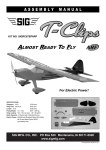
1
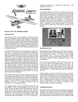
Wingspan: 49 in. (1245 mm)
Wing Area: 324 sq.in. (20.9 dm2)
Length: 32-1/2 in. (825.5 mm)
Flying Weight: 22 - 25 oz. (624 - 700 g)
Wing Loading: 9.7 - 11.1 oz./sq.ft. (30 - 33 g/dm2)
Radio Req.: 4 Channel, Mini Receiver,
4 Mini Servos
© Copyright 2012, SIG Mfg. Co., Inc.
In addition to providing the critical charging profile needed to
safely charge lipo batteries, a lipo battery charger also includes
the capability of "balancing" the available voltage in the cells, ensuring that the battery pack is at peak capacity at the end of the
charge cycle. This translates to better flight times and a longer
life from the battery pack.
RADIO EQUIPMENT
The RASCAL EP-49 gets its great flight performance from many
factors, but two of the most important factors are its lightweight
and generous wing area. The lighter the final weight is, the better
this airplane will fly! Since this model is factory built and covered,
you can only realistically control the finished, ready-to-fly weight
by choosing the most appropriate radio equipment for a model of
this size. In short, the flight performance of your RASCAL EP-49
will be directly controlled by the weight of the radio equipment you
choose to put in it. Maximum performance can only be achieved
with lightweight components.
INTRODUCTION
Congratulations on your purchase of the SIG RASCAL EP-49
ARF kit. The legend of the RASCAL began with a small rubberpowered free-flight model in the 1940s. Adapted for modern radio
control, the RASCAL's classic good looks and dream-come-true
flying characteristics have made it the favorite everyday airplane
of thousands of R/C pilots.
RECEIVER: A small or "micro" size receiver should be used in
this model due to weight and size constraints. In our flight tests
of the KADET EP-42B, we have used the following dual conversion receivers:
Weight
Receiver
FMA M5 FM
11 grams
Hitec Electron 6 FM
19 grams
Hitec Minima 2.4GHz
6.5 grams
SIG offers the RASCAL design in several sizes. This 49 inch
wingspan version blends the legendary RASCAL flying characteristics with a state-of-the-art brushless electric power system.
Included in the kit is a 2410-09 Brushless Outrunner Motor, 18
amp speed control (ESC), and a performance matched 8.5x8 EP
propeller. Add a 3-cell 850-1400 mah lipo battery pack and you
will have a marvelous little R/C ship with outstanding flight performance that is a pure joy to fly. And it's small enough to carry
around in your vehicle completely assembled and ready to fly almost anywhere, anytime!
SERVOS: "Standard" size servos (the ones that come with most
sport radio systems) are too big and too heavy for the RASCAL
EP-49. You will need smaller servos. In our flight tests of the
RASCAL EP-49, we have used the following servos.
Servo
Weight
Torque
Hitec HS-55
7.9 grams
15 in/oz
Airtronics 94091
9.0 grams
18 in/oz
Assembly of your RASCAL EP-49 ARF is fast and simple when
following the detailed instructions in this manual. A low parts
count and professional engineering ensure quick and easy assembly. All parts are CAD-drawn, laser-cut, and jig assembled,
which means that everything fits the way it should! We urge you
to read this instruction manual completely before starting assembly, to familiarize yourself with the parts and the assembly sequence.
NOTE: Any other brand of servo that is in the same size and
torque range will also work just fine.
SERVO CHORDS: You will need one Y-Harness Chord to connect the two aileron servos together. This allows you to operate
both aileron servos off of one receiver lead. Every radio manufacturer has Y-Harness Chords available for their radio systems.
Also, depending on exactly how long the wires are on your aileron
servos, you will most likely need two 6" Servo Extension Chords
to give you enough wire length to run through the wing.
ELECTRIC POWER SYSTEM
MOTOR (supplied): Your RASCAL EP-49 comes with a powerful
90-watt brushless motor, ready to easily and quickly install using
the directions in this assembly manual.
NOTE: In our prototype installations, we leave the single end of
the Y-harness plugged into the receiver permanently, and then,
unplug the two aileron servo extension chords from the Y-harness
when we remove the wing from the airplane.
ESC ELECTRONIC SPEED CONTROL (supplied): An 18 amp
Brushless type Electronic Speed Control is included. This ESC
is factory wired, with exception of the battery connector leads.
COVERING MATERIAL
Your RASCAL EP-49 is covered with ORACOVER®, a premium
quality covering made in Germany, and sold in the U.S. by
Hanger-9 as Ultracote®.
PROPELLER (supplied): A SIG 8-1/2 x 8 EP propeller is
furnished with this model. This propeller provides excellent flight
performance throughout the model's flight envelope.
Colors Used On Your Airplane
ORACOVER® #10 White (Ultracote® #HANU870)
and
ORACOVER® #29 Transparent Red (Ultracote® #HANU950)
or
ORACOVER® #39 Transparent Yellow (Ultracote® #HANU952)
BATTERY PACK (not supplied): The included motor and ESC
is designed to use 3S1P Lithium Polymer (LiPo) battery packs in
the 850-1400 mAh capacities. Properly charged, these packs deliver excellent power and duration for the RASCAL EP-49.
NOTE: As battery packs go up in capacity, so does their weight.
In turn, this can effect the recommended Center of Gravity location for this model. Use the pack size and capacity that best suits
the model in terms of the C.G. location. See the "Balance Your
Airplane" section of this manual for more details.
Wrinkles? After you remove the covered model parts from their
plastic bags, you may notice within the first couple days that some
of the covering material may become slack or wrinkled. If that's
the case, there is no need to be alarmed. The covering is not defective! Your RASCAL EP-49 was covered in a part of the world
that has consistently high humidity, and some of that moisture is
retained in the balsa wood when the parts were put in the bags.
BATTERY CHARGER (not supplied): FOR SAFETY AND
PERFORMANCE, CHARGE LITHIUM POLYMER BATTERIES
ONLY WITH A LITHIUM POLYMER BATTERY CHARGER!
2
❑
❑
❑
❑
❑
❑
❑
❑
When exposed to drier air, the wood loses the excess moisture,
dimensionally shrinking microscopically in the process. That's all
it takes to cause some slight relaxing of the covering, causing
wrinkles to appear.
Any wrinkles that appear in the covering are easy to remove by
applying a little heat from a small modeler's heat iron. Because
of this model's small size, we do not recommend using a heat gun
to tighten up loose covering. A typical hobby type covering iron
will work just fine. Even better is a small modeler's "trim seal" iron,
which is perfect for controlling the heat applied to a specific area.
Pin Vise for small diameter drill bits
Small T-Pins
Sandpaper
Hobby Knife with sharp #11 blades
Scissors
Covering Iron and Trim Seal Tool
Paper Towels
Rubbing Alcohol (for cleaning off excess epoxy glue)
KIT INVENTORY:
The following is a complete list of all parts contained in this kit.
Before beginning assembly, we suggest that you take the time to
inventory the parts in your kit.
First, use the tip of the hot iron to go over all the seams and color
joints in the covering, making sure they are all sealed down and
well adhered. Then, hold the hot iron over the wrinkle to lightly
shrink the material. Be very careful whenever working around
seams. Re-heating seams can cause them to "creep", making
them unsightly. A very easy way to avoid damaging seams and
joints when re-shrinking the covering is to protect the seams with
wet paper towels rolled into strips. These are placed directly onto
the seams and their coolness protects the seam from shifting or
"crawling" under heat. You must also be careful when using a heat
iron or heat gun when working around the window and windshield
areas - heat will distort these plastic pieces.
1 bag ❑ (1) Fuselage, with
Clear Plastic Windshield installed
Elevator & Rudder Pushrod Tubes installed
1 bag ❑ (1) Right Wing Panel with hinged Aileron
1 bag ❑ (1) Left Wing Panel with hinged Aileron
1 bag ❑ (1) Stabilizer & Elevator, hinged
1 bag ❑ (1) Fin & Rudder w/ hinges installed but not glued
1 bag ❑ (1) Plastic Cowling
❑ (7) M2 x 6 mm PWA Screws; for cowl mounting(4)
& motor mounting(3)
1 bag ❑ (1) Battery Hatch
❑ (1) Landing Gear Spreader
❑ (1) Plywood Wing Joiner
❑ (1) 3/4” x 1-3/4” Hook-&-Loop Tape (Velcro®)
❑ (1) M3 x 18mm Wing Mounting Bolt
1 bag ❑ (1) Right Aileron Servo Hatch
❑ (1) Left Aileron Servo Hatch
❑ (4) 6 x 10 x 12 mm Hardwood Servo Mount Blocks
1 bag ❑ (8) M2 x 8 mm PWA Screws for servo hatches
1 bag ❑ (1) Molded Clear Plastic Right & Left Side Windows
1 bag ❑ (1) 2.5mm dia. Formed Main Landing Gear Wire
1 bag ❑ (2) 1-3/4" dia. Main Wheels
1 bag ❑ (1) Right Wheel Pant
❑ (1) Left Wheel Pant
1 bag ❑ (2) Metal Wheel Pant Mounting Straps
❑ (4) M2 x 5.5 mm PWA Screws for straps
1 bag ❑ (1) Steerable Tailwheel Assembly w/ Tailwheel &
Brass Bearing Plate
❑ (2) M2 x 8 mm PWA Screws for tailwheel assembly
1 bag ❑ (4) Nylon Control Horns
❑ (4) Nylon Pushrod Keepers
1 bag ❑ (2) Wire Pushrods (short) w/ z-bend and adjustment
"V" in one end; for ailerons
❑ (2) Wire Pushrods (long) w/ z-bend and adjustment
"V" in one end; for elevator & rudder
1 bag ❑ (1) SIG 2410-09 Brushless Outrunner Electric Motor
with 18 amp ESC and Rubber Spinner
1 bag ❑ (1) SIG 8-1/2 x 8 EP Propeller, with Brass Hex Nut
& Aluminum Sleeve
1 bag ❑ (1) RASCAL EP-49 Decal Sheet
Recommended Temperatures:
To adhere the covering - 220OF - 250OF (104OC - 121OC)
To shrink the covering - 300OF - 320OF (149OC - 160OC)
REQUIRED TOOLS
For proper assembly, we suggest you have the following tools and
materials available:
NOTE: “PWA” refers to a screw or bolt with a phillips-head and an
integral washer flange.
❑ A selection of glues - Thin, Medium, and Thick SIG CA, and
SIG Epoxy Glue (5-minute and 30-minute)
❑ SIG Fine point CA Applicator Tips
❑ Screwdrivers
❑ Pliers - Needle Nose and Flat Nose
❑ Wire Cutters
❑ Soldering Iron & Flux
❑ Drill with Assorted Drill Bits
❑ 1.5 mm Hex Wrench or Ball Driver
NOTE: In this manual, any references to right or left, refer to your
right or left as if you were seated in the cockpit of the airplane.
WING ASSEMBLY
From the kit contents locate the Right and Left Wing Panels and
the Plywood Wing Joiner. You will also need epoxy glue, epoxy
mixing supplies, paper towels, and rubbing alcohol.
3
❑ 1) For maximum strength, we recommend using SIG Epoxy
Glue for joining the wing panels in this step.
a) Trial fit both wing panels together, without glue, on the plywood wing joiner to familiarize yourself with the assembly. Then,
take back apart.
b) Mix up a small amount of epoxy glue. Use a wire or stick
to quickly coat the inside of the wing joiner slot in the end of the
right wing panel. Also, coat the right half of the plywood wing
joiner with glue. Push the plywood wing joiner all the way into the
slot in the right wing panel. Hold the wing joiner in place until the
glue dries, wiping off any excess glue that oozes out of the joint.
c) Mix up a batch of epoxy glue. Use a wire or stick to coat
the inside of the slot in the end of the left wing panel with glue.
Also, coat the stub of the plywood wing joiner, that is sticking out
of the right wing panel, and the bare wood end ribs of both wing
panels. Then, put the wing panels together. Squeeze the panels
tightly together, aligning the leading and trailing edges of the wing
panels with each other. Wipe off any excess glue that oozes out
of the joint with a paper towel soaked in rubbing alcohol. Hold or
tape the wing panels in proper position until dry.
At the rear, align the wing carefully on the fuselage, and then use
the metal M3 x 18mm PWA Bolt to secure the wing in place on
the fuselage. After checking the fit, remove the wing.
AILERON HOOKUP
For this section you will need the assembled Wing, (2) Aileron
Servos and appropriate Chords (see radio notes at beginning of
this book), (2) Short Formed Wire Pushrods, (2) Nylon Control
Horns, and (2) Nylon Pushrod Keepers.
❑ 3) Note that the ailerons are permanently hinged in place.
Give each aileron a gentle pull to the rear to double check that
they are securely glued.
❑ 4) The aileron servos will be mounted on the back (uncovered) side of the plywood Servo Hatches.
a) Center the servo control arm, and then hold the servo in position on the back of one of the hatches. Make sure that you have
the servos control arm centered in the pre-cut slot in the hatch centered both horizontally and vertically. It needs to be right in
the middle of the slot when at neutral!
b) Mark the bottom of the servo mounting lugs onto the hatch.
Also mark the sides of the servo case.
c) Use Medium CA or epoxy to glue two Hardwood Servo
Mounting Blocks in position on the hatch, right up against the lines
you drew on the hatch, as shown. Let dry.
d) Mount your servo to the hatch, using the screws that were
provided with the radio system. Be sure to drill pilot holes in the
mounting blocks before screwing the servo in place.
e) Set up and turn on your radio system to center the servo
and check servo travel. Check to see that the servo control arm
does not bind on the slot in the hatch at extremes of travel.
f) Repeat steps 4a) through e) to mount the other aileron servo
to the other hatch.
NOTE: If possible, get someone to help you with this step. An
extra set of hands makes the job much easier. While one person
holds the two wing panels together in correct alignment, the other
person can clean off the excess glue and tape the wing panels
tightly together.
❑ 2) Test fit the wing on the fuselage. Make sure the wing slides
all the way forward, snug against the back of the fuselage former.
NOTE: If you have a double-sided servo arm, cut off the side of
the arm that you won’t be using so that it cannot bind on the top
of covering when the servo and hatch are installed in wing.
❑ 5) Looking inside the aileron servo mount opening in the bottom of the wing, you will find a short length of scrap wood with a
string tied to it. The other end of this string is tied to another piece
4
of scrap wood in the round hole near the center of the wing. This
string is used to pull the aileron servo chord through the wing,
from the servo mount towards the center section, in the following
steps.
❑ 6) In this step we will install a Nylon Control Horn on the bottom of each aileron. Make sure the horn is directly in line with the
servo arm, and that the base of the horn is right at the front edge
of the aileron. Follow these steps.
a) First, with a sharp hobby knife or razor blade shorten the
pegs on the bottom of the
control horns, so the pegs
won’t poke through the covering on the top side of the
ailerons. Cut off half the
length of the pegs.
b) Hold the control horn
in correct location on the
aileron and when you have it in the correct position, press down
so the pegs on the bottom of the horn puncture through the covering and make a mark on the balsa aileron.
c) Drill a 1/16” dia. pilot hole into the aileron at both marked
locations. Do not drill completely through the aileron, just far
enough to accept the control horn pegs.
d) Use a sharp knife to remove the small strip of covering material between the two holes. Then, glue the nylon control horn in
place using thick CA glue. Apply a small amount of glue to the
two pegs and a small amount of glue to the bottom of the control
horn base itself. Firmly press the horn into the two pre-drilled
holes in the aileron, until the base bottoms out on the surface. If
any glue oozes out onto the covering, it can be easily removed
with SIG CA Debonder.
e) Repeat this process to mount the other aileron control horn.
a) Working on one aileron at a time, plug a 6" servo extension
chord onto the end of your aileron servo wire. Secure this connection with a piece of plastic tape.
b) With a needle nose pliers, grab hold of the scrap wood in
the servo mount opening. Gently break the wood loose from the
wing structure, and then pull the wood and string a couple inches
out of the opening. Untie the string from the wood piece, and retie it securely to the end of your aileron servo chord.
c) Now break loose the other end of the string at the center of
the wing, and carefully begin pulling the end of the aileron chord
down into the servo mount opening and through the wing. You
will encounter obstructions as the servo plug bumps into the rib
structure inside the wing. When you do, don't pull too hard on the
string! You will find that by gently tugging back and forth alternately on the string at the center and then on the servo chord at
the opening, that you can eventually work the plug past the obstructions. Keep feeding the servo chord through the wing until
the end plug comes out the hole at the center of the wing. Remove the string from the end of the servo chord. Tape the servo
chord to the wing surface so it cannot fall back into the hole.
❑ 7) In preparation for installing the aileron pushrods, center the
aileron servo output arms in neutral position. Also, secure the
ailerons in neutral position with small pieces of tape.
a) Working on one aileron at a time, slide one of the nylon
pushrod keepers over the plain unbent end of the aileron pushrod
wire.
b) Insert the Z-bend end of the aileron pushrod wire into the
outermost hole of the servo output arm (if the holes in your servo
arm are too small for the wire, drill out the holes with a #60 or
3/64" dia. drill bit).
c) Hold the pushrod wire against the side of the nylon control
horn and use a fine tip pen to mark the exact position of the control horn hole on the wire. NOTE: The wire will be installed in the
2nd hole from the end of the horn.
d) Mount the aileron servo in the wing, using the screws that
came with the servo.
e) Repeat steps 5a) through d) to install the other aileron
servo in the other wing panel.
5
❑ 9) Note that the bottom of the stabilizer is the side without any
white covering. Mount a nylon control horn on the bottom of the
RIGHT elevator, as follows:
a) Two holes are pre-drilled in the right elevator, under the covering material, for the control horn mounting. Puncture the covering material directly over these two holes, on the BOTTOM of
the elevator only, to accept the two pegs of the control horn.
b) Use a sharp knife to remove the covering material around
the two holes, where the control horn will sit.
c) Glue the nylon control horn in place on the BOTTOM of the
elevator, using thick CA glue. Apply a small amount of glue to the
two pegs and a small amount of glue to the bottom of the control
horn base itself. Firmly press the horn into the two pre-drilled
holes in the elevator, until the base bottoms out on the elevator
surface. If any glue oozes out onto the covering, it can be easily
removed with SIG CA Debonder.
d) Use a pair of pliers to grasp the pushrod wire at the mark
just made, and then bend the plain end of the wire 90O towards
the center of the wing. Make the bend as sharp as possible.
e) The excess length of pushrod wire can now be cutoff, leaving a 3/16" end leg to pass through the control horn hole. Use a
good sharp pair of wire cutters to do this. Clean off any burs on
the end of the wire, caused by the cutting.
f) Insert the bent end of the pushrod wire into the hole in the
control horn. Slide the nylon pushrod keeper up to the control
horn and snap its tab end over the exposed wire on the opposite
side of the control horn.
g) Remove the pieces of tape holding the aileron in neutral
position.
h) Repeat these steps to bend and install the other aileron
pushrod on the other side of the wing.
❑ 10) Next the horizontal stabilizer/elevator assembly will be
glued permanently onto the fuselage. To allow enough time to
properly align the stabilizer, we recommend using slow drying SIG
Epoxy Glue for this step.
a) First mount the wing onto the fuselage. Place the model on
a flat surface that lets you view it directly from the front.
b) Set the stabilizer in place on the fuselage. Use a small
weight or pins to hold the stabilizer in position. View the model
from the front to see if the stabilizer is properly aligned with the
wing and fuselage, without tilting to one side or the other. If necessary, take the stabilizer back off and make slight adjustments
to the fuselage where the stabilizer sits, with a sanding block, until
the stabilizer will sit level.
NOTE: Later, when you turn on your full radio system for the first
time, you may find that the length of the aileron pushrod wires did
not come out exactly perfect, leaving the ailerons slightly out of
neutral position. If so, you can make small corrections to the overall pushrod length by tweaking the V-shaped adjustment bend that
is provided in the pushrod wire.
TAIL SURFACES AND TAILWHEEL
For this section you will need the Fuselage, the Stabilizer/Elevator
Assembly, the Fin/Rudder Assembly, the Tailwheel Assembly, and
(2) Nylon Control Horns.
❑ 8) Hold one of the white plastic control horns up against the
edge of the elevator. Use a fine tip pen to mark the two pegs on
the base of the control horn for cutting off just below the top covering of the elevator. Then, use a sharp razor blade or hobby knife
to cut off the pegs at the marks.
c) Remove the stabilizer. Mix a small amount of epoxy glue
and apply it to the mating surfaces of the fuselage and bottom of
the stabilizer. Carefully place the stabilizer back on the fuselage.
Again, use pins or a small weight to hold it in perfect position.
Make sure the stabilizer is square with the fuselage by measuring
from the trailing edge of the wing back to the trailing edge of the
stabilizer, on both sides. Shift the stabilizer slightly if necessary
until both measurements are the same. Wipe off any excess glue
using a paper towel or rag soaked in rubbing alcohol. Allow the
glue to dry thoroughly before unpinning.
6
❑ 12) Glue the tailwheel assembly in place in the leading edge
of the rudder.
❑ 13) Mount a nylon control horn on the left side of the rudder.
a) Shorten the pegs on the bottom of the control horn like you
did for the elevator horn back in Step 8.
b) Two holes are pre-drilled in the bottom of the rudder for the
control horn mounting. The holes are underneath the white covering and a little hard to see, but if you press down firmly on the
covering material with your finger, and then look very closely, you
should be able to find the location of the holes. Once you have
located them, puncture the covering material directly over the
holes, on the LEFT side of the rudder only.
c) Use a sharp knife to remove the covering material around
the two holes, where the control horn will sit (see photo back in
Step 9 of the elevator horn mounting).
d) Glue the nylon control horn in place on the LEFT of the rudder with thick CA glue. Apply a small amount of glue to the two
pegs and a small amount of glue to the bottom of the control horn
base itself. Firmly press the horn into the two pre-drilled holes in
the rudder, until the base bottoms out on the rudder surface. If
any glue oozes out onto the covering, it can be easily removed
with SIG CA Debonder.
❑ 11) Note that the fin and rudder are hinged together, but the
hinges are not glued. Pull the fin and rudder apart and set the
rudder aside for now, while we glue the fin in place on the fuselage.
a) Test fit the fin on the fuselage to get familiar with its proper
location. The back edge of the fin should line up perfectly with the
back end of the fuselage.
b) Carefully remove the covering from the top of the fuselage
where the front of the fin will set. Use a new sharp blade and be
careful not to cut into the wood of the fuselage.
❑ 14) The rudder can now be permanently hinged onto the back
of the fin and fuselage.
a) Start by taking a hobby knife and making a single slit in the
rear end of the fuselage, just below the stabilizer, where the bottom rudder hinge will go.
c) Glue the fin in place on the fuselage, being careful to line it
up squarely and perpendicular to the stabilizer. Let dry.
b) Insert the three CA hinges into the leading edge of the rudder. Push them in halfway.
c) Now carefully slide the exposed half of the hinges into the
slots in the back of the fin and fuselage. You will find it easiest to
insert the hinges at angle, one hinge at a time, instead of trying
to push all three of them straight in at once. Try to keep the hinges
approximately halfway into each part, but don't be overly concerned if they aren't perfectly straight and centered in the slots close is good enough.
d) To set the proper amount of gap between the Fin and Rudder, simply deflect the Rudder to the maximum amount of travel
needed. This will automatically set the proper hinge gap! Keep
7
ELEVATOR & RUDDER HOOKUP
For this section you will need the Fuselage, (2) Servos, (2) Long
Formed Wire Pushrods, and (2) Nylon Pushrod Keepers.
❑ 16) Mount the elevator and rudder servos in the fuselage,
using the screws that came with the servos.
a) Begin by positioning the servos in place in the plywood
servo tray built into the fuselage. Make sure the ends of the servo
arms line up with the plastic pushrod tubes already installed in
the fuselage.
b) Once you have the servos correctly positioned, drill small
pilot holes through the plywood for each servo mounting screw.
We used a small pin vise and a .040" (#60) drill bit to make these
pilot holes. Then, use a small screwdriver to install the servo
mounting screws.
in mind that for best control response the gap should be kept as
small as possible, but big enough to allow full movement of the
control surface. Make sure everything is functioning properly before proceeding to the next step.
e) Carefully place three or four drops of Thin CA glue directly
onto the hinge in the gap. You will notice that the glue is quickly
wicked into the slot as it penetrates both the wood and the hinge.
Turn the part over and glue the other side of the hinge. Continue
this process until you have glued both sides of all three hinges.
Keep a rag handy to wipe off any excess Thin CA glue. (If you
get some glue smears on the plastic covering, don't worry about
them right now. Once all the hinging is done, you can clean the
smears off the covering with CA Debonder). Let the glue dry a
minimum of 5 minutes before flexing the hinges.
❑ 17) Study the following photo to become familiar with the installation of the formed pushrod wires. Notice that the Z-bend in
the end of the pushrod will be installed down through the top of
the servo arm.
a) Now slide the pushrod wires inside the appropriate plastic
pushrod tubes in the fuselage.
b) Remove the servo arms from the servos. Install the servo
arms on the Z-bend ends of the pushrod wires (if the holes in your
servo arm are too small for the wire, drill out the holes with a #60
or 3/64" dia. drill bit). Then, reinstall the servo arms back onto the
servos. Do not tighten the servo arm screws completely yet because the arms may have to be repositioned when the radio system is tested and centered.
VERY IMPORTANT: It's critical that you only make one application of glue to each side of a CA Hinge. If you apply additional
glue to the hinge after the first application of glue is already dry,
the second application of glue will merely puddle in the hinge gap
and make the hinge too stiff to operate properly. When properly
glued, the portion of the hinge that you can see in the hinge gap
should have a dry appearance, not wet. Two to three good size
drops of Thin CA should be about the right amount. NEVER USE
CA ACCELERATOR ON CA HINGES!
❑ 15) Screw the Brass Bearing Plate of the tailwheel assembly
in place on the bottom of the fuselage, using the (2) M2 x 8mm
PWA Screws provided. Drill pilot holes first.
❑ 18) Next step is to complete the aft end of the rudder pushrod.
Start by centering the rudder servo output arm in neutral position.
Use small pieces of tape to hold the rudder in neutral position.
a) Slide one of the nylon pushrod keepers over the aft end of
the rudder pushrod wire.
b) Hold the rudder pushrod wire against the side of the nylon
control horn and use a fine tip pen to mark the exact position of
the control horn hole on the wire. NOTE: The wire will be installed
in the middle hole of the control horn.
8
c) Use a pair of pliers to firmly grasp the pushrod wire at the
mark just made, and then bend the plain end of the wire 90O
DOWNWARDS (so that the pushrod wire comes into the control
horn from the top - see photo below). Make the bend as sharp as
possible.
d) The excess length of pushrod wire can now be cutoff, leaving about a 3/16" end leg to pass through the control horn hole.
Use a good sharp pair of wire cutters to do this.
e) Insert the bent end of the pushrod wire in the hole in the
control horn, from the bottom. Then, slide the nylon pushrod
keeper up to the control horn and snap its tab over the exposed
end of the pushrod wire.
f) Remove the tape holding the rudder in neutral position.
❑ 21) Look inside the wheel pants for the built-in plywood mounting plates. This is how you identify which wheel pant goes on the
RIGHT side of the airplane and which goes on the LEFT side. The
plywood plates must be on the side of the wheel pant that is up
against the landing gear wire.
g) Repeat Step 18 to complete the aft end of the elevator
pushrod. Note that this pushrod is installed in the bottom hole of
the control horn.
a) The wheel pants must first be correctly aligned to the fuselage, before mounting. This is done by slipping the wheel pants
in place over the landing gear wires (without installing the wheels)
and then propping the rear of the fuselage up 3" off of a flat surface. With the wheel pants sitting on their flat bottoms, this provides the correct side view alignment for the next step.
NOTE: Later, when you hook up and turn on your full radio
system for the first time, you may find that the length of the
elevator and rudder pushrods did not come out exactly perfect,
leaving the control surface slightly out of neutral position. If so,
you can make small corrections to the overall pushrod length by
slight tweaking of the "V-shaped adjustment bend" that is near the
servo end of the pushrod.
MAIN LANDING GEAR
For this section you will need the Fuselage, formed Main Landing
Gear Wire, (2) Main Wheels, Landing Gear Spreader, Left Wheel
Pant, Right Wheel Pant, (2) Wheel Pant Mounting Straps, and (4)
M2 x 5.5mm PWA Screws.
❑ 19) The main landing gear wire is now glued in place in the
fuselage. We prefer 5-minute epoxy glue for this step.
a) First test fit the landing gear wire in place in the fuselage,
sliding the top of the wire into the slots built inside the fuselage to
receive it. The wire should slide in easily, all the way in until it bottoms out in the slots.
b) Remove the gear from the fuselage and use coarse sandpaper to sand the wire everywhere it will contact the fuselage
sides. Then wipe the wire clean with a rag soaked in rubbing alcohol or paint thinner. This will improve adhesion of the glue.
c) Apply 5-minute epoxy into each landing gear slot on the inside of the fuselage - just enough to fill the slots. Once again slide
the landing gear wire in place into the fuselage. Carefully wipe
off any excess glue with a rag soaked in rubbing alcohol. Let dry.
b) Press one of the metal wheel pant mounting straps in place
on one of the wire landing gear legs, up tight against the wheel
pant. Slide the strap up or down on the wire until the bolt holes
are approximately 3/8" above the axle hole. Use a sharp pencil
to mark the location of the mounting strap’s two bolt holes onto
the wheel pant. Do the same for the other wheel pant.
❑ 20) Epoxy the covered plywood landing gear spreader in place
on the bottom of the fuselage, between the wire landing gear legs.
Glue it everywhere it contacts the fuselage - on both ends and
long the front edge. Wipe off any excess glue with a rage soaked
in rubbing alcohol. Let dry.
9
c) Remove the wheel pants from the axles. Drill .046” dia.
(3/46” or #56 bit) pilot holes completely through the wheel pant
wall and the plywood pad inside, at the marks just made.
❑ 22) Assemble the wheel pants and wheels simultaneously onto
their axles, using the M2 x 5.5mm screws provided.
❑ 25) Using (3) M2 x 6 mm PWA Screws, mount the aluminum
motor mount to the firewall.
a) First mark the locations for the three mounting screws on
the face of the firewall. Notice that there is a 5/16” dia. hole in the
firewall, which marks the proper thrust line for the motor. Note
that there is also a larger circle etched into the firewall, centered
on the 5/16” hole. The etching represents the outer diameter of
the supplied motor mount. Hole the motor mount in proper location on the firewall and mark the screws positions with a pencil.
MOUNTING THE MOTOR & SPEED CONTROL
For this section you will need the Fuselage, the Brushless Electric
Motor, the Speed Controller (ESC), (3) M2 x 6mm PWA Screws,
and a portion of the “Hook-&-Loop Tape” (Velcro®).
❑ 23) Prepare the motor shaft to accept the propeller. In the
small parts bag that came with the Motor and ESC, locate the (2)
M3 Lock Nuts and (1) M3 Flat Metal Washer. Thread one of the
lock nuts onto the motor shaft in reverse direction - plastic insert
first, leaving the hex end pointing forward. Thread this nut all the
way onto the shaft until you run out of threads, as shown. After
that, slip the flat washer onto the motor shaft, and then screw the
remaining lock nut onto the end of the shaft - with it’s hex end
going on first. The propeller will be put on later. The other hardware in the small parts bag is not needed for this installation.
b) Drill .046” dia. (3/46” or #56 bit) pilot holes completely
through the firewall at the marks just made.
❑ 24) There are two small set screws holding the motor mount
on the back of the motor shaft. Use a 1.5mm hex wrench or balldriver to loosen the two set screws far enough to allow you to pull
the mount off of the shaft.
c) Screw the motor mount to the firewall with the three M2 x 6
mm PWA Screws. After running the three screws fully in place
10
the first time, we suggest removing them and "hardening" the
threads in the plywood with a drop of thin CA glue. Once the glue
has set, put the mount back in place and tighten the screws firmly.
RECEIVER & BATTERY INSTALLATION
For this section, you will need the remainder of hook-and-loop
tape, your receiver, the aileron Y-Harness, and a charged flight
battery pack.
❑ 26) Reinstall the brushless motor into the motor mount. Insert
the back end of the motor shaft into the mount, and then use a
1.5 mm wrench to tighten the two set screws.
❑ 30) You can mount the receiver either on the top or bottom of
the plywood cabin floor, using a piece of hook-and-loop tape to
keep it in place. We mounted ours on the bottom.
❑ 31) Plug the aileron Y-harness into the aileron slot of your receiver. Plug the elevator and rudder servo leads into their correct
slots. Also plug the ESC into the throttle slot in the receiver. (Your
radio manual will tell you which slots to use in your receiver).
❑ 27) Before the ESC is installed, the red (positive) and black
(negative) battery wires coming out of the ESC must have a
proper battery plug installed. The battery plug is not included in
this kit - there are various types available, so it is a matter of personal preference. We like to use the “Deans Ultra” plug, as shown.
❑ 32) Exactly where you should locate your battery pack will depend on the final balance of your airplane. Every airplane (especially balsa wood models) can vary in balance. You won’t know
exactly where to put your battery pack until the airplane is completed, and you check the final balance on page 14 of this manual.
There is plenty of room inside the Rascal EP-49 fuselage to accommodate practically any balance situation. The battery pack
can go all the way forward against the back of the firewall, or back
in the cabin behind the landing gear (in which case you would relocate the receiver to the top of the plywood cabin floor. In most
cases we believe you will find, like we did, that the battery pack
will end up on the floor of the nose compartment, as shown in the
next photo. Use a section of hook-&-loop tape (Velcro®) to hold
it in place during flight. Make sure that the battery plug is in position to be easily plugged into the ESC.
Solder the battery plug on to the red (positive) and black (negative) wires of the ESC, being mindful of the polarity. Solder the
mating connector to your flight pack battery, again being careful
to get the polarity correct.
❑ 28) Connect the ESC up to the motor - red wire to red wire;
white to white; black to black. Later, when running the motor for
the first time, if you find that the motor is turning in the wrong direction, simply switch two of the wires to change the direction of
rotation.
❑ 29) Mount the ESC inside the nose compartment of the airplane. Use a section of the supplied sticky-back “Hook-&-Loop
Tape” (Velcro®) to hold the ESC in place. We mounted our ESC
up high on the right fuselage side, as shown in the next photo.
11
SYSTEM TESTS
The completed radio and motor systems can now be powered up,
then tested and adjusted for proper operation. Note that the wing
and propeller are NOT yet installed at this point.
❑ 33) Make sure the aileron, elevator, and rudder trim levers on
your transmitter are each in neutral position and that the throttle
stick is in the full "low throttle" position.
a) Turn on your transmitter. NOTE: The transmitter MUST ALWAYS be turned on first and turned off last!
b) Plug the battery pack into the ESC. You will hear an audio
tone from the ESC, indicating that is recognizing the signal from
the transmitter.
c) The elevator and rudder servos should now be working. If
necessary, reposition the servo output arms on the elevator and
rudder servos as close to 90O to the servo case as possible. Be
sure to reinstall the output arm retaining screws after making the
adjustment.
d) Move the elevator stick on the transmitter to check for the
correct direction of elevator movement. If necessary, use the
servo reversing feature in your transmitter to reverse the direction.
Repeat this same procedure for the rudder servo.
e) With the rudder and elevator servos now moving in the correct directions, check the neutral positioning of the rudder and elevator surfaces. If needed, adjust the V-bend in the pushrods to
properly center these surfaces.
NOTE: Control surface travel measurements are always taken at
the widest part of the control surface, at the trailing edge.
RECOMMENDED CONTROL SURFACE TRAVEL
Ailerons: 5/16" Up - 5/16" Down
Elevator: 3/8" Up - 3/8" Down
Rudder: 1/2" Right - 1/2" Left
COWLING & COOLING
❑ 37) From the kit contents, locate the plastic Cowling and (4)
M2 x 6 mm PWA Screws.
a) Slide the cowling in place over the motor and onto the front
of the fuselage. Use pieces of tape to secure the cowling in place,
centered with the motor, with the front of the cowling about 1/4"
behind the front face of the 3.5 mm lock nut on the motor shaft.
❑ 34) Set the wing in place on the fuselage, plugging the aileron
servo chords into the Y-Harness in the fuselage.
a) With the radio on, check the position of the aileron servo
output arms. If necessary, reposition the arms as close to 90O to
the servo case as possible. Be sure to reinstall the output arm
retaining screws after making the adjustment.
b) Move the transmitter aileron stick and check for correct direction of aileron movement. If needed, use the servo reversing
feature in the transmitter to reverse the direction.
c) With the aileron servos now moving in the correct directions, check the neutral position of the ailerons. If needed, adjust
the V-bend in the pushrods to properly align both ailerons in the
neutral position.
b) Use a sharp pencil or a pointed object, such as an awl, to
mark or punch a centered mark in one of the cowl mounting holes.
Use a small (.040") dia. bit to drill a pilot hole through the fuselage
side at the mark just made. Use a screwdriver to install one of
the M2 x 6 mm PWA Screws into the drilled hole.
c. Re-check the placement of the cowling to make sure it hasn’t
shifted, and then again use a sharp object to mark the center of
the opposite cowl mounting hole. Drill a pilot hole and install another mounting screw in this hole.
d. Repeat this process until all four mounting screws are in
place. Then remove the tape.
❑ 35) For safety, the propeller and spinner should NOT be installed on the motor for this step, which is the first test of the power
system.
a) Slowly advance the throttle stick on the transmitter. The
motor should start turning. If not, perhaps your throttle channel
needs to be reversed on the transmitter. If this is the case, unplug
the flight battery first, and then reverse the throttle direction in your
transmitter. To continue, plug the battery back into the ESC.
b) Again slowly advance the throttle stick. The motor should
begin turning in proportion to the amount of throttle stick movement. Now, make sure the motor shaft is moving in the correct
direction. When viewing the fuselage from the rear to the front as if you were sitting in the cockpit - the motor shaft should turn
clockwise, when throttle is applied. If your motor is turning in the
wrong direction, double check that you have the red, black, and
white wires from the motor to the ESC plugged in correctly. If they
are correct (red to red, black to black, white to white), and the
motor still turns the wrong direction, simply switch two of the wires
to change the direction of rotation (make it red to black, and black
to red).
e) Remove the cowling and harden the holes in the fuselage
side with a drop of Thin CA. Let dry completely.
❑ 38) In order to properly cool the motor, ESC, and battery pack
in flight, we need to let some air flow into the cowling. This is done
by making one (or more) holes in the front of the cowling. The
exact shape and location of the hole(s) is not critical. Here are
two different styles of intake air holes that we have used on this
airplane.
Style 1: On one of our prototype models we cut three 1/8" x 11/4" slots in the front slope of the cowling, as shown in the next
two photos. The slots are spaced 3/8" apart. You can use a
Dremel® tool, or a simple hobby knife to make the slots. Finish
the edges of the slots with fine sandpaper.
CONTROL SURFACE TRAVEL
❑ 36) The maximum distance that a control surface moves when
you move the transmitter stick to full deflection is normally called
the control surface “travel" or “throw”. Most modern radio systems
allow you to adjust the control travel of the servos directly from
the transmitter. This radio feature is usually referred to as EPA
(meaning End Point Adjustment). Use this feature to adjust the
control surface travel for the ailerons, elevator, and rudder of your
RASCAL EP-49. The following control travel measurements are
recommended for your initial test flights of the airplane.
12
MOUNTING THE PROPELLER & SPINNER
❑ 40) Locate the Propeller with Brass Hex Nut and Aluminum
Sleeve, plus the rubber Spinner from the kit contents.
a) Remove the front M3 lock nut and the washer from the
motor shaft. Then thread the Brass Hex Nut that came with the
propeller onto the motor shaft. Thread it all the way back, up tight
against the rear lock nut. Tighten it securely. (If you have some
Locktite® thread locking compound, put a drop between the two
nuts before you tighten them together.)
b) A short section of aluminum tubing is provided with the propeller to sleeve down the hole in the prop hub to the same diameter as the prop shaft. Press the aluminum sleeve into the center
hole of the prop, as shown. It's a tight fit, but it will go in.
Style 2: On a second prototype we simply enlarged the hole
in the front of the cowling, where the motor shaft comes through,
to 1-1/4" diameter. This is slightly larger than the motor spinner
and will let in sufficient air to cool the power system.
c) Next slide the propeller in place onto the motor shaft. Notice
that the backside of the propeller hub has a hex shaped recess
the same size as the brass hex nut. Slide the propeller all the way
back, pressing it over the brass nut.
d) Place the flat metal washer back on the motor shaft, and
then thread the front lock nut in place against the washer and the
propeller. Tighten the nut securely.
❑ 39) Once the air gets inside the cowling it needs somewhere
to exit. Take a close look at the balsa battery hatch and you will
see that it has 3 holes already cut in it, but the holes are covered
over with white covering material. Take a sharp hobby knife to cut
away the covering over the holes. This will complete the cooling
air path. The air can now flow into the cowling, through the opening in the lower front of the fuselage under the cowl, and then exit
through three holes in the battery hatch, keeping a steady flow of
cooling air over the entire power system.
SAFETY WARNING: With the propeller mounted to the motor, it
is very important that you always be aware of the position of the
throttle stick on your transmitter whenever you plug the battery
pack onto the system, making the system "hot". The motor used
in this model is powerful enough to cause damage to people or
property if it is activated prematurely, accidentally, or unexpectedly. With an electric airplane, we recommend that you get in the
habit of always keeping the throttle stick in the "low throttle" posi13
tion, even when the transmitter is in storage. Be sure to recheck
the throttle stick position before plugging in the battery pack.
Under no circumstances should you hold this model by the nose
when the battery is plugged in. Never plug your battery pack onto
the system until; 1) your transmitter is ON with the throttle stick in
the low position, and 2) you are on the flight line, ready to fly.
BALANCE YOUR AIRPLANE
IMPORTANT: An R/C model should always be balanced with
everything on board, ready for flight. The flight battery must be
installed in the fuselage and the propeller and spinner must be
mounted in place when balancing the model.
Because the RASCAL EP-49 is a relatively small and light airplane, the single most effective adjustment you can make to
achieve correct balance is the weight of the battery pack and its
location. As mentioned in the beginning of this manual, we recommend 3S1P lithium-polymer (lipo) battery packs in the 8501400 mAh range. The difference in weight between these two size
battery packs can be as much as 1-1/2 ounces, making it an effective balancing tool. Battery packs in this range all provide
plenty of flight time, so we chose the pack that best balanced our
individual airplane. We suggest that you do the same thing.
SIDE WINDOW INSTALLATION:
From the contents of your kit, locate the molded side windows.
Use scissors to cut out each window, leaving about 1/8" of plastic
around the edges for a gluing surface. We suggest using 5-minute
epoxy or RC-56 glue to mount the windows into the inside of the
fuselage. DO NOT use thin CA glue for this step! Apply a thin
bead of glue to these edges and press the window in place from
the inside of the fuselage. Use small pieces of tape to hold the
windows in place until the glue sets.
RECOMMENDED BALANCE POINT
2” to 2-5/16"
Behind The Leading Edge Of The Wing
At The Fuselage Sides
Notice that the rear face of the main wing spar of the RASCAL
EP-49 is at the rear limit of the balance range. The simplest way
to check the balance of your RASCAL EP-49 is to place a fingertip, one on each side of the fuselage, at the main spar location on
the bottom of the wing. Slowly lift the airplane off the worktable
and note the attitude of the fuselage. The airplane should balance
on your fingertips in level position - not nose up or nose down. If
the nose hangs low, the model is "nose heavy". If the tail hangs
low, this means that the model is "tail heavy". If either of these
conditions exists, you must make adjustments to correct the problem. Never attempt to fly a model that is out of balance! Since
the battery pack is the single heaviest component in the airplane,
it can be used to adjust almost any tail heavy or nose heavy condition. This is simply done by moving the battery forwards or backwards inside the airplane, and/or going to a lighter or heavier
battery pack.
DECAL APPLICATION
The decals supplied with the RASCAL EP-49 are stickers with a
self-stick adhesive back. They are not water slide decals. Also,
these decals are not die-cut. Each design must be cut from the
sheet with a sharp #11 hobby knife or a sharp scissors.
Small decals can be easily applied to the model by simply removing the paper backing sheet, and then, laying the decal in position
and pressing it in place with your finger.
For the larger decals, such as the "RASCAL EP-49" wing decal,
we suggest the following "wet" method of application:
a) Carefully cut out the decal with a hobby knife.
b) Peel the paper backing sheet completely off the decal, being
careful not to let the sticky side double over and adhere to itself.
c) Use a product like SIG Pure Magic Model Airplane Cleaner,
Fantastic®, or Windex® to spray the adhesive side of the decal.
Also, spray the area of the model that will receive the decal.
d) Lightly place the decal onto the wet surface of the model.
The liquid cleaner solution will keep the decal from actually sticking to the model until you have had time to shift it around into exact
position. Once in position, use a piece of stiff cardboard (or sheet
balsa, thin plywood, or a SIG SH678 EPOXY SPREADER) to
squeegee the excess liquid out from under the decal. Squeegee
repeatedly, removing all excess liquid and any air bubbles. Mop
up the liquid with a paper towel. Allow to dry overnight.
e) When completely dry, wash off any soapy smears with a soft
clean wet rag.
FLYING YOUR RASCAL EP-49
The RASCAL EP-49 appeals to R/C fliers of all experience levels
-from beginners to expert pilots. Assuming that the expert pilots
will not need much guidance, these flying notes are written for the
R/C newcomer.
PRE-FLIGHT
Be sure your flight battery pack is fully charged. Also, be sure
your transmitter is fully charged. We highly recommend that you
perform a standard range check on your radio system - with and
without the motor running. Make sure your propeller is balanced
and has no nicks or cracks - never fly with a faulty propeller! Finally, take a few minutes to give your model a thorough pre-flight
inspection. Make sure everything is secure and tight and operating properly, before attempting to fly the model. Any problems you
have will not magically disappear in the air - they will get worse!
14
AN INSTRUCTOR CAN SAVE YOUR AIRPLANE!
If you are new to the hobby of flying R/C model airplanes, DO
NOT attempt to fly this model by yourself! We strongly urge you
to seek the help of a competent flight instructor. There are hundreds of R/C clubs in the U.S. and these clubs normally have designated instructors, who are eager to help newcomers. The
easiest way to find an R/C flying club in your area is to ask your
local hobby shop or check the AMA (Academy of Model Aeronautics) web site: www.modelaircraft.org .
is to line the airplane up with the center of the runway, facing directly into the wind. Advance the throttle smoothly to full high
throttle position. As the airplane accelerates, apply a little right
rudder input to counteract motor torque and keep the model tracking straight. When sufficient speed is attained, a small input of up
elevator will get the model airborne.
The RASCAL EP-49 can also be easily hand-launched if the grass
is too long at your flying field. When hand launching, the airplane
must be launched, straight and level directly into the wind, with
the nose aimed at a point on the ground about 75' in front of you.
Never launch the model with the nose pointed up or the wings
tipped to one side or the other. The launch should be firm enough
to achieve flight speed, but yet, not overly hard.
An R/C flight instructor serves two important functions. First, he
will test fly your new airplane to make sure it is performing correctly, before you try to fly it. These first flights are called "trim
flights". During these flights, the flight instructor will "trim" the
model from the transmitter to ensure that it flies straight and level
without any problems. When a brand new R/C model takes off for
the first time, there is no way of knowing which way it might go.
Some models will try to climb, while others may want to go down.
Some will try to turn left, others right. Some models will be doing
both at the same time! It doesn't mean that there is anything
wrong with the model, but these minor differences must be
"trimmed out" in order for the model to fly "hands-off" straight and
level. An experienced pilot can instantly correct out of trim conditions before the model crashes into the ground. An inexperienced
beginner has almost no chance of saving an out of trim model!
Once the airplane is in the air, it should be flown to a reasonable
altitude for flight trimming - approx. 100' or so. Flight trimming is
the use of the transmitter trim levers to make fine adjustments to
the position of the control surfaces, to make the model to fly
straight and level when you momentarily remove your fingers from
the control sticks. The ailerons, elevator, and rudder trim must all
be adjusted carefully to achieve ‘hands off” straight and level flight.
Once the ailerons and rudder are properly trimmed, future re-trimming of them is usually rare. The elevator on the other hand can
need re-trimming quite often, depending primarily on how fast you
set your cruising speed. You will quickly learn that every time the
throttle setting is changed, that of course changes the speed of
the airplane, and then the elevator trim must also be re-adjusted
to make the model fly level, instead of climbing or diving.
The second reason for an instructor is to have someone there to
correct the mistakes you will make during the learning process. It
isn't that flying an R/C model aircraft is all that difficult. It is more
a matter of learning what to do and when to do it. No matter how
slowly a model flies, an incorrect control input can produce almost
instant problems that, in turn, demand almost instant correction.
This is especially true at lower flight altitudes. A good flight instructor will climb your model to an altitude that gives him a good
chance of saving your airplane when you make these inevitable
mistakes. This altitude is generally referred to as "2 mistakes
high". When you get into trouble, quickly hand the transmitter
back to your instructor so he can rescue the airplane. He will get
it leveled off, and then, let you try it again. Without an instructor,
it is very likely that you would not receive this second chance.
Depending upon the altitude of your flying field, the condition of
your flight battery the amount of charge it is holding, and other
factors, you will most likely find that the RASCAL EP-49 can easily
cruise in level flight at 1/2 to 3/4-throttle setting. This reduced
throttle setting will slow the model down, increase your flight duration, and make the model easier to fly for beginners.
Beginning R/C pilots, almost always, over-control their models.
This is perfectly normal but a trait that must be cured during instruction. Another problem common to beginners is disorientation. For example, when the airplane is flying away from you, right
aileron input produces a right turn and left aileron input produces
a left turn. However, when the airplane is flying directly toward
you, the same right aileron input now makes the airplane turn to
YOUR left. The airplane is still turning to it's right, but that is now
your left side! This perceived control reversal is very confusing to
all first time R/C pilots! Without an experienced flight instructor
on hand, it will most likely cause the loss of the model.
Landing the RASCAL EP-49 is relatively easy. Flying into the
wind, line up with the center of the runway and gradually throttle
back. As the airplane slows down, the nose will drop, allowing the
airplane to glide down to the runway. If the glide is too steep and
the model is picking up speed, feed in a little up elevator until you
get a shallow glide at a constant speed. About a foot or so above
the ground, start to flare the landing by carefully feeding in more
up elevator a little bit at a time. This will bring the nose up, slowing
the airplane even more. Try to hold the airplane just inches off
the ground until it finally slows enough to settle smoothly onto the
runway.
With a flight instructor, these early learning problems can be easily
dealt with. The more you fly, the quicker you will learn. Soon you
will be flying "solo" with little thought of the moves required. It will
start to come easy. Remember the first time you tried to ride a bicycle? It seemed completely awkward the first time, but once you
learned how, it became easy. Don't get discouraged if you have
a minor crack-up. Repair the damage and get back into the air as
soon as possible.
FIRST TEST FLIGHT
Choose a calm day, with little or no wind, for the initial test flights.
This is important in getting the model properly trimmed. If there
is too much wind, you won't get a true reading on what the model
is doing in the air.
Caution: Never land your airplane in tall grass or weeds with the
motor running. Always throttle back completely if you land in such
terrain or if you nose over after landing. Tall grass or a nose over
will stall the electric motor if it is running. A stalled motor can overheat the ESC and batteries, causing them to fail.
The RASCAL EP-49 is capable of taking off from any smooth surface runway or a closely cut grass field - this is called an ROG
(Rise-Off-Ground) take-off. The correct ROG take-off procedure
GOOD LUCK AND HAPPY LANDINGS!
15
WARNING! THIS IS NOT A TOY!
CUSTOMER SERVICE
Flying machines of any form, either model-size or full-size, are not toys!
Because of the speeds that airplanes must achieve in order to fly, they
are capable of causing serious bodily harm and property damage if they
crash. IT IS YOUR RESPONSIBILITY AND YOURS ALONE to assemble
this model airplane correctly according to the plans and instructions, to
ground test the finished model before each flight to make sure it is completely airworthy, and to always fly your model in a safe location and in a
safe manner. The first test flights should only be made by an experienced
R/C flyer, familiar with high performance R/C aircraft.
SIG MFG. CO., INC. is committed to your success in both assembling
and flying the RASCAL EP-49 ARF. Should you encounter any problem
building this kit or discover any missing or damaged parts, please feel
free to contact us by mail or telephone.
SIG MFG. CO., INC.
P.O. Box 520
401 South Front Street
Montezuma, IA 50171-0520
JOIN THE AMA
PHONE: 1-641-623-5154
FAX: 1-641-623-3922
The governing body for radio-control model airplanes in the United States
is the ACADEMY OF MODEL AERONAUTICS, commonly called the
AMA. The AMA SAFETY CODE provides guidelines for the safe operation of R/C model airplanes. While AMA membership is not necessarily
mandatory, it is required by most R/C flying clubs in the U.S. and provides
you with important liability insurance in case your R/C model should ever
cause serious property damage or personal injury to someone else.
SIG WEB SITE: www.sigmfg.com
SIG E-MAIL: [email protected]
LIMIT OF LIABILITY
The craftsmanship, attention to detail and actions of the builder/flyer of
this model airplane kit will ultimately determine the airworthiness, flight
performance, and safety of the finished model. SIG MFG. CO.’s obligation
shall be to replace those parts of the kit proven to be defective or missing.
The user shall determine the suitability of the product for his or her
intended use and shall assume all risk and liability in connection therewith.
ACADEMY OF MODEL AERONAUTICS
5161 East Memorial Drive
Muncie, IN 47302
Telephone: (765) 287-1256
AMA WEB SITE: www.modelaircraft.org
If you like the Rascal EP-49, take a look at its “sister ship” - the Kadet EP-42B!
16