1
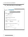
Camoplast Solideal Inc. 4162, Burrill - Local A Shawinigan, (Québec) G9N 6T6 CANADA E-mail : [email protected] Website : www.camoplastsolideal.com IMPORTANT Please read carefully each part of this document as well as model specific Installation Guidelines prior to assembling, installing and using the track system. IMPORTANT The way the Camoplast Hi-Performance Tracks Camoplast ATV T4S track system is used has a direct link with the longevity of the system components. Sportive driving, rapid direction changes and repeated fast turns (more specifically on power steering vehicles) are not advised. These driving styles increase risk of derailing and can cause premature wear and or major breakdowns on the track system which will not be covered under normal warranty. Original notice Other languages translation available at www.camoplastsolideal.com and MC are trademarks of Camoplast Solideal Inc. All rights reserved. ©2015 Camoplast Solideal Inc. Printed in Canada. ® TABLE OF CONTENTS INTRODUCTION . . . . . . . . . . . . . . . . . . . . . . . . . . . . . . . . . . . . . . . . . . . . . . . . 1 SAFETY . . . . . . . . . . . . . . . . . . . . . . . . . . . . . . . . . . . . . . . . . . . . . . . . . . . . . . . 1 GENERAL INFORMATION . . . . . . . . . . . . . . . . . . . . . . . . . . . . . . . . . . . . . . . . . 3 HINTS AND TIPS . . . . . . . . . . . . . . . . . . . . . . . . . . . . . . . . . . . . . . . . . . . . . . . . 3 USER NOTICE AND DISCLAIMER . . . . . . . . . . . . . . . . . . . . . . . . . . . . . . . . . . 4 USING THE ATV WITH TRACKS . . . . . . . . . . . . . . . . . . . . . . . . . . . . . . . . . . . . 6 INSTALLATION, REMOVAL AND RE-INSTALLATION . . . . . . . . . . . . . . . . . . . 16 ADJUSTMENTS . . . . . . . . . . . . . . . . . . . . . . . . . . . . . . . . . . . . . . . . . . . . . . . . 20 INSTALLATION OF A RUBBER TRACK . . . . . . . . . . . . . . . . . . . . . . . . . . . . . 35 BREAK-IN PERIOD . . . . . . . . . . . . . . . . . . . . . . . . . . . . . . . . . . . . . . . . . . . . . 38 REPLACEMENT OF A WHEEL WITH EXTRACTOR . . . . . . . . . . . . . . . . . . . 39 MAINTENANCE SCHEDULE . . . . . . . . . . . . . . . . . . . . . . . . . . . . . . . . . . . . . . 41 LUBRICATION . . . . . . . . . . . . . . . . . . . . . . . . . . . . . . . . . . . . . . . . . . . . . . . . . 45 STORAGE . . . . . . . . . . . . . . . . . . . . . . . . . . . . . . . . . . . . . . . . . . . . . . . . . . . . 51 WEAR . . . . . . . . . . . . . . . . . . . . . . . . . . . . . . . . . . . . . . . . . . . . . . . . . . . . . . . . 52 2-YEAR LIMITED WARRANTY . . . . . . . . . . . . . . . . . . . . . . . . . . . . . . . . . . . . 57 TROUBLESHOOTING . . . . . . . . . . . . . . . . . . . . . . . . . . . . . . . . . . . . . . . . . . . 60 SERIAL NUMBER LOCATION . . . . . . . . . . . . . . . . . . . . . . . . . . . . . . . . . . . . . 61 ’’CE’’ DECLARATION OF CONFORMITY . . . . . . . . . . . . . . . . . . . . . . . . . . . . 63 PARTS LIST . . . . . . . . . . . . . . . . . . . . . . . . . . . . . . . . . . . . . . . . . . . . . . . . . . . 66 1099-01-1015 - VERSION D INTRODUCTION INTRODUCTION Thank you for choosing the Camoplast T4S, a Camoplast Hi–Performance ATV Track System, (hereinafter referred to as the "System"). You have made the right choice. This system will provide you with all the traction, performance and durability you require for recreational or work purposes and allows for year–round operation. This track system for quads (hereinafter referred to as "ATVs") provides exceptional floatation with very low ground pressure. Its strong lightweight steel frame (30 kg), its internal sprockets, adapted to the vehicle’s capacity, and its track, specifically designed for ATVs, make it the best system on the market. SAFETY This guide uses the following symbols to emphasize particular information : WARNING Indicates a potentially hazardous situation which, if not avoided, could result in death or serious injury. CAUTION: Indicates a potentially hazardous situation which, if not avoided, may result in damage to vehicle components. NOTE: Indicates supplementary information. 1 SAFETY On track system frames, you will find the following warning sticker: . USER MANUAL - Every user must read the User Manual before attempting to operate a vehicle equipped with track systems. If track systems are sold or in any way tranferred to a new user, the User Manual must also be transferred to the new user. MOVING PARTS - Hands or fingers caught between moving parts of the equipment present a danger to life or limb. Turn motor off before servicing track systems. "MAINTENANCE SCHEDULE" SECTION OF USER MANUAL - Follow instructions contained in the Maintenance Schedule section of the User Manual to ensure safe and long–lasting operation of track systems. 2 GENERAL INFORMATION GENERAL INFORMATION All figures, information or photos presented in this document are up to date at the time of publication. However, they may change without notice. Read and follow indications of the ATV user manual and installation guidelines carefully. Their contents remains applicable after installating of the System. This document should be read by every person who drives the ATV equipped with the System. This document is an integral part of the System. Pass it along to any new System owner. Consult legal authorities where you drive your ATV equipped with the System before usage to ensure that you respect all applicable laws and regulations. ATV track systems are designed to reduce ground pressure and increase vehicle traction. However, during normal operating conditions, vehicle speed will be reduced, compared to a wheeled vehicle. HINTS AND TIPS Before leaving for an excursion, make sure you have the following within arms reach : 12 mm, 14mm, 16 mm, 15 mm, 17 mm, 19 mm and 30 mm wrenches, one axe, one shovel, one tow cable, a lifting jack and one adjustable wrench. Generally, the slower you go, the better the traction will be. For riding or excursions in unknown, or remote terrain, make sure you have a cellular phone or satellite phone, a first aid kit and spare parts in your possession. When driving off trails, always be cautious to the presence of hidden obstacles. When driving in deep snow, do not intentionally spin the track (tracks keep on turning while the vehicule does not).This could cause the vehicle to get stuck. 3 USER NOTICE AND DISCLAIMER USER NOTICE AND DISCLAIMER The Camoplast T4S System was initially designed to be used in winter conditions and was then adapted to be used in fall and spring conditions. This document holds important information regarding driving an ATV equipped with the Camoplast T4S System by Camoplast Hi-Performance Tracks. It is mandatory that every user takes the time to carefully read, understand and then consult this reference manual and user guide as well as the ATV owner's manual as needed. When purchasing either a new or used track System, the user must obtain all documentation related to the System, including manuals and guides related to the ATV on which the System is installed. If need be, contact the Camoplast Hi-Performance Tracks products dealer nearest to you to obtain any additional information. You may also consult the Camoplast Solideal Web site at www.camoplastsolideal.com and call our technical support by email at [email protected]. Camoplast Hi-Performance Tracks believes that there are certain risks related to the installation and use of the System. Our experience shows that the System is safe. However, the user must be aware of the risks related with driving an ATV with the particularities of this type of System. The ATV driver must, at all times, respect all applicable laws and regulations, the indications of the System manufacturer and the indications from the vehicle manufacturer fixed by law, namely when age restrictions exist and ATV base equipment is required (headlights, flashers and brake lights, rearview mirror, etc.). The user must always wear adequate safety equipment, such as a helmet, safety glasses (or visor), protective clothing, boots and gloves. It is understood that driving while impaired or intoxicated presents a danger for the ATV user and others and is against the law. The System consists of many moving parts, including transmission wheels. If an object lodges itself or becomes jammed into the System and blocks the track, it is mandatory to stop the engine and the vehicle and apply the security brake before removing object said. By avoiding to do so, the user exposes himself to sudden movement of the ATV or to breakage of a part or component coming from the System, which could cause severe injuries. It is also very important to wear full length clothing and always avoid hanging or stringy accessories. Driving an ATV equipped with such a System requires particular precautions and a knowledge of proper driving techniques of such vehicles. An evaluation by the user of the conditions and terrain (state of the ground, grade of hill, density of snow, etc.) is equally essential. 4 USER NOTICE AND DISCLAIMER An ATV equipped with a System cannot compete and/or be used to perform stunts, acrobatics or other exploits, as these could result in loss of control or severe injuries. Insufficient knowledge of an ATV during down hill riding, climbs and crossing of obstacles and turns can result in tipping or roll over, and can cause severe injuries. Carrying a passenger, a load or attaching a tow can cause the ATV to be less stable, and affect driveability. Unless otherwise prescribed by law and by the ATV manufacturer, you must not carry a passenger, loads or tow any objects. The installation of a System: • Increases ground clearance. • Changes the center of gravity. • Increases the ATV width and weight. • Reduces ground pressure. These parameters will effectively change driving characteristics of an ATV equipped with the System. Consequently, it is highly recommended that the user adapt his driving style to the new characteristics mentioned above. The driver must always use caution when he crosses obstacles, circulates through narrow paths, meets vehicles coming in the opposing direction, etc. As it was designed, the System will considerably reduce the ATV top speed and can falsify the speedometer. Generally, the System transmission wheel diameter is less than that of the tire. Therefore, the vehicle speed will be less than that actually displayed. Whether the ATV is equipped or not with the System, users must always adapt the speed to actual driving conditions. Users must never exceed speed limits or drive faster than their capacities allow. Excessive speed remains one of the main causes of severe accidents on ATVs. Camoplast Hi-Performance Tracks is proud to offer ATV conversion kits within its wide range of products. ATV Track Systems are not only reliable, but safe. However, there are risks inherent to driving an ATV equipped with the System. It is therefore very important that any driver familiarizes himself with proper driving techniques of an ATV equipped with a System, and that he adapts his driving to his level of experience and continually evaluates operating conditions and terrain to safely and efficiently make the best of these Camoplast Hi–Performance ATV track systems. 5 USING THE ATV WITH TRACKS USING THE ATV WITH TRACKS When operating a vehicle equipped with track systems, it is important to respect the following safety recommendations. As driving a vehicle equipped with track systems is different from driving a vehicle with wheels, it is strongly recommended that the safety guidelines provided below are followed to prevent any accidents and serous malfunctions that could affect the occupants, the vehicle or to the track systems for occurring. NOTE: Non-compliance with usage recommendations can lead to a warranty claim refusal. Pre-use inspection WARNING Before each ride make sure that all the wheels and moving parts of the system are free and that they are not frozen or stuck on to the frame. 6 USING THE ATV WITH TRACKS Steep descents WARNING It is not advisable to change direction during steep descents. This can lead to a serious malfunction of the ATV’s steering system and track systems. During a steep descent, it is advisable to keep the handlebars in a forward direction and to begin turning when the ATV is on flat ground, thus to avoid subjecting the vehicle components and the system to any high stress. 7 USING THE ATV WITH TRACKS Descending and being stuck in reverse WARNING If the rear track systems get stuck in the snow, avoid moving or towing the vehicle in reverse to ease it from its position, as this could lead to a malfunction of the systems. If possible, move it in the forward direction to free it from the snow. It is advisable to remove the snow from the top of the rear track systems and to compact it using your feet, behind the systems to dislodge the track. Shoveling remains the best alternative in this situation. 8 USING THE ATV WITH TRACKS Towing a vehicle out of the snow WARNING If your vehicle must be towed out of the snow, never tow it in the direction in which it sank. Tow the vehicle in the direction of the trail it left as it became stuck. 9 USING THE ATV WITH TRACKS Loading a vehicle into and unloading it from a truck WARNING When a vehicle is being loaded into or unloaded from a truck box, it is extremely important to ensure that the front tracks do not grip the locking gudgeons of the truck’s tailgate as this could cause them to tear. 10 USING THE ATV WITH TRACKS Driving over an obstacle Driving over a steep ridge WARNING It is not advisable to attempt to drive over an obstacle, such a tree trunk, a big rock or a steep ridge that could lodge itself between the front and the rear track systems and immobilize the vehicle. The best option remains to bypass this type of obstacle. 11 USING THE ATV WITH TRACKS Driving over an obstacle of more than 12 inches WARNING It is not advisable to attempt to drive over an obstacle of more than 12 inches, such a tree trunk, an stump or a big rock. If the situation appears, insert a log or appropriately sized rock to decrease the height of the obstacle and facilitate driving over it. 12 USING THE ATV WITH TRACKS Jumping WARNING It is strictly forbidden to jump with vehicles equipped with track systems. These systems were not designed to carry out this type of operation. An ATV equipped with the system must never be used for the following activities: races, rallies, jumps, stunts, acrobatics or any other extreme applications. Location of the towing cable WARNING If your vehicle must be towed out of the snow, never secure the cable on the track systems to tow the vehicle, the towing cable must be fixed on the vehicle frame. 13 USING THE ATV WITH TRACKS Special recommendations WARNING The driver must remain vigilant and cautious at all times. Powder snow and mud can hide dangerous obstacles. WARNING The driving characteristics of your ATV will change with the installation of the System. It is important to take the time to become familliar with the Systems. WARNING It is the driver’s responsibility to verify that the air intake of the vehicle is well adapted to weather conditions and is not blocked by snow accumulation. WARNING When travelling in groups, people driving behind vehicles equipped with a track system should by warned, as the tracks can propel dangerous objects. Be especially cautious on “rocky” trails. WARNING Adapt your driving style to surrounding conditions (weather, traffic, etc.) and to your driving abilities. WARNING Allow for a greater braking distance and periodically apply the brakes while driving to prevent ice buildup on brake components. WARNING Always follow the ATV manufacturer's safety rules and regulations regarding, for exemple passengers transportation, maximum loads, etc. 14 USING THE ATV WITH TRACKS WARNING It is the driver’s responsibility to follow the recommended maintenance schedule described further in this manual. 15 INSTALLATION, REMOVAL AND RE-INSTALLATION INSTALLATION, REMOVAL AND RE-INSTALLATION WARNING Never place body parts under the vehicle unless it is securely placed on appropriate stands. Severe injuries could occur if the vehicle collapses or moves. Do not use a lifting device as a secure stand. Always follow good shop practices. The place where you will be working must be security, clean, bright and well ventilated. If you are to use a floor jack, never use it as a stand. Always use appropriate stands. To avoid vehicle movement during operations, place blocks behind wheels that remain in contact with the ground. These recommendations also apply when removing parts. WARNING Before beginning the installation, ensure you that the vehicle is immobilized and that the engine is stopped. WARNING To avoid any potential burn injury, allow the engine and exhaust pipes to cool before beginning installation of the system. Read this manual before proceeding with the installation work. Read the “Installation Guidelines” included with the System for installation instructions dedicated to your ATV model. When the system is removed and when the wheels are reinstalled on vehicle, make sure that you reinstall all the components of origin (wheels, guards, etc.) such as they were in the initial condition on the vehicle. 16 INSTALLATION, REMOVAL AND RE-INSTALLATION WARNING To avoid any injury to your hands during manipulation of the systems, we recommend handling the systems with hands placed on the frame at the positions shown in the figure below. Installation Execute all tasks described in Installation Guidelines of the vehicle model. Then, proceed to adjust the angle of attack, alignment and track tension as described in this manual. Test drive the ATV and the adjustments must be verified a second time after the first use, re-adjust as required. Removal CAUTION: Leaving anchor brackets attached to suspension arms or anti-rotation bars attached to the skid plate when the ATV rides on wheels can result in grave damage to the vehicle. Never leave components other than the skid plate and foot rest reinforcement parts. Using a lifting device, raise the ATV and install appropriate stands. Ensure that the vehicle is immobilized and safe to work on. 17 INSTALLATION, REMOVAL AND RE-INSTALLATION At the front: Remove the anti-rotation bracket cover but keep the anchor bracket attached to the anti-rotation device on the track system. NOTE: Leave anchor bracket attached to the stabilizing rod. Figure 1 • Remove track systems. • Re-install wheels. At the rear on an independent suspension: • Same procedure as the front. At the rear on a rigid axle suspension: • Unbolt anti-rotation arm from the skid plate under the vehicle. NOTE: Leave the skid plate in place. • Remove track systems. • Re-install wheels. 18 INSTALLATION, REMOVAL AND RE-INSTALLATION Re-installation Always clean wheel hubs on the ATV before installing wheels or track systems. Figure 2 NOTE: Clean wheel hubs. • Re-install track systems at the rear and secure stabilizing rod to anchor bracket for rigid axle. • Re-install track systems at the front. • Tighten the fasteners in an alternate crosswise pattern to the torque recommended by the manufacturer. • Verify track tension. Adjust if required. • Verify angle of attack. Adjust if required. • Verify alignment. Adjust if required. 19 ADJUSTMENTS ADJUSTMENTS IMPORTANT Verifying your adjustments on the system is mandatory after the first use of the vehicle, the track tension, alignment and angle of attack of each track system must be re-verified. Incorrect adjustments can decrease the performance of the system and create premature wear of certains components NOTE: To make the following adjustements, position the vehicle on a flat and level surface Angle of attack for front tracks systems To obtain the correct angle of attack on front tracks systems, perform the following: • Loosen nut (1) compressing the spring of the stabilizing rod (refer to Figure 3). Figure 3 20 ADJUSTMENTS • Use handlebars to put tracks straight ahead. • Temporarily apply pressure to the front of the track to make sure that it stays flat on the ground. • Install a flat bar on rear wheels of the track systems and measure the height as shown on Figure 4. Figure 4 • Set the nut (2) shown on Figure 5 until the flat bar reaches 254 ± 6 mm above the ground. For right hand side, rotating the wrench towards A makes the system rotate towards C while rotating the wrench towards B makes the system rotate towards D (reverse for left hand side). 21 ADJUSTMENTS . Figure 5 • Turn the nut (1) until it comes in contact with the spring, then compress the spring by turning this nut 1 1/2 turns (refer to Figure 6). Figure 6 22 ADJUSTMENTS NOTE: In certain rare cases, where the adjustment of the nut (article 1 on Figure 6) compressing the spring, is close to the end of the threaded rod, lengthen the assembly by loosening the locknut (see Figure 7) and unscrewing the rod end so that a maximum 19 mm of its threads are visible. Make sure that the locknut is well tightened after the installation. Figure 7 Basic Tuning (front track systems): • An adjustment of more than 254 mm measured with the flat bar, gives easier steering with wobbling effect at high speed. • An adjustment of less than 254 mm measured with the flat bar, gives harder steering and more stability at high speed. • More spring recommended. preload (compression) : not • Less spring preload (compression): gives better articulation when riding on deep and powder snow. It will not affect the steering effort. NOTE: Once the adjustment of the angle of attack on the front systems is completed, verify once again to confirm the adjustment. 23 ADJUSTMENTS Angle of attack for rear track systems To obtain the correct angle of attack on rear tracks systems, perform the following : Vehicles with rigid axle or trailing arm suspension • Loosen the nut (1) compressing the spring of the stabilizing rod (see Figure 8). • Set the nut (2) to obtain a distance of 10 mm as shown. • Turn nut (1) until it comes in contact with the spring, then compress the spring by turning the nut 1 1/2 turns. Figure 8 NOTE: Once the adjustment of the angle of attack on the rear systems is completed, verify once again to confirm the adjustment. 24 ADJUSTMENTS Vehicles with independent suspension • Loosen anti-rotation bracket (3) bolts (1) and (2) to allow the anti-rotation retainer (4) to rotate on its axis. (See Figure 9). Figure 9 • Attach stabilizing rod (1) to anchor bracket installed on the suspension a-arm. (See Figure 10). • Loosen nut (2) compressing the spring of the stabilizing rod. The nut does not apply pressure on the spring (refer to Figure 10). Figure 10 25 ADJUSTMENTS • Loosen nut (3) compressing the rubber cone of the stabilizing rod. The nut does not apply pressure on the rubber cone (refer to Figure 11). Figure 11 • Position the anti-rotation retainer at 90o (perpendicular) with the stabilizing rod. Tighten the two anti-rotation bracket mounting bolts (1 and 2) to 50 N•m of torque. (See Figure 12). Figure 12 26 ADJUSTMENTS • Turn nut (3) until the rubber cone is in contact with the housing of the anti-rotation retainer. The nut does not apply pressure on rubber cone (See Figure 13). Figure 13 • Turn nut (2) until it comes in contact with the spring. Then compress the spring by turning the nut two complete turns (See Figure 14). Figure 14 NOTE: Once the adjustment of the angle of attack on the rear systems is completed, verify once again to confirm the adjustment. 27 ADJUSTMENTS NOTE: In some rare cases where the adjustment of the nut (item 2 on Figure 14) compressing the spring is near the end of the threaded rod, extend the rod by unlocking the jam nut (item 3 on Figure 15) and unscrew the rod to obtain 19 mm max. of visible threads. Re-tighten the jam nut. Figure 15 Basic tuning (rear track systems): • A wider gap at the rubber bushing provides better obstacle climbing and floatation capability in powdered snow while moving forward. • Compressing the rubber bushing provides better obstacle climbing and floatation capability while moving in reverse in deep and powdered snow. • More spring preload (compression) provides better obstacle climbing and floatation capability while moving forward. • Less spring preload (compression) provides better obstacle climbing and floatation capability while moving in reverse. 28 ADJUSTMENTS Alignment Parallelism must be adjusted with the ATV on the ground, driving forward about 3 m and measuring toe-in distance.(Refer to Figure 16). NOTE: Every time the measurement has to be verified, drive in reverse, then, drive forward again for about 3 m. NOTE: Verify condition of the steering system components before adjusting parallelism. Damaged components can prevent proper adjustment and impair good operation of the system Figure 16 Dimension A: Represents the distance between the outer front idler wheels. Dimension B: Represents the distance between the outer back idler wheels. A - B = ± 3 mm 29 ADJUSTMENTS To perform adjustments on the ATV, first unlock the nut (1) of each tie rod end on the ATV. Then screw or unscrew the rod link (2) equally on both sides of the vehicle. Figure 17 30 ADJUSTMENTS Rubber track tension WARNING The tensioner mounting bolt must never be loosened while adjusting the track tension. This bolt is designed for assembly and alignment of the tensioner with the frame. The tensioner must always be realigned when this bolt is loosened. Figure 18 31 ADJUSTMENTS Adjust rubber track tension by turning the adjusting nuts of the track tensioner. Figure 19 32 ADJUSTMENTS The following table indicates the force (1) applied and the deflection (2) which must occur according to the conditions of use: Season Summer Winter (snow) Track Front Rear Front Rear Force 15 kg 15 kg 11 kg 11 kg Deflection 19 mm 19 mm 19 mm 19 mm NOTE: Tool 1, used in Figure 21 and shown below in Figure 20, can be bought through an authorized Camoplast dealer. The brand is Gates Corporation and the Camoplast part number is 2000-003125. Figure 20 33 ADJUSTMENTS Figure 21 Basic tuning • A higher rubber track tension reduces the risk of “derailing” and reduces drive “ratcheting” (for severe use only). • A lower rubber track tension provides better performance, a smoother ride and better fuel economy (recreational use). Final check Ride at slow speed for a distance of about 1.5 Km. Evaluate track system performance and re-adjust as required. 34 INSTALLATION OF A RUBBER TRACK INSTALLATION OF A RUBBER TRACK WARNING The tensioner mounting bolt must never be loosened while adjusting the track tension. This bolt is designed for assembly and alignment of the tensioner with the frame. The tensioner must always be realigned when this bolt is loosened. If possible, position the vehicle on a flat and level surface (or on a suitable lift device). Turn off the engine. Proceed as follows: • Set rubber track tension to the minimum (refer to Figure 22). Figure 22 • Remove the two 202 mm wheels opposite to the track tensioner side (refer to Figure 23). • If working on rear track systems, remove the two 134 mm wheels next to the 202 mm wheel. 35 INSTALLATION OF A RUBBER TRACK Figure 23 • Install the rubber track (refer to Figure 24). NOTE: Compare with the other rubber tracks to identify correct orientation. Figure 24 • Re-install 202-mm wheels. 36 INSTALLATION OF A RUBBER TRACK • If working on rear track systems, re-install the 134-mm wheels (refer to Figure 25). NOTE: If possible, modify a screwdriver blade as shown on the picture to facilitate the task of inserting the wheels on their shafts. Otherwise, use a No. 2 Phillips screwdriver. Figure 25 • Adjust track tension. Refer to ‘Rubber track tension” on page 31. 37 BREAK-IN PERIOD BREAK-IN PERIOD A break-in period is necessary in order to allow the components of the system to adjust to each other. During the break-in period (4 hours or 80 kilometers), follow these recommendations: • Avoid running under dry and clean conditions. (For example: asphalts, hay or straw field, etc). • Start sharp turns at very low speed: (15 km/h maximum real speed). BREAK IN PERIOD VERIFICATION Track tension Alignment Angle of attack Torque of bolts Visual inspection INSTALLATION 1ST hour 15 km/h max 2ND hour 25 km/h max 3RD hour 35 km/h max real speed real speed real speed X X X X X X X X X X X X X A GOOD break-in period must be done in a lubricated environment such as water, mud, snow, soft soil, sand, dust, etc. A BAD break-in period can generate smoke, odors of burned rubber as well as plastic deposits on the sprocket and/or the frame. 38 REPLACEMENT OF A WHEEL WITH EXTRACTOR REPLACEMENT OF A WHEEL WITH EXTRACTOR WARNING Do not use air tools to remove the wheels. Use Camoplast extractor # 2000-00-1050, and the following procedure to make the replacement: Figure 26 • Remove the rubber cap on the wheel. If the wheel is mounted to the frame using a bolt, loosen it and remove the wheel. • If there is no bolt, use the alignment sleeve to position the extractor. 39 REPLACEMENT OF A WHEEL WITH EXTRACTOR • Place the extractor under the wheel as shown on Figure 27 • Then screw the threaded rod to remove the wheel . Figure 27 • Hit the end of the threaded rod to shake the wheel loose. Check to see if the rod needs tightening. Repeat until wheel is loose. • Insert the new wheel on the shaft until it reaches the shoulder. 40 MAINTENANCE SCHEDULE MAINTENANCE SCHEDULE WARNING Do not insert hands or feet into or near the System unless the engine is off, and the vehicle is stopped with the security brake engaged. For optimum performance and maximum durability, please refer to the maintenance grid on the following page. NOTE: Do not use a brake cleaning solvent to clean the track system. This may damage sealing components and stickers. 41 MAINTENANCE SCHEDULE PRE-USE A: ADJUST C: CLEAN I: INSPECT L: LUBRICATE R: REPLACE 10 HRS 20 HRS 25 HRS 40 HRS 50 HRS 100 HRS / YEARLY PART/TASK LEGEND NORMAL WINTER CONDITIONS BOLTS TORQUE (2) VEHICLE ALIGNMENT (4) VISUAL INSPECTION TRACK TENSION (4) I, A A I, A I C A I, A I, A C C, I I, A TRACK WEAR I WHEEL LATERAL WEAR WHEEL BEARINGS (5) I, L FRAME - TRACK GUIDE WEAR FRAME - HUB BEARINGS FRAME - STABILIZERS I I I, L I, L I I (1) I (3)(1) R I, R FRAME - CRACKS I ANTIROTATION - BOLTS TORQUE (2)(4) I, A I, A ANTIROTATION - CRACKS + DEFORMATION I SPROCKET WEAR (1) REPLACE AS NEEDED (2) TIGHTEN TO SPECIFIED TORQUE (3) CHECK WEAR ON RUBBER CONES (4) AS NEEDED (5) GREASE WHEEL SEALS I, A I I INDUSTRIAL/COMMERCIAL USE / ABRASIVE CONDITIONS BOLTS TORQUE (2) VEHICLE ALIGNMENT (4) VISUAL INSPECTION TRACK TENSION (4) I, A A I, A I C A I,A C I, A TRACK WEAR I WHEEL LATERAL WEAR (4) WHEEL BEARING (5) FRAME - TRACK GUIDE WEAR (1) FRAME - HUB BEARINGS FRAME - STABILIZERS I I I, L I R I I, R (1) I R (3)(1) I I, R I (2)(4) ANTIROTATION - CRACKS + DEFORMATION SPROCKET WEAR I, R I, L FRAME - CRACKS ANTIROTATION - BOLTS TORQUE (1) REPLACE AS NEEDED I, A I, A (2) TIGHTEN TO SPECIFIED TORQUE (3) CHECK WEAR ON RUBBER CONES (4) AS NEEDED (5) GREASE WHEEL SEALS I, A I, C I, C I 42 WARNING After use in extreme environments (mud and water) and inspecting all bearings once a year, please note that bearings cannot be re-greased like snowmobile bearings. If they need to be serviced, replace wheels completely. Some of the components (i.e. 134 mm wheels) need special tool for servicing. Please use appropriate tools to avoid any damage to your component. Refer to section “Replacement of wheel with extractor”. CAUTION: When pressure washing the track systems, care must be taken to keep the water stream away from wheel bearing seals and rubber caps. CAUTION: If stabilizer rubber cone bores show sign of wear and oval deformation, they must be replaced along with the bolt and washer. CAUTION: Make sure to grease wheel shafts and wheel bearing seals. CAUTION: Hub bearings should be checked every 50 hours of use and, if necessary, replaced. Bearings that make noise and restrict rotation of hub are indications that they must be replaced. CAUTION: Stabilizing rod and spring should be greased every 25 hours of use. Motorcycle chain lube is recommended. CAUTION: Always replace the washer when removing hub from frame. And when putting it back together, use a threadlocker adhesive on M12-1.75 bolt that secures hub to track frame. CAUTION: Use a breaker bar to remove the M12-1.75 hub bolt. Do not use an air impact wrench. It might cause the bolt to break. 43 LUBRICATION D E C B A LUBRICATION 44 LUBRICATION LUBRICATION The Maintenance Schedule chart on page 42 includes lubrication maintenance that should be performed on track systems. Refer to the following recommendations for optimal lubrication. NOTE: Use a water-resistant anti-friction synthetic grease. Aerochem MF grease is recommended. REFERENCE “A” LUBRICATION OF 134MM AND 202MM WHEELS Apply evenly 1 to 1.5 CC (cubic centimeter) of grease over the entire circumference (360°) of the inner steel part (washer). 45 LUBRICATION REFERENCE “B” LUBRICATION OF HUB BEARING SEALS Apply evenly 1.5 to 2 CC (cubic centimeter) of grease between the hub seal’s lips and over its the entire circumference (360°) IMPORTANT : The hub seal must not extend beyond the hub face. It should be installed flush with the hub face. 46 LUBRICATION REFERENCE “C” LUBRICATION OF THE HUB SPEED SLEEVE Apply 1 to 1.5 CC (cubic centimeter) of grease over the entire width and circumference (360°) of the hub speed sleeve. 47 LUBRICATION REFERENCE “D” FRAME TUBING - TENSIONER SIDE Apply evenly a thin coat of grease, oil or spray lubricant inside the frame tubing, over the entire inner circumference (360°) and to a depth of about 12 to 15 cm (5 to 6 in). IMPORTANT: Application of lubricant inside the frame tubing is is performed to prevent corrosion inside the tube which can cause the tensioner tail to move and lose its alignment when an adjustment to the track tension is made. 48 LUBRICATION REFERENCE “E” LUBRICATION OF STABILIZING ARMS Apply spray lubricant (e.g. motorcycle chain grease) all around the stabilizing arm compression spring and over its entire length. FRONT SYSTEMS REAR SYSTEMS - INDEPENDENT SUSPENSION 49 LUBRICATION REAR SYSTEMS - RIGID AXLE SUSPENSION 50 TORQUE SPECIFICATIONS TORQUE SPECIFICATIONS Refer to the exploded views at the end of the Manual to obtain torque specifications applied to bolts at important points on the track system. NOTE: Use a threadlocker (Loctite 263 type or its equivalent) at indicated places in the exploded views of the system. WARNING Overtightening bolts on some parts may damage them and security features may be affected. STORAGE The best way to store the System is to lay down each frame on its side, away from direct sunlight. Figure 28 51 WEAR WEAR Wheel Verify the wear of the wheels especially on the interior guidance strip (Figure 29). If the internal plastic structure is visible, the rubber coating is worn and the wheel must be replaced (as illustrated Figure 30-2), or when the wear of the wheel’s rolling band reaches a thickness of 17 mm, Figure 31 (20.5 mm when new). A wheel that is excessively worn will not offer enough support for track guidance. Figure 29 52 WEAR Figure 30 Figure 31 53 WEAR Track guide Verify wear on the track guide by measuring the width of the guide. If dimensions of the guide illustrated in Figure 32 are less than 5 mm, at any place, replace the part. If the guide is so worn that the concave shape is no longer visible, replace the part. An overly worn track guide could prematurely wear the other guiding components of the system. Figure 32 Track Verify track wear by inspecting the rolling path, the driving lug, the profile and the internal and external condition of the track's carcass. Make sure that the track’s internal structure is not visible at cuts or worn areas. Too much wear could cause damage to the wheels and to the track guide. 54 WEAR Sprocket Check wear of the sprocket by measuring the part as illustrated on Figure 33. Replace the part when dimensions are less than 19 mm. Excessive wear could lower the efficiency of the drive of the track and reduce the system’s performance. Figure 33 55 WEAR Anti-rotation Verify wear of anti-rotation system, primarily at the ball joint (Figure 34) to make sure that it is not seized or extremely loose. Ball joint damage could harm the performance of the track system. . Figure 34 56 2-YEAR LIMITED WARRANTY 2-YEAR LIMITED WARRANTY Camoplast Hi-Performance Tracks guarantees that the new, unused Camoplast T4S System (System) installed by an authorized dealer or distributor is free from any defects in materials and workmanship during the period and in conditions described below. When operating a new Camoplast T4S System, the user agrees that the present form is applicable and exclusive, that they have been signified and that they have been accepted by him/her at the time of purchase. The ATV Camoplast T4S track system is covered by a manufacturer warranty (warranty). The warranty covers manufacturing defects related with materials and workmanship. The installation and maintenance of the System is always the responsibility of the owner. PERIOD OF COVERAGE The warranty is valid for a period of twenty-four (24) months following the date of purchase. This warranty does not apply to normal maintenance. The warranty applies exclusively to parts and components of the track system. All paint defects on the System (frames and components) are not covered. The warranty is not valid if the System is not installed by an authorized Camoplast Hi-Performance Tracks network dealer or distributor. This warranty specifically excludes any damage or breakage to the ATV and related defects on the ATV, whether or not these were caused or believed to be caused by the System. The manufacturer is not responsible for damages, injuries or loss caused at the time of or after installing of the System on the vehicle. For a warranty to be valid, the System owner must comply with manufacturer notices and warnings. In addition, all claims must be accompanied by a proof of purchase (original receipt or sale contract) and work or repairs must be performed by an authorized Camoplast Hi-Performance Tracks dealer. All claims not previously approved and authorized by Camoplast Hi-Performance Tracks will be rejected. The following situations and items are not under any circumstances covered by the warranty : 1) Any and all consequential damages, including, but not limited to, indirect costs, such as towing, storage, phone calls, renting, transportation, inconveniences, insurance coverage, reimbursement of loss, loss of time and loss of revenue, etc. 2) Damage resulting from faulty installation. 3) Damage resulting from normal parts wear or progressive deterioration owing to the distance covered with a vehicle on which the System is installed. 57 2-YEAR LIMITED WARRANTY 4) Damage resulting in non-compliance with the user manual and with maintenance instructions recommended in the user’s manual and other technical documents. 5) Damage resulting in abusive use, abnormal use, negligence or even a use which does not comply with recommendations of the manual, excess weight or loading, including excessive number of passengers. 6) Labour costs, parts and materials related any and all maintenance costs. 7) Damage resulting from faulty repairs, improper maintenance or any unauthorized changes made to the System other than those specified by the manufacturer or from the installation of non-original or unauthorized parts that were not produced or approved by Camoplast Hi-Performance Tracks. 8) Damage resulting from an accident, incident, robbery, vandalism, war or unforeseen event or act of God. 9) Regardless of cause, damage resulting from inexperience, driving errors, accident or other incident. 10) The use of the System on a vehicle used for public rental, including by a previous owner, will render this warranty null and void. 11) The use of the System in races, rallies or other competitive events/activities of this type, at any time, including from a previous owner or in conditions that do not comply with those described by the manufacturer will render the warranty null and void. Any repaired or replaced components or parts are guaranteed only to the extent of the original warranty. in other words: if a warranted part was replaced after fifteen (15) months, the new replacement part will only be guaranteed for nine (9) months, for a total of twenty–four (24) months. Any claim for a track will be established according to its residual value, 100% during the first 12 months, 75% between 12 and 18 months and 50% between 18 and 24 months. The residual value will have to be applied in the form of reduction to the purchase of a track of replacement at regular price. In no event shall the warranty extend beyond a total of twenty-four (24) months from the date of original System purchase. In all cases, the warranty is limited to a maximum of the original purchase price or the fair market value of the System. Camoplast Hi-Performance Tracks will have final authority in determining the fair market value of a used System. The warranty is applicable within the limits and conditions initially provided for. if the System is determined to be unusable due to accident or improper repair, the warranty will be considered null and void without further recourse available to the System owner. The manufacturer, the retailer and / or the repair shop shall not be held responsible for any delays caused by material, parts or components availability or backorder. 58 2-YEAR LIMITED WARRANTY *Shipping and handling costs, as well as any fees related with shipping or transportation of the System to the dealer location are the responsibility of the System owner. Camoplast Hi-Performance Tracks reserves its sole and exclusive right to update or modify this warranty without impact on end users. All previous terms and conditions of the warranty at time of purchase will be respected. 59 TROUBLESHOOTING TROUBLESHOOTING TROUBLE SHOOTING Problem Potential cause Presence of debris in the system. Correction Remove any debris which could prevent the proper operation of the system Severe and localized wear of a Replace the part wheel (flat spot) Sprocket or wheel frozen Abnormal vibration Beginning of derailing Remove the ice/snow build-up. Storing the vehicle at temperatures higher than 0 °C might be required Check tensioner alignment. Make sure that the track is well guided by the wheels and the track guide. Realign the system if it's needed. The presence of dirt on the ATV during the installation of the system Remove the system and clean the could cause a bad seating of contact surfaces between the hubs. mating surfaces of the hubs of the ATV and the track system. Hub or wheel bearing damaged Replace the damaged bearing Hub of the ATV or of the track system deformed following an Replace the deformed part impact or abusive use Unstable behavior Adjust the angle of attack according Incorrect ajustement of the track to the manufacturer's specifications. (Refer to the "Adjustments" section system's angle of attack. of the manual) Adjust of the track tension. Track tension too high (Refer to the "Adjustments" section of the manual) Correct the system alignment Wrong alignment of the system (Refer to the "Adjustments" section of the manual) Try to free the wheel and replace if Wheel blocked necessary Overheating of system guiding components (burned Constant turn rubber odor) Vary your turning radius and seek areas which can lubricate the system Vary your line (out of the ruts) and Uninterrupted use of the system in seek zones which can lubricate the paths with ruts system Clean the sprocket of mud, snows or any contaminants build up. Track tension too high Loss of power Remove ice/snow build up on wheels Clear frame and compacted snow. wheels of Infiltration of snow in the air intake Remove snow and immediately system of the ATV. contact the dealer to fix the situation. Partial or total derailing Insufficient snow flotation Severe wear of one or several Check tensioner alignment. Verify components track guide and wheel wear. Adjust the track tension. Track tension too low (Refer to the "Adjustments" section of the manual) Adjust the angle of attack and Incorrect alignment of the track alignment according to the system and/or incorrect angle of manufacturer's specifications. attack. (Refer to the "Adjustments" section of the manual) Adjust the angle of attack according Wrong adjustment of the anti- to the manufacturer's specifications. (Refer to the "Adjustments" section rotation of the manual) 60 SERIAL NUMBER LOCATION SERIAL NUMBER LOCATION The following pictures show the location of the serial numbers on the track system frame and rubber track. Figure 35 Figure 36 61 TECHNICAL SUPPORT TECHNICAL SUPPORT If your dealer or distributor is unable to solve a problem related with the System, you may contact the Camoplast Hi–Performance Tracks support team from Monday to Friday. Camoplast Solideal Inc. 4162, Burrill - Local A Shawinigan, (Québec) G9N 6T6 CANADA E-maill : [email protected] Website : www.camoplastsolideal.com 62 ’’CE’’ DECLARATION OF CONFORMITY ’’CE’’ DECLARATION OF CONFORMITY "CE" DECLARATION OF CONFORMITY WE: MANUFACTURER : CAMOPLAST SOLIDEAL ADDRESS : 4162, Burrill, Local A Shawinigan (Québec), Canada G9N 6T6 INC. PHONE : FAX : WEB SITE : www.camoplastsolideal.com HEREBY DECLARE THAT THE PRODUCT SERIES PRODUCT : ATV Track Systems CUSTOMER : IS IN CONFORMITY WITH THE FOLLOWING STANDARDS NUMBER : TITLE: DATE: -EN 62079 -EN 12100-1 & -2 -EN 17050-1 & -2 Preparation of Instruction Safety of Machinery Conformity Assessment 2001 1996 2005 AND IN CONFORMITY WITH THE FOLLOWING EC DIRECTIVE: NUMBER: TITLE: DATE: 2006/42/EEC Safety of machinery directives 2006 DONE AT: Shawinigan (Québec), Canada PERSON IN-CHARGE:__________________________________________ TITLE:_________________________________________________________ DATE:_______________ 63 SIGNATURE:___________________________________ This page is left intentionally blank. 65 19 16 22 28 38 26 TORQUE @ 125 N-m + THREAD LOCKER 15 11 TORQUE @ 30 N-m + THREAD LOCKER 32 7 31 12 29 41 25 1 27 33 K 30 34 20 35 J 36 G 38 1 13 39 H 40 A 37 C 23 B 6 D i F 14 24 E 42 2 3 4 5 RV00163-00_A 8 10 9 21 TORQUE @ 70 N-m + THREAD LOCKER 17 18 ITEM # PART # DESCRIPTION QTY TATOU ATV T4S MY2013 FRONT LEFT & RIGHT 1 2 3 4 5 6-A 6-B 7 8 9 10 11 12 13 14 15 16 17 18 19 20 21 22 23 24 25 26 27 28 29 30 31 32 33 34 35-A 35-B 36 37 38 39 40 41 42 1001-00-7102 1009-00-7115 1009-00-7116 1009-00-7117 1009-00-7118 1010-00-7222 1011-00-7222 1014-00-7222 1015-00-7010 1015-00-7153 1016-00-0134 1016-00-0202 1017-00-0001 1017-00-0005 1017-00-0010 1017-00-0110 1017-00-7081 1019-05-0010 1019-77-0031 1033-10-2026 1035-08-C080 1036-10-4030 1036-12-4030 1049-00-0007 1050-00-0011 1050-00-0016 1051-00-0037 1051-00-0111 1061-00-0353 1074-08-0001 1082-00-7001 1082-00-7050 7082-00-7530 1083-00-7375 1083-00-8100 1083-00-8110 1083-00-8302 1085-00-7010 1090-00-0001 1093-00-7000 1093-00-7002 1093-00-7009 1093-00-7600 STABILIZING ROD ASS'Y (METRIC) / BRAS STABILISATEUR ASSEMBLÉ (MÉTRIQUE) INJECTION SPROCKET, 15 TEETH / BARBOTIN INJECTION, 15 DENTS SPROCKET 16 TEETH 4S (INJ.) / BARBOTIN 16 DENTS 4S (INJ.) SPROCKET 17 TEETH 4S (INJ.) / BARBOTIN 17 DENTS 4S (INJ.) SPROCKET 18 TEETH 4S (INJ.) / BARBOTIN 18 DENTS 4S (INJ.) RH FRONT FRAME TATOU 4S (METRIC) / CHÂSSIS AVANT DROIT TATOU T4S (MÉTRIQUE) LH FRONT FRAME TATOU 4S (METRIC) / CHÂSSIS AVANT GAUCHE TATOU T4S (MÉTRIQUE) TENSIONER / TENSIONNEUR DE CHENILLE - TATOU ATV 4S STABILIZER / STABILISATEUR STABILIZER W/ WHEELS ASS'Y / TANDEM AVEC ROULETTES, ASSEMBLÉ 134MM INJECTION WHEEL ASS'Y / ROULETTE INJECTÉ ATV 134 MM 202MM INJECTION WHEEL ASS'Y / ROULETTE INJECTÉ ATV 202 MM FRAME TAIL PLASTIC CAP / CAP DE QUEUE DE CADRE PLASTIC WHEEL CAP 1'' / CAP DE ROUE DE 1" PLASTIC FRAME CAP 2" / CAP DE CADRE 2" 2 LIPS CAP, 2" O.D. TUBE (TPV/101-64) / BOUCHON 2 LÈVRES, TUBE 2'' O.D. (TPV/101-64) HUB CAP ASS'Y BLUE / CAP DE MOYEU BLEU ASSEMBLÉ POLARIS SPINDLE HUB HUB, ASS'Y / ESSIEU POLARIS ASSEMBLÉ (MÉTRIQUE) MULTI HUB MODEL ASS'Y (METRIC) / ESSIEU MULTI MODÈLE ASS.(MÉTRIQUE) HEX SCR W/WASH / VIS HEX A/ ROND - HCSW, M10-1.5X25, 8.8, ZP, TL, DIN933 HFCS, M8-1.25X80, 10.9, ZP, IFI536 SERRATED HEX SCR / / BOUL HEX DENTELÉ - HFSCS, M10-1.5X30, 10.9, ZP, TL, DIN 6921 HEX FLG SCR / BOUL HEX À EMBASE - HFSCS, M12-1.75X30, 10.9, ZP, TL, DIN 6921 WAFER SQ DR DRILL SCR / VIS AUTOTARAUDEUSE - SDSQWS, #12-24X1.5, ZP BUSHING / ESPACEUR - ,390 X ,625 X 0,940L SLIDE BUSHING / COUSSINET POUR LISSE BUSHING SPINDLE HUB / ESPACEUR ROULEMENTS À BILLES ESSIEU TENSIONER BUSHING / COUSSINET TENSIONNEUR WASHER / RONDELLE - 1.625, 0.515, 11ga HEX FL NY NUT / ÉCROU HEX NYLON EMBASE - FNN, M8-1.25, 8, ZP, DIN6926 WHEEL AXLE / AXE DE ROUE TRACK TENSIONER AND NUTS ASS'Y / TENSIONNEUR CHENILLE ET ÉCROUS ASSEMBLÉ WHEEL AXLE - WHEEL ASS'Y / AXE DE ROUE - ROULETTE, ASSEMBLÉ STICKER / DÉCALQUE - TATOU ATV T4S MY2012 STICKER - SERIAL NUMBER / AUTOCOLLANT - NO SÉRIE - TATOU ATV T4S STICKER - FRONT LEFT PICTOGRAM / DÉCALQUE - PICTOGRAMME AVANT GAUCHE STICKER - FRONT RIGHT PICTOGRAM / DÉCALQUE - PICTOGRAMME AVANT DROIT STICKER - WARNING / AUTOCOLLANT - AVERTISSEMENT TRACK GUIDE / GUIDE DE CHENILLE - TATOU T4S STANDARD BEARING / ROULEMENT À BILLE STANDARD RUBBER CONE SBR / CONE DE CAOUTCHOUC SBR DOUBLE LIPS SHAFT SEAL / JOINT ÉTANCHE DOUBLE WHEEL SEAL (25 ID X 42 OD) / JOINT D'ÉTANCHÉITÉ (25ID X 42OD) TRACK - 11.5 x 93.38 x 1.00 (9150S) / CHENILLE 11.5 x 93.38 x 1.00 (9150S) 1 1 1 1 1 1 1 1 1 1 7 4 1 6 1 11 1 1 1 5 1 4 1 4 4 1 1 1 1 1 1 1 1 1 1 1 1 1 1 2 2 1 11 1 A B C D E F G H I J K 1000-00-7002 1033-10-1060 1033-AS-0025 1047-00-7010 1050-00-0013 1060-00-0004 1071-20-0001 1073-12-3002 1074-10-0001 1080-00-0002 1093-00-7007 THREADED ROD, STABILIZING ROD / TIGE FILETÉE, BRAS STABILISATEUR (METRIC) HEX BOLT / BOULON HEX - HCS, M10-1.5X60, 10.9, ZP, DIN931 STABILIZING ROD SHORT BOLTS KIT / ENSEMBLE BOULON COURT BRAS STABILISATEUR ROD END, M12-1.25 / TIGE À ŒIL, M12-1.25 ROD END SPACER / ESPACEUR TIGE À ŒIL WASHER / RONDELLE - 8, ZP, 7/16 ID x 1 OD x 0,072 T HEX NUT NYLON / ÉCROU HEX NYLON - NN, M20-2.5, ZP, DIN982 HEX THIN NUT / ÉCROU MINCE HEX - JN, 12-1.25, ZP, DIN439B HEX FL NY NUT / ÉCROU HEX NYLON EMBASE - FNN, M10-1.5, 8, ZP, DIN6926 STABILIZING ROD SPRING / RESSORT BRAS STABILISATEUR RUBBER DAMPER BONDED W/WASHER/AMORTISSEUR CAOUTCHOUC RONDELLE PLATE 1 1 1 1 1 1 2 1 1 1 1 2015-02-16 / rev E 66 67 12 18 24 29 7 22 26 35 TORQUE @ 125 N-m + THREAD LOCKER 32 28 27 34 21 19 10 5 33 39 36 8 30 35 TORQUE @ 30 N-m + THREAD LOCKER 31 15 16 11 37 25 20 6 23 17 TORQUE @ 70 N-m + THREAD LOCKER 9 2 4 38 14 13 3 RV00164-00_A 1 ITEM # PART # DESCRIPTION QTY TATOU ATV T4S MY2013 REAR LEFT & RIGHT 1 2 3 4 5-A 5-B 6 7 8 9 10 11 12 13 14 15 16 17 18 19 20 21 22 23 24 25 26 27 28 29 30 31 32-A 32-B 33 34 35 36 37 38 39 1009-00-7115 1009-00-7116 1009-00-7117 1009-00-7118 1012-00-7222 1013-00-7222 1014-00-7322 1016-00-0134 1016-00-0202 1017-00-0001 1017-00-0010 1017-00-0110 1017-00-7081 1019-05-0010 1019-77-0031 1033-10-2026 1035-08-C080 1036-10-4030 1036-12-4030 1049-00-0007 1050-00-0011 1050-00-0016 1051-00-0037 1051-00-0111 1061-00-0353 1074-08-0001 1082-00-7001 1082-00-7012 1082-00-7050 7082-00-7530 1083-00-7375 1083-00-8120 1083-00-8130 1083-00-8302 1085-00-7010 1090-00-0001 1093-00-7000 1093-00-7002 1093-00-7006 1093-00-7009 INJ SPROCKET, 15 TEETH / BARBOTIN INJ, 15 DENTS INJ SPROCKET, 16 TEETH / BARBOTIN INJ, 16 DENTS INJ SPROCKET, 17 TEETH / BARBOTIN INJ, 17 DENTS INJ SPROCKET, 18 TEETH / BARBOTIN INJ, 18 DENTS RH REAR FRAME / CADRE ARRIÈRE DROIT - TATOU ATV T4S LH REAR FRAME / CADRE ARRIÈRE GAUCHE - TATOU ATV T4S TENSIONER / TENSIONNEUR DE CHENILLE - TATOU ATV 4S 134mm INJECTION WHEEL ASS'Y / ROULETTE INJECTÉ ATV 134 mm 202mm INJECTION WHEEL ASS'Y / ROULETTE INJECTÉ ATV 202 mm FRAME TAIL PLASTIC CAP / CAP DE QUEUE DE CADRE PLASTIC FRAME CAP 2" / CAP DE CADRE 2" 2 LIPS CAP, 2" O.D. TUBE (TPV/101-64) / BOUCHON 2 LÈVRES, TUBE 2'' O.D. (TPV/101-64) HUB CAP ASS'Y BLUE / CAP DE MOYEU BLEU ASSEMBLÉ POLARIS SPINDLE HUB HUB, ASS'Y / ESSIEU POLARIS ASSEMBLÉ (MÉTRIQUE) MULTI HUB MODEL ASS'Y (METRIC) / ESSIEU MULTI MODÈLE ASS.(MÉTRIQUE) HEX SCR W/WASH / VIS HEX A/ ROND - HCSW, M10-1.5X25, 8.8, ZP, TL, DIN933 HFCS, M8-1.25X80, 10.9, ZP, IFI536 SERRATED HEX SCR / / BOUL HEX DENTELÉ - HFSCS, M10-1.5X30, 10.9, ZP, TL, DIN 6921 HEX FLG SCR / BOUL HEX À EMBASE - HFSCS, M12-1.75X30, 10.9, ZP, TL, DIN 6921 WAFER SQ DR DRILL SCR / VIS AUTOTARAUDEUSE - SDSQWS, #12-24X1.5, ZP BUSHING / ESPACEUR - ,390 X ,625 X 0,940L SLIDE BUSHING / COUSSINET POUR LISSE BUSHING SPINDLE HUB / ESPACEUR ROULEMENTS À BILLES ESSIEU TENSIONER BUSHING / COUSSINET TENSIONNEUR WASHER / RONDELLE - 1.625, 0.515, 11ga HEX FL NY NUT / ÉCROU HEX NYLON EMBASE - FNN, M8-1.25, 8, ZP, DIN6926 WHEEL AXLE / AXE DE ROUE AXLE, REAR STABILIZER (METRIC) / AXE STABILISATEUR ARRIÈRE (MÉTRIQUE) TRACK TENSIONER AND NUTS ASS'Y / TENSIONNEUR CHENILLE ET ÉCROUS ASSEMBLÉ WHEEL AXLE - WHEEL ASS'Y / AXE DE ROUE - ROULETTE, ASSEMBLÉ STICKER / DÉCALQUE - TATOU ATV T4S MY2012 STICKER - SERIAL NUMBER / AUTOCOLLANT - NO SÉRIE - TATOU ATV T4S STICKER - REAR LEFT PICTOGRAM / DÉCALQUE PICTOGRAMME ARRIÈRE GAUCHE STICKER - REAR RIGHT PICTOGRAM / DÉCALQUE PICTOGRAMME ARRIÈRE DROIT STICKER - WARNING / AUTOCOLLANT - AVERTISSEMENT TRACK GUIDE / GUIDE DE CHENILLE - TATOU T4S STANDARD BEARING / ROULEMENT À BILLE STANDARD RUBBER CONE SBR / CONE DE CAOUTCHOUC SBR DOUBLE LIPS SHAFT SEAL / JOINT ÉTANCHE DOUBLE REAR TRACKS TATOU 4S (9100S) / CHENILLE ARRIERE TATOU 4S (9100S) WHEEL SEAL (25 ID X 42 OD) / JOINT D'ÉTANCHÉITÉ (25ID X 42OD) 2015-02-16 / rev E 68 1 1 1 1 1 1 1 8 4 1 1 12 1 1 1 6 1 4 1 4 4 1 1 1 1 1 2 1 1 2 1 1 1 1 1 1 2 2 1 1 12 69 14 RV00162-00_A TORQUE @ 50 N-m +THREAD LOCKER 2 7 4 15 11 1 12 8 13 10 6 9 5 TORQUE @ 70 N-m + THREAD LOCKER 3 ITEM # PART # DESCRIPTION QTY TATOU ATV T4S MY2013 INDEPENDENT SUSPENSION (IS) 1 2 3 4 5 6 7 8 9 10 11 12 13 14 15 1000-00-7002 1001-00-7102 1015-00-7026 1015-00-8250 1033-10-1080 1033-AS-0025 1036-10-4030 1047-00-7010 1050-00-0013 1060-00-0004 1071-20-0001 1073-12-3002 1074-10-0001 1080-00-0002 1093-00-7007 THREADED ROD, STABILIZING ROD / TIGE FILETÉE, BRAS STABILISATEUR (METRIC) STABILIZING ROD ASS'Y / BRAS STABILISATEUR ASSEMBLÉ - (METRIC) BACK PLATE (METRIC) / PLAQUE DE FIXATION (MÉTRIQUE) ANTI-ROTATION BRACKET IND SUSP / ATTACHE ANTI-ROTATION SI HEX BOLT / BOULON HEX - HCS, M10-1.5X80, 10.9, ZP, DIN931 STABILIZING ROD SHORT BOLTS KIT / ENSEMBLE BOULON COURT BRAS STABILISATEUR HFSCS, M10-1.5X30, 10.9, ZP, TL, DIN 6921 ROD END, M12-1.25 / TIGE À IL, M12-1.25 BUSHING SPACER 3/8" / BAGUE ESPACEUR 3/8" WASHER / RONDELLE - 8, ZP, 7/16IDx1ODx0,072T HEX NUT NYLON / ÉCROU HEX NYLON - NN, M20-2.5, ZP, DIN982 HEX THIN NUT / ÉCROU MINCE HEX - JN, 12-1.25, ZP, DIN439B HEX FL NY NUT / ÉCROU HEX NYLON EMBASE - FNN, M10-1.5, 8, ZP, DIN6926 STABILIZING ROD SPRING / RESSORT BRAS STABILISATEUR RUBBER DAMPER BONDED W/WASHER/AMORTISSEUR CAOUTCHOUC RONDELLE PLATE 2012-07-12 / rev D 70 1 1 1 1 1 1 2 1 2 3 2 1 3 1 1 71 8 4 TORQUE @ 50 N-m + THREAD LOCKER 6 1 3 TORQUE @ 40 N-m + THREAD LOCKER 5 7 2 ITEM # PART # DESCRIPTION TATOU ATV T4S MY2013 RIGID SUSPENSION (RS) QTY 1-A 1-B 2 3 4 5 6 7 8 1015-00-7004 1015-00-7014 1015-00-7026 1033-10-0055 1036-10-4030 1051-00-0060 1060-00-0004 1093-00-7009 VAR ANTI-ROTATION BRACKET RIG. SUSP. LEFT / ATTACHE ANTI-ROTATION GAUCHE SUSP RIG. ANTI-ROTATION BRACKET RIG. SUSP. RIGHT / ATTACHE ANTI-ROTATION DROIT SUSP RIG. BACK PLATE / PLAQUE DE FIXATION ARRIÈRE HEX BOLT / BOULON HEX - HCSW,M10-1.5X45,8.8,ZP,TL,DIN931 HEX BOLT / BOULON HEX - HFSCS, M10-1.5X30, 10.9, ZP, TL, DIN 6921 SPACER WHEEL Ø202MM ASSY / ESPACEUR ROUE 202MMØ WASHER / RONDELLE - 7/16X1.0X0.072,8,ZP,USS WHEEL SEAL (25 ID X 42 OD) / JOINT D'ÉTANCHÉITÉ (25ID X 42OD) 1 1 1 1 2 1 3 1 1 REFER INSTALLATION GUIDELINES DOCUMENTATION / RÉFÉRER DOCUMENTATION DU GUIDE D'INSTALLATION 2012-07-31 / rev F 72