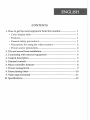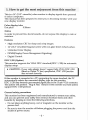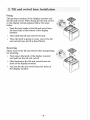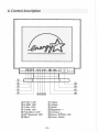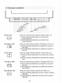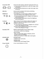
1
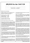
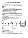
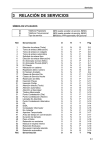
©cPTo Wiew UL
14" Color Monitor
( 13.2" viewable )
•
•
USER'S GUIDE
BENUTZERHANDBUCH
U.S.A.
U.S. FEDERAL COMMUNICATIONS COMMISSION
RADIO FREQUENCY INTERFERENCE STATEMENT
INFORMATION TO THE USER
NOTE : This equipment has been tested and found to comply with the limits for
a Class В digital device pursuant to Part 15 of the FCC Rules.
These limits are designed to provide reasonable protection against harmful
interference in a residential installation.
This equipment generates, uses, and can radiate radio frequency energy and, if
not installed and used in accordance with the instructions, may cause harmful
interference to radio communications.
However, there is no guarantee that interference will not occur in a particular
installation. If this equipment does cause harmful interference to radio or
television reception, which can be determined by turning the equipment off and
on, the user is encouraged to try to correct the interference by one or more of the
following measures:
• Reorient or relocate the receiving antenna.
• Increase the separation between the equipment and receiver.
• Connect the equipment into an outlet of a circuit different from that to which
the receiver is connected.
• Consult the dealer or an experienced radio/TV technician for assistance.
Changes or modification not expressly approved by the party responsible for
compliance could void the user's authority to operate the equipment.
Connecting of peripherals requires the use of grounded shielded signal cables.
Standards and Recommendations
Safety and Radio Interference Approvals
This product is designed in conformity with the following standards or other
normative documents :
Safety : EN 60950 / 1992 + Al, A2, A3
EMC : EN 55022 / 1994, EN 50082-1 / 1992
IEC 801-2 / 1991, IEC 801-3 / 1984, IEC 801-4 / 1988
to satisfy the basic requirements of Safety and EMC required by following
Directives:
• EMC Directive 89/336/EEC
• Low Voltage Directive 73/23/EEC & 93/68/EEC
Conformity with the above basic requirements is certified by means of the
CE marking on the product
Manufacturer's Disclaimer
All responsibility is declined :
• If the product is stored, transported, installed, modified, or used in a way
that is different from that described in the documentation.
a If the product is used in conditions different from those described in the
documentation.
• If any repair is carried out by unauthorized personnel.
• For any damage caused by normal wear and tear, uncontrollable events
and/or connection to devices that are not original.
The manufacturer reserves the right to carry out modifications to the product
described in this documentation at any time and without notice.
ENGLISH
CONTENTS
1. H o w to get the most enjoyment from this monitor
1
• Color display tube
1
• Features
1
• General safety precautions
1
• Precautions for using the video monitor
2
• Power source precautions
2
2. Tilt and swivel base installation
3
3. Connecting with external equipment
4
4. Control description
5
5. External controls
6
6. Micro-controller features
8
7. Power management
9
8. Preset timing chart
10
9. Video input terminal
11
10. Specifications
12
1. How to get the most enjoyment from this monitor
This is a 14" (13.2" viewable) color monitor to display signals from personal
or micro computers.
This manual has been prepared to assist you in becoming familiar with your
new display monitor.
Color display tube
Dot pitch
0.28mm
Notice
In order to prevent fire, shock hazards, do not expose this display to rain or
moisture.
Features
• High resolution CRT for sharp and crisp images.
• 14" (13.2" viewable) Diagonal screen with non-glare direct etched surface.
• Unlimited Color Display.
• DPMS(Display Power Management Signaling).
• Digital Control.
DDC 1/2B (Option)
This monitor supports the VESA DDC standard(DDC 1 / 2B) for automatic
display setup.
и CAUTION: If your video adaptor doesn't support fully VESA DDC 1/2B
(based on Philips IС bus) specification, DDC 1/2B function
does not work correctly.
If this monitor is connected to a PC supporting the same standard, the PC
automatically selects the connected display type for this monitor.
DDC 1/2B uses formerly unconnected signal pins in the 15-pin VGA connector.
The system will perform "Plug & Play" feature if both monitor and host system
support DDC 1/2B protocol.
General safety precautions
This monitor has been engineered and manufactured to assure your safety,
and you can prevent your safety from serious electrical shock and other
hazards by keeping in mind the following attentions.
• Do not place anything heavy, wet or magnetic on the monitor or the
power cord.
• Be sure to turn the monitor off before plugging the power cord into the
socket of power source.
-1-
• Make sure that the power cord and the other cords are securely and
rightly connected.
• Avoid operating the monitor in the place extremely heated, humid or.
affected by dust.
• Never cover the ventilation openings with any material and never touch
them with metallic or inflammable materials.
• Overloaded AC outlets and extention cords are dangerous. So are frayed
power cords and broken plugs. They may result in a shock or fire hazard.
Call your service technician for replacement.
• Do not open monitor. There are no user serviceable components inside.
There is dangerous high voltages inside, even when the power is off.
Contact your dealer if the monitor is not operating properly.
• Do not use an aerosol directly on the picture tube because overspray may
cause electrical shock.
Precautions for using the video monitor
As with any electrical equipment, careless use and unprofessional
maintenance are able to cause serious electrical shock and other hazards.
In the interests of safety, the following suggestions should be followed at all
time.
This monitor includes an appropriated plug for your area.
Power source precautions
Never remove the backcover of the monitor.
This will expose you to veiy high voltages and other hazards. If the display
monitor does not operate properly, remove the power cord from the wall
outlet, and contact your dealer. As a safety feature, this monitor is equipped
with a polarized, alternating current line plug. (Grounded,3 prong plug)
This plug wiU fit into the outlet only one way. If you are unable to insert the
plug fully into the outlet, or if the plug simply does not fit, contact an
electrician to replace the obsolete outlet.
Do not defeat the safety purpose of this polarized plug.
WARNING : When positioning this equipment, please ensure that the
main plug and the socket are easily accessible.
-2-
2. Tilt and swivel base installation
Fixing
This product consists of the display monitor and
the tilt and swivel. When fixing the tilt and swivel
to the display monitor,please follow the steps
below.
/
_
s
Push the four hooks of the tilt and swivel into
the four holes at the bottom of the display
monitor.
Then slide the tilt and swivel forward.
Then the latch is going to come above the tilt
and swivel base, and it is fixed firmly.
Removing
Please remove the tilt and swivel when transporting
for repairing.
• Push down the latch of the display monitor
and pull out the tilt and swivel.
• Slide backward the tilt and swivel from the
front of the display monitor.
• Pull out the tilt and swivel from the holes of
the display monitor.
-3-
/
„
•
>v
""ч
3. Connecting with external equipment
Cautions
Be sure to turn off the power of your computer before connecting the monitor.
-4-
4. Control description
® H-Size LED
©H-Shift LED
© V-Size LED
® V-Shift LED
©Pincushion LED
©-K®Trapezoid LED
©Select
® Adjust ® Adjust +
©RecaU
@ Brightness - +
© Contrast- +
©Power (DPMS) LED
©Power Switch
-5-
5. External controls
Е Э CCD C D ©
•
•
•
A RECALL
о о о о
СИ
•
SELECT
•
ffA
П ~ )
ТСА
СИР
©
Adjust • +
SELECT
PIN LED
POWER S/W
V-Position LED
P O W E R ( D P M S ) LED
Contrast
V-Size LED
Brightness
H-Position LED
H-Size LED
H-Size LED
0
H-Position LED
Ш
V-Size LED
Ш
RECALL
: Press the select button until the H-Size LED is on.
A) Press button[(+)direction] to increase the
horizontal size.
B) Press button[(-)direction] to decrease the
horizontal size.
: Press the select button until the H-Position LED is on.
A) Press button[(+)direction] to adjust the screen to
the right.
B) Press button[(-)direction] to adjust the screen to
the left.
: Press the select button until the V-Size LED is on.
A) Press button[(+)direction] to increase the vertical
size.
B) Press button[(-)direction] to decrease the vertical
size.
V-Position LED
: Press the select button until the V-Position LED is on.
A) Press button[(+)direction] to adjust the screen to
the top.
B) Press button[(-)direction] to adjust the screen to
the bottom.
Pincushion LED
: Press the select button until the Pin LED is on.
A) Press button[(+)direction] to bow out the vertical
side line.
B) Press button[(-)direction] to bow in the vertical
side line.
-6-
Press the select button until the Trapezoid LED is on.
A) Press button[(+)direction] to make the image wider
the bottom.
B) Press button[(-)direction] to make the image wider
at the top.
If you want to retrieve the factory presetting,
press the recall button.
The Brightness Control button adjusts the picture
mood according to the brightness of the room.
A) Press button[(+)direction] to heighten the brightness
level of the picture.
B) Press button[(-)direction] to lower the brightness
level of the picture.
The Contrast Control button adjusts the degree of
difference between the lightest and the darkest
sections on the screen.
A) Press button[(+)direction] to heighten the contrast
level of the displayed image.
B) Press button[(-)direction] to lower the contrast
level of the displayed image.
When control button is set to min or max.
The function LED( и ) is blinking
Out of range
When an unsuitable signal is detected, all the
function LEDs are blinking.
Check your system or setup video mode again.
Normal mode
POWER LED is lit Green
DPMS mode
POWER LED is lit Orange/Green
Use to turn Monitor on or off.
6. Microcontroller features
The microcontroller automatically detects the video board installed in user
system. When user turn on the monitor, the microcontroller first checks the
display mode memory stored in the user setting area and the factory
presetting area.
Display modes memory
The microcontroller has the memory capacity to store 17 different display
modes including timing formats and display settings.This memory capacity
is divided into two parts. One is the user setting area, the other is the factory
presetting area.
• User setting area
The user setting area maintains the recent 10 display modes
set by the user in its memory. The user can add nonstandard modes.
If users adjust display image, the image is saved
automatically.
Then the microcontroller always detects and displays the
last mode stored in the user setting area when the monitor
is turned on.
Note
If the timing input from the video card is not a factory preset
mode, the screen may not be correctly displayed.
Please adjust external controls to get the correct screen.
• Factory presetting area
There are 7 display modes stored in this area. These display
modes are preset at the factory and include most of the
display modes currently available (see TIMING CHART of
this manual).
User can also retrieve the factory preset mode by pressing
the RECALL button.
• Automatic save
The monitor automatically saves the new setting after 1
second inactivity.
-8-
7. Power management
This monitor is equipped with DPMS(Display Power Management Signaling)
function which automatically leads the monitor to the state of power saving
that consumes just a little power less than 8W, when the computer is left
unattended.
Although the monitor can be left in power-saving mode for longer periods,
we recommend that users turn it off after your daily work, because
degaussing helps maintain faultless color purity.
Operation
The DPMS function requires support from the computer system or any
software DPMS function applied, currently being used. If the keyboarder
mouse) is left unattended for a certain period, the program or system will set
the sync signals to DPMS modes. The DPMS function has three states. The
recommended signals, power consumption and recovery times are shown in
the table below.
STATES
NORMAL
SIGNAL
VS
VIDEO
Pulses
Pulses
ACTIVE
70W (Typical)
Pulses
BLANK
50W
STAND-BY No Pulse
SUSPEND
OFF
POWER
REC'OVFRY
LED INDICATOR
CONSUMPTION
ПМЕ
H.S
-
GREEN
WITHIN ORANGE/GREEN
1 SEC
Blink about 2 sec
No Pulse BLANK
LESS THAN
20W
WITHIN
3 SEC
ORANGE/GREEN
Blink about 1 sec
No Pulse No Pulse BLANK
LESS THAN
8 W
WITHIN
15 SEC
ORANGE
Pulses
<зт Note
When the monitor's signal cable is disconnected, the raster becomes visible.
This is not a malfunction. The screen will normalize when the signal cable is
connected again.
Ш Power consumption condition (Typical)
Input Voltage : 220VAC
Input Frequency: 50Hz/60Hz
Display Pattern : cross hatch
Display Size : 255 mm (H) X 190 mm (V)
-9-
8. Preset timing chart
Supported Video timings
This monitor shall be capable of displaying following video timing charts.
Timing charts
Border(T6)
ACTIVE(T4)
Bofdef(T6)
VIDEO
SYNC
FRONT PORCH(T5)
BACK P0RCH(T3)
PERIODfTI)
SYNC WIDTH (T2)
Timing table
L 0 W
^
. ^
^
HIGH LEVEL: 2.4V min
Horizontal
Frequency
Period (Г1)
Sync Width (T2)
Back Porch <T3)
Data Area (T4)
Front Porch (T5)
Dot
kHz
us
us
us
us
us
640
31.469
31.778
3.813
1.907
25.422
0.636
720
31.469
31.778
3.813
1.907
25.422
0.636
1024
35.524
28.151
3.920
1.250
22.800
0.180
640
37.500
26.667
2.032
3.810
20.317
0.508
800
37.879
26.400
3.200
2.200
20.000
1.000
800
46.875
21.333
1.616
3.232
16.162
0.323
1024
48.363
20.677
2.092
2.462
15.754
0.369
Border (T6)
Vertical
Frequency
Period (Tl)
Sync Width (T2)
Back Porch (T3)
Data Area fl'4)
Front Porch (75)
Border (T6)
Dot Rate
Interlaced
us
Line
Hz
ms
ms
ms
ms
ms
ms
MHz
Y/N
H
V
0
480
59.950
16.683
0.064
1.048
15.253
0.318
0
25.175
N
0
400
70.080
14.269
0.064
1.080
12.711
0.413
0
28.322
N
0
768
87.000
11.500
0.113
0.563
10.810
0.014
0
44.900
Y
0
480
75.000
13.333
0.080
0.427
12.800
0.027
0
31.500
N
0
600
60.317
16.579
0.106
0.607
15.840
0.026
0
40.000
N
0
600
75.000
13.333
0.064
0.448
12.800
0.021
0
49.500
N
0
768
60.004
16.666
0.124
0.600
15.880
0.062
0
65.000
N
-
-
+
-
+
+
-
-
+
+
-
+
+
-
Sync Polar
Notice
In order to attain the maximum resolution, it is necessary to equip the video card
compatible with that resolution in your PC.
-10-
9. Video input terminal
A 15 pin D-sub connector is used as the input signal connector.
Pin a n d input signals are shown in the table below.
Pin description
SIGNAL
SEPERATB
SYNC
DOC 1/2B (Option)
1
RED
RED
2
GREEN
GREEN
3
BLUE
BLUE
4
N.C
N.C
5
N.C
GROUND
6
RED GROUND
RED GROUND
7
GREEN GROUND
GREEN GROUND
8
BLUE GROUND
BLUE GROUND
9
N.C
N.C
10
LOGIC GROUND
LOGIC GROUND
11
GROUND
GROUND
12
N.C
SDA
13
H-SYNC
H-SYNC(TTL)
14
V-SYNC
V-SYNC(V CLK)
15
N.C
SCL
PIN
D-Sub miniature connector
102030405
Q \ \o 6 0 7 0 8 0 9 0 Ю / / Q
' \ 11012 • 13 014 015 • I
1020304050
Q\\0 6О7О8@9О10|/Л
\ 11 О 12 О 13 014 О 15 О /
-11-
10. Specifications
SIZE
CRT
Dot Pitch
Input
0.28 mm
Type
Non-Glare, VLMF Type
Signal
R.G.B Analog
Connector
15 pin D-Type
SYNC
H-F
30—50 kHz(Automatic)
V-F
50—130 Hz(Automatic)
Area(H x V)
Color
Display
14" (13.2" viewable)
Resolution
255 X 190mm (Max. Over Scan)
Max 1024 X 768(48kHz/60Hz)
User Controls
Power Management
Power Switch,Brightness,Contrast,H/V Size,
H/V Position, Recall, Pincushion, Trapezoid
As per VESA Standard, Lower than EPA's
recommendation
Compatibility
VESA, 8514/A, XGA, EVGA
DDC (Option)
VESA DDC 1/2B
Power Source
100 - 240 VAC(Universal Power) 1.3A 70W (Typical)
Safety &
Regulation
Temperature
Humidity
EMC
FCC, M P R I I , CE
Safety
UL, CSA, TUV-GS, ISO-9241-3, DHHS,
NEMKO, DEMKO, FIMKO, SEMKO, PCBC
Operating
Storage
Operating
Storage
5 to 35 degree Celsius
-30 to 60 degree Celsius
35 % to 80 % (Non-condensing)
30 % to 85 %
Acoustic Noise
Less than 70dB
Weight
Unit
: 10.5Kg
Carton : 12.5Kg
Dirnension(VV x H x Dmm)
352 x 360.2 x 372.5 mm
и Specification is subject to change without notice for performance improvement.
-12-