1
0
.,...
...-~--"'*·J
..,.
••
0
...
_
•
The recording requirements of many people have not developed beyond the elementary stages of making the
recording, rewinding the tape and then listening to the recorded programme, but others are far from satisfied
with such a procedure and the ability to hear the recording as it is made is an essential facility. This latter system
must, of course, employ an extra head and amplifier for Playback purposes thus adding to the cost of the machine
-an additional cost which is worth while in order to know immediately the quality of the recording.
•.
Brenell have found such machines to be in great demand so it is not surprising to find in their range of new
equipment a superb model giving such a facility-and in addition this model (MK 6 Type "M") has switching
provided to enable the recorded material to be immedi~tely compared with the programr:~e material being fed
to the recorder (a system known as A/B comparison) . In addition to facilities for record ' ;1g from microphone,
Radio, etc., special compensation circuits are incorporated in the recording amplifier to enable recordings to be
made directly from magnetic and ceramic gramophone pickups (normally one has to feed pickups via separate
pre-amps) and mixing facilities between microphone and pickup is possible by means of a cross-fade system (a
single control fades out one signal as it fades in the other).
Mod.ern transistors and techniques have enabled high powered amplifiers to be designed at a fraction of the
weight of their valved counterparts, it is not surprising therefore to find in this superb portable recorder, a power
output of 15 watts available. Wide range Bass & Treble control circuits are also incorporated. Whilst we think
principally of thi_s ma-c hine as 3 fa,pe recorder, it must be remembered that its amplifier may be used independently
of the recording facilities for reproduction of Radio, Gramophone and microphone signals in the home or hall
(Public Address).
The tape deck incorporated in the Brenell MK 6 "M" rL _order has 3 motors, 4 tape speeds, pausing mechanism,
digital revolution counter, end of tape (or tape breakage) stop and 3 heads of the highest quality. The low wow
and flutter content, wide frequency range and excellent s:gnai to noise ratios are all important factors which
make this machine so technically superior.
TRANSPORT SYSTEM (DECK)
3 outer rotor motors (Hysteresis Synchronous Capstan Drive for utmost speed Stability) .
Large Dynamically Balanced Flywheel (for minimising wow and flutter in the transport system).
4 Tape Speeds- 15, 7t, 3i and It i.p.s.
Reel sizes- up to Btin. (21 ems.) diameter.
Heads- 3 heads (Erase, Record, Replay), t track mono.
Tape Tension- Light fr iction brake (adjustable from top of deck , to ensure correct tension forcall reel sizes) .
Fast Rewind + Wind-on times - under 60 sees. for I 200ft. (360m .) tape.
Braking System - Positive, reliable system, self compensating with lining wear.
Pause Mechanism - Robust, simple to operate, lockable.
Position Indicator - 4 digit revolution counter. Push Button cancellation.
Wow and flutter measured on Gaumont Kalee wow and flutter me:t er.
15 i.p.s . less than 0.05%
7t "
" 0.08%
3! ,
.. Ct.Ol%
It ,
.. 0.12 %
End of tape or tape breakage auto-stop.
TAPE AMPLIFIERS
Separate record and replay amplifiers.
Record Amplifier .:Inputs for magnetic Pickup.
Ceramic Pickup.
Microphone (Sensitivity 100 microvolts- overload 55dB) .
{Optimum mic. impedance 200-'250 ohms).
Auxiliary Signals (Sensitivity 5 millivolts- impedance 250K ohms) .
f. Ul NAC..,
4 H V 47 /'( ,
(Radio- Hi Fi Pre-amps, etc.)
I
P. v ' c eJI.-' /6 0IIr
'Compensation for pickups selected by single push button.
rw
· ,_, -t
Mixin& of inputs- by pressing appropriate buttons, mic and pickup signals may be mixed for recordine and P.A. purposes.
Record Level Metering- A laree, edgewise scaled, illuminated ~ eter enables precise recording levels to .be maintained .
" Replay
Amplifier~:-
Power Output -
15 watts into 8 ohms @ 1% distortion .
8 watts into 15 ohms @ I% distortion.
Bass Control -IBdB to+ 18dB@ 50Hz ( c/s).
Treble Control -15dB to + 15dB @ 12KHz (Kc/s).
Output Sockets for Ext. Speaker (8 to 15 ohms) Type BS666.
Ext. Amplifier (220mV from fully modulated tape) BS666.
GENERAL
Frequency responses (Record/Replay) :15 i.p.s. (38cms.) 40Hz to 22KHz ±2dB.
7t i.p.s. ( 19cms.) 40Hz to 20KHz ±2dB.
3! i.p.s. (9.5cms.) 50Hz to 15KHz ±3dB.
1f i.p.s. ( 4.75cms.) 60Hz to 8KHz ±3d B.
Signal to noise ratio -56dB unweighted .
A/B Switching - Provision is made for "off the tape" monitoring and direct comparison of recording with the original signal.
The replay signal level may be independently controlled by the A/B balance control in order to obtain the correct replay level
at all speeds for critical comparison of recorded signal with the original.
Internal Speaker- A high quality speaker is fitted-this will be automatically disconnected when ext. speaker is used.
Amplifier Tape Speed Compensation - 4 push buttons are provided to enable the correct recording and replay compensation
circuits to be selected. These are deliberately not linked to the speed change switch so that individual requirements of operators
may be met.
·
STRAIGHT AMPLIFIER
By pressing the "A" button the preampl ifier circuits of the recording amplifier (prior to recording compensation circuits) are
coupled to the main amplifying circuits of the replay amplifier, thus there becomes available a versatile, powerful Hi-Fidelity amplifier
such as Q,ne would normally purchase as a separate unit. The Specifications under these conditions are as follows :Power Output- 15 watts into 8 ohms for 0.02 % distortion.
8 watts into 15 ohms for 0.02 % distortion .
Input sensitivities for above output levels :-
-+le ""/ t;.
( .,
(.)(...
' '72.
v i+
I z_ J?
' '-
Mic.
2 millivolts
Mag. P.up
3
47K ohms
Cer.
160
1.5 megohms
Radio
95
,
250K ohms
Bass Range@ 50Hz -18dB to + 18dB.
Treble Range@ 12KHz -15dB to + 15dB.
u k
Overall Frequency Response (with Bass and Treble controls to central (flat) position):
±2dB 20Hz (c/s) to 30KHz (Kc/s) .
Signal/Noise Ratio of Straight Amp. - Auxiliary position 78dB.
The recorder is designed for vertical or horizontal operation.
Size of Cabinet- 171in. X 16lin. X Sin .
Weight- 37 lbs . nett.
Brene/1 Engineering reserve the right to alter the specification as modifications are made.
Brenell Engineering· Co. Ljd.
231/235 ~tPool
oad, j:9"cttiil,'
. / Tel ,. o.: o~O'f 827;
(Q
f
I
I
BRENELL MARK 6 TYPE "M" AND MARK 610 TYPE "M''
TAPE RECORDERS
. Opera t ing Instructions
·'
THIS MACHINE IS FOR USE ON A.C. SUPPLIES ONLY
Mains Adjustment Plug
.
Befo1e connecting the recorder to the A.C. maim supply check that the mains
adjustment plug, situated in the circular recess at the rear of the cabinet, is
sel to the correct position, i.e.
·
240v for mains of 22'0v to 250v
21 Ov for mains of 200v to 220v
115v for mains of 100v to 125v
Mains Cable
This is a three cored cable stored in the pocket situated near the carrying
handle. To this cable a suitable 3 pin plug should be connected as follows:
Earth pin to Yellow/Green
Live pin to Brown
Neutral pin to Blue
L~cing the Tape
Fit the full reel oftape to the left hand spoolholder so that the tape feeds
from the left·hand side of the machine through the slot between the head
covers and via the adjustable tape guide to the empty reel which should be
fitted to the right hand spoolholder.
If correctly laced, the glossy side of the tape will be facing the operator and
the tape will lie between the heads and pressure pods and also between the
two pins near the left hand tape guide, i.e. in front of the auto stop pin which
movesin the slot but to the pad '5ide of the pin whic~ ,is attached to the erose
{L.H.) pressure pad arm.
Care ~ho\,Jid be taken to ensure that the tape does not become twisted when
attaching it to the empty reel. i.e. the coated side of the tape must face the
hub.
·
Spool R~taining Sc~
Screws are supplied for retaining the reels of tape on the spool holders. It is
advisable to fit these screws even though the machine may not be used in the
vertical position.
Adjustable Tape Guide (Mark 6 Type "M'i only)
The extreme right hand tape guide may be moved in the vertical plane in order
. to feed the Jape to the take-up reel without it touching the edges of the reel.
13-1
To adjust, hold lower milled edge and then turn upper edge in an anticlockwise (unscrewing) direction. You will then have twp sections
which may be relocked at the height necessary to feed the tape centrally
to the. take-up reel, by holding the lower section and screwing the upper
section hard against it.
Deck Switches
The two · large knobs control the Fast Wind, Fast Rewind, Record and
Replay functions of the tape deck whi 1st the small knob is used for the
selection of the tape speed.
Speed Changing
The switch provided has three positions but the tape speed wi II depend also
upon the size of capstan sleeve in use.
If the head covers are removed (Plr 'l Fit) one may observe the brass capstan
sleeve to the right of the tape heads.
The sleeve is a tight fit over the spindle and is retained in position by means
of a grub screw (see side of capstan sleeve).
Two sleeves are provided with each recorder normally the larger sleeve is
fitted and the smaller sleeve is stowed inthe pocket in the top of the cabinet.
When the larger sleeve is used the three speeds, 38cms (15 i . p.s.), 19 ems
(7! i .p .s .) and 9.5 ems (31 i. p .s.) may be selected by means of the speed
change switch (see switch positions marked 38, 19, 9 .5) whilst with the
· · smaller sleeve in use the speeds for each switch position wi II be halved (see
alternate markings 19, 9.5 and 4.75).
Note that the switch has but three positions and the knob cannot be turned
more than 60 degrees. Should a capstan sleeve be changed, ensure that
.
there is a clearance of approximately 1/16th inch between the bottom of the
sleeve and the top of the bearing which protrudes through the deck plate.
.
.
.
'·
Revolution Counter
~ <"
l •
I
A digital revolution counter is fitted - pressing the button to the right of the·
counter resets all digits .to zero.
Pause Control
. A lever to enable. the tape movement to be stopped. fvA.ove to extreme right
hand side to lock control. Do not use this control when winding or rewinding
the tape.
,lv\ains Supply Switch
The mains supply to both the Deck and Amplifier is switched by means of the
extreme right-hand button on the amplifier panel .
. This switch is of the push-push type, i.e. push for on or off.
It is suggested that after loading the machine with tape, the operator should
familiarise himself with the deck functions {not necessarily changing the
capstan sleeve at this juncture.).
13-2
Chctk fast wind, fast rewind, playback and record, noting that interlocking
prevents the large L.H. knob from being turned when the R ~H. knob is in
use and vice versa.
··
c
It is important to remember that tl--~ small block button to the left of the
Record/Replay. knob must be pressed before that knob con be turned to
. RECORD. This button will automatically return to the safety position when
the record replay knob is returned to the 'Stop 1 position.
Amplifier Controls, Sock_<:ts and Push Buttons
Push Buttons (from left to right)
(1)
P .U. Comp - This button enables the circuit characteristics for
Ceramic (button down) or Magnetic (button up) Gramophone Pick Up
cartridge to be selected. Action of switch is "Push-on Push-off 11 and no
other button or switch is released when this button is used.
{2)
P.U. - Press to bring Into circuit the sockets marked "CER P.U. 11
and "f.MG P.U." Note that only one of the sockets may be used at any
one time and the selected socket will be determined by the setting of
Button 1 (P~U. Comp.) These sockets ore for direct connection to a pickup
and not for outputs from Hi Fi amplifiers, etc.
(3)
Mic. - Press to bring_ into circuit the socke"t marked IIMIC II for use with
a microphone of 200- 600 ohms impedance.
4)
Rod ..;, . Press to bring into circuit the socket marked "Rod II for
recording from Radio receivers a•- :1 high level signals such as wi II be
obtained from Hi Fi amplifiers, etc.
NOTE:
Buttons - P .U. 1 Mic and Rod - When one is pressed the other
two will be released~ However, mixing of microphone and P.U. signals
may be ol' lained ifboth P.U. and Mic buttons are pressed. Under these
conditions the MIXER CONTROL is brought into circuit (see notes on
MIXING).
\
11
(5)
A" - When pressed, the signals fed into P.U., Mic and Rod will
be fed 'Straight Through' the amplifier and speaker. Used when amplifying
with or wi.thout recording and for comparison purposes when recording.
NOTE:
Amplification of Mic signals will cause a howling sound if Mic
and speaker are too close and the amplifier's volume control is advanced
too far.
8 11 - This button is interlatched with "A". When "B" is pressed
'A" wi II be released and signals from the tape wi II be passed to the
amplifier and speaker. .
·
6)
11
The level of playback signal may be adjusted by means of the "A/B Balance"
control. Alternate pressing of the A and B buttons whilst recording is taking
place will enable the operator t,.. make a critical comparison between the
recorded and ~ original signals; the A/B balance control should be used to
bring the playb?ck signal strength to that of the origiral.
13-3
These interlatched buttons enai.Jie the correct
8)
4.75
9.5
9)
19
to be selected. Press the button which
10)
38
corresponds with the tape speed selected.
7)
recording and replay amplifier characteristics
SO~KET EXT AMP.
Available at this socket is a signal for feeding to an external amplifier
(Hi Fi or Public Address) Signals from this so.cket wi II not be affected
by the Treble, Bass or Volume controls but the setting of the A/B
Balance control will affect the Replay level.
·
SOCKET EXT SPEAKER
For feeding signals to an extcr · al loudspeaker. The impedance of such
a speaker should be 8 ohms or rnore. Internal Speaker wi II be disconnected
when external speaker is plugged in.
BUTTON ON/OFF
Mains Switch. Push on/Push off for connecting and disconnecting mains
power. Power on is indicated by the illumination of the meter.
MIXER CONTROL
Used -for mixing of pick-up and microphone inputs. Operative only when
"P.U. 11 and "Mic" buttons are pressed down. See notes on "MIXING".
RECORD CONTROL
This control wi II be operative o .. ly when the deck is switched to Record.
Adjust levels as necessary to give a recording signal which at peak levels
causes the meter needle ·to rise to 0 dB (the beginning of the red position
of the scale.)
' ~
• ~ : . ~- j_.
A/B BALANCE CONTROL ·
Adjusts only signal level from playback head. The odjust~ent wi II only be·
apparent when button 11 B11 is pressed and the tape is in motion. See also
(6) above.
TREBLE CONTROL
-·
Affects the high freql.lency response of the signal in both "A 11 and "B"
operating modes. The H .F. characteristic of the signal being recorded is
not affected by this control •. The range of adjustment covers :.15 dB+ 15 dB at 12 KHZ.
BASS CONTROL
Affects the low frequency response of the signal in both "A" and "B"
operating modes • . The low frequency characteristics of the signal being
recorded is not affected by this control. The . range of adjustment covers
- 18 dB + 18 dB at 50 Hz.
.
13-4
VOLUME CONTROL
Adjusts the sound level from loudspeaker and is common to the signal from
the recorded tape ("8" button pressed) and the original signal being fed
straight through · the amp I ifier ("A" Button pressed}.
·
BOCORDING PRQCEDURE
. 1~
lace Tape on deck.
2.
Select tape speed (the faster the speed, the better the quality of
recording).
3.
.Reset Dig Hal counter (Press button to right of it).
4.
Switch on Mains Supply.
5.
Feed signols to be recorded into oppropriate input socket and press
the appropriate selector button.
6.
Press button "A" (To hear the programme you wish to record).
7.
Adjust Volume control for normal listening level.
NOTE: If recording is to be made from a m_icroph()ne do not
advance this volume control otherwise feedback between th.f!
microphone ·and loudspeaker will cause a howl to build up.
Headphones may be plugged into the ext. speaker socket if
microph9ne recordings are to be monitored.
B.
Adjust Treble and Bass Controls as desired.
9.
Press Button which corresp.,. ::1d_s to tape speed.
10.
Switch Deck to Record Position (small black button must be
pressed in order to permit this switching action).
Immediately operate Pause Control (lock by moving to to
right of slot).
.
\
.
~
Adjust Record level control until loudest signals cause meter
needle to rise to 0 dB. Note position of knob pointer then
turn control down to minimum position •
:: '
.;
'
f''l'·
.
~
.'
'.
12.
Release the Pause Control and advance the Recording level
control to the position noted to cause peak signals to raise the
needle to OdB. ·
13. . Press B button to enable the recorded signal to be
14.
hea~d.
Adjust A/B Balanc.e control to give a recorded level similar to
the original signal level heard when A button is pressed.
Alternate pressing of the A and B buttons whilst adjusting the
A/B Balance Control may be necessary . - the object being to
obtain a recording which is similar to the original sound.
In some circumstances the level of the original signal may be
too low or too great for c •. tical comparison purposes • .
A balancing of signals to the Radio input socket should be
possible with levels ranging from 50 mV to 300 mV. ·
13-5
With lower input level signals than 50 mY the recorded signal
from the tape wi II be greater than the original signal level even
though the
balance control is turned to miniQ'lum.
Conversely, higher levels of input signal than 300 mY wi II be
greater with the A button pressed than can be obtained from the
Tape with the A/B ba Ionce centro I set to maxi mum.
A/B
.•
MIXING
Signals fed into the microphone and pickup sockets may be mixed if
both Mic and PU buttons ore pressed (steady, equal pressure on both
buttons wi II cause them both to be latched down). When both buttons
are down, the mixer control will be brought into circuit and when fully
clockwise the microphone signals wi II be at maximum whi 1st turning
this control in the opp6site direction will raise the pickup signal to
maximum.
When either signal is at maximum, the other signal wi II be cut off. With
a little practice perfect fod!'2g in.ond out of these two signals and when
required the mixing of them will be achieved.
Neither signal should c~use the .eedle of the meter to enter the red
pOsition of the scale .. govern this level by means of the Record Level
Control.'
The use of headphones wi II be invaluable · in assessing the degree of
mixing (remember that the loudspeakef .should not be used whi 1st recording .
from a microphone). For speech with musical background to be clear
the musical background should he very low.
·
'·
ECHO EFFECTS
Whilst warning has been given that a loudspeaker should not be operative
whilst using a microphone because of the howl which may ariSe, very
careful use of the. loudspeaker output may be used to create on echo effect.
The "8 11 button must be pressed, the Record level control adjusted for normal
recording and when the echo is required very 'carefully advance the main
volume control so that the microphone receives this sound which, being a
fraction of a second after the original sound (due to. the spacing of the record
and replay heads) wi II be re-recorded as woo ld a reflected sound. The delay
time will dependon the tape speed so one may have delay times of 1/12; ·
1/6 and 2/3 of a second over the four speeds of 38, 19, 9.5 and 4. 75 ems.
(15, 7~, 3~ and 1 7/8 i.p.s.)
REPLAY OF PREVIOUSLY RECORDED TAPE
J.
2.
Sele~t the Tape d~ck speed.
· Press button which corresponds to tape speed.
3.
Press button ns II.
4.
Press mains switch button.
'·
13-6
".
5.
Switch Deck to Replay.
6.
Adjust Vol.ume, Treble and Bass controls as required.
7.
Remember that the A/8 Balance Control wi II alter the
replay level ~ · adjust as necessary.
.
WARNING: DO NOT SWITCH DECK TO RECORD OR ERASURE
WILL OCCUR.
GENERAL INFORMATION
The recorder may be operated in the horizontal or vertical position.
Should tape break or run out during recording or replaying the Take-up
motor (right hand) wi II automatically be switched off. The recorder
itself, however, will NOT be switched off; therefore, make a point
of ensuring that the deck's record/replay switch is turned to the "OFF"
position when the recorder is not in use. leavin·g the record/replay
switch in the "ON" position w H~ mains switched off could cause flats
to develop on the rubber tyred pinch and idler wheels.
The back tension on the feed motor (left ha~d) may be adjusted by
turning the small recessed screw situated between this motor and the
speed change switch • Turning the screw in a · clockwise direction wi II
INCREASE the back tension. A change of tension is normally only
required when small reels or reels with very small diameter hubs are used,·
such reels .will require a REDUCTION of tension i.e.- turn screw
ANTICLOCKWISE. The normal setting for the screw is: "with a full 7"
reel of tape on the l.h. spoolholder the back tension should be just
sufficient to prevent the tape unreeling jerkily whel'l passing the heads at
a selected tape speed." The effect of excessive pressure will be to cause
"WOW" towards the end of the reel.
Clean the tape oxide ,from the heads at frequent intervals. A strip of
·cloth damp"fmed w:th water, or one of the many cleansing fluid~ · available
. for cleaning tape heads, should be gently drawn to and fro across the
faces of the heads - each head being treated separately unti I all trace
of oxide is removed. The pinch wheel which presses the tape against the
capstan sleeve and the tape guides should be regularly cleaned with
dampened cloth (avoid using the cloth which will leave a deposit of fluff).
The meters wi II not oper~te unless the deck ~s switched to the record mode.
The tape movement may be immediately arrested if the pause control is .
. moved to the full extent of its movement.
If good quality r~cordirigs are to be made, it is essential that the tape be
fully and correctly, modulated as indicated by the meter readings rising to
OdB points on peak levels.
Fuses .
Two fuses are incorporated in this machine.
Mains Fuse A 2 amp cartridge fuse which is mounted within the mains adjustment
·
· plug •. For access remOve this plug (situated within the circular recess .
at the rear of the cabinet) and carefully prise off the plastic co.ver from
the plug.
D.C. Fuse A 1 .5 amp cartridge fuse (plus 1 spore) is mounted i'nternally. For access
.
· .remove the ·two domed screws from the sides of the cabinet (FRONT ONLY) so
.
that the unit may· be rais~ on its rear hinges.
The 1 .5 amp fuses are mounted within the power unit in the rear r.h. corner
of the cabinet.
Brenell Engineering Co. ltd. 231-2~5 Liverpool Rood, London Nl1LY.
Telephone: 01- 607 8271'.
1~-7
·B
...
-.,.,
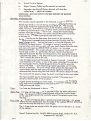
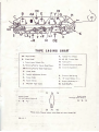
TAPE LACING CHART
.. .
..... .
1,.
A1. Tape Guides . .
K.
B.
Erase Head .
L1, L2, L3.
C.
Superimpose Release Pin.
M. Take-up Pon .
I
01. Retaining Post for clip·on Head Cover.
•. ' · I · .
Dl. Retaining Post for fi~ed Head Cover.
Rubber Fonch Wheel.
Pressure Pads .
N.
Pressure PJd
0.
Crescent-shaped lever .
S.
Pressure Pad Sprongs
oper;~tong
lever .
E.
Record Head.
F.
Azimuth adjus.tment Screws.
G.
Capstan Shaft.
T.
' N' lever
H.
Capstan Sleeve.
V.
Replay (PiaybJck) Ht .. "
J.
Adjustable Tape Guide .
W. Auto Stop Pin
Rclc;~se
S·:r
! ;;
.
'
('
; .;n
Speeds a•allable
woth sm~ll C'lpH~n fottcd to G
;. :' 7}
..
]1
1i
.
! .P·~
H
' ..
3f 7t
.'
., '
7t
15
Please note:-The ~opeed selector switch does not route throuch 360..
[lJ.
u- 7
Speeds a•adaboe
fitted to G
c~psun
'f ' .
'
31
C•t
3i
with larce
l
,. :
7;
15