1
GB
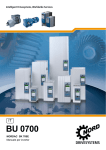
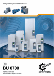
BU 0700
NORDAC SK 700E
Frequency inverter manual
NORDAC SK 700E Operating Manual
N O R D A C SK 700E frequency inverters
Safety and operating instructions
for drive power converters
(as per: Low Voltage Directive 2006/95/EEC )
1. General
During operation, drive power converters may, depending on their
protection class, have live, bare, moving or rotating parts or hot
surfaces.
Unauthorised removal of covers, improper use, incorrect installation
or operation causes a risk of serious personal injury or material
damage.
Further information can be found in this documentation.
All transportation, installation and initialisation and maintenance
work must be carried out by qualified personnel (comply with
IEC 364, CENELEC HD 384, DIN VDE 0100, IEC 664 and DIN VDE
0110, and national accident prevention regulations).
For the purposes of these basic safety instructions, qualified
personnel are persons who are familiar with the assembly,
installation, commissioning and operation of this product and who
have the relevant qualifications for their work.
2. Proper use in Europe
Drive power converters are components intended for installation in
electrical systems or machines.
When installed in machines, the drive power converter cannot be
commissioned (i.e. commencement of the proper use) until it has
been ensured that the machine meets the provisions of the EC
Directive 2006/42/EEC (Machine Directive); EN 60204 must also be
complied with.
Commissioning (i.e. implementation of the proper use) is only
permitted when the EMC directive (2004/108/EEC) is complied with.
Drive power converters with a CE label meet the requirements of the
Low Voltage Directive 2006/95/EEC. The harmonised standards for
drive power converters stated in the declaration of conformity are
used.
Technical data and information for connection conditions can be
found on the rating plate and in the documentation, and must be
complied with.
The drive power converters may only be used for safety functions
which are described and explicitly approved.
3. Transport, storage
Information regarding transport, storage and correct handling must
be complied with.
4. Installation
The drive power converter must be protected against
impermissible loads. Especially during transport and
handling, components must not be deformed and/or
insulation distances must not be changed. Touching of
electronic components and contacts must be avoided.
Drive power converters have electrostatically sensitive
components, which can be easily damaged by incorrect
handling. Electrical components must not be mechanically
damaged or destroyed (this may cause a health hazard!).
5. Electrical connection
When working on live drive power converters, the applicable
national accident prevention regulations must be complied
with (e.g. BGV A3, formerly VBG 4).
The electrical installation must be implemented as per the
applicable regulations (e.g. cable cross-section, fuses, earth
lead connections). Further instructions can be found in the
documentation.
Information regarding EMC-compliant installation – such as
shielding, earthing, location of filters and installation of
cables – can be found in the drive power converter
documentation. These instructions must be complied with
even with CE marked drive power converters. Compliance
with the limit values specified in the EMC regulations is the
responsibility of the manufacturer of the system or machine.
6. Operation
Systems where drive power converters are installed must
be equipped, where necessary, with additional monitoring
and protective equipment as per the applicable safety
requirements, e.g. legislation concerning technical
equipment, accident prevention regulations, etc.
The parameterisation and configuration of the drive power
converter must be selected so that no hazards can occur.
All covers must be kept closed during operation.
7. Maintenance and repairs
After the drive power converter is disconnected from the
power supply, live equipment components and power
connections should not be touched immediately, because of
possible charged capacitors. Observe the applicable
information signs located on the drive power converter.
Further information can be found in this documentation.
The installation and cooling of the equipment must be implemented
according to the regulations in the corresponding documentation.
These safety instructions must be kept in a safe place!
2
BU 0700 GB-1411
Table of contents
3.4 Customer I/Os terminals ......................................... 56
1 GENERAL INFORMATION .............................................. 4
3.5 Colour and contact assignments for the encoder ... 57
1.1 Overview...................................................................4
4 COMMISSIONING ........................................................... 58
1.2 Delivery.....................................................................5
4.1 Basic settings ......................................................... 58
1.3 Scope of supply ........................................................ 5
4.2 Basic operation - Quick start guide ......................... 59
1.4 Safety and installation information ............................ 6
4.3 Minimum configuration of control connections ........ 60
1.5 Certifications ............................................................. 7
1.5.1 European EMC guideline .....................................7
1.5.2 UL and cUL certification ....................................... 7
5 PARAMETERISATION .................................................... 61
2 ASSEMBLY AND INSTALLATION .................................. 8
2.1 Installation ................................................................ 8
2.2 Dimensions of the frequency inverter ....................... 9
2.3 UB line filter up to 22kW (accessory) ...................... 10
2.4 Chassis line filter (accessory) ................................. 11
2.5 Line choke (accessories) ........................................ 12
2.6 Output choke (accessories) .................................... 13
2.7 UB brake resistors (accessory) ............................... 14
2.7.1 Electrical data UB BR ........................................ 14
2.7.2 Dimensions UB BR ............................................ 14
2.8 Chassis brake resistors (accessory) ....................... 15
2.8.1 Electrical data Chassis BR ................................. 15
2.8.2 Dimensions Chassis BR .................................... 15
2.9 Wiring guidelines .................................................... 16
2.10 Electrical connections ........................................... 17
2.10.1 Line and motor connections ............................. 17
2.10.2 Mains connection up to 22kW (PE/L1/L2/L3) ... 18
2.10.3 Mains connection from 30kW (PE/L1/L2/L3) .... 18
2.10.4 Motor cable (U/V/W/PE) ................................... 19
2.10.5 Brake chopper connection up to 22kW (+B/-B) . 19
2.10.6 Brake resistor connection from 30kW (BR+ZW) 19
2.10.7 Control unit connection .................................... 20
5.1 Parameter description ............................................ 63
5.1.1 Operating displays ............................................. 63
5.1.2 Basic parameters ............................................... 64
5.1.3 Motor data / characteristic curve parameters ..... 69
5.1.4 Control parameters ............................................ 73
5.1.5 Control terminals................................................ 76
5.1.6 Extra functions ................................................... 88
5.1.7 Positioning ......................................................... 98
5.1.8 Information ......................................................... 98
5.2 Parameter overview, User settings ....................... 103
6 ERROR MESSAGES ..................................................... 109
6.1 ControlBox displays (option) ................................. 109
6.2 ParameterBox displays (option) ........................... 109
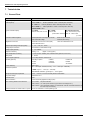
7 TECHNICAL DATA ........................................................ 114
7.1 General Data ........................................................ 114
7.2 Continuous thermal output ................................... 115
7.3 Electrical data ....................................................... 115
7.4 Electrical data for UL/cUL certification .................. 117
8 ADDITIONAL INFORMATION ...................................... 118
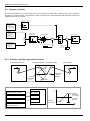
8.1 Setpoint processing in the SK 700E ..................... 118
8.2 Process controller ................................................. 120
8.2.1 Process controller application example ........... 120
8.2.2 Process controller parameter settings ............. 121
3 OPERATION AND DISPLAY .......................................... 21
8.3 Electromagnetic compatibility (EMC) .................... 122
3.1 Technology unit ...................................................... 22
3.1.1 ParameterBox .................................................... 23
3.1.2 ControlBox ......................................................... 33
3.1.3 PotentiometerBox .............................................. 37
3.1.4 RS 232 Box (SK TU1-RS2) ................................ 38
3.1.5 CANbus module (SK TU1-CAN) ........................ 38
3.1.6 Profibus module (SK TU1-PBR)......................... 38
3.1.7 Profibus 24V module (SK TU1-PBR-24V).......... 39
3.1.8 CANopen module (SK TU1-CAO) ...................... 39
3.1.9 DeviceNet module (SK TU1-DEV) ..................... 39
3.1.10 InterBus module (SK TU1-IBS) ........................ 40
3.1.11 AS interface (SK TU1-AS1) ............................. 40
8.4 EMC limit value classes........................................ 122
8.5 EMC limit value classes........................................ 124
8.6 Maintenance and servicing information ................ 125
8.6.1 Maintenance notes .......................................... 125
8.6.2 Repair notes .................................................... 126
8.7 Additional information ........................................... 126
8.8 RS 232 PC interface on RJ12 socket ................... 127
8.8.1 SK 700E up to 22kW ....................................... 128
8.8.2 SK 700E from 30kW ........................................ 128
9 KEYWORD INDEX......................................................... 129
3.2 Customer units ....................................................... 41
3.2.1 Basic I/O ............................................................ 45
3.2.2 Standard I/O ...................................................... 46
3.2.3 Multi I/O ............................................................. 47
3.2.4 Multi I/O 20mA ................................................... 48
3.2.5 BUS customer units ........................................... 49
3.3 Special extension units ........................................... 50
3.3.1 PosiCon I/O ....................................................... 54
3.3.2 Encoder I/O........................................................ 55
BU 0700 GB-1411
3
NORDAC SK 700E Operating Manual
1
General information
The series NORDAC SK 700E is the follow-on development of the proven vector series. These devices are characterised by
the high modularity and excellent control characteristics.
These devices are provided with non-sensor vector current control system which constantly ensures an optimised voltage-tofrequency ratio in combination with a motor model of an three-phase asynchronous motor. This has the following significance
for the drive: Peak start-up and overload torques at constant speed.
Due to its modular construction, the variously combinable technology units, customer units and special extension units, this
device series is suitable for all possible applications.
Devices for constant load:
Due to the numerous setting options, these inverters are capable of controlling all three-phase motors. The performance range
goes from 1.5kW to 22kW (3~ 380V...480V) with an integrated line filter and from 30kW to 132kW (3~ 380V...480V) with
optional external line filter. The overload capacity of these devices is 200% for 3.5 seconds and 150% for 60 seconds.
Device for quadratically increasing loads SK 700E-163-340-O-VT:
In the performance range 160kW (3~ 380V...480V) a variant for quadratically increasing load is available. This load profile is
typical for fans and various pump applications. In contrast to the devices used for constant load torque, the overload capacity
here is limited to 125%.
NOTE:
The SK 700E with the performance range 30kW to 160kW varies in some technical details from the lower
performance devices. Details can be found in this manual.
This manual is based on the device software V3.4 Rev4 (P707) for the SK 700E. If the frequency inverter used has a different
version, this may lead to some differences. If necessary, you can download the current manual from the Internet
(http://www.nord.com/)
The most important amendments in comparison with edition 3910 are the correction of errors and amendments associated with
UL certification.
1.1 Overview
Properties of the basic device:
Heavy starting torque and precise motor speed control setting with sensorless current/vector control.
Can be mounted next to each other without additional spacing
Permissible environmental temperature range: 0 to 50°C (please refer to technical data)
Integrated line filter for limit curve A as per EN 55011 (up to and including 22kW)
Automatic measurement of the stator resistance
Programmable direct current braking
Integrated brake chopper for 4 quadrant drive
Four separate online switchable parameter sets
The characteristics of the basic equipment with an additional technology unit, customer unit or special extension unit are
described in Chapter 3, 'Operation and displays'.
4
Subject to technical alterations
BU 0700 GB-1411
1. Allgemeines
1.2 Delivery
Check the equipment immediately after delivery/unpacking for transport damage such as deformation or loose parts.
If there is any damage, contact the carrier immediately and implement a thorough assessment.
Important! This also applies even if the packaging is undamaged.
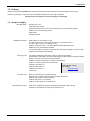
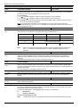
1.3 Scope of supply
Standard design:
Available accessories:
Mounting unit IP 20
Integrated brake chopper
Integrated line filter for limit curve A as per EN 55011 (up to and including 22kW)
Blanking cover for technology unit slot
Shield angle
Operating manual
Brake resistor, IP 20 (Chapter 2.7/2.8)
Line filter for limit curve A or B as per EN 55011, IP 20 (Chapter 2.3/2.4)
Line and output choke, IP 00 (Chapter 2.5/2.6)
Interface converter RS 232 RS 485 (supplemental description BU 0010)
NORD CON, PC parameterising software
p-box (ParameterBox), external control panel with LCD plain text display, connection cable
(supplemental description BU 0040 DE)
Technology unit:
Customer units:
Special extension units:
BU 0700 GB-1411
ControlBox, detachable control panel, 4-figure 7-segment LED display
ParameterBox, detachable control panel with background illuminated LCD plain text display
RS 232, accessory component for RS 232 interface
CANbus, accessory component for CANbus communication
Profibus, accessory component for Profibus DP
CANopen, Bus switch-on
Additional BUS manuals
DeviceNet, Bus switch-on
are available..
InterBus, Bus switch-on
> www.nord.com <
AS interface
Basic I/O, limited scope for signal processing
Standard I/O, moderate scope for signal processing and RS 485
Multi I/O, high scope for signal processing
CAN I/O, Bus switch-on via CANbus
Profibus I/O, Bus switch-on via Profibus DP
PosiCon I/O, positioning component (supplemental description BU 0710 DE)
Encoder I/O, incremental encoder input for speed control
Subject to technical alterations
5
NORDAC SK 700E Operating Manual
1.4 Safety and installation information
NORDAC SK 700E frequency inverters are equipment for use in industrial high voltage systems and are operated at voltages
that could lead to severe injuries or death if they are touched.
Installation and other work may only be carried out by qualified electricians and when the device is
disconnected. The manual must always be available for these persons and must be complied with.
Local regulations for the installation of electrical equipment as well as for accident prevention must be
complied with.
The equipment continues to carry hazardous voltages for up to 5 minutes after being switched off at the
mains. The equipment may only be opened or the cover or control element removed 5 minutes after the
equipment has been disconnected from the power supply. All covers must be put back in place before the line
voltage is switched back on again.
Even during motor standstill (e.g. caused by a release block, blocked drive or output terminal short circuit), the
line connection terminals, motor terminals and braking resistor terminals may still conduct hazardous voltages.
A motor standstill is not identical to galvanic isolation from the mains.
Attention, even parts of the control card and, in particular, the connection plug for the removable technology
units can conduct hazardous voltages. The control terminals are mains voltage free.
Warning, under certain settings the frequency inverter can start automatically after the mains are switched on.
The circuit boards contain highly-sensitive MOS semiconductor components that are particularly sensitive to
static electricity. Avoid touching circuit tracks and components with the hand or metallic objects. Only the
terminal strip screws may be touched with insulated screwdrivers when connecting the cables.
The frequency inverter is only intended for permanent connection and may not be operated without effective
earthing connections that comply with local regulations for large leak currents (> 3.5mA). VDE 0160 requires
2
the installation of a second earthing conductor or an earthing conductor cross-section of at least 10 mm .
Normal FI-circuit breakers are not suitable as the sole protection in three-phase frequency inverters when
local regulations do not permit a possible DC proportion in the fault current. The standard FI circuit breaker
must comply with the new design as per VDE 0664.
The inverter must be mounted in a switch cabinet that is suitable for its immediate surroundings. In particular it
must be protected from excess humidity, corrosive gases and dirt.
In normal use, NORDAC SK 700E frequency inverters are maintenance free. The cooling surfaces must be
regularly cleaned with compressed air if the ambient air is dusty.
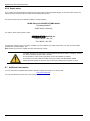
ATTENTION! DANGER TO LIFE!
The power unit can continue to carry voltages for up to 5 minutes after being switched off at the mains.
Inverter terminals, motor cables and motor terminals may carry voltage!
Touching open or free terminals, cables and equipment components can lead to severe injury or death!
6
Subject to technical alterations
BU 0700 GB-1411
1. Allgemeines
CAUTION
Children and the general public must be kept away from the equipment!
The equipment may only be used for the purpose intended by the manufacturer. Unpermitted
modifications and the use of spare parts and additional equipment that has not be bought from or
recommended by the equipment manufacturer can lead to fire, electric shock and injury.
Keep these operating instructions in an accessible location and ensure that every operator uses it!
Warning:
This product is covered under marketing classification IEC 61800-3. In a domestic environment, this product can
cause high frequency interference, which may require the user to take appropriate measures.
An appropriate measure would be the inclusion of a recommended line filter.
1.5 Certifications
1.5.1 European EMC guideline
If the NORDAC SK 700E is installed according to the recommendations in this instruction manual, it
meets all EMC directive requirements, as per the EMC product standard for motor-operated systems
EN 61800-3.
(See also Chapter 8.3 Electromagnetic compatibility [EMC].)
1.5.2 UL and cUL certification
(Used in North America)
“Suitable for use on a circuit capable of delivering not more than 5000 rms symmetrical
amperes, 380…480 Volts (three phase)” and “when protected by 600V J class fuses”
(Frequency inverter size 1 … 4), resp. „when protected by 600V R class fuses or faster”
(Frequency inverter size 5 … 7) as described in Chapter 7.4."
Suitable for use on a circuit capable of delivering not more than 5000A (symmetrical),
380...460 Volts (three phase) and when protected by "600V J class fuses" (Size 1 ...4
frequency inverters) or a "600V R class fuse or faster" (Size 5 ... 7 frequency inverters) as described in Chap. 7.4.
NORDAC SK 700E frequency inverters have motor overload protection.
Further technical details can be found in Section 7.4.
Not incorporated Overspeed Protection.
Relays on extension units and customer interface units may only be used at 230V ac maximum, same phase only.
Maximum Surrounding Air Temperature 40°C.
Torque Value for field wiring terminals:
o Models SK700E-151-340-A up to SK700E-751-340-A (mains circuit, motor, braking resistor): 4.4 … 5.3 lb-in (0.5 … 0.6 Nm)
o Models SK700E-112-340-A up to SK700E-152-340-A (mains circuit, motor, braking resistor): 11 … 13.27 lb-in (1.2 … 1.5 Nm)
o Models SK700E-182-340-A up to SK700E-222-340-A (mains circuit, motor, braking resistor): 21.2 … 35.4 lb-in (2.4 … 4.0 Nm)
o Models SK700E-302-340-A up to SK700E-372-340-A
Mains circuit: 53.1 … 70.8 lb-in (6 … 8Nm)
motor and braking resistor: 28.32 … 32.74 lb-in (3.2 … 3.7 Nm)
o Models SK700E-452-340-A up to SK700E-552-340-A
Mains circuit and motor: 53.1 … 70.8 lb-in (6 … 8 Nm)
braking resistor: 28.32 … 32.74 lb-in (3.2 … 3.7Nm)
o Models SK700E-752-340-A up to SK700E-902-340-A
Mains circuit and motor: 132.7 … 177 lb-in (15 … 20Nm)
braking resistor: 53.1 … 70.8 lb-in (6 … 8Nm)
BU 0700 GB-1411
Subject to technical alterations
7
NORDAC SK 700E Operating Manual
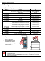
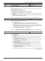
2
Assembly and installation
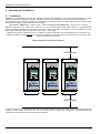
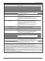
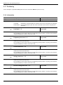
2.1 Installation
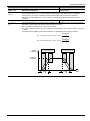
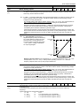
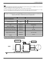
NORDAC SK 700E frequency inverters are available in various sizes depending on the output. When installed in a control
cabinet, the size, power dissipation and perm. ambient temperature must be taken into account to prevent device failures.
The equipment requires sufficient ventilation to protect against overheating. Reference values apply here for the spaces above
and below the frequency inverter within the control cabinet.
(up to and inc. 22kW, above > 100mm, below > 100mm and from and inc. 30kW above > 200mm, below > 200mm)
Electrical components (e.g. cable ducts, contactors, etc.) can be located within these limits. There is a height-dependent
minimum separation distance from the frequency inverter for these components. This distance must be a minimum 2/3 of the
object height. (Example: cable duct 60mm high 2/3 60mm = 40mm gap)
Additional side gaps for devices up to and inc. 55kW are not required. Mounting can be immediately next to each other. The
installation position is normally vertical. It must be ensured that the cooling ribs on the rear of the device are covered with a flat
surface to provide good convection.
Warm air must be vented above the device!
>100/200 mm
R
R
R
R
vector
vector
R
R
vector
N O RD A C
N O RD A C
N O RD A C
700E
700E
700E
>100/200 mm
If several inverters are arranged above each other, ensure that the upper air entry temperature limit is not exceeded. (See also
Chapter 7, Technical data). If this is the case, it is recommended that an "obstacle" (e.g. a cable duct) is mounted between the
inverters so that the direct air flow (rising warm air) is impeded.
8
Subject to technical alterations
BU 0700 GB-1411
2 Assembly and installation
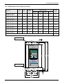
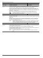
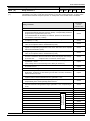
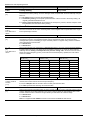
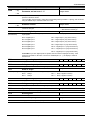
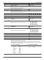
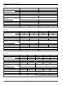
2.2 Dimensions of the frequency inverter
Length
Width
L1
B1
SK 700E-151-340-A …
SK 700E-401-340-A
281
SK 700E-551-340-A
SK 700E-751-340-A
Device type
Installation
depth
Detail: mounting
Weight
T
Length L2
Width B2
Length L3
approx.
123
219
269
100
223
5.5
4 kg
331
123
219
319
100
273
5.5
5 kg
SK 700E-112-340-A
SK 700E-152-340-A
386
167
255
373
140
315
5.5
9 kg
SK 700E-182-340-A
SK 700E-222-340-A
431
201
268
418
172
354
6.5
12.5 kg
SK 700E-302-340-O
SK 700E-372-340-O
599
263
263
582
210
556
6.5
24kg
SK 700E-452-340-O
SK 700E-552-340-O
599
263
263
582
210
556
6.5
28kg
SK 700E-752-340-O …
SK 700E-902-340-O
736
263
336
719
210
693
6.5
45kg
SK 700E-113-340-O ...
SK 700E-163-340-O
1207
354
263
1190
142 *
1156
6.5
115kg
All dimensions in mm
110-160kW only
R
R
L3
L2 L1
vector
N O RD A C
700E
110-160kW only
B2 *
B2 *
8 mm
B2
B1
BU 0700 GB-1411
Subject to technical alterations
9
NORDAC SK 700E Operating Manual
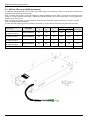
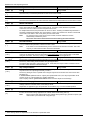
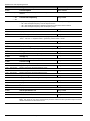
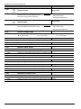
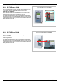
2.3 UB line filter up to 22kW (accessory)
An additional external line filter can be installed into the line supply of the frequency inverter to maintain the increased noise
suppression level (class B as per EN 55011).
When connecting the line filter, comply with Chapter 2.9 "Wiring guidelines" and 8.3 "EMC". In particular, ensure that the pulse
frequency is set to the default value (P504 = 4/6kHz) and that the maximum motor cable length (30m) is not exceeded and a
shielded motor cable is used.
Mains connection is by means of screw connections at the lower end of the filter. Inverter connection is by means of a fixed
cable of a suitable length (235-385mm).
The filter should be located as close as possible to the inverter; it can be used as a substructure or Book Size component.
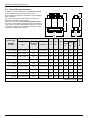
Detail: mounting
Filter type
Length
L1
Width
B1
Depth
T
Length L2
Width B2
Connection
cross-section
SK 700E-151-340-A …
SK 700E-401-340-A
SK LF1-460/14-F
281
121
48
268
100.5
6
SK 700E-551-340-A
SK 700E-751-340-A
SK LF1-460/24-F
331
121
58
318
100.5
6
SK 700E-112-340-A
SK 700E-152-340-A
SK LF1-460/45-F
382
163
73
369
140
10
SK 700E-182-340-A
SK 700E-222-340-A
SK LF1-460/66-F
431
201
73
418
172
16
Inverter type
All dimensions in mm
L1
10
L2
L3
mm
2
PE
Subject to technical alterations
BU 0700 GB-1411
2 Assembly and installation
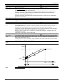
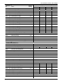
2.4 Chassis line filter (accessory)
In contrast to the line filter described in Chapter 2.3, the HLD 110 (up
to 110kW) has a UL acceptance for the North American market.
The interference noise suppression level of class A is achieved with
up to a maximum motor cable length of 50m, and class B with motor
cables of up to 25m.
When connecting the line filter, comply with Chapter 2.9 "Wiring
guidelines" and 8.3 "EMC". In particular, ensure that the pulse
frequency is set to the default value (P504 = 4/6kHz). The line filter
should be placed as close to the side of the inverter as possible.
The connection is by means of screw connections on the upper
(mains) and lower (inverter) ends of the filter
B2
L1 L
2 L3
Netz
/ LIN
E
L2
Gerä
t / LO
AD
L1
L1' L
2' L3
'
T
B1
Inverter type
Filter type
SK 700E ...
HLD 110 - ...
[V] / [A]
Detail: mounting
Length
L1
Width
B1
Depth
T
Length L2
Width B2
Connection
cross-section
...-151-340-A
...-221-340-A
… 500/8
190
45
75
180
20
4 mm
...-301-340-A
...-401-340-A
...-551-340-A
… 500/16
250
45
75
240
20
4 mm
...-751-340-A
...-112-340-A
… 500/30
270
55
95
255
30
10 mm
2
...-152-340-A
… 500/42
310
55
95
295
30
10 mm
2
...-182-340-A
… 500/55
250
85
95
235
60
16 mm
2
...-222-340-A
...-302-340-O
… 500/75
270
85
135
255
60
35 mm
2
...-372-340-O
… 500/100
...-452-340-O
...-552-340-O
270
95
150
255
65
50 mm
2
… 500/130
...-752-340-O
… 500/180
380
130
181
365
102
95 mm
2
...-902-340-O
...-113-340-O
… 500/250
450
155
220
435
125
150 mm
300
160
2 x 210
275
10.5mm
HFD 103-500/400 *
*) without UL/cUL
BU 0700 GB-1411
2
8.5mm
HFD 103-500/300 *
564
...-163-340-O
2
Bus bar
Design variant, without UL, only noise suppression level A
...-133-340-O
2
All dimensions in mm
Subject to technical alterations
11
NORDAC SK 700E Operating Manual
2.5 Line choke (accessories)
1
2
3
4
5
6
B2
L2
B1
L1
Input choke 3 x 380 - 480 V
Inverter type
NORDAC
SK 700E
Detail: mounting
Length Width Depth
Type
Permanent
current
Inductance
L1
B1
T
Length Width
L2
B2
1.5 ... 2.2 kW
SK CI1-460/6-C
6A
3 x 4.88 mH
71
125
140
55
100
M4
4
3.0 ... 4.0 kW
SK CI1-460/11-C
11 A
3 x 2.93 mH
84
155
160
56.5
130
M6
4
5.5 ... 7.5 kW
SK CI1-460/20-C
20 A
3 x 1.47 mH
98
190
201
57.5
170
M6
10
11 ... 18.5 kW
SK CI1-460/40-C
40 A
3 x 0.73 mH
118
190
201
77.5
170
M6
10
22 ... 30 kW
SK CI1-460/70-C
70 A
3 x 0.47 mH
124
230
220
98
180
M6
35
37 ... 45 kW
SK CI1-460/100-C
100 A
3 x 0.29 mH
148
230
290
122
180
M6
50
55 ... 75 kW
SK CI1-460/160-C
160 A
3 x 0.18 mH
170
299
360
105
237
M8
95
90 ... 132 kW
SK CI1-460/280-C
280 A
3 x 0.10 mH
190
290
270
133
240
M10
150
160 kW
SK CI1-460/350-C
350 A
3 x 0.084 mH
190
300
270
107
224
M8
CU Bar
All dimensions in [mm]
12
Connection
T
Mounting
To reduce input side current harmonics, additional inductivity
can be installed into the line supply to the inverter.
These chokes are specified for a maximum supply voltage of
480V at 50/60 Hz.
The protection class of the chokes is IP00 and they must
therefore be installed in a control cabinet.
For frequency inverters with an output of 45 kW or more, a
line choke is recommended where several devices are being
used, in order to avoid possible adverse effects of one device
on another. In addition, the charging currents (mains voltage
fluctuations) are significantly reduced.
Subject to technical alterations
2
[mm ]
BU 0700 GB-1411
2 Assembly and installation
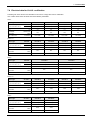
2.6 Output choke (accessories)
1
2
3
4
5
6
B2
L2
B1
L1
Output choke 3 x 380 - 480V
Inverter type
Detail: mounting
Length Width Depth
NORDAC
SK 700E
Type
Permanent
current
Inductance
B1
L1
T
Length Width
L2
B2
Connection
T
Mounting
To reduce interference signals from the motor cable or to
compensate for cable capacitance in long motor cables, an
additional output choke can be installed into the inverter
output.
Take care during installation that the pulse frequency of the
frequency inverter is set to 3-6kHz (P504 = 3-6).
These chokes are specified for a maximum supply voltage of
460V at 0-100 Hz.
An output choke should be fitted for cable lengths over
150m/50m (unshielded/shielded). Further details can be found
in Chapter 2.10.4 "Motor cable".
The protection class of the chokes is IP00 and they must
therefore be installed in a control cabinet.
1.5 kW
SK CO1-460/4-C
4A
3 x 3.5 mH
104
120
140
75
84
M6
4
2.2 ... 4.0 kW
SK CO1-460/9-C
9.5 A
3 x 2.5 mH
110
155
160
71.5
130
M6
4
5.5 ... 7.5 kW
SK CO1-460/17-C
17 A
3 x 1.2 mH
102
185
201
57.5
170
M8
10
11 ... 15 kW
SK CO1-460/33-C
33 A
3 x 0.6 mH
122
185
201
77.5
170
M8
16
18 ... 30 kW
SK CO1-460/60-C
60 A
3 x 0.33 mH
112
185
210
67
170
M8
35
37 ... 45 kW
SK CO1-460/90-C
90 A
3 x 0.22 mH
144
352
325
94
224
M8
35
55 ... 90 kW
SK CO1-460/170-C
170 A
3 x 0.13 mH
200
412
320
125
264
M10
CU bar
bolts
M12
110 … 132 kW
SK CO1-460/240-C
240 A
3 x 0.07 mH
225
412
320
145
388
M10
CU bar
bolts
M12
160 kW
SK CO1-460/330-C
330 A
3 x 0.03 mH
188
352
268
145
240
M10
CU bar
bolts
M16
All dimensions in [mm]
BU 0700 GB-1411
Subject to technical alterations
2
[mm ]
13
NORDAC SK 700E Operating Manual
2.7 UB brake resistors (accessory)
During dynamic braking (frequency reduction) of a three phase motor, electrical energy is returned to the frequency inverter. In
order to avoid overcurrent cut-off of the frequency inverter, the integrated brake chopper can convert the returned energy into
heat by connecting an external brake resistor.
For inverter outputs up to 7.5 kW, a standard substructure resistor can be fitted;
it can also be optionally equipped with a heat monitor for additional
thermal protection of the resistor.
This design is no longer possible with higher frequency
inverter outputs. Instead, the chassis brake
resistors (Chapter 2.8) can be used.
2.7.1 Electrical data UB BR
Inverter type
Resistor type
Resistance
Continuous
output (approx.)
*) Pulse output
(approx.)
Connection
leads, 500mm
SK 700E-151-340-A …
SK 700E-301-340-A
SK BR1-200/300-F
200
300 W
3 kW
2 x 0.75 mm
2
SK 700E-401-340-A
SK BR1-100/400-F
100
400 W
4 kW
2 x 0.75 mm
2
SK 700E-551-340-A
SK 700E-751-340-A
SK BR1- 60/600-F
60
600 W
7 kW
2 x 0.75 mm
2
*) permissible, depending on application, max. 5% ED
2.7.2 Dimensions UB BR
Fixing dimensions
Length
Width
Depth
L1
B1
T
Length L2
Width B2
SK BR1-200/300-F
281
121
48
269
100
5.2
SK BR1-100/400-F
281
121
48
269
100
5.2
SK BR1- 60/600-F
331
121
48
319
100
5.2
Resistor type
All dimensions in mm
14
Subject to technical alterations
BU 0700 GB-1411
2 Assembly and installation
2.8 Chassis brake resistors (accessory)
During dynamic braking (frequency reduction) of a three phase motor, electrical energy is released and returned to the
frequency inverter. To prevent a safety shut-down of the frequency inverter, the integrated brake
chopper can be activated by the connection of an external brake resistor.
The returned energy is converted into heat, so avoiding a possible overvoltage.
All chassis resistors are UL certified and are not subject to
restrictions in the North American market.
Connection is with screw connectors that are designated +B, B (1.5-22kW) or BR, +ZW (30-160kW), and the safety leads.
T
For overload protection, a thermal switch is located close to
a brake resistor. The switch is freely available via the
2
screw connectors (2 x 4mm ). The switching capacity is
limited to 250VAC/10A, 125VAC/15A and 30VDC/5A.
B1
B2
L2
L1
Basic diagram,
design varies according to output
2.8.1 Electrical data Chassis BR
Inverter type
Resistor type
Resistance
Continuous
output (approx.)
*) Pulse output
(approx.)
1.5 ... 2.2 kW
SK BR2- 200/300-C
200
300 W
3 kW
10 mm
2
3.0 ... 4.0 kW
SK BR2- 100/400-C
100
400 W
6 kW
10 mm
2
5.5 ... 7.5 kW
SK BR2- 60/600-C
60
600 W
9 kW
10 mm
2
11 ... 15 kW
SK BR2- 30/1500-C
30
1500 W
20 kW
10 mm
2
18.5 ... 22 kW
SK BR2- 22/2200-C
22
2200 W
28 kW
10 mm
2
30 ... 37 kW
SK BR2- 12/4000-C
12
4000 W
52 kW
10 mm
2
45 ... 55 kW
SK BR2- 8/6000-C
8
6000 W
78 kW
10 mm
2
75 ... 90 kW
SK BR2- 6/7500-C
6
7500 W
104 kW
25 mm
2
110 ... 160 kW
SK BR2- 3/7500-C
3
7500 W
110 kW
25 mm
2
NORDAC SK 700E
Connection
terminals
*) permissible, depending on application, max. 5% ED
2.8.2 Dimensions Chassis BR
Resistor type
SK BR2- 200/300-C
SK BR2- 100/400-C
Fixing dimensions
Length
Width
Depth
L1
B1
T
Length L2
Width B2
100
170
240
90
150
4.3
SK BR2- 60/600-C
350
92
120
325
78
6.5
SK BR2- 30/1500-C
560
185
120
530
150
6.5
SK BR2- 22/2200-C
460
270
120
430
240
6.5
SK BR2- 12/4000-C
560
270
240
530
240
6.5
SK BR2- 8/6000-C
470
600
300
440
2 x 220
6.5
570
600
300
540
2 x 220
6.5
SK BR2- 6/7500-C
SK BR2- 3/7500-C
All dimensions in mm
BU 0700 GB-1411
Subject to technical alterations
15
NORDAC SK 700E Operating Manual
2.9 Wiring guidelines
The frequency inverter has been developed for use in an industrial environment. In this environment, high levels of
electromagnetic interference can influence the frequency inverter. In general, correct installation ensures safe and problem-free
operation. To meet the limit values of the EMC directives , the following instructions should be complied with.
(1) Ensure that all equipment in the cabinet is securely earthed using short earthing cables that have large cross-sections and
which are connected to a common earthing point or earthing bar. It is especially important that every control device
connected to the frequency inverters (e.g. an automation device) is connected, using a short cable with large cross-section,
to the same earthing point as the inverter itself. Flat conductors (e.g. metal clamps are preferable, as they have a lower
impedance at high frequencies.
The PE lead of the motor controlled by the frequency inverter must be connected as directly as possible to the earth
connection of the cooling element, together with the PE of the corresponding frequency inverter mains supply. The presence
of a central earthing bar in the control cabinet and the grouping together of all PE conductors to this bar normally ensures
safe operation. (See also Chapter 8.3/8.4 EMC guidelines)
(2) Where possible, shielded cables should be used for control loops. The shielding at the cable end should be carefully sealed
and it must be ensured that the wires are not laid over longer distances without shielding.
The shields of analog setpoint cables should only be earthed on one side on the frequency inverter.
(3) The control cables should be installed as far as possible from power cables, using separate cable ducts, etc. Where cables
cross, an angle of 90° should be ensured as far as possible.
(4) Ensure that the contactors in the cabinet are interference protected, either by RC circuits in the case of AC contactors or by
free-wheeling diodes for DC contactors, for which the interference traps must be positioned on the contactor coils.
Varistors for over-voltage limitation are also effective. This interference suppression is particularly important when the
contactors are controlled by the relay in the frequency inverter.
(5) Shielded or protected cables should be used for load connections and the shielding/protection should be earthed at both
ends, if possible directly to the frequency inverter PE/shield angle.
(6) If the drive is to be used in an area sensitive to electromagnetic interference, then the use of noise suppression filters is
recommended to limit the cable-dependent and radiated interference from the inverter. In this case, the filter must be
mounted as closely as possible to the frequency inverter and fully earthed.
It is also an advantage if the inverter is installed together with the line filter in an EMC-proof enclosure, with EMC-compliant
cabling. (See also Chapter 8.3/8.4 EMC)
(7) Select the lowest possible switching frequency. This will reduce the intensity of the electromagnetic interference produced by
the frequency inverter.
The safety regulations must be complied with under all circumstances when installing the
frequency inverter!
Note
The control cables, line cables and motor cables must be laid separately. In no case should they be laid in
the same protective pipes/installation ducts.
The test equipment for high voltage insulations must not be used on cables that are connected to the
frequency inverter.
16
Subject to technical alterations
BU 0700 GB-1411
2 Assembly and installation
2.10 Electrical connections
2.10.1 Line and motor connections
WARNING
THESE DEVICES MUST BE EARTHED.
Safe operation of the devices presupposes that qualified personnel mount and operate it in compliance with
the instructions provided in these operating instructions.
In particular, the general and regional mounting and safety regulations for work on high voltage systems
(e.g. VDE) must be complied with as must the regulations concerning professional use of tools and the use
of personal protection equipment.
Dangerous voltages can be present at the line input and the motor connection terminals even when the
inverter is switched off. Always use insulated screwdrivers on these terminal fields.
Ensure that the input voltage source is not live before setting up or changing connections to the unit.
Make sure that the inverter and motor have the correct supply voltage set.
Note:
If synchronising devices are connected or several motors are switched in parallel, the frequency inverter must be
operated with linear voltage/frequency characteristic curves, P211 = 0 and P212 = 0.
The line, motor, brake resistor and control connections are located on the base of the device. To gain access to the terminals,
the device covers (cover and grid) must be removed. The connection terminals are now accessible from the front. All covers
must be put back in place before switching on the supply voltage!
In general, the line, motor and brake resistor cables are connected first as their terminals are located on the bottom circuit
board. The cable inlet is a slit opening on the base of the device.
Note:
when using specific wiring sleeves, the maximum connection cross-section can be reduced.
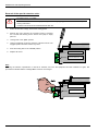
Pay attention to the following:
1.
Ensure that the voltage source provides the correct voltage and is suitable for the current required (see Chapter 7
Technical data). Ensure that suitable circuit breakers with the nominal current range are inserted between the voltage
source and the inverter.
2.
Connect the line voltage directly to the line terminals L 1 - L2 - L3 and the earth (PE).
3.
A four-core cable must be used to connect the motor. The cable must be connected to the motor terminals U - V - W and
the PE.
4.
If shielded cables are used, then the cable shield can also be applied to as much surface as possible on the shield support
angle.
Note: The use of shielded cables is essential in order to maintain the specified radio interference suppression level. (See
also Chapter 8.4 EMC limit value classes)
BU 0700 GB-1411
Subject to technical alterations
17
NORDAC SK 700E Operating Manual
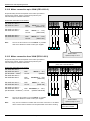
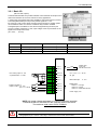
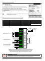
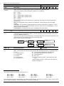
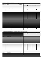
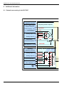
2.10.2 Mains connection up to 22kW (PE/L1/L2/L3)
No special safety devices are required on the mains input side for
the frequency inverter, just the normal mains protection (see
technical data) and a master switch/fuse.
Connection terminals cross-section:
SK 700E-151-340-A ...
SK 700E-751-340-A
SK 700E-112-340-A ...
SK 700E-152-340-A
SK 700E-182-340-A ...
SK 700E-222-340-A
VDE
UL/cUL
4mm² (0.5 … 0.6Nm)
(AWG 24-10)
PE L1 L2 L3
Input
+B -B -DC U V W PE
Brake
Output
VDE
10mm² (1.2 … 1.5Nm)
UL/cUL
(AWG 22-8)
VDE
25mm² (2.4 … 4.0Nm)
UL/cUL
(AWG 16-4)
M
3~
Note:
The use of this inverter on an IT network is possible
after minor alterations. Please consult your supplier.
PE L1 L2 L3
Brake resistor
Optional, Chap. 2.7/2.8
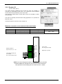
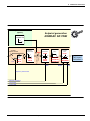
2.10.3 Mains connection from 30kW (PE/L1/L2/L3)
No special safety devices are required on the mains input side for
the frequency inverter, just the normal mains protection (see
technical data) and a master switch/fuse.
Some of the PE connections are in the support
plate, near to the terminal bar
Connection terminals cross-section:
SK 700E-302-340-O ...
SK 700E-372-340-O
2
(PE terminals = 16mm )
SK 700E-452-340-O ...
SK 700E-552-340-O
SK 700E-752-340-O …
SK 700E-902-340-O
VDE
UL/cUL
35mm² (6 … 8Nm)
(AWG 2)
VDE
UL/cUL
25-50mm² (6 … 8Nm)
(AWG 4-0)
VDE
UL/cUL
95mm² (15 … 20Nm)
(AWG 000)
PE L1 L2 L3
Input
-ZW BR +ZW PE
BR
U V W PE
Output
M
3~
SK 700E-113-340-O ...
SK 700E-163-340-O
VDE 50-150mm² (25 … 30Nm)
2
(PE terminals = 35-95mm ) UL/cUL
(AWG 0-300 MCM)
PE L1 L2 L3
Note:
Note:
18
The use of this inverter on an IT network is possible
after minor alterations. Please consult your supplier.
Only one PE terminal is located near the mains connection in the 90kW
device. Further PE connections can be implemented on the device housing.
Subject to technical alterations
Brake resistor
Optional, Chap. 2.7/2.8
Do not use ZW, the
connection is sealed.
BU 0700 GB-1411
2 Assembly and installation
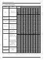
2.10.4 Motor cable (U/V/W/PE)
The motor cable must have a maximum length of 150m (Please note also Chapter 8.4 EMC limit value classes). If a shielded
motor cable is used, or the metallic cable duct is well earthed, the maximum length of 50m should not be exceeded. For longer
cable lengths , additional output chokes must be used.
For multiple motor use, the total cable length consists of the sum of the individual cable lengths. If the sum of the cable lengths
is too high, one output choke should be used per motor/cable.
Connection terminals cross-section:
SK 700E-151-340-A ... SK 700E-751-340-A
VDE
UL/cUL
4mm² (0.5 … 0.6Nm)
(AWG 24-10)
SK 700E-112-340-A ... SK 700E-152-340-A
VDE
UL/cUL
10mm² (1.2 … 1.5Nm)
(AWG 22-8)
SK 700E-182-340-A ... SK 700E-222-340-A
VDE
UL/cUL
25mm² (2.4 … 4.0Nm)
(AWG 16-4)
SK 700E-302-340-O ... SK 700E-372-340-O
2
(PE terminals = 16mm )
VDE
UL/cUL
35mm² (3.2 … 3.7Nm)
(AWG 2)
SK 700E-452-340-O ... SK 700E-752-340-O
(75KW: no PE terminal, screw terminal in the support plate)
VDE
UL/cUL
25-50mm² (6 … 8Nm)
(AWG 4-0)
SK 700E-902-340-O
(No PE terminals, screw terminal in the support plate)
VDE
UL/cUL
95mm² (15 … 20Nm)
(AWG 000)
SK 700E-113-340-O ... SK 700E-163-340-O
2
(PE terminals = 35-95mm )
VDE
50-150mm² (25 … 30Nm)
UL/cUL
(AWG 0-300 MCM)
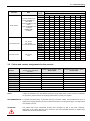
2.10.5 Brake chopper connection up to 22kW (+B/-B)
The connection for the frequency inverter brake resistor should be shielded and as short as possible.
Note:
Possible strong heating of the brake resistor should be taken into account.
Connection terminals cross-section:
SK 700E-151-340-A ... SK 700E-751-340-A
VDE
UL/cUL
4mm² (0.5 … 0.6Nm)
(AWG 24-10)
SK 700E-112-340-A ... SK 700E-152-340-A
VDE
UL/cUL
10mm² (1.2 … 1.5Nm)
(AWG 22-8)
SK 700E-182-340-A ... SK 700E-222-340-A
VDE
UL/cUL
25mm² (2.4 … 4.0Nm)
(AWG 16-4)
2.10.6 Brake resistor connection from 30kW (BR+ZW)
The connection for the frequency inverter brake resistor should be shielded and as short as possible.
Note:
Possible strong heating of the brake resistor should be taken into account.
Connection terminals cross-section:
Note:
16mm² (3.2 … 3.7Nm)
(AWG 6)
SK 700E-302-340-O ... SK 700E-372-340-O
2
(add. PE terminals = 16mm )
VDE
UL/cUL
SK 700E-452-340-O ... SK 700E-752-340-O
2
(add. PE terminals = 0.75-35mm )
VDE 0.75-35mm² (3.2 … 3.7Nm)
UL/cUL
(AWG 18-2)
SK 700E-752-340-O ... SK 700E-902-340-O
(No PE terminals, screw terminal in the support plate)
VDE
UL/cUL
50mm² (6 … 8Nm)
(AWG 4-0)
SK 700E-113-340-O ... SK 700E-163-340-O
2
(add. PE terminals = 95mm )
VDE
UL/cUL
95mm²(15 … 20Nm)
(AWG 000)
Only one PE terminal is located near the mains connection in the 90kW
device. Further PE connections can be implemented on the device housing.
BU 0700 GB-1411
Subject to technical alterations
19
NORDAC SK 700E Operating Manual
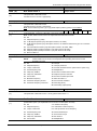
2.10.7 Control unit connection
The manner and type of control unit connections are dependent on the options chosen (customer unit / special extension unit).
The possible variations are described in Chapter 3.2/3.3.
On these pages you will find general data and information on all customer units and special extension units.
Connection terminals:
-
Plugs, terminals and connectors can be released with a small screwdriver
2
2
Maximum connection cross-section:
-
Cable:
-
Lay and shield separately from the mains/motor cables
Control voltages:
(Short-circuit proof)
-
5V for the supply of an incremental encoder
10V, max. 10mA, reference voltage for an external potentiometer
15V for the supply of the digital inputs or an incremental or absolute encoder
analog output 0 - 10V, max. 5mA for an external display unit
Note:
1.5 mm or 1.0 mm , depending on option
All control voltages are based on a common reference potential (GND).
5 / 15 V can if necessary, be taken from several terminals. The sum of the
currents is max. 300 mA.
20
Subject to technical alterations
BU 0700 GB-1411
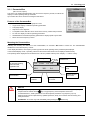
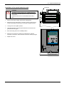
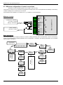
3 Operation and display
3
Operation and display
The NORDAC SK 700E basic device is supplied with a blanking cover for the technology unit slot and the basic version has no
components for parameterisation or control.
Technology units, customer units and special extension units
Through the combination of modules for the display, technology units and modules with digital and analog inputs, as well as
interfaces, customer units or special extension units, the NORDAC SK 700E can be easily adapted to the requirements of
various applications.
Technology Units (TU) are modules that can be inserted from above for display,
parameterisation and control of the inverter.
Customer Units (CU) are modules inserted inside the inverter in the upper recess.
They are used for control and communication using digital/analog signals or bus
interfaces.
Extension Units (XU) are inserted into the slot at the base of the inverter. Such an
extension unit is required if the speed is to be controlled or positioned by an incremental
(absolute) encoder.
WARNING
Modules should not be inserted or removed unless the device is free of voltage. The slots may only be used
for the applicable modules. The slots are coded to prevent them being mixed up.
BU 0700 GB-1411
Subject to technical alterations
21
NORDAC SK 700E Operating Manual
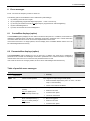
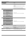
3.1 Technology unit
(Technology Unit, Option)
Technology units are snapped onto the inverter externally. They are for the control or parameterisation of the inverter and for
the display of current operating settings..
Technology unit
(SK TU1-...)
ParameterBox
SK TU1-PAR
ControlBox
SK TU1-CTR
Potentiometer
SK TU1-POT
CANbus module
SK TU1-CAN
Profibus module
SK TU1-PBR
Profibus module
SK TU1-PBR-24V
RS 232
SK TU1-RS2
CANopen module
SK TU1-CAO
DeviceNet module
SK TU1-DEV
InterBus module
SK TU1-IBS
AS interface
SK TU3-AS1
Description
Data
For text-driven initialisation, parameterisation, configuration
and control of the frequency inverter. Background illuminated
graphic display.
6 languages
Storage of 5 data sets
Help texts
Used for commissioning, parameterisation, configuration and
control of the frequency inverter.
4-figure, 7-segment
LED display
For direct control of the drive from the frequency converter.
Potentiometer 0 to 100%
ON / OFF / Reverse button
This option enables control of the SK 700E via the CANbus
serial port.
Baud rate: 500 KBit/s
Connector: Sub-D 9
This option enables control of the SK 700E via the Profibus
DP serial port.
Baud rate: 1.5 MBaud
Connector: Sub-D 9
This option enables control of the SK 700E via the Profibus
DP serial port. Operation requires an external 24V supply.
Baud rate: 12 MBaud
Connector: Sub-D 9
ext. +24V DC supply
This option enables control of the SK 700E via the RS 232
serial port, e.g. using a PC.
Connector: Sub-D 9
This option enables control of the SK 700E via the CANbus
serial port, using the CANopen protocol
Baud rate: up to 1 MBit/s
Connector: Sub-D 9
This option enables control of the SK 700E via the DeviceNet
serial port using the DeviceNet protocol.
Baud rate: 500 KBit/s
5-pin screw connector
This option enables control of the SK 700E via the InterBus
serial port.
Baud rate: 500 kBit/s (2Mbit/s)
Connector: 2 x Sub-D 9
Actuator-sensor interface is a bus system for the lower field
bus level, used for simple control tasks.
4 sensors / 2 actuators 5 / 8 pin
screw connector
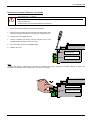
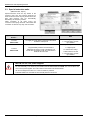
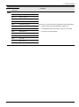
Mounting
The technology units must be installed as
follows:
1. Switch off the mains voltage,
observe the waiting period.
2.
Remove the blanking cover by
pressing the upper and lower
catches.
3.
Allow the technology unit to engage
audibly by pressing lightly on the
installation surface.
N O RD A C
700E
WARNING / NOTE
Modules must not be inserted or removed unless the device is free of voltage. The slots may only be used
for the applicable modules.
Installation of a technology unit separate from the frequency inverter is not possible. It must be connected
directly to the frequency inverter.
22
Subject to technical alterations
BU 0700 GB-1411
3.1 Technology unit
3.1.1 ParameterBox
(SK TU1-PAR, Option)
This option is for simple parameterisation and control of the frequency inverter, as well as the
display of current operating settings and states.
Up to 5 data sets can be stored and managed in this device.
Features of the ParameterBox
Illuminated, high resolution LCD graphics screen
Large-screen display of individual operating parameters
6 language display
Help text for error diagnosis
5 complete inverter data sets can be stored in the memory, loaded and processed
For use as a display for various operating parameters
Standardisation of individual operating parameters to display specific system data
Direct control of a frequency inverter
Mounting the ParameterBox
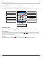
Following the mounting and switch-on of the ParameterBox, an automatic "Bus scan" is carried out. The ParameterBox
identifies the connected frequency inverter.
In the display that follows, the frequency inverter type and its actual operating status (if released) are displayed.
In the standard display mode, 3 operating values and the actual inverter status can be displayed simultaneously.
The operating values displayed can be selected from a list of 8 possible values (in the >Display< / > Values< menu).
Special extension unit
customer unit
Inverter type
Current actual values for
the selected operating
values and their
applicable units
700E
3,0kW/3
Fi/Hz
45.0
U/V
360
ONLINE
FI
POS STD
1
I/A
3.4
P1
Menu structure
level
R RUNNING
Actual status of
the inverter
Actual status of the
ParameterBox
Inverter
selected
Active parameters
in inverter
NOTE
The digital frequency setpoint is factory set to 0Hz. To check whether the motor is working, a frequency
setpoint must be entered with the
key or a jog frequency via the respective menu level
>Parameterization<, >Basic parameters< and the respective parameter >Jog frequency< (P113)
Settings should only be implemented by qualified personnel, strictly in accordance with the warning and
safety information.
ATTENTION : The motor may start immediately after pressing the
BU 0700 GB-1411
Subject to technical alterations
START key!
23
NORDAC SK 700E Operating Manual
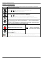
Functions of the ParameterBox
LCD display
Graphic-capable, backlit LCD display for displaying operating values and parameters for the connected
inverter and ParameterBox parameters.
Using the SELECTION keys to toggle between the menu levels and menu items.
Press the
and
keys together to go back one level.
The contents of individual parameters can be altered with the VALUES keys.
Press the
and
keys together to load the default values of the parameter selected.
When controlling the inverter using the keyboard, the frequency setpoint is set using the VALUE keys.
Press the ENTER key to select a menu group or accept the changed menu item or parameter value.
Note: If a parameter is to remain, without a new value being stored,
can be used for the purpose.
then one of the SELECTION keys
If the inverter is to be controlled directly from the keyboard (not control terminals), then the actual setpoint
frequency can be stored under the Jog Frequency parameter (P113).
START key for switching on the frequency inverter.
STOP key for switching off the frequency inverter.
The direction of rotation of the motor changes when the
DIRECTION key is operated. Rotation direction left is
indicated by a minus sign.
Attention! Take care when operating pumps, screw
conveyors, ventilators, etc.
DS
DE
24
Note:
Can only be used if this function
has not been blocked in parameter
P509 or P540.
The LED's indicate the actual status of the ParameterBox.
DS (ON (green))
The ParameterBox is connected to the power supply and is operational.
DE (ERROR (red)) An error has occurred while processing data or in the connected frequency inverter.
Subject to technical alterations
BU 0700 GB-1411
3.1 Technology unit
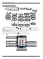
Menu structure
The menu structure consists of various levels that are each arranged in a ring structure. The ENTER key moves the menu on to
the next level. Simultaneous operation of the SELECTION keys moves the menu back a level.
700E 3,0kW/3 POS STD
Fi/Hz
45.0
ONLINE
Display
U/V
360
1
I/O
3.4
FI P1
R RUNNING
1
Parameter
management
P1201
Copy - Source
P1202
Copy - Target
U4
-
U5
-
Options
1
P1301
Language
2
P1302
Operating mode
2
1
2
2
Basic parameters 2
>ENTER<
(to level 3)
P1003
Display mode
U3
-
2
Operating displays 2
>ENTER<
(to level 3.)
P1002
FI selection
U2
-
1
Parameterization
P1001
Bus scan
U1
1
OK
100
2
P1303
2
Automatic bus scan
2
Motor data
>ENTER<
2
(to level 3)
P1203
Copy - Start
2
P1004
2
Values for display
P1304
Contrast
2
P1305
Set password
2
P1306
Box password
2
P1204
2
Load default values
P1005
Standardisation
factor
2
P0
Back
2
Inverter menu structure,
dependent on installed
options (e.g. posicion, etc.)
Section 5
Parameterisation
P1205
Delete memory
P0
Back
P0
Back
2
2
2
P1307
P0
2
zurückbox paramet.
Reset
P1308
P0
zurück
NORDAC
p-box
2
Version 3.9
P0
Back
2
>Display< (P10xx), >Parameter management< (P12xx) and >Options< (P13xx) are purely ParameterBox parameters and have
nothing directly to do with the inverter parameters.
Access to the inverter menu structure is gained via the >Parameterisation< menu. The details depend upon the customer units
(SK CU1-...) and/or special extension units (SK XU1-...) connected to the inverter. The description of parameterisation begins in
Chapter 5.
BU 0700 GB-1411
Subject to technical alterations
25
NORDAC SK 700E Operating Manual
Language selection, Summary
The following steps must be carried out to change the language used in the ParameterBox display.
The default setting is "German". After the mains supply is switched on, the following displays should appear (varies depending
upon output and options).
700E
Initial display
3,0kW/3
POS STD
1
> NORDAC <
Frequenzumrichter
ONLINE
FU P1
ESperre
1
Use the Selection keys
or
,
to scroll to the “Optionen“ menu
Optionen
>ENTER<
ONLINE
FU P1
ESperre
2
P1301
then press >ENTER<
Sprache
Deutsch ...
ONLINE
Using the Values key
select the “Sprache“
,
FU P1
ESperre
... English
... Français
... Espanol
... Sverige
... Nederlands
Nach Auswahl >ENTER<
betätigen
2
P1301
Language
English (e.g.)
ONLINE
Press the SELECTION keys
simultaneously
FI P1
Locked
and
1
Options
>ENTER<
ONLINE
Press the SELECTION keys
simultaneously
FI P1
Locked
and
700E
3,0kW/3
POS STD
1
> NORDAC <
Frequency Inverter
ONLINE
26
Subject to technical alterations
FI P1
Locked
BU 0700 GB-1411
3.1 Technology unit
Controlling the frequency inverter with the ParameterBox
The frequency inverter can only be completely controlled via the ParameterBox if the parameter >Interface< (P509) is set to the
>Keyboard< function (0 or 1) (the factory setting of the NORDAC SK 700E) and the inverter is not enabled via the control
terminal.
R
START (Enable)
No inverter
control function
STOP (Enable)
Increase frequency
vector
Change rotation direction
Decrease frequency
Store actual frequency
Note:
Attention:
If the inverter is enabled in this mode, then the parameter set to be used can be selected for this inverter in the
menu: >Parameterisation< ...>Basic Parameter< in the parameter >Parameter Set<.
If the parameter set has to be changed during operation, then the new parameter set must be selected in this
parameter and activated using the
keys.
After the START command, the inverter can start immediately or with a pre-programmed frequency (minimum
frequency P104 or jog frequency P113).
Parameterising with the ParameterBox
The parameter mode accessed is the one selected at menu item >Parameterisation< at Level 1 of the Parameter Box. The
parameter level of the connected inverter is accessed using the ENTER key.
The diagram below shows how the ParameterBox control elements are used for parameterisation.
SELECTION keys
R
Selection forward
Increase value
Simultaneous operation
one menu level back
Selection back
VALUE keys
Simultaneous activation:
load default parameters
vector
Reduce value
One menu level forward
or
accept parameter value
BU 0700 GB-1411
Subject to technical alterations
27
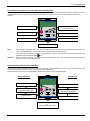
NORDAC SK 700E Operating Manual
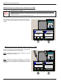
Screen layout during parameterisation
If the setting of a parameter is changed, then the value flashes intermittently until confirmed with the ENTER key. In order to
retain the factory settings for the parameter being edited, both VALUE keys must be operated simultaneously. Even in this case,
the setting must be confirmed with the ENTER key for the change to be stored.
If the change is not to be stored, then pressing one of the SELECTION keys will cal up the previously stored value. Further
operation of a VALUE key leaves this parameter.
Parameter set to be edited
Parameter to be edited (No.)
Parameter to be
edited (text)
Current parameter
value
ONLINE
FI P1
Menu
structure level
E BLOCK
Status of the
control medium
Actual status of the
ParameterBox
Note:
3
P102
PS1
Acceleration time
2,90 s
Selected
control medium
Active parameter set
in control medium
The lowest line in the display is used to display the current status of the box and the frequency inverter being
controlled.
3.1.1.1 ParameterBox parameters
The following main functions are assigned to the menu groups:
Menu group
No.
Master function
Display
(P10xx):
Selection of operating values and display layout
Parameterisation
(P11xx):
Programming of the connected inverter and all storage media
Parameter management
(P12xx):
Copying and storage of complete parameter sets from storage media and
inverters
Options
(P14xx):
Setting the functions of the ParameterBox, as well as all automatic processes
Parameter display
Parameter
Setting value / Description / Note
P1001
A bus scan is initiated with this parameter. During this process a progress indicator is shown in the
display.
After a bus scan, the parameter is "Off".
Depending on the result of this process, the ParameterBox goes into the "ONLINE" or "OFFLINE"
operating status.
Selection of the current item to be parameterised/controlled.
The display and further operating actions refer to the item selected. In the inverter selection list,
only those devices detected during the bus scan are shown. The actual object appears in the status
line.
Value range: FI, S1 ... S5
Selection of the operating values display for the ParameterBox
Standard
Any 3 values next to each other
List
Any 3 values with units below each other
Large display
1 value (any) with unit
Selection of a display value for the actual value display of the ParameterBox.
The value selected is placed in the first position of an internal list for the display value and is then
also used in the Large Display mode.
Possible actual values for the display: Speed of rotation Link voltage
Setpoint frequency
Torque current
Speed of rotation Current
Voltage
Actual frequency
Bus scan
P1002
Inverter select
P1003
Display mode
P1004
Values to display
28
Subject to technical alterations
BU 0700 GB-1411
3.1 Technology unit
Parameter
Setting value / Description / Note
P1005
The first value on the list displayed is scaled using the standardisation factor. If this standardisation
factor varies from a value of 1.00, then the units of the scaled value are hidden in the display.
Value range: -327.67 to +327.67; resolution 0.01
Scaling factor
Parameterisation
Parameter
Setting value / Description / Note
P1101
Selection of the item to be parameterised.
The ongoing parameterisation process relates to the object selected. Only the devices and storage
objects detected during the bus scan are displayed in the selection list.
Value range: FI, S1 ... S5
Object selection
Parameter administration
Parameter
Setting value / Description / Note
P1201
Selection of the actual source object to be copied.
In the selection list, only the frequency inverters and storage media detected during the bus scan
are shown.
Value range: FI, S1 ... S5
Selection of actual target object to copy.
In the selection list, only the frequency inverters and storage media detected during the bus scan
are shown.
Value range: FI, S1 ... S5
This parameter triggers a transfer process, whereby all the parameters selected in >Copy –
Source< are transferred to the object specified in the >Copy – Target< parameter.
While data is being overwritten, an information window appears with acknowledgement. The
transfer starts after acknowledgement.
In this parameter, the default settings are written to the parameters of the selected item.
This function is particularly important when editing storage objects. It is only via this parameter that
a hypothetical inverter can be loaded and processed with the ParameterBox.
Value range: FI, S1 ... S5
Copy - Source
P1202
Copy - Destination
P1203
Copy - Start
P1204
Load default values
P1205
Clear memory
In this parameter the data in the selected storage medium is deleted.
Value range: S1 ... S5
Options
Parameter
Setting value / Description / Note
P1301
Selection of languages for operation of the ParameterBox
Available languages:
German
English
Dutch
French
Spanish
Swedish
Selection of the operating mode for the ParameterBox
Offline:
The ParameterBox is operated autonomously. The data set of the frequency inverter is not
accessed. The storage objects of the ParameterBox can be parameterised and administrated.
Online:
A frequency inverter is located at the interface of the ParameterBox. The frequency inverter can be
parameterised and controlled. When changing to the “ONLINE” operating mode, a bus scan is
started automatically.
PC slave:
Only possible with the p-box or SK PAR-.. ParameterBox.
Setting the switch-on characteristics.
Off
No bus scan is carried out; the frequency inverters connected before disconnection are sought
when switched on again.
On
A bus scan is carried out automatically when the Parameter Box is switched on.
Language
P1302
Operating mode
P1303
Auto-bus-scan
BU 0700 GB-1411
Subject to technical alterations
29
NORDAC SK 700E Operating Manual
Parameter
Setting value / Description / Note
P1304
Contrast setting of the ParameterBox display
Value range: 0% ... 100%; Resolution 1%
Contrast
P1305
Set password
P1306
Box password
P1307
Reset Box parameter
P1308
NORDAC p-box
The user can set up a password in this parameter.
If a value other than 0 has been entered in this parameter, then the settings of the ParameterBox or
the parameters of the connected inverter cannot be altered.
If the Password function is to be reset, the password selected in the >Set Password< parameter
must be entered here. If the correct password has been selected, than all functions of the
ParameterBox can be used again.
In this parameter the ParameterBox can be reset to the default setting. All ParameterBox settings
and the data in the storage media will be deleted.
Displays the software version of the ParameterBox (NORDAC p-box). Please keep for future use.
3.1.1.2 ParameterBox error messages
Display
Cause
Error
Remedy
Communication error
200
INCORRECT PARAMETER NUMBER
201
PARAMETER VALUE CANNOT BE CHANGED
202
PARAMETER OUTSIDE VALUE RANGE
203
FAULTY SUB INDEX
204
NO ARRAY PARAMETERS
These error messages are due to EMC interferences or differing software
versions of the subscribers.
Check the software version of the ParameterBox and that of the connected
frequency inverter.
Check the cabling of all components, regarding possible EMC interference
205
WRONG PARAMETER TYPE
206
INCORRECT RESPONSE RECOGNITION
USS INTERFACE
207
USS INTERFACE CHECKSUM FAULT
208
FAULTY STATUS RECOGNITION USS
INTERFACE
209_1
INVERTER DOES NOT RESPOND
30
Communication between inverter and ParameterBox is disrupted (EMC), safe
operation cannot be guaranteed.
Check the connection to the frequency inverter. Use a shielded cable between
the devices. Route the BUS leads separately from the motor cables.
Communication between inverter and ParameterBox is disrupted (EMC), safe
operation cannot be guaranteed.
Check the connection to the frequency inverter.
Use a shielded cable between the devices. Route the BUS leads separately
from the motor cables.
The ParameterBox is waiting for a response from the connected frequency
inverter. The waiting time has elapsed without a response being received.
Check the connection to the frequency inverter.
The settings of the USS parameters for the frequency inverter were changed
during operation.
Subject to technical alterations
BU 0700 GB-1411
3.1 Technology unit
Display
Cause
Error
Remedy
Identification error
220
UNRECOGNISED DEVICE
221
SOFTWARE VERSION NOT RECOGNISED
222
CONFIGURATION STAGE NOT
RECOGNISED
223
BUS CONFIGURATION HAS CHANGED
224
DEVICE NOT SUPPORTED
225
THE CONNECTION TO THE INVERTER IS
BLOCKED
Device ID not found.
The connected inverter is not listed in the database of the ParameterBox; no
communication can be established.
Please contact your Getriebebau Nord dealership.
Software version not found.
The software of the connected inverter is not listed in the ParameterBox
database, no communication can be set up.
Please contact your Getriebebau Nord dealership.
An unknown component has been detected in the frequency inverter (Customer
unit / Special extension unit).
Please check the components installed in the frequency inverter
If necessary check the software version of the ParameterBox and the
frequency inverter.
A different device to that saved responds when the last bus configuration is
restored.
This error can only occur if the parameter >Auto. Bus Scan< is set to OFF and
another device has been connected to the ParameterBox.
Activate the Automatic Bus Scan function.
The inverter type entered in the ParameterBox is not supported!
The ParameterBox cannot be used with this inverter.
Access to a device that is not online (previously Time Out error).
Carry out a bus scan via the parameter >Bus Scan< (P1001).
ParameterBox operating error
226
SOURCE AND TARGET ARE DIFFERENT
DEVICES
Copying objects of different types (from / to different inverters) is not possible.
227
Copying of data from a deleted (empty) storage medium
SOURCE IS EMPTY
228
THIS COMBINATION IS NOT PERMITTED
Target and source for the copying function are the same. The command cannot
be carried out.
229
Parameterisation attempt of a deleted storage medium
THE SELECTED ITEM IS EMPTY
230
DIFFERENT SOFTWARE VERSIONS
231
INVALID PASSWORD
232
BUS SCAN ONLY WHEN IN ONLINE MODE
ONLINE
BU 0700 GB-1411
Warning
Copying objects with different software versions can lead to problems when
transferring parameters.
Attempt to alter a parameter without a valid Box password being entered in
parameter >Box Password< P 1306.
A bus scan (search for a connected frequency inverter) is only possible when in
ONLINE mode.
Subject to technical alterations
31
NORDAC SK 700E Operating Manual
Display
Cause
Error
Remedy
Warnings
240
241
OVERWRITE DATA?
YES
NO
DELETE DATA?
YES
NO
242
MOVE SW VERSION?
CONTINUE
CANCEL
243
MOVE SERIES?
CONTINUE
244
These warnings indicate that there is a possibly significant change which needs
additional confirmation.
Once the next procedure has been selected, it must be confirmed with the
"ENTER" key.
CANCEL
DELETE ALL DATA?
YES
NO
Inverter control error
250
THIS FUNCTION IS NOT ENABLED
251
CONTROL COMMAND WAS NOT
SUCCESSFUL
252
CONTROL OFFLINE NOT POSSIBLE
253
ERROR ACKNOWLEDGEMENT NOT
SUCCESSFUL
The function requested is not enabled at the frequency inverter parameter
interface.
Change the value of the parameter >Interface< of the connected inverter to
the required function.
More detailed information can be obtained from the operating instructions for
the frequency inverter.
The control command could not be implemented by the inverter, as a higher
priority function, e.g. Emergency Stop or an OFF signal to the control terminals of
the inverter, is present
Call up of a control function in Offline mode.
Change the operating mode of the p-box in the parameter >Operating Mode<
P1302 to Online and repeat the action.
The acknowledgement of an error at the frequency inverter was not successful,
the error message remains.
Error message from inverter
"ERROR No. FROM INVERTER"
INVERTER FAULT "INVERTER FAULT TEXT"
32
An error has occurred at the frequency inverter with the displayed number. The
inverter error number and text are displayed.
Subject to technical alterations
BU 0700 GB-1411
3.1 Technology unit
3.1.2 ControlBox
(SK TU1-CTR, Option)
This option is used for the parameterisation and control of the frequency inverter.
Features
4-figure, 7 segment LED display
Direct control of a frequency inverter
Display of the active parameter set.
Storage of a complete frequency inverter parameter set (P550)
After mounting of the ControlBox and the switching on of the mains supply, horizontal
dashes are displayed in the 4 figures of the 7 segment display. This display shows the
operational readiness of the frequency inverter.
If the inverter is switched to enable, the display changes automatically to the operating value selected in parameter >Selection
Display value< P001(default setting = actual frequency).
The actual parameter set is shown by the 2 LEDs next to the display on the left in binary code.
NOTE
The digital frequency setpoint is factory set to 0Hz. To check whether the motor is working, a frequency
setpoint must be entered with the
key or a jog frequency via the respective parameter >Jog
frequency< (P113).
Settings should only be implemented by qualified personnel, strictly in accordance with the warning and
safety information.
ATTENTION : The motor may start immediately after pressing the
START key!
ControlBox functions:
Press to switch on the frequency inverter. The frequency inverter is now enabled with the set jog frequency
(P113). A preset minimum frequency (P104) may at least be provided. Parameter >Interface< P509 must =
0.
Press to switch off the frequency inverter. The output frequency is reduced to the absolute minimum
frequency (P505) and the frequency inverter shuts down at the output side.
7-segment
LED display
LEDs
Shows the current operating value set during operation (selection in P001) or an error code. During
parameterisation, the parameter numbers or the parameter values are shown.
The LEDs indicate the actual operating parameter set in the operating display (P000) and the actual
parameter set being parameterised during parameterisation. Tin this case the display is coded in binary
form.
1
1
2
2
1
1
= P1
= P2
1
= P3
2
2
= P4
2
The motor rotation direction changes when this key is pressed. "Rotation to the left" is indicated by a minus
sign. Attention! Take care when operating pumps. screw conveyors, ventilators, etc. Block the key with
parameter P540.
Press the key to INCREASE the frequency. During parameterisation, the parameter number or parameter
value is increased
Press the key to REDUCE the frequency. During parameterisation, the parameter number or parameter
value is reduced.
Press "ENTER" to store an altered parameter value, or to switch between parameter number or parameter
value.
NOTE: If a changed value is not to be stored, the
the change.
BU 0700 GB-1411
key can be used to exit the parameter without storing
Subject to technical alterations
33
NORDAC SK 700E Operating Manual
Controlling the frequency inverter with the ControlBox
The inverter can only be controlled via the ControlBox, if it has not previously been enabled via the control terminals or via a
serial interface (P509 = 0).
If the "START" key is pressed, the inverter in the operating display changes (selection P001).
The frequency inverter supplies 0Hz or a minimum frequency (P104) or jog frequency (P113) that has been set at a higher level.
R
Parameter set display
Quick stop
(press simultaneously)
START
STOP
Change rotation direction
Store current frequency
as jog frequency
vector
Decrease frequency
Increase frequency
Set frequency = 0Hz
(press simultaneously)
Parameter set display:
The LEDs indicate the actual operating parameter set in the operating display (P000) and the current parameter set being
parameterised ( P000). There, the display appears in binary form.
The parameter set can also be changed during operation via the parameter P100 (control via ControlBox).
Frequency setpoint:
The current frequency setpoint depends on the setting in the parameters jog frequency (P113) and minimum frequency (P104).
This value can be altered during keyboard operation with the value keys
jog frequency by pressing the ENTER key.
and
and permanently stored in P113 as the
Quick stop:
By simultaneously pressing the STOP key
and the "Change direction key”
34
Subject to technical alterations
, an quick stop can be initiated.
BU 0700 GB-1411
3.1 Technology unit
Parameterisation with the ControlBox
The parameterisation of the frequency inverter can be performed in the various operating states. All parameters can always be
changed online. Switching to the parameter mode occurs in different ways depending upon the operating states and the
enabling source.
1.
If there is no enable (if necessary, press the STOP key
) via the ControlBox, control terminals or a serial interface, it is
still possible to switch to the parameterisation mode directly from the operating value display with the value keys
P0__ / P 7 _ _
2.
or
.
If an enable is present via the control terminals or a serial interface and the inverter is producing an output frequency, it is
also possible to switch to the parameterisation mode directly from the operating value display using the value keys
or
. P 0 _ _ / P7__
3.
If the inverter is enabled via the ControlBox (START key
START and ENTER keys
4.
+
), the parameterisation mode can be reached by pressing the
simultaneously.
Switching back to the control mode is achieved by pressing the START key
.
R
Parameter set display
Switching from control to
parameterisation while
the drive is running
(see Point 3)
Switching from
parameterisation to
control (see Point 3)
Select menu group,
display parameter value
Previous menu group or
parameter number
Next menu group or
parameter number
vector
One level each time back to
the operating value display
Parameterisation of the frequency inverter
To access the parameter section, one of the value keys,
or
must be pressed. The display changes to the menu group
display
P 0 _ _ ... P 7 _ _. Once the required menu group has been reached, the ENTER key
must be pressed to access
the individual parameters.
All parameters are arranged in order in the individual menu groups in a continuous scroll pattern. It is therefore possible to scroll
forwards and backwards within this section.
Each parameter has a parameter number P x x x. The significance and description of the parameters starts in Chapter 5
"Parameterisation"
Note:
The parameters P542, P701 to 706, P707, P718, P741/742 and P745/746 also have an array level in which further
settings can be made, e.g.:
P542
ENTER
P_ 0 1
ENTER
0.0
Setting:
Value of leading function 1
ENTER
0.0
Setting:
Value of leading function 2
VALUE
P_ 0 2
BU 0700 GB-1411
Subject to technical alterations
35
NORDAC SK 700E Operating Manual
Menu structure with the SimpleBox
Operating values display
(or operational)
following mains ON
P7- -
_ _ _ _
P0 - P0 0 1
P0 0 2
P6- P5- P4- -
P1- -
P2- -
P3- P40 0
P10 0
P20 0
P30 0
P40 1
P10 1
P20 1
P30 1
P460
P114
P216
To change a parameter value, the ENTER key
P330
must be pressed when the applicable parameter number is displayed.
Changes can then be made using the VALUE keys
or
and must be confirmed with
to save them and leave the
parameter.
As long as a changed value has not been confirmed by pressing ENTER, the value display will flash; this value has not yet been
stored in the frequency inverter.
During parameter changes, the display does not blink so that the display is more legible.
If a change is not to be saved, the "DIRECTION" key
can be pressed to leave the parameter.
R
Parameter set display
Do not save changed
value
Reduce value
Accept changed values
vector
Increase value
Value to factory setting
36
Subject to technical alterations
BU 0700 GB-1411
3.1 Technology unit
3.1.3 PotentiometerBox
(SK TU1-POT, Option)
The PotentiometerBox can be used as a control unit for various functions. Selection can be
carried out in parameter P549.
In the basic setting direct control of the output frequency within the minimum (P104 =0 Hz)
and maximum frequency (P105 = 50 Hz) range is possible.
Note:
The frequency inverter can then only be controlled via the PotentiometerBox,
when the parameter >Interface< is programmed for the control terminals or
keyboard (P509 = 0) and if it has not previously been enabled via the control
terminals.
Control (with P549 = 1):
To switch on the frequency inverter, the START key
must be pressed. The frequency inverter is now
enabled with the actual potentiometer setting. Any previously set minimum frequency (P104) is the minimum
supplied.
To switch off the frequency inverter, the STOP key
the brake ramp (P103) until standstill.
must be pressed. The output frequency is reduced by
Change of rotation direction: When the inverter is enabled, the direction of rotation can be changed by long pressing (approx.
3s) of the START key
.
If the frequency inverter has not been enabled, the rotation direction with which the motor should be started can be changed by
a long press of the STOP key
.
Frequency setpoint:
A setpoint between the minimum frequency (P104) and the maximum frequency (P105) can be set with the potentiometer.
Error acknowledgement: If an inactive error of the frequency inverter is present (red LED flashing), it can be acknowledged by
pressing the STOP key
LED display:
Red LED
Green LED
BU 0700 GB-1411
off
No error
flashing
Inactive error
on
Active error
off
Frequency inverter switched off, enabled with rotation
direction to the right
flashing 1:
short on, long off
Frequency inverter switched off, enabled with rotation
direction to the left
flashing 2:
short on, short off
Frequency inverter switched on, with rotation
direction to the left
on
Frequency inverter switched on, with rotation
direction to the right
Subject to technical alterations
37
NORDAC SK 700E Operating Manual
3.1.4 RS 232 Box (SK TU1-RS2)
The RS 232 technology unit enables simple connection (cable: RS 232,
P. No. 78910030) from a NORDAC SK 700E to a PC with serial interface.
Communication between PC and frequency inverter can be
RXD
achieved using the NORD CON Software (Windows).
TXD
0V
Note: When using a standard I/O (SK CU1-STD Chap.
3.2.2), the RS485 termination resistor should be switched off
1
5
to prevent possible communication problems.
9
6
The connected inverter can be controlled and parameterised
via this interface. This allows a simple functional test of the
5V
inverter to be implemented and, following successful
parameterisation, the data set can be saved as a file.
Status
LEDs
TxD (green)
Data traffic on the send cable
RxD (green)
Data traffic on the receive cable
3.1.5 CANbus module (SK TU1-CAN)
The CANbus interface on the NORDAC frequency inverter enables parameterisation and control
of the device as per the CAN specifications 2.0A and 2.0B. Up to 512 participants can be
addressed on a single Bus. A termination resistor is integrated and can be switched on.
The transfer rate can be set between 10kBaud and
GND
CAN_L
500kBaud.
The collision and error recognition integrated in the CANbus
5
1
protocol enables maximum bus usage and data security.
6
9
Detailed information can be found in the operating
instructions BU 0060, or contact the supplier of the frequency
GND
CAN_N
inverter.
Status
LEDs
CAN_TxD (green)
Data traffic on the send cable
CAN_RxD (green)
Data traffic on the receive cable
Termination resistor
switched on
not switched on
3.1.6 Profibus module (SK TU1-PBR)
A large number of different automation devices can exchange data using Profibus. PLC's, PC's,
operating and monitoring devices can all communicate via a uniform bus in serial bit mode.
Data exchange is specified in DIN 19245 Part 1 and 2 and application-specific upgrades in Part 3
of this standard. Within the European field bus
GND
standardisation process, Profibus is integrated into the
European field bus standard pr EN 50170.
RTS
The termination resistor for the last bus participant is
B Data
located in the Profibus standard plug.
Detailed information can be found in the operating
1
5
instructions BU 0020 or contact the supplier of the
9
6
frequency inverter.
+5V
A Data
Status
LEDs
38
BR (green)
BE (red)
Bus Ready, normal operation, cyclical data transmission
Bus Error, interrupted data traffic, details in BU 0020
Subject to technical alterations
BU 0700 GB-1411
3.1 Technology unit
3.1.7 Profibus 24V module (SK TU1-PBR-24V)
Profibus allows numerous different automation devices to exchange data. PLC's, PC's, operating
and monitoring devices can all communicate via a uniform bus in serial bit mode. This Profibus
option is supplied via an external 24V DC 25% connection with
voltage.
GND
The Profibus subscriber can therefore be identified by the
RTS
master system even without a power supply to the
B Data
frequency inverter. The data required for this (PPO type
and Profibus address) are provided via a rotary coding
switch.
1
5
Data exchange is specified in DIN 19245 Part 1 and 2 and
9
6
application-specific upgrades in Part 3 of this standard.
Within the European field bus standardisation process,
+5V
Profibus is integrated into the European field bus standard
A Data
pr EN 50170.
The termination resistor for the last bus participant is
located in the Profibus standard plug.
Note:
The settings made using the rotary coding switch are not transferred to the frequency inverter. Detailed information
can be found in the operating instructions BU 0020.
Status
LEDs
BR (green)
BE (red)
Bus Ready, normal operation, cyclical data transmission
Bus Error, interrupted data traffic, details in BU 0020
3.1.8 CANopen module (SK TU1-CAO)
The CANopen interface on the NORDAC frequency inverter enables the parameterisation and
control of the devices in accordance with CANopen specifications.
Up to 127 participants can be addressed on a single Bus. A termination resistor is integrated and
can be switched on.
The transfer rate (10kBaud and 500kBaud) and the Bus
GND
CAN_L
addresses are set using rotary coding switches or the
5
1
applicable parameters.
Detailed information can be found in the operating
instructions BU 0060, or contact the supplier of the frequency
inverter.
CANopen
Status LEDs
CR (green)
CANopen RUN LED
CE (red)
CANopen ERROR LED
6
9
24V in
CAN_N
GND
Module
status LEDs
DR (green)
Module status
DE (red)
Module error
3.1.9 DeviceNet module (SK TU1-DEV)
MS (red/green)
Module status
MS (red/green)
Mains (bus) status
BU 0700 GB-1411
Module status
LEDs
Subject to technical alterations
V+
CAN_H
SHIELD
V-
DeviceNet
status LEDs
CAN_L
DeviceNet is an open communications profile for distributed industrial automation systems. It is
based on the CAN Bus system.
Up to 64 participants can be linked to one Bus system.
1 2 3 4 5
The transfer rate (125, 250, 500 kBit/s) and the Bus addresses
are set using rotary coding switches or the applicable parameters.
Detailed information can be found in the operating instructions BU
0080, or contact the supplier of the frequency inverter.
Voltage V+: 24V=
DS (green)
Module status
DE (red)
Module error
39
NORDAC SK 700E Operating Manual
3.1.10 InterBus module (SK TU1-IBS)
With InterBus up to 256 participants with different automation devices can exchange data.
PLC's, PC's, operating and monitoring devices can all communicate via a uniform bus in serial
bit mode.
NORDAC frequency inverters are remote bus participants. The data width is variable (3 words; 5
words), at a baud rate of 500kBit/s (optional 2Mbit/s). An additional termination resistor is not
necessary as it is already integrated. Addressing is carried out automatically by means of the
physical arrangement of the participants.
An external 24V supply is required for uninterrupted Bus operation.
Detailed information can be found in the operating instructions BU 0070, or contact the supplier
of the frequency inverter.
DI
DO
+5V_OUT GND
(100mA)
GND
1
9
/DO
DO
1
9
6
/DI
/DI
IBS-OUT
DI
5
5
6
IBS-IN
/DO
3.1.11 AS interface (SK TU1-AS1)
The Actuator-Sensor-Interface (AS interface) is a bus system for the simple field bus level. The
transmission principle is a single master system with cyclical polling. A maximum of 31 slaves
(or 62 A/B slaves) can be operated on an up to 100m long unshielded two-wire cable in any
network structure (tree/line/star). The AS interface cable (yellow) transmits data and energy
while a second two-wire cable can be used for a small auxiliary voltage (24V). Addressing is
implemented via the master, which can also provide other management functions, or via a
separate addressing device. The 4 bit reference data (per direction) are cyclically transmitted
with an effective error protection at a maximum cycle time of 5ms.
Detailed information can be found in the operating instructions BU 0090, or contact the supplier
of the frequency inverter.
The SK 700 E supports the AS interface technology unit from software version 3.1 Rev. 1
(P707 / P742).
Status LEDs
Digital I/O LEDs
AS-I I/O LEDs
40
Dig In 3
Device S/E (red/green)
AS- Int. PWR/FLT (red/green)
OUT 1 … 2 (yellow)
IN 1 ... 4 (yellow)
DI 1 ... 4 (yellow)
DO 1 ... 4 (yellow)
1
2
3
4
5
AUX GND
Dig In 2
8
AUX 24V
Dig In 1
7
n.c.
AUX GND
6
PWR AS-I (-)
5
PWR AS-I (+)
4
Dig Out 2
3
Dig Out 1
2
Connector 2 (PWR/AUX)
Dig In 4
1
AUX 24V
Connector 1 (I/O)
Module status/error.
Standard status display for AS interface slaves.
Status of the AS interface bits
received/transmitted from the Master.
Status at digital input/output.
Subject to technical alterations
BU 0700 GB-1411
3.2 Customer unit
3.2 Customer units
(Customer Units, Option)
Customer units are optional push-in modules whose slots are
located inside the frequency inverter. Following insertion and
switching on the mains supply, they are automatically identified
by the inverter, and the required parameters are made available.
Cable connection is via direct plug-in clip connectors with spring
terminals. This makes the connection of devices very easy and
convenient.
Customer unit
Description
SK CU1-...
Basic I/O
SK CU1-BSC
Data
1 x multifunction relays
Simplest custom interface for optimum adaptation to the
application.
3 x digital inputs
1 x analog input, 0...10V
2 x multifunction relays
4 x digital inputs
Standard I/O
SK CU1-STD
Upgraded functionality of control signals, including USS
bus control.
1 x analog input, 0...10V,
0/4...20mA
1 x analog outputs, 0...10V
1 x RS 485
2 x multifunction relays
Multi I/O
SK CU1-MLT
6 x digital inputs
Top functionality of digital and analog signal processing.
2 x analog inputs, -10...+10V,
0/4...20mA
2 x analog outputs, 0...10V
2 x multifunction relays
Multi I/O
SK CU1-MLT-20mA
6 x digital inputs
Top functionality of digital and analog signal processing.
2 x analog inputs, -10...+10V,
0/4...20mA
2 x analog outputs, 0/4...20mA
Profibus
SK CU1-PBR
CAN bus
SK CU1-CAN-RJ
1 x multifunction relays
This interface enables control of the NORDAC SK 700E
via the Profibus DP serial port.
1 x digital inputs
1 x Profibus
1 x multifunction relays
This unit enables control of the NORDAC SK 700E via
the CANbus port.
5 x digital inputs
2 x CANbus connectors RJ45
NOTE, for 5V / 15V power supplies
The customer units and special extension units currently have various power supplies (5V / 15V) that can
be used externally. The maximum permissible external load current is 300mA. This can be taken from
one or more power supplies. The total current must however not exceed 300mA.
All control voltages are based on a common reference potential!
Potentials AGND /0V und GND /0V are internally linked in the device.
BU 0700 GB-1411
Subject to technical alterations
41
NORDAC SK 700E Operating Manual
Motor temperature protection
- applies to all customer units! -
For secure protection against motor overheating, a temperature sensor (PTC
thermistor (PTC, PTC) can be connected to any digital input (excluding multi-I/O).
The appropriate parameters (P420 ... P423 or P425, depending on option) must be
set to a value of 13 (PTC thermistor input) for this purpose.
NOTE: With multi I/O only digital input 6 (P425) is possible!
Supply voltage +5V
The supply voltage varies dependent upon the customer unit. The lowest voltage
possible should be chosen.
Internal switching in the inverter prevents excessive PTC voltage.
The cable routing should always be separate from the motor cable and with
shielded cables.
Digital input
Motor
PTC
Installation of the customer unit:
WARNING / NOTE
Installation must be carried out by qualified personnel only, paying particular attention to safety and warning
instructions.
Customer units must not be inserted/removed when live.
1.
2.
3.
4.
5.
6.
7.
Switch off the mains voltage, observe the waiting period.
Remove the cover grid from the connection area by loosening the 2 screws and
levering out the device cover (slot, see Fig.) or simply pull it out.
Move the locking lever to the "open" position.
Using light pressure, push the customer unit into the upper guide rail until it
engages and lies flush with the plastic frame.
Move the locking lever to the "closed" position.
Remove the connector by pressing the releases then make the necessary
connections. Then insert the connectors until they engage.
Replace all covers.
Locking pin
Technology unit
Customer unit
Special extension unit
Locking device open
OPEN
CLOSED
Locking device closed
42
Subject to technical alterations
BU 0700 GB-1411
3.2 Customer unit
Removal of customer interfaces, up to 22kW:
WARNING / NOTE
Installation must be carried out by qualified personnel only, paying particular attention to safety and
warning instructions.
Customer units must not be inserted/removed when live.
1.
Switch off the mains voltage, observe the waiting period.
2.
Remove the cover grid from the connection area by loosening the 2
screws and levering out the device cover (slot) or simply pull it out.
3.
Locking lever in the "open" position.
4.
Using a screwdriver (as shown), lever the customer unit out of its
engaged position and then remove it by hand.
5.
Move the locking lever to the "closed" position.
6.
Replace all covers.
Customer unit
Special extension unit
Note:
Following the insertion, replacement or removal of modules, and once the equipment has been switched on again, this
procedure is indicated with the message E017 Customer unit changed.
Customer unit
Special extension unit
BU 0700 GB-1411
Subject to technical alterations
43
NORDAC SK 700E Operating Manual
Different position of customer units, in devices from 30 kW:
WARNING / NOTE
Installation must be carried out by qualified personnel only, paying particular attention to safety and
warning instructions.
Customer units must not be inserted/removed when live.
The procedure is as described above; however no locking lever
is present. The modules engage on the front edge when they are
inserted.
Getriebebau NORD
Getriebebau NORD
GmbH & Co. KG
D-22941 Bargteheide / Germany
GmbH & Co. KG
D-22941 Bargteheide / Germany
Typ/Part-No/ID:
SK_CU1_MLT 7820051/10C195890
Typ/Part-No:
Input:
2 x analog
6 x digital
2 x analog
2 x relay
Input:
Output:
Interface:
X10.1
X10.2
X10.3
X10.3
5 DIG IN 1
6 DIG IN 2
7 DIG IN 3
8 DIG IN 4
9 DIG IN 3
10 DIG IN 4
11 +15V
12 0V / GND
13 SSI CLK+
14 SSI CLK15 SSI DAT+
16 SSI DAT-
17 +5V
18 0V / GND
19 SPUR A+
20 SPUR A21 SPUR B+
22 SPUR B23 SPUR N+
24 SPUR N-
21 DIG IN 1
22 DIG IN 2
23 DIG IN 3
24 DIG IN 4
25 DIG IN 5
26 DIG IN 6
42 VO +15V
41 VO +5V
AIN 2
0/4...20mA (ON)
-10/0...10V (OFF)
11 VREF 10V
12 AGND/0V
14 AIN 1 +
16 AIN 2 +
17 AOUT1
18 AOUT2
40 GND/0V
4 REL2.2
3 REL2.1
0/4...20mA (ON)
-10/0...10V (OFF)
2 REL1.2
X2.3
X2.2
AIN 1
15V / 24V
5A 250V~/AC1
A,B,N
RS422
DAT/CLK RS422
Special
extension unit
1
2
3
4
X2.1
SK_XU1_POS 7820055/10C195890
6 x digital
2 x relay
1 x encoder
1 x SSI
REL1.1
REL1.2
REL2.1
REL2.2
Customer
unit
Output:
1 REL1.1
-10...10V / 0...20mA
15V / 24V
0...10V
5A 250V~/AC1
... Different removal of the customer units, for devices > 30 kW:
As shown, simply lever out from the upper edge. If this is difficult,
simply undo the locking hook on the front edge.
NOTE: Ensure that the mains voltage is switched off and that
sufficient waiting time has expired.
NOTE: Following the insertion, replacement or removal of
modules, and once the equipment has been switched on again,
this procedure is indicated with the message E017 Customer unit
changed.
Getriebebau NORD
GmbH & Co. KG
D-22941 Bargteheide / Germany
SK_CU1_MLT 7820051/10C195890
Typ/Part-No:
Input:
2 x analog
6 x digital
2 x analog
2 x relay
Input:
Output:
Interface:
Subject to technical alterations
SK_XU1_POS 7820055/10C195890
6 x digital
2 x relay
1 x encoder
1 x SSI
15V / 24V
5A 250V~/AC1
A,B,N
RS422
DAT/CLK RS422
X10.1
X10.2
X10.3
X10.3
1 REL1.1
2 REL1.2
3 REL2.1
4 REL2.2
5 DIG IN 1
6 DIG IN 2
7 DIG IN 3
8 DIG IN 4
9 DIG IN 3
10 DIG IN 4
11 +15V
12 0V / GND
13 SSI CLK+
14 SSI CLK15 SSI DAT+
16 SSI DAT-
17 +5V
18 0V / GND
19 SPUR A+
20 SPUR A21 SPUR B+
22 SPUR B23 SPUR N+
24 SPUR N-
Special
extension unit
AIN 2
0/4...20mA (ON)
-10/0...10V (OFF)
11 VREF 10V
12 AGND/0V
14 AIN 1 +
16 AIN 2 +
17 AOUT1
18 AOUT2
40 GND/0V
0/4...20mA (ON)
-10/0...10V (OFF)
4 REL2.2
3 REL2.1
2 REL1.2
X2.3
X2.2
AIN 1
21 DIG IN 1
22 DIG IN 2
23 DIG IN 3
24 DIG IN 4
25 DIG IN 5
26 DIG IN 6
42 VO +15V
41 VO +5V
X2.1
1 REL1.1
-10...10V / 0...20mA
15V / 24V
0...10V
5A 250V~/AC1
Customer
unit
Output:
44
Getriebebau NORD
GmbH & Co. KG
D-22941 Bargteheide / Germany
Typ/Part-No/ID:
BU 0700 GB-1411
3.2 Customer unit
3.2.1 Basic I/O
(SK CU1-BSC, Option)
The Customer Unit Basic I/O provides sufficient control terminals for simple control
tasks and is therefore an economic solution for many applications.
1 analog input and 3 digital outputs are available to control the frequency inverter.
The analog differential input can process positive signals of 0...10V.
By means of a relay contact, brake control and even warnings to another system
can be initiated. There are a total of 13 different relay functions available.
The digital inputs of the Basic I/O can also be assigned analog functions (see
process controller, Chapter 8.2). Here, input voltages ≥10V are processed as 10V
signals and correspond to 100%.
(9V = 90%, ... , 0V=0%)
Connector
Functions
X3.1
Maximum cross-section
Output relay
Parameter
1.5 mm
2
P434 ... P436
P400 ... P408
P420 ... P422
X3.2
Analog input
1.5 mm
2
X3.3
Digital inputs
1.5 mm
2
02 REL1.2
11 VREF 10V
12 AGND /0V
13 AIN1 -
X3.2
PLC analog output: 0...10V
or potentiometer: 2...10k
21 DIG IN 1
23 DIG IN 3
42 VO +15V
X3.3
22 DIG IN 2
UREF = 10 V / Imax = 10 mA
0V, gnd
Differential input
14 AIN1 +
Floating contacts or
output of a PLC: 7,5...33V
(low = 0...3,5Volt)
Output relay:
max. 2,0A
28V DC /230 V AC
X3.1
01 REL1.1
0...10 V
Digital inputs:
DIG IN 1 = On right
DIG IN 2 = On left
DIG IN 3 = Parameter set bit 0
Power supply: 15V
NOTE: All control voltages are based on a common reference potential!
Potentials AGND /0V und GND /0V are internally linked in the device.
The maximum total current 5/15V is 300mA!
WARNING / NOTE
It is not permissible to connect the output relay of the Customer Unit (SK CU...and SK XU) to dangerous
voltages(≥60VAC) if a contact of the relay is connected to a circuit with safe isolation.
BU 0700 GB-1411
Subject to technical alterations
45
NORDAC SK 700E Operating Manual
3.2.2 Standard I/O
(SK CU1-STD, Option)
The Customer Unit standard I/O provides sufficient control terminals for most
applications and it is fully terminal-compatible with NORDAC vector mc.
There are 1 differential analog input and 4 digital inputs available for control of
the frequency inverter. The analog input can process signals from 0...10V or
0...20mA and/or 4...20mA (with additional burden resistance).
The analog output allows actual operating parameters to be transmitted to a
display device or process control system. The output signal is scalable and
available in the voltage range 0...10V.
By means of the two relay contacts, brake control and even warnings to another
system can be initiated.
The connected inverter can be controlled and parameterised via the interface
RS485. A simple function test of the frequency inverter can be carried out using
NORD CON software. Following successful parameterisation, the complete
data set can be stored as a file.
The digital inputs of the Standard I/O can also be assigned analog functions
(see process controller, Chapter 8.2). Here, input voltages ≥10V are processed
as 10V signals and correspond to 100%. (9V = 90%, ... , 0V=0%)
OFF
OFF
ON
ON
U/I switching
Analog input,
250
Termination
resistor
RS 485
120
ON = Current, OFF = Voltage
Connector
Functions
Maximum cross-section
X1.1
Output relay
1.5 mm
2
P434 ... P443
X1.2
Analog signals IN / OUT
1.0 mm
2
P400 ... P419
1.0 mm
2
P420 ... P423
1.0 mm
2
P507 ... P513
X1.3
Digital inputs
X1.4
Bus signals / power supply
Parameter
01 REL1.1
03 REL2.1
Output relay:
X1.1
02 REL1.2
max. 2,0A
28V DC /230V AC
04 REL2.2
Additional burden resistance for
0/4...20mA analog input (250)
VREF 10V
AGND /0V
AIN1 AIN1 +
AOUT1
21
22
23
24
42
DIG IN 1
DIG IN 2
DIG IN 3
DIG IN 4
VO +15V
X1.3
Floating contacts or
output of a PLC: 7,5...33V
(low = 0...3,5Volt)
11
12
13
14
17
X1.2
PLC analog output: 0...10V
or potentiometer: 2...10k
UREF = 10V / Imax = 10 mA
Differential input
0...10V
0...20mA
Digital inputs:
DIG IN 1 = On right
DIG IN 2 = On left
DIG IN 3 = Parameter set bit 0
DIG IN 4 = Fixed frequency 1
Power supply: 15V
Termination resistor for
RS 485 interface (120)
41
40
73
74
VO +5V
GND /0V
RS485 +
RS485 -
X1.4
Power supply 5V for
ParameterBox, p-box or
motor PTC thermistor
(switching threshold=2.5V,
on any digital input)
Power supply: 5V
RS485 (USS Protocol)
NOTE: All control voltages are based on a common reference potential!
Potentials AGND /0V und GND /0V are internally linked in the device.
The maximum total current 5/15V is 300mA!
WARNING / NOTE
It is not permissible to connect the output relay of the Customer Unit (SK CU...and SK XU) to dangerous
voltages(≥60VAC) if a contact of the relay is connected to a circuit with safe isolation.
46
Subject to technical alterations
BU 0700 GB-1411
3.2 Customer unit
3.2.3 Multi I/O
(SK CU1-MLT, Option)
The Multi I/O Customer Unit provides the highest functionality of digital and analog
signal processing. 2 analog inputs and 6 digital outputs are available to control the
frequency inverter. Both analog inputs can process signals from 0...10V, 0...20mA
(4...20mA) or -10V...+10V.
Two programmable and scalable analog outputs 0...10V enable actual operating
parameters to be transmitted to a display device or process control system.
By means of the two relay contacts, brake control and even warnings to another
system can be initiated.
The digital inputs of the multi I/O cannot process analog setpoints! (See also Chap.
5.1.5, P420-P425)
Connector
Functions
Maximum
cross-section
X2.1
Output relay
1.5 mm
2
P434 ... P443
X2.2
Analog signals IN / OUT
1.0 mm
2
P400 ... P419
X2.3
Digital inputs
1.0 mm
2
U/I Switching, R = 250
Parameter
Analog input 2
ON = Current, OFF = Voltage
P420 ... P425
Analog input 1
ON = Current, OFF = Voltage
ON OFF
01 REL1.1
03 REL2.1
Output relay:
max. 2,0A
28V DC /230 V AC
X2.1
02 REL1.2
04 REL2.2
Additional burden resistance for
0/4...20mA analog input 1 (250)
11
12
14
16
17
18
40
VREF 10V
AGND /0V
AIN1 +
AIN2 +
AOUT1
AOUT2
GND /0V
UREF = 10 V / Imax = 10 mA
X2.2
Analog output of PLC:
0...10V / -10...+10 V
or potentiometer: 2...10k
Analog inputs 1 and 2:
-10...+10V, 0/4...20mA
Analog outputs 1 and 2:
0...10V / max. 5mA
Additional burden resistance for
0/4...20mA analog input 2 (250)
DIG IN 6 only = Temperature sensor!
Switching threshold = 2,5 V
DIG IN 1
DIG IN 2
DIG IN 3
DIG IN 4
DIG IN 5
DIG IN 6
VO +15V
VO +5V
X2.3
21
22
23
24
25
26
42
41
Floating contact or
PLC output: 7,5...33V
Digital inputs:
DIG IN 1 = On right
DIG IN 2 = On left
DIG IN 3 = Parameter set bit 0
DIG IN 4 = Fixed frequency 1
DIG IN 5 / 6 = No function
Power supply: 15V
Power supply: 5V
NOTE: All control voltages are based on a common reference potential!
Potentials AGND /0V und GND /0V are internally linked in the device.
The maximum total current 5/15V is 300mA!
WARNING / NOTE
It is not permissible to connect the output relay of the Customer Unit (SK CU...and SK XU) to dangerous
voltages(≥60VAC) if a contact of the relay is connected to a circuit with safe isolation.
BU 0700 GB-1411
Subject to technical alterations
47
NORDAC SK 700E Operating Manual
3.2.4 Multi I/O 20mA
(SK CU1-MLT-20mA, Option)
The Multi I/O 20mA Customer Unit provides top functionality for digital and analog
signal processing. 2 analog inputs and 6 digital outputs are available to control the
frequency inverter. Both analog inputs can process signals from 0...10V, 0...20mA
(4...20mA) or -10V...+10V.
Two programmable and scalable analog outputs 0/4...20mA (P458) enable actual
operating parameters to be transmitted to a display device or process control
system.
By means of the two relay contacts, brake control and even warnings to another
system can be initiated.
The digital inputs of the multi I/O cannot process analog setpoints! (See also
Chap. 5.1.5, P420-P425)
U/I Switching, R = 250
Connector
Functions
Maximum
cross-section
X2.1
Output relay
1.5 mm
2
P434 ... P443
X2.2
Analog signals
IN / OUT
1.0 mm
2
P400 ... P419,
P458
Analog input 1
X2.3
Digital inputs
1.0 mm
2
P420 ... P425
ON = Current, OFF =Voltage
Parameter
Analog input 2
ON = Current, OFF =Voltage
ON OFF
01 REL1.1
03 REL2.1
Output relay:
max. 2,0A
28V DC /230 V AC
X2.1
02 REL1.2
04 REL2.2
Additional burden resistance for
0/4...20mA analog input 1 (250)
11
12
14
16
17
18
40
VREF 10V
AGND /0V
AIN1 +
AIN2 +
AOUT1
AOUT2
GND /0V
UREF = 10 V / Imax = 10 mA
X2.2
Analog output of PLC:
0...10V / -10...+10 V
or potentiometer: 2...10k
Analog inputs 1 and 2:
-10...+10V, 0/4...20mA
Analog outputs 1 and 2:
0/4...20mA
Additional burden resistance for
0/4...20mA analog input 2 (250)
DIG IN 6 only = Temperature sensor!
Switching threshold= 2,5 V
DIG IN 1
DIG IN 2
DIG IN 3
DIG IN 4
DIG IN 5
DIG IN 6
VO +15V
VO +5V
X2.3
21
22
23
24
25
26
42
41
Floating contacts or
output of a PLC: 7,5...33V
Digital inputs:
DIG IN 1 = On right
DIG IN 2 = On left
DIG IN 3 = Parameter set bit 0
DIG IN 4 = Fixed frequency 1
DIG IN 5 / 6 = No function
Power supply: 15V
Power supply: 5V
NOTE: ll control voltages are based on a common reference potential!
Potentials AGND /0V und GND /0V are internally linked in the device.
The maximum total current 5/15V is 300mA!
WARNING / NOTE
It is not permissible to connect the output relay of the Customer Unit (SK CU...and SK XU) to dangerous
voltages(≥60VAC) if a contact of the relay is connected to a circuit with safe isolation.
48
Subject to technical alterations
BU 0700 GB-1411
3.2 Customer unit
3.2.5 BUS customer units
(SK CU1-USS, SK CU1-CAN/-RJ, SK CU1-PBR Option)
In addition to data connections, all Bus customer units also provide conventional
digital inputs and outputs.
By means of a relay contact, brake control and even warnings to another system
can be initiated.
The digital input has a 2.5V switching threshold for the evaluation of the
temperature sensor. The input can, however, also be used for an emergency stop
function.
All BUS switching components have the same basic design. However, the
Profibus Option has an RTS signal output on connector X6.3.83 in addition to the
data leads. In addition, the Profibus module also has a second set of data
connections (X6.4) and a DIP switch for the termination resistors at the front.
Note:
Further details can be found in the applicable operating instructions for the
Bus systems,
Profibus BU 0020 DE, CANnord BU 0060 DE, USS BU 0050 DE
Note:
USS
CAN
Termination resistor (CAN/USS)
switched on
The BUS customer units include two SK8 shielding clips which can be used
to provide a better shielding connection of the bus cable to the shield angle of
the SK 700E.
not switched on
ON OFF
USS
SK CU1-USS
CAN
SK CU1-CAN
CAN RJ
SK CU1-CAN-RJ
X4.1
X5.1
X7.1
X6.1
Output relay
1.5 mm
2
X4.2
X5.2
X7.2
X6.2
Digital input
1.5 mm
2
Profibus
SK CU1-PBR
Functions
Maximum crosssection
2
X4.3
X5.3
RJ45
X6.3
Data leads
1.5 mm / RJ45
--
--
RJ45
X6.4
Data leads, parallel
1.5 mm / RJ45
02 REL1.2
Output of PLC: 2,5 ... 33V
Output relay:
Max. 2,0A
28V DC /230 V AC
X6.1
01 REL1.1
2
Power supply: 15V
21 DIG IN 1
Digital input 1 (P420)
41 VO +5V
X6.2
42 VO +15V
Power supply: 5V
40 GND / 0V
Data leads for the Bus system used:
47 PBR +5V
e.g. Profibus (Kl. 81-82-83, PROFI A/B)
or RS485 (Kl. 73-74, RS485 +/-)
or CAN (Kl. 75-76, CAN1 H/L)
48 PBR 0V
82 PBR B
Terminal 83‚"RTS", X6.4 and 2x
termination resistor only available
with Profibus module!
X6.3
81 PBR A
Only internal 5V
power supply
- do not use -
83 PBR RTS
82 PBR B
X6.4
81 PBR A
90 SHIELD
RTA
RTB
Only Profibus has the DIP switch for the
termination resistor at this position!
NOTE: All control voltages are based on a common reference potential!
Potentials AGND /0V und GND /0V are internally linked in the device.
The maximum total current 5/15V is 300mA!
WARNING / NOTE
It is not permissible to connect the output relay of the Customer Unit (SK CU...and SK XU) to dangerous
voltages(≥60VAC) if a contact of the relay is connected to a circuit with safe isolation.
BU 0700 GB-1411
Subject to technical alterations
49
NORDAC SK 700E Operating Manual
3.3 Special extension units
(EXtension Unit, Option)
Special extension units are very similar to the
customer units; they are however designed for
other functions and can only be placed in the lower
slots. After insertion, they are automatically
identified by the frequency inverter.
Cable connection is via direct plug-in clip
connectors with spring terminals. This makes the
connection of devices very easy and convenient.
Special extension unit
Description
SK XU1-...
Encoder
SK XU1-ENC
For highly accurate speed control from standstill to
double the rated speed
Data
1 x digital input
1 x encoder input, RS 422
up to 250kHz
Up to 252 positions
PosiCon
SK XU1-POS
Programmable positions are reached and
maintained by means of path calculations. The
actual value acquisition is with an incremental or
absolute value encoder
6 x digital inputs
2 x multifunction relays
1 x SSI interface, RS 422
1 x encoder input, RS 422
up to 250kHz
NOTE, for 5V / 15V power supplies
The customer units and special extension units currently have various power supplies (5V / 15V) that can
be used externally. The maximum permissible external load current is 300mA. This can be taken from
one or more power supplies. The total current must however not exceed 300mA.
All control voltages are based on a common reference potential!
Potentials AGND /0V und GND /0V are internally linked in the device.
50
Subject to technical alterations
BU 0700 GB-1411
3.3 Special extension unit
Installation of the special extension units
Locking pin
NOTE
Technology unit
Installation must be carried out by qualified personnel
only, paying particular attention to safety and warning
instructions.
Customer units must not be inserted/removed when
live.
1.
Switch off the mains voltage, observe the waiting period.
2.
Remove the cover grid from the connection area by loosening the 2
screws and levering out the device cover (slot) or simply pull it out.
3.
Locking lever in the "open" position.
4.
Using light pressure push the special extension unit into the lower
guide rail until it engages.
5.
Move the locking lever to the "closed" position.
6.
Remove the connector by pressing the releases then make the
necessary connections. Then insert the connectors until they engage.
7.
Replace all covers.
Customer unit
Special extension unit
OPEN
CLOSED
Locking device closed
Locking device open
BU 0700 GB-1411
Subject to technical alterations
51
NORDAC SK 700E Operating Manual
Removal of the special extension units:
WARNING / NOTE
Installation must be carried out by qualified personnel only, paying particular attention to safety and
warning instructions.
Customer units must not be inserted/removed when live.
1.
Switch off the mains voltage, observe the waiting period.
2.
Remove the cover grid from the connection area by loosening
the 2 screws and levering out the device cover (slot) or simply
pull it off.
3.
Locking lever in the "open" position.
4.
Using a screwdriver (as shown), lever the customer unit out of its
engaged position and then remove it by hand.
5.
Move the locking lever to the "closed" position.
6.
Replace all covers.
Customer unit
Special extension unit
Note:
Following the insertion, replacement or removal of modules, and once the equipment has been switched on again, this
procedure is indicated with the message E017 Customer unit changed.
Customer unit
Special extension unit
52
Subject to technical alterations
BU 0700 GB-1411
3.3 Special extension unit
Different position of the special extension unit, for devices > 22 kW:
WARNING / NOTE
Installation must be carried out by qualified personnel only, paying particular attention to safety and
warning instructions.
Customer units must not be inserted/removed when live.
The procedure is as above, however no locking lever is present.
The module engages when pushed in.
Getriebebau NORD
Getriebebau NORD
GmbH & Co. KG
D-22941 Bargteheide / Germany
GmbH & Co. KG
D-22941 Bargteheide / Germany
Typ/Part-No/ID:
SK_CU1_MLT 7820051/10C195890
Typ/Part-No:
Input:
2 x analog
6 x digital
2 x analog
2 x relay
Input:
Output:
Interface:
X10.1
X10.2
X10.3
X10.3
12 0V / GND
13 SSI CLK+
14 SSI CLK15 SSI DAT+
16 SSI DAT-
17 +5V
18 0V / GND
19 SPUR A+
20 SPUR A21 SPUR B+
22 SPUR B23 SPUR N+
24 SPUR N-
21 DIG IN 1
22 DIG IN 2
23 DIG IN 3
24 DIG IN 4
25 DIG IN 5
26 DIG IN 6
42 VO +15V
41 VO +5V
AIN 2
0/4...20mA (ON)
-10/0...10V (OFF)
11 VREF 10V
12 AGND/0V
14 AIN 1 +
16 AIN 2 +
17 AOUT1
18 AOUT2
40 GND/0V
4 REL2.2
3 REL2.1
0/4...20mA (ON)
-10/0...10V (OFF)
2 REL1.2
X2.3
X2.2
AIN 1
15V / 24V
5A 250V~/AC1
A,B,N
RS422
DAT/CLK RS422
Special
extension unit
5 DIG IN 1
6 DIG IN 2
7 DIG IN 3
8 DIG IN 4
9 DIG IN 3
10 DIG IN 4
11 +15V
X2.1
SK_XU1_POS 7820055/10C195890
6 x digital
2 x relay
1 x encoder
1 x SSI
1 REL1.1
2 REL1.2
3 REL2.1
4 REL2.2
Customer
unit
Output:
1 REL1.1
-10...10V / 0...20mA
15V / 24V
0...10V
5A 250V~/AC1
... Different removal of special extension units in devices > 22 kW:
As shown, simply lever out from the upper edge.
Ensure that the mains voltage is switched off and that sufficient
waiting time has expired.
Note:
Following the insertion, replacement or removal of modules, and
once the equipment has been switched on again, this procedure
is indicated with the message E017 Customer unit changed.
Getriebebau NORD
Getriebebau NORD
GmbH & Co. KG
D-22941 Bargteheide / Germany
SK_CU1_MLT 7820051/10C195890
Typ/Part-No:
Input:
2 x analog
6 x digital
2 x analog
2 x relay
Input:
Output:
Interface:
Subject to technical alterations
SK_XU1_POS 7820055/10C195890
6 x digital
2 x relay
1 x encoder
1 x SSI
15V / 24V
5A 250V~/AC1
A,B,N
RS422
DAT/CLK RS422
X10.1
X10.2
X10.3
X10.3
1 REL1.1
2 REL1.2
3 REL2.1
4 REL2.2
5 DIG IN 1
6 DIG IN 2
7 DIG IN 3
8 DIG IN 4
9 DIG IN 3
10 DIG IN 4
11 +15V
12 0V / GND
13 SSI CLK+
14 SSI CLK15 SSI DAT+
16 SSI DAT-
17 +5V
18 0V / GND
19 SPUR A+
20 SPUR A21 SPUR B+
22 SPUR B23 SPUR N+
24 SPUR N-
Special
extension unit
AIN 2
0/4...20mA (ON)
-10/0...10V (OFF)
11 VREF 10V
12 AGND/0V
14 AIN 1 +
16 AIN 2 +
17 AOUT1
18 AOUT2
40 GND/0V
4 REL2.2
0/4...20mA (ON)
-10/0...10V (OFF)
3 REL2.1
2 REL1.2
X2.3
X2.2
AIN 1
21 DIG IN 1
22 DIG IN 2
23 DIG IN 3
24 DIG IN 4
25 DIG IN 5
26 DIG IN 6
42 VO +15V
41 VO +5V
X2.1
1 REL1.1
-10...10V / 0...20mA
15V / 24V
0...10V
5A 250V~/AC1
Customer
unit
Output:
BU 0700 GB-1411
GmbH & Co. KG
D-22941 Bargteheide / Germany
Typ/Part-No/ID:
53
NORDAC SK 700E Operating Manual
3.3.1 PosiCon I/O
(SK XU1-POS, Option)
The special extension unit (EXtension Unit) PosiCon I/O is a positioning control
system integrated in the frequency inverter. Previously programmed positions are
reached dynamically and precisely by means of path calculations.
The position acquisition is implemented by an incremental (RS422) or absolute
encoder (SSI protocol).
The encoder can be fitted on the motor or the load, step-up/step-down can be freely
selected.
Note:
Further details can be found in the operating instructions BU 0710,
specially produced for this option.
Maximum connection cross-section of the control leads:
Connector
Functions
X10.1
Maximum cross-section
Output relay
Parameter
1.0 mm
2
P624 ... P629
P617 ... P623
X10.2
Digital inputs
1.0 mm
2
X10.3
SSI Input
1.0 mm
2
X10.4
Incremental encoder input
1.0 mm
2
P605 ... P609
05 REL3.1
06 REL3.2
07 REL4.1
08 REL4.2
X10.1
27
28
29
30
31
32
42
DIG IN 7
DIG IN 8
DIG IN 9
DIG IN 10
DIG IN 11
DIG IN 12
VO +15V
X10.2
Absolute encoder input: SSI
40
63
64
65
66
GND /0V
SSI1 CLK+
SSI1 CLKSSI1 DAT+
SSI1 DAT-
X10.3
Incremental encoder input:
TTL, RS 422, max. 250kHz
500 – 8192 pulse/rotation
41
40
51
52
53
54
55
56
VO +5V
GND /0V
ENC1 A+
ENC1 AENC1 B+
ENC1 BENC1 N+
ENC1 N-
Floating contacts or
output of a PLC: 7,5 ... 33V
Output relay:
max. 2,0A
28V DC /230 V AC
Power supply: 15V
X10.4
NOTE: All control voltages are based on a common reference potential!
Potentials AGND /0V und GND /0V are internally linked in the device.
Max permitted current loading from all current sources= 300mA
WARNING / NOTE
It is not permissible to connect the output relay of the Customer Unit (SK CU...and SK XU) to dangerous
voltages(≥60VAC) if a contact of the relay is connected to a circuit with safe isolation.
54
Subject to technical alterations
BU 0700 GB-1411
3.3 Special extension unit
3.3.2 Encoder I/O
(SK XU1-ENC, Option)
The special extension (EXtension Unit) encoder I/O offers the possibility of
connecting an incremental encoder with a TTL signal level. The incremental
encoder must be mounted directly on the motor shaft.
This accessory enables highly accurate speed control from standstill to double
the rated speed.
This option is especially recommended for lifting applications as it provides the
best load control.
Connection details can also be found in Chapter 3.5.
Maximum connection cross-section of the control leads:
Connector
Functions
Maximum cross-section
X11.1
Power supply and digital input
1.5 mm
2
X11.2
Incremental encoder
1.5 mm
2
Parameter
P300 ... P330
42 VO +15V
Floating contacts or
output of a PLC: 2,5 ... 33V
40 GND /0V
X11.1
41 VO +5V
Power supply:
5V / 15V, max. 300mA
33 DIG IN 13
Digital input 13 (P330)
51 ENC1 A+
52 ENC1 A53 ENC1 B+
X11.2
Incremental encoder input:
TTL, RS 422,
500 – 8192 pulse/revolution
54 ENC1 B-
NOTE: All control voltages are based on a common reference potential!
Potentials AGND /0V und GND /0V are internally linked in the device.
Max permitted current loading from all current sources = 300mA
BU 0700 GB-1411
Subject to technical alterations
55
NORDAC SK 700E Operating Manual
3.4 Customer I/Os terminals
Function
Customer Units / Special Extension Units
Designation
Data
Terminal
BSC
Relay
POS
ENC
REL 1.1
X3.1.01 X1.1.01 X2.1.01 X4.1.01 X5.1.01 X6.1.01
STD
MLT
USS
CAN
PBR
-
-
REL 1.2
X3.1.02 X1.1.02 X2.1.02 X4.1.02 X5.1.02 X6.1.02
-
-
Closing contact
REL 2.1
-
X1.1.03 X2.1.03
-
-
-
-
-
Imax = 2A
REL 2.2
-
X1.1.04 X2.1.04
-
-
-
-
-
Umax = 28V DC / 230V AC
REL 3.1
-
-
-
-
-
-
X10.1.05
-
REL 3.2
-
-
-
-
-
-
X10.1.06
-
REL 4.1
-
-
-
-
-
-
X10.1.07
-
REL 4.2
-
-
-
-
-
-
X10.1.08
-
BSC
STD
MLT
USS
CAN
PBR
POS
ENC
-
-
-
-
-
USS
CAN
PBR
POS
ENC
-
-
-
-
-
Reference voltage
source +10V
Imax = 10 mA
VREF 10V X3.2.11 X1.2.11 X2.2.11
Reference potential
GND
Reference potential for the
inverter connected via
resistor and capacitor to PE
AGND /0V X3.2.12 X1.2.12 X2.2.12
BSC
GND /0V
-
STD
MLT
X1.4.40 X2.2.40 X4.3.40 X5.3.40 X6.3.40 X10.3.40 X11.1.40
X10.4.40
BSC
MLT
USS
CAN
PBR
POS
ENC
AIN1 = Differential voltage
input with 0V ... 10V
AIN1 -
X3.2.13 X1.2.13
-
-
-
-
-
-
Ri 40 k
AIN1 +
X3.2.14 X1.2.14
-
-
-
-
-
-
Analog inputs
AIN1 + AIN 2 = -10V...+10V
Ri 20 k
AIN1 +
-
-
X2.2.14
-
-
-
-
-
AIN2 +
-
-
X2.2.16
-
-
-
-
-
STD
MLT
USS
CAN
PBR
POS
ENC
-
-
-
-
-
BSC
0V ... 10V
Analog output
STD
Imax = 5 mA
AOUT1
-
X1.2.17 X2.2.17
Resolution = 8 Bit
AOUT2
-
-
X2.2.18
-
-
-
-
-
BSC
STD
MLT
USS
CAN
PBR
Accuracy = 0.1 V
Ri 4 k
High = 7.5V .... 33 V
Low = 0V ... 7.5V
Reaction time = 5ms...15ms
Digital input
56
ENC
X3.3.21 X1.3.21 X2.3.21 X4.2.21 X5.2.21 X6.2.21
-
-
DIG IN 2
X3.3.22 X1.3.22 X2.3.22
-
-
-
-
-
DIG IN 3
X3.3.23 X1.3.23 X2.3.23
-
-
-
-
-
-
-
-
-
-
DIG IN 4
-
DIG IN 5
-
-
X2.3.25
-
-
-
-
-
DIG IN 6
-
-
X2.3.26
-
-
-
-
-
NOTE: Input for temperature
sensor is under option
>BUS< DIG IN 1 only! and
>MLT< DIG IN 6 only!
DIG IN 7
-
-
-
-
-
-
X10.2.27
-
DIG IN 8
-
-
-
-
-
-
X10.2.28
-
DIG IN 9
-
-
-
-
-
-
X10.2.29
-
Applicable here:
Ri 2 k
High = 2.5V .... 33 V
Low = 0V ... 2.5V
DIG IN 10
-
-
-
-
-
-
X10.2.30
-
DIG IN 11
-
-
-
-
-
-
X10.2.31
-
DIG IN 12
-
-
-
-
-
-
X10.2.32
-
DIG IN 13
-
-
-
-
-
-
-
X11.1.33
BSC
STD
MLT
USS
CAN
PBR
POS
ENC
Power supply
+15 V
Sum of the currents from all
power supplies at one
inverter:
Power supply
Imax = 300 mA
+5 V
POS
DIG IN 1
VO +15 V
X3.3.42 X1.3.42 X2.3.42 X4.2.42 X5.2.42 X6.2.42 X10.2.42 X11.1.42
BSC
VO +5 V
X1.3.24 X2.3.24
-
STD
MLT
USS
CAN
PBR
POS
ENC
X1.4.41 X2.3.41 X4.3.41 X5.3.41 X6.3.41 X10.4.41 X11.1.41
Subject to technical alterations
BU 0700 GB-1411
3.4 Klemmebelegung
Function
Serial interface
Designation
BSC
STD
MLT
USS
CAN
PBR
POS
ENC
Electrically isolated input
RS485 +
-
X1.4.73
-
X4.3.73
-
-
-
-
Transfer rate USS up to
38400 Baud
RS485 -
-
X1.4.74
-
X4.3.74
-
-
-
-
CAN1 H
-
-
-
-
X5.3.75
-
-
-
Transfer rate CAN up to 500
kBaud
CAN1 L
-
-
-
X5.3.76
-
-
-
Transfer rate Profibus up to
1.5 Mbaud
PBR A
-
-
-
-
-
X6.3.81
-
-
PBR B
-
-
-
-
-
X6.3.82
-
-
PBR RTS
-
-
-
-
-
X6.3.83
-
-
PBR A
-
-
-
-
-
X6.4.81
-
-
PBR B
-
-
-
-
-
X6.4.82
-
-
SHIELD
-
-
-
-
-
X6.4.90
-
-
BSC
STD
MLT
USS
CAN
PBR
POS
ENC
ENC1 A+
-
-
-
-
-
-
X10.4.51 X11.2.51
ENC1 A-
-
-
-
-
-
-
X10.4.52 X11.2.52
ENC1 B+
-
-
-
-
-
-
X10.4.53 X11.2.53
ENC1 B-
-
-
-
-
-
-
X10.4.54 X11.2.54
ENC1 N+
-
-
-
-
-
-
X10.4.55
ENC1 N-
-
-
-
-
-
-
X10.4.56
-
BSC
STD
MLT
USS
CAN
PBR
POS
ENC
SSI1 CLK+
-
-
-
-
-
-
X10.3.63
-
SSI1 CLK-
-
-
-
-
-
-
X10.3.64
-
SSI1 DAT+
-
-
-
-
-
-
X10.3.65
-
SSI1 DAT-
-
-
-
-
-
-
X10.3.66
-
Profibus 24V
12 MBaud
Incremental encoder
Absolute encoder
Customer Units / Special Extension Units
Data
TTL, RS 422
max. 250kHz
500 – 8192 pulse/revolution
SSI, RS 422
24 bit
Terminal
-
3.5 Colour and contact assignments for the encoder
Function
15V supply
Cable colours for incremental
encoder {xe "Incremental
encoder"}
Assignment for encoder option,
SK XU1-ENC
Assignment for PosiCon option,
SK XU1-POS
brown / green
X11.1.42 VO +15V
X10.2.42 VO +15V
0V GND
white / green
X11.1.40 GND /0V
X10.4.40 GND /0V
Track A
brown
X11.2.51 ENC1 A+
X10.4.51 ENC1 A+
Track A inverse
green
X11.2.52 ENC1 A-
X10.4.52 ENC1 A-
Track B
grey
X11.2.53 ENC1 B+
X10.4.53 ENC1 B+
Track B inverse
pink
X11.2.54 ENC1 B-
X10.4.54 ENC1 B-
Track 0
red
--
X10.4.55 ENC1 N+
Track 0 inverse
black
--
X10.4.56 ENC1 N-
Cable shield
connected to a large area of the frequency inverter housing or shielding angle
NOTE:
If there are deviations from the standard equipment (Type 5820.0H40, 10-30V encoder, TTL/RS422)
for the motors, please note the accompanying data sheet or consult your supplier.
RECOMMENDATION: For greater operating safety, in particular with long connection cables, we recommend the use of a
higher power supply (15V/24V) and an incremental encoder for 10-30V power supply. The signal level
must remain at 5V TTL.
ATTENTION:
BU 0700 GB-1411
The rotation field of the incremental encoder must correspond to that of the motor. Therefore,
depending on the rotation direction of the encoder to the motor (possibly reversed), a negative sign
number must be set in parameter P301.
Subject to technical alterations
57
NORDAC SK 700E Operating Manual
4
Commissioning
General information
Once the power supply has been connected to the frequency inverter, it will be operational after a few moments. In this
condition, the frequency inverter can be set up for the application requirements, i.e. parameterised. A complete and
comprehensive description of each parameter is set out in the following sections.
The motor should only be started with the enable signal after the parameters have been successfully set by qualified personnel.
ATTENTION: The frequency inverter is not equipped with a line main switch and is therefore always live when connected to
the power supply.
4.1 Basic settings
All frequency inverters supplied by Getriebebau NORD are pre-programmed with the factory setting for standard applications
with 4-pole standard motors. For use with other motors, the data from the rating plate of the motor must be input into the
parameters under the menu item >Motor data<.
Recommendation: It is necessary to input the most precise motor data (rating plate) possible for the correct use of the drive
unit. In particular, an automatic stator resistance measurement (P208) should be carried out.
P200 Motor list (valid up to 22kW):
0 = no changes
8 = 2,20 kW
1 = no motor
9 = 3,00 kW
2 = 0,25 kW
10 = 4,00 kW
3 = 0,37 kW
11 = 5,50 kW
4 = 0,55 kW
12 = 7,50 kW
5 = 0,75 kW
13 = 11,0 kW
6 = 1,10 kW
14 = 15,0 kW
7 = 1,50 kW
....
P204
P207
3~ Mot
IEC 56
IM B3
P201
50 Hz
230/400 V /Y
P200
EN60034
IP55
Rot. KL 16
60 Hz
460 V Y
5,22 A
9,0 / 5,22 A
2,2 kW
P206
Th.Cl.F
2,53 kW
cos 0,74
cos 0,74
1440 /min
1740 /min
P203 P202
Note:
In this example, the motor must be "star" wired (400V, P207 = 0).
The frequency inverter is pre-programmed at the factory for standard applications using 4-pole DC standard motors. If another
NORD motor is to be used, it can be selected from a motor list in P200. The data is automatically loaded into parameters P201
– P208 and can be compared again with the data from the motor rating plate.
When using other motors, the data from the rating plate of the motor must be input into parameters P201 to P208.
In order to automatically determine the stator resistance, set P208 = 0 and confirm by pressing "ENTER". The value adjusted to
the line resistance will be saved (dependent upon P207).
58
Subject to technical alterations
BU 0700 GB-1411
4 Commissioning
4.2 Basic operation - Quick start guide
... with ControlBox (Option SK TU1-CTR)
The simplest procedure to prepare the frequency inverter for operation is described below. For this operation, jog frequency
(P113) is used. The standard setting only has to be changed in one parameter.
Key
Measure
1.
Connect power supply to the frequency inverter. The operating display changes
to the "Operational" mode.
P 1 _ _ is displayed.
2.
- Keep pressing the key until menu group
3.
- Press the key to get into the Basis Parameter menu group.
4.
- Press the key. Parameter No. P101 and the following will be displayed.
5.
- Press the key until parameter P113 >Jog frequency< is displayed.
6.
Display
- Press the key to display the actual frequency setpoint (standard factory
setting = 0.0Hz).
7.
- Press the key to set the required frequency setpoint (e.g. 35.0Hz).
8.
- Press the key to store the setting.
9.
- Keep pressing the key until the operating display is reached.
Or press
and
simultaneously to change directly to the operation display.
Use the
key to switch on directly, the frequency inverter then changes directly
to the operating display.
10.
Switch on the frequency inverter using the
key.
The motor shaft starts up and indicates that the inverter output frequency is
reaching the setpoint of 35Hz.
Note:
The desired value is reached after 1.4 seconds (35Hz / 50Hz x 2s). The standard
start-up time is 2 seconds to reach 50Hz (as defined by P102 and P105).
The motor speed (i.e. the frequency) can be adjusted directly using the
keys if necessary. By pressing the
key, the new set value can be saved
directly in P113.
11.
Switch off the frequency inverter using the
key.
The motor is braked and is brought to a controlled stop (this takes 1.4 seconds).
The standard deceleration time is 2 seconds from 50Hz to standstill (defined by
P103, P105).
Note:
The inverter always supplies 0Hz for 0.5 seconds after stopping (P559, >DCTime lag<). If there is a new enable during this period, then this is interrupted.
BU 0700 GB-1411
Subject to technical alterations
59
NORDAC SK 700E Operating Manual
4.3 Minimum configuration of control connections
01 REL1.1
02 REL1.2
Potentiometer, 10kOhm
(Function = P400)
(Range = P104/105)
13 AIN1 14 AIN1 +
Switch, ON/OFF
(Function = P420)
X3.2
11 VREF 10V
12 AGND /0V
23 DIG IN 3
X3.3
21 DIG IN 1
22 DIG IN 2
Kundenschnittstelle
Basiccustomer unit
Basic
Minimum circuitry
X3.1
... with Basic I/O and ControlBox (Option: SK CU1-BSC + SK TU1-CTR)
If the frequency inverter is to be controlled via the digital and analog inputs, this can be implemented immediately in the delivery
condition. Settings are not necessary for the moment.
A prerequisite is the installation of a customer unit, e.g. the Basic I/O as described here.
42 VO +15V
Basic parameters
If the current setting of the frequency inverter is not known, loading the factory data is recommended P523. The frequency
inverter is parameterised for standard applications in this configuration. If necessary, the following parameters can be modified
(with the Option ControlBox).
Operating values display
(or operational)
following mains ON
_ _ _ _
P7- Information
P5- Additional
parameters
P523
P0 - -
P4- -
P1--
Control terminals
Motor data
P400
P102
Funct. analog input
0...10V -frequency-
Acceleration time
0 to 99.99 s
P103
Deceleration time
0 to 99.99 s
See 4.1 Basic settings
As standard
the actual
output frequency
is displayed
Basic parameters
P2- -
Motor data
Display parameters
Load factory data
P420
Funct. digital input 1
-ON right-
P104
Min. frequency
0Hz to 400Hz
P105
Max. frequency
0.1Hz to 400Hz
60
Subject to technical alterations
BU 0700 GB-1411
5 Parameterisation
5
Parameterisation
There are four switchable parameter sets available during operation. All parameters are always visible. All parameters can be
adjusted "online".
Note:
As there are dependencies between the parameters, it is possible for invalid internal data and operating faults to be
generated temporarily. Only the inactive parameters should be adjusted during operation.
The individual parameters are combined in various parameter sets. The first digit of the parameter number indicates the
assignment to a menu group:
The following main functions are assigned to the menu groups:
Menu group
No.
Master function
Operating displays
(P0--):
For the selection of the physical units of the display value.
Basic parameters
(P1--):
Contain the basic inverter settings, e.g. switch on and switch off procedures
and, along with the motor data, are sufficient for standard applications.
Motor / characteristic curve
parameters
(P2--):
Settings for the motor-specific data, important for ISD current control, and
selection of characteristic curve during the setting of dynamic and static
boost.
Speed control
(P3--):
(only with the special extension units:
PosiCon or Encoder)
Settings for the control parameters (current controller, speed controller, etc.)
with speed feedback.
Control clamps
(P4--):
Scaling of the analog inputs and outputs, determining the function of the
digital inputs and relay outputs, as well as control parameters.
Extra functions
(P5--):
Functions dealing with e.g. the interface, pulse frequency or error
acknowledgement.
Positioning parameters
(P6--):
(only with the special extension unit:
PosiCon)
Information
(P7--):
P5--, P6-- and P7-- parameters
Positioning parameters for the PosiCon option see BU 0710!
Display of e.g. actual operating values, old error messages, device status
reports or software version.
Some parameters in these groups can be programmed and read in several
levels (arrays).
Note:
Parameter P523 can be used to load the factory settings for all parameters at any time. This can be helpful,
e.g. during the commissioning of a frequency inverter whose parameters no longer correspond with the
factory settings.
Attention:
All parameter settings will be lost, if P523= 1 is set and confirmed with "ENTER".
To safeguard the actual parameter settings, these can be transferred to the ControlBox or ParameterBox
memories.
BU 0700 GB-1411
Subject to technical alterations
61
NORDAC SK 700E Operating Manual
Availability of the parameters
example
Different parameters can be seen and edited when specific customer units and special extension units are used. The following
tables (Chap. 5.1...) list all parameters with information regarding which option they are visible with.
Parameter
Setting value / Description / Note
Available with option
P000 (P)
Operating display
BSC STD MLT BUS POS ENC
Only with the Option ControlBox according to selection in P001.
The operating parameter selected in P001 will be displayed here.
Parameter text
Parameter dependent on parameter set
Parameter number
BSC = Basic I/O
STD = Standard I/O
MLT = Multi I/O or Multi I/O 20mA
BUS = Bus customer units
POS = Positioning module
ENC = Incremental encoder module
62
Subject to technical alterations
BU 0700 GB-1411
5.1.1 Betriebsanzeige
5.1 Parameter description
Abbreviations: (P) = Parameter set dependent, these parameters can be set in various ways in the four parameter sets.
FI = Frequency inverter
5.1.1 Operating displays
Parameter
Setting value / Description / Note
Available with option
P000
Operating displays
always visible
Only with the Option ControlBox according to selection in P001.
The operating parameter selected in P001 will be displayed here.
P001
Selection of displayed value
0 ... 17
[0]
0 = Actual frequency [Hz], is the actual output frequency being supplied by the FI.
1 = Speed [1/min], is the actual rotation speed as calculated by the FI.
2 = Set frequency [Hz]: the output frequency equivalent to the actual setpoint. This need not match the
actual output frequency.
3 = Current [A]: the actual output current measured by the FI.
4 = Torque current [A]: the torque-developing output current of the FI.
5 = Voltage [Vac], the actual alternating voltage being output by the FI.
6 = DC-Link voltage [Vdc]: the FI-internal DC voltage. Amongst other things, this depends on the level of
the mains voltage.
always visible
7 = cos : the actual calculated value of the power factor.
8 = Apparent power [kVA]: the actual apparent power calculated by the FI.
9 = Effective power [kW]: the actual effective power calculated by the FI.
10 = Torque [%]: the actual torque calculated by the FI.
11 = Field [%]: the actual field in the motor calculated by the FI.
12 = On-time: time that voltage is applied to the FI network.
13 = Run-time: time that the FI is enabled.
14 = Analog input 1 [%]: actual value present at analog input 1 of the FI.
15 = Analog input 2 [%]: actual value present at analog input 2 of the FI.
16 = Position setpoint **, desired control position.
17 = Position current value **, actual position of the drive.
*) Only with SK CU1-MLT customer unit.
**) Only with the special extension unit PosiCon.
P002
Display factor
0.01 ... 999.99
[ 1.00 ]
The operating value in parameter P001 >Selection of operating value display< is scaled with the scaling
factor and displayed in P000. It is therefore possible to display system-specific operating values such as
bottles per hour.
BU 0700 GB-1411
Always visible
Subject to technical alterations
63
NORDAC SK 700E Operating Manual
5.1.2 Basic parameters
Parameter
Setting value / Description / Note
Available in Option
P100
Parameter set
always visible
0 ... 3
[0]
Selection of the parameters sets to be parameterised. 4 parameter sets are available. All parameter
set-dependent parameters are identified by (P).
The selection of the operating parameter set is done via a digital input or the Bus control. Switching
can take place during operation (online).
Setting
0 = Parameter set 1
Digital input
function [8]
Digital input
function [17]
LOW
LOW
Display
ControlBox
1
2
1 = Parameter set 2
HIGH
LOW
1
2
1
2 = Parameter set 3
LOW
HIGH
2
1
3 = Parameter set 4
HIGH
HIGH
2
If enabled via the keyboard (ControlBox, PotentiometerBox or ParameterBox), the operating parameter
set will match the settings in P100.
P101
Copy parameter set
0 ... 4
[0]
After confirmation with the ENTER key, a copy of the parameter set selected in P100 >Parameter set<
is written to the parameter set dependent on the value selected here
0 = Results in no action.
1 = Copies the active parameter set to parameter set 1
2 = Copies the active parameter set to parameter set 2
3 = Copies the active parameter set to parameter set 3
4 = Copies the active parameter set to parameter set 4
P102 (P)
Acceleration time
0 ... 320.00 s
[ 2.00 ]
> 11kW [ 3.00 ]
> 22kW [ 5.00 ]
Acceleration time is the time corresponding to the linear frequency rise from 0Hz to the set maximum
frequency (P105). If an actual setpoint of <100% is being used, the acceleration time is reduced
linearly according to the setpoint set.
The start-up time can be extended by certain circumstances, e.g. FI overload, setpoint lag, rounding or
if the current limit is reached.
P103 (P)
Deceleration time
0 ... 320.00 s
[ 2.00 ]
> 11kW [ 3.00 ]
> 22kW [ 5.00 ]
Deceleration time is the time corresponding to the linear frequency reduction from the set maximum
frequency to 0Hz (P105). If an actual setpoint <100% is being used, the deceleration time reduces
accordingly.
The deceleration time can be extended by certain circumstances, e.g. by the selected >Switch-off
mode< (P108) or >Ramp smoothing< (P106).
P104 (P)
Minimum frequency
0.0 ... 400.0 Hz
[ 0.0 ]
The minimum frequency is the frequency supplied by the FI as soon as it is enabled and no additional
setpoint is set.
In combination with other setpoints (e.g. analog setpoint or fixed frequencies) these are added to the
set minimum frequency.
This frequency is undershot when
a) the drive is accelerated from standstill.
b) The FI is blocked. The frequency then reduces to the absolute minimum (P505) before it is
blocked.
c) The FI is reversing. The reverse in the rotation field takes place at the absolute minimum
frequency (P505).
This frequency can be continuously undershot if, during acceleration or deceleration, the function
"Maintain frequency" (Function Digital input = 9) is executed.
64
Subject to technical alterations
always visible
always visible
always visible
always visible
BU 0700 GB-1411
5.1.2 Basic parameters
Parameter
Setting value / Description / Note
Available in Option
P105 (P)
Maximum frequency
always visible
0.1 ... 400.0 Hz
[ 50.0 ]
The frequency supplied by the FI after being enabled and once the maximum setpoint is present, e.g.
analog setpoint as per P403, a correspondingly fixed frequency or maximum via the ControlBox.
This frequency can only be overshot by the slip compensation (P212), the function "Maintain
frequency" (function digital input = 9) or a change to another parameter set with lower maximum
frequency.
P106 (P)
Ramp smoothing
0 ... 100 %
[0]
This parameter enables a smoothing of the acceleration and deceleration ramps. This is necessary for
applications where gentle, but dynamic speed change is important.
Ramp smoothing is carried out for every setpoint change.
The value to be set is based on the set acceleration and deceleration time, however values <10% have
no effect.
The following then applies for the entire acceleration or deceleration time, including rounding:
always visible
Output
frequency
t tot
ACCELERATION TIME
t P102 t P102
P106 %
100%
t tot
DECELERATION TIME
tP102 tP102
P106 %
100%
each
10 – 100% from P102
each
10 – 100% from P103
Setpoint
frequency
P102
BU 0700 GB-1411
Subject to technical alterations
P103
Time
65
NORDAC SK 700E Operating Manual
Parameter
Setting value / Description / Note
Available in Option
P107 (P)
Brake reaction time
always visible
0 ... 2.50 s
[ 0.00 ]
Electromagnetic brakes have a physically-dependent delayed reaction time when actuated. This can
lead to load drops during lifting applications, as the brake delays in taking over the load.
This reaction time can be taken into account under parameter P107 (Braking control).
Within the adjustable application time, the FI supplies the set absolute minimum frequency (P505) and
so prevents movement against the brake and load drop when stopping.
See also the parameter >Release time< P114
Note:
For the control of electromagnetic braking (especially for lifting operations) an internal relay
should be used, Function 1, external brake (P434/441).
The minimum absolute frequency (P505) should never be less than 2.0Hz.
Recommendation for applications:
Lifting equipment with brake, without speed feedback
P114 = 0.2...0.3sec.
P107 = 0.2...0.3sec.
P201…P208 = Motor data
Output
frequency
ON Signal
OFF Signal
P434 = 1 (ext. brake)
P505 = 2...4Hz
for safe start-up
P112 = 401 (off)
P536 = 2.1 (off)
P537 = 0 (off)
P539 = 2/3 (ISD monitoring)
against load drops
P214 = 50...100% (precontrol)
P505
Brake released
P114
or
P107, when P114 = 0
Note:
66
Time
P107
When the brake ventilation time is set (P107 / P114), the brake is only triggered when at
least a ¼ of the nominal magnetising current flows (P209). The static boost P120 is
correspondingly taken into account with values < 100%.
Subject to technical alterations
BU 0700 GB-1411
5.1.2 Basic parameters
Parameter
Setting value / Description / Note
Available in Option
P108 (P)
Disconnection mode
always visible
0 ... 12
[1]
This parameter determines the manner in which the output frequency is reduced after "Blocking"
(controller enable low).
0 = Voltage disable: The output signal is switched off immediately. The FI no longer supplies an
output frequency. In this case, the motor is braked only by mechanical friction. Immediate
switching on again of the FI can lead to error switch off.
1 = Ramp down: The actual output frequency is reduced proportionally to the remaining braking time
from P103.
2 = Delayed ramping: as with ramp, however for generational operation the brake ramp is extended,
or for static operation the output frequency is increased. Under certain conditions, this function can
prevent overload switch off or reduce brake resistance power dissipation.
Note: This function must not be programmed if defined deceleration is required, e.g. with lifting
mechanisms.
3 = Instant DC braking: The FI switches immediately to the preselected DC current (P109). This DC
current is supplied for the remaining proportion of the >DC brake time< (P110). Depending on the
relationship, actual output frequency to max. frequency (P105), the >Time DC brake on< is
shortened.
The time taken for the motor to stop depends on the application. The time taken to stop depends
on the mass inertia of the load and the DC set (P109).
With this type of braking, no energy is returned to the FI; heat loss occurs mainly in the motor
rotor.
4 = Constant brake distance: The brake ramp is delayed in starting if the equipment is not being
driven at the maximum output frequency (P105). This leads to a similar braking distance from
various frequencies.
Note: This function cannot be used as a positioning function. This function should not be used with
a ramp rounding (P106).
5 = Combined braking: Dependent on the actual link voltage (CLV), a high frequency voltage is
switched to the basic mode (linear characteristic curves only, P211 = 0 and P212 = 0). The
deceleration time is retained where possible (P103). additional motor warming!
6 = Quadratic ramp: The braking ramp does not have a linear course, but is square.
7 = Quadratic ramp with delay: Combination of functions 2 and 6
8 = Quadratic combined braking: Combination of functions 5 and 6
9 = Constant acceleration power: Only applies in field weakening range! The drive is accelerated
and braked using constant electrical power. The course of the ramps depends on the load.
10 = Distance calculator: Constant distance between actual frequency / speed and the set minimum
output frequency (P104).
11 = Constant acceleration power with delay: Combination of functions 2 and 9.
12 = Constant acceleration power with delay (as 11) with additional chopper relief
P109 (P)
DC brake current
0 ... 250 %
[ 100 ]
Current setting for the functions of DC current braking (P108 = 3) and combined braking (P108 = 5).
The correct setting value depends on the mechanical load and the required deceleration time. A higher
setting brings large loads to a standstill more quickly.
A setting of 100% corresponds to a current value as set in parameter P203.
P110 (P)
Time DC-brake on
0.00 ... 60.00 s
[ 2.0 ]
The time during which the motor has the current selected in parameter >DC brake current< applied to it
during the DC braking functions (P108 = 3).
Depending on the relationship, actual output frequency to max. frequency (P105), the >Time DC brake
on< is shortened.
The time starts running with the removal of the enable and can be interrupted by fresh enabling.
P111 (P)
P -factor torque limit
25 ... 400 %
[ 100 ]
Directly affects the behaviour of the drive at torque limit. The basic setting of 100 % is sufficient for
most drive tasks.
If values are too high the drive tends to vibrate as it reaches the torque limit.
If values are too low, the programmed torque limit can be exceeded.
BU 0700 GB-1411
always visible
Subject to technical alterations
always visible
always visible
67
NORDAC SK 700E Operating Manual
Parameter
Setting value / Description / Note
Available in Option
P112 (P)
Torque current limit
always visible
25 ... 400/ 401 %
[ 401 ]
With this parameter, a limit value for the torque-generating current can be set. This can prevent
mechanical overloading of the drive. It cannot provide any protection against mechanical blockages
(movement to stops). A slipping clutch which acts as a safety device must be provided.
The torque current limit can also be set over an infinite range of settings using an analog input. The
maximum setpoint (compare adjustment 100%, P403/P408) then corresponds to the value set in P112.
The limit value 20% of torque current cannot be undershot by a smaller analog setpoint (P400/405 = 2)
(with P300 = 1, not below 10%)!
401% = OFF is for switching the torque current limit off! This is also the basic setting for the FI.
Note:
For lifting gear applications, no torque limitation must be provided and the parameter
(P112) must be left at the works setting!
P113 (P)
Jog frequency
-400.0 ... 400.0 Hz
[ 0.0 ]
When using the ControlBox or ParameterBox to control the FI, the jog frequency is the starting value
following successful enable.
Alternatively, when control is via the control terminals, the jog frequency can be activated via one of the
digital inputs.
The setting of the jog frequency can be done directly via this parameter or, if the FI is enabled via the
keyboard, by pressing the ENTER key. In this case, the actual output frequency is set in parameter
P113 and is then available for the next start.
Note:
Specified setpoints via the control terminals, e.g. jog frequency, fixed frequencies or analog
setpoints, are generally added with the correct sign. The set maximum frequency (P105)
cannot be exceeded and the minimum frequency (P104) cannot be undershot.
P114 (P)
Brake delay off
0 ... 2.50 s
[ 0.00 ]
Electromagnetic brakes have a delayed reaction time during ventilation, which depends on physical
factors. This can lead to the motor running while the brake is still applied, which will cause the inverter
to switch off with an overcurrent report.
This ventilation time can be taken into account in parameter P114 (Braking control).
During the adjustable ventilation time, the FI supplies the set absolute minimum frequency (P505) thus
preventing movement against the brake.
See also the parameter >Brake reaction time< P107 (setting example).
Note:
If the brake ventilation time is set to "0", then P107 is the brake ventilation and reaction
time.
68
always visible
always visible
Subject to technical alterations
BU 0700 GB-1411
5.1.3 Motor data
5.1.3 Motor data / characteristic curve parameters
Parameter
Setting value / Description / Note
Available with option
P200 (P)
Motor list
always visible
0 ... 32 / 27
[0]
With this parameter, the motor data presets can be changed. The default setting is a 4 pole DC
standard motor with the nominal FI power.
Select one of the possible digits and press the ENTER key to set all of the following motor parameters
(P201 to P209). The motor data is based on 4-pole DC standard motors.
Only relevant power outputs for the corresponding FI outputs are shown.
NOTE:
Settings for devices
1.5...22kW
0=
1=
2=
3=
4=
5=
6=
7=
8=
No change to data
No motor *
0,25 kW
0,37 kW
0,55 kW
0,75 kW
1,1 kW
1,5 kW
2,2 kW
NOTE:
Settings for devices
30...160kW
0=
1=
2=
3=
4=
5=
6=
7=
No change to data
No motor *
11 kW
15 kW
18,5 kW
22 kW
30 kW
37 kW
9=
10 =
11 =
12 =
13 =
14 =
15 =
16 =
17 =
3,0 kW
4,0 kW
5,5 KW
7,5 kW
11 kW
15 kW
18,5 kW
22 kW
30 kW
18 =
19 =
20 =
21 =
22 =
23 =
24 =
25 =
0,25 PS
0,5 PS
0,75 PS
1,0 PS
1,5 PS
2,0 PS
3,0 PS
5,0 PS
26 =
27 =
28 =
29 =
30 =
31 =
32 =
7 PS
10 PS
15 PS
20 PS
25 PS
30 PS
40 PS
8=
9=
10 =
11 =
12 =
13 =
14 =
45 kW
55 kW
75 kW
90 kW
110 kW
132 kW
160 kW
15 =
16 =
17 =
18 =
19 =
20 =
21 =
15 PS
20 PS
25 PS
30 PS
40 PS
50 PS
60 PS
22 =
23 =
24 =
25 =
26 =
27 =
75 PS
100 PS
120 PS
150 PS
180 PS
220 PS
Note:
Control of the motor set is possible via parameter P205 (P200 is reset to 0 after input
confirmation).
*) With an input value of 1 (= no motor), a mains simulation can be parameterised. This requires the
following data to be set: 50.0Hz / 1500 rpm / 15.00A / 400V / cos =0.90 / Stator resistance 0.01 In
this setting, the inverter operates without current control, slip compensation and pre-magnetising time,
and is therefore not recommended for motor applications. Possible applications are induction furnaces
or other applications with coils and transformers.
P201 (P)
Nominal frequency
20.0...399.9
[]
The motor nominal frequency determines the V/f break point at which the FI supplies the nominal
voltage (P204) at the output.
P202 (P)
Nominal speed
300...24000 rpm
[]
The nominal motor speed is important for the correct calculation and control of the motor slip and the
speed display (P001 = 1).
P203 (P)
Nominal current
0.1...540.0 A
always visible
always visible
always visible
[]
The nominal motor current is a decisive parameter for the current vector control.
P204 (P)
Nominal voltage
100...800 V
[]
The >Nominal voltage< matches the mains voltage to the motor voltage. In combination with the
nominal frequency, the voltage/frequency characteristic curve is produced.
P205 (P)
Nominal power
0.00... 315 kW
[]
always visible
always visible
The motor nominal power controls the motor set via P200.
These setting values are dependent on the selection in parameter P200.
BU 0700 GB-1411
Subject to technical alterations
69
NORDAC SK 700E Operating Manual
Parameter
Setting value / Description / Note
Available with option
P206 (P)
cos
always visible
0.50...0.90
[]
P207 (P)
0 ... 1
The motor cos is a decisive parameter for the current vector control.
Star Delta connection
0=
Star
always visible
1=
Delta
[ ]
The motor circuit is decisive for stator resistance measurement and therefore for current vector control.
P208 (P)
Stator resistance
0.00...300.00
Motor stator resistance line resistance with a DC motor.
Has a direct influence on the current control of the FI. Too high a value will lead to a possible
overcurrent; too low a value to a motor torque that is too low.
For simple measurement, this parameter can be set to "Zero". Pressing the ENTER key initiates the
automatic measurement between two motor phases. In the FI, the resistance on the line is measured
on the basis of the delta or star circuit (P207) and the value saved.
Note:
For correct function of the current vector control, the stator resistance must be
automatically measured by the FI.
The motor must not be disconnected from the FI during the measurement!
[]
always visible
P209 (P)
No load current
0.1...540.0 A
This value is always calculated automatically from the motor data if there is a change in the parameter
>cos < P206 and the parameter >Nominal current< P203.
Note:
If the value is to be entered directly, then it must be set as the last motor data. This is the
only way to ensure that the value will not be overwritten.
[]
always visible
P210 (P)
Static boost
0 ... 400 %
[ 100 ]
The static boost affects the current that generates the magnetic field. This is equivalent to the no load
current of the respective motor and is therefore load-independent. The no load current is calculated
using the motor data. The factory setting of 100% is sufficient for normal applications.
P211 (P)
Dynamic boost
0 ... 150 %
[ 100 ]
The dynamic boost affects the torque generating current and is therefore a load-dependent parameter.
The factory 100% setting is also sufficient for typical applications.
Too high a value can lead to overcurrent in the FI. Under load, the output current is raised too much.
Too low a value will lead to insufficient torque.
P212 (P)
Slip compensation
0 ... 150 %
[ 100 ]
The slip compensation increases the output frequency, dependent on load, to keep the DC
asynchronous motor speed approximately constant.
The factory setting of 100% is optimal when using DC asynchronous motors and correct motor data
has been set.
If several motors (different loads or outputs) are operated with one FI, the slip compensation P212
must be set to 0%. This excludes any negative influences.
This is equally valid for synchronous motors that do not have slip due to their design.
P213 (P)
ISD control loop gain
25 ... 400 %
[ 100 ]
This parameter influences the control dynamics of the FI current vector control (ISD control). Higher
settings make the controller faster, lower settings slower.
Dependent on application type, this parameter can be altered, e.g. to avoid unstable operation
P214 (P)
Torque precontrol
-200 ... 200 %
[0]
This function allows a value for the expected torque requirement to be set in the controller. This
function can be used in lifting applications for a better load transfer during start-up.
Note:
Motor torques (with rotation field R) are entered with a positive sign, generator torques (with
rotation field L) are entered with a negative sign.
70
always visible
always visible
always visible
always visible
always visible
These setting values are dependent on the selection in parameter P200.
Subject to technical alterations
BU 0700 GB-1411
5.1.3 Motor data
Parameter
Setting value / Description / Note
Available with option
P215 (P)
Boost precontrol
always visible
0 ... 200 %
[0]
Only use with linear characteristic curve (P211 = 0% and P212 = 0%).
P216 (P)
Time boost precontrol
0.0 ... 10.0 s
[0]
Only with linear characteristic curve (P211 = 0% and P212 = 0%).
P217
Oscillation damping
10 ... 400 %
[ 10 ]
With the oscillation damping, idling current harmonics can be damped. Parameter 217 is a measure of
the damping power.
For oscillation damping the oscillation component is filtered out of the torque current by means of a
high pass filter. This is amplified by P217, inverted and switched to the output frequency.
The limit for the value switched is also proportional to P217. The time constant for the high pass filter
depends on P213. For higher values of P213 the time constant is lower.
With a set value of 10% for P217, a maximum of ± 0.045Hz are switched in. At 400% in P217, this
corresponds to ± 1.8Hz
The function is not active in “Servo mode, P300”.
P218
Modulation depth
50 ... 110 %
[ 100 ]
The modulation depth can be changed between 50% and 110%. Values under 100% limit the voltage
at the motor to smaller values than the mains voltage. This is not feasible for typical applications with
three-phase asynchronous motors.
Values greater than 100% increase the voltage available at the output, but also the current harmonics,
which can lead to oscillation in some motors.
With active ISD control (P211 und P212 ≠ 0) this parameter (P215) must remain as "0" in order to
prevent a negative influence on the ISD control.
For drives that require a high starting torque, this parameter provides an option for switching in an
additional current during the start phase. The application time is limited and can be selected at
parameter >Time boost precontrol< P216.
All current and torque current limits which may have been set (P112, P536, P537) are deactivated
during the boost lead time.
always visible
Application time for increased starting current.
always visible
always visible
P2xx
Output
voltage
P204
P211
P210
P215
P201
P216
Note:
BU 0700 GB-1411
Output frequency
Time
"Typical" setting for the:
Subject to technical alterations
71
NORDAC SK 700E Operating Manual
Parameter
Setting value / Description / Note
Current vector control (factory setting)
P201 to P208 = Motor data
P210 = 100%
P211 = 100%
P212 = 100%
P213 = 100%
P214 = 0%
P215 = no significance
P216 = no significance
72
Available with option
Linear V/f characteristic curve
P201 to P208 = Motor data
P210 = 100% (static boost)
P211 = 0%
P212 = 0%
P213 = 100% (no significance)
P214 = 0% (no significance)
P215 = 0% (dynamic boost)
P216 = 0s (time dyn. boost)
Subject to technical alterations
BU 0700 GB-1411
5.1.3 Motor data
5.1.4 Control parameters
Parameter
Setting value / Description / Note
P300 (P)
Servo mode
0...1
[0]
Activates the speed control with speed measurement via the incremental encoder with the special
extension units PosiCon or Encoder (SK XU1-ENC, ...-POS).
Note:
For correct function, the encoder must be connected to the special extension unit (see
Encoder connection, Chap. 3.3 or 3.5) and the increment number entered in parameter
P301.
P301
Incremental encoder
0...17
[6]
Input of the pulse-count per rotation of the connected encoder.
If the encoder rotation direction is not the same as the FI, (depending on installation and wiring), it can
be compensated for by selecting the corresponding negative increment numbers 8....15.
0 = 500 pulses
8 = - 500 pulses
1 = 512 pulses
9 = - 512 pulses
2 = 1000 pulses
10 = - 1000 pulses
3 = 1024 pulses
11 = - 1024 pulses
4 = 2000 pulses
12 = - 2000 pulses
5 = 2048 pulses
13 = - 2048 pulses
6 = 4096 pulses
14 = - 4096 pulses
7 = 5000 pulses
15 = - 5000 pulses
16 = - 8192 pulses
17 = + 8192 pulses
P310 (P)
Speed controller P
0...3200 %
[ 100 ]
P-component of the encoder (proportional amplification).
Amplification factor, with which the speed difference is multiplied from the setpoint and actual
frequency. A value of 100% means that a speed difference of 10% produces a setpoint of 10%. Values
that are too high can cause the output speed to oscillate.
P311 (P)
Speed controller I
0...800 % / ms
[ 20 ]
I-component of the encoder (Integration component).
The integration component of the controller completely eliminates any control deviation. The value
indicates how large the setpoint change is per ms. Values that are too small cause the controller to
slow down (reset time is too long).
P312 (P)
Torque current controller P
0...800 %
[ 200 ]
Current controller for the torque current. The higher the current controller parameters are set, the more
precisely the current setpoint is maintained. Excessively high values in P312 generally lead to highfrequency vibrations at low speeds, on the other hand, excessively high values in P313 generally
produce low frequency vibrations across the whole speed range. If the value "Zero" is entered in P312
and P313, then the torque current control is switched off. In this case, only the motor model precontrol
is used.
P313 (P)
Torque current controller I
0...800 % / ms
[ 125 ]
I-component of the torque current controller. (See also P312 >Torque current controller P<)
P314 (P)
Torque current controller limit
0...400 V
[ 400 ]
Determines the maximum voltage increase of the torque current controller. The higher the value, the
greater the maximum effect that can be exercised by the torque current controller. Excessive values in
P314 can specifically lead to instability during transition to the field weakening zone (see P320). The
values for P314 and P317 should always be set roughly the same, so that the field and torque current
controllers are balanced.
BU 0700 GB-1411
Available with option
ENC
Subject to technical alterations
ENC
ENC
ENC
ENC
ENC
ENC
POS
POS
POS
POS
POS
POS
POS
73
NORDAC SK 700E Operating Manual
Parameter
Setting value / Description / Note
P315 (P)
Field current controller P
0...800 %
[ 200 ]
Current controller for the field current. The higher the current controller parameters are set, the more
precisely the current setpoint is maintained. Excessively high values for P315 generally lead to high
frequency vibrations at low speeds. On the other hand, excessively high values in P316 generally
produce low frequency vibrations across the whole speed range If the value "Zero" is entered in P315
and P316, then the field current controller is switched off. In this case, only the motor model precontrol
is used.
P316 (P)
Field current controller I
0...800 % / ms
[ 125 ]
I-component of the field current controller. See also P315 >Field current controller P<
P317 (P)
Field current controller limit
0...400 V
[ 400 ]
Determines the maximum voltage increase of the torque current controller. The higher the value, the
greater is the maximum effect that can be exercised by the field current controller. Excessive values in
P317 can specifically lead to instability during transition to the field reduction range (see P320). The
values for P314 and P317 should always be set roughly the same, so that the field and torque current
controllers are balanced.
P318 (P)
P-Weak
0...800 %
[ 150 ]
The field weakening controller reduces the field setpoint when the synchronous speed is exceeded.
Generally, the field weakening controller has no function; for this reason, the field weakening controller
only needs to be set if speeds are set above the nominal motor speed. Excessive values for P318 /
P319 will lead to controller oscillations. The field is not weakened sufficiently if the values are too small
or during dynamic acceleration and/or delay times. The downstream current controller can no longer
read the current setpoint.
P319 (P)
I-Weak
0...800 % / ms
[ 20 ]
Affects only the field weakening range, see P318 >Field weakening controller P<
P320 (P)
Weak Border
0...110 %
[ 100 ]
The field weakening limit determines at which speed / current the controller will begin to weaken the
field. At a set value of 100% the controller will begin to weaken the field at approximately the
synchronous speed.
If values much larger than the standard values have been set in P314 and/or P317, then the field
weakening limit should be correspondingly reduced, so that the control range is actually available to
the current controller.
P321 (P)
Speed control I brake off
0... 4
[0]
During brake ventilation time (P107/P114), the I-component of the speed controller is increased. This
leads to better load take-up, especially with vertical movements.
0 = Speedctrl I*1
1 = Speedctrl I*2
3 = Speedctrl I*8
2 = Speedctrl I*4
4 = Speedctrl I*16
P325
Function encoder
0...4
[0]
The actual speed value supplied by an incremental encoder to the FI can be used for various functions
in the FI.
0 = Speed measurement Servo mode: The actual motor speed value is used for the FI servo mode.
The ISD control cannot be switched off in this function.
1 = PID actual frequency value: The actual speed of a system is used for speed control. This
function can also be used for controlling a motor with a linear characteristic curve. It is also
possible to use an incremental encoder for speed control that is not mounted directly onto the
motor. P413 – P416 determine the control.
2 = Frequency addition: The speed determined is added to the current setpoint value.
3 = Frequency subtraction: The speed determined is subtracted from the actual setpoint.
4 = Maximum frequency: The maximum possible output frequency / speed is limited by the speed of
the encoder.
74
Available with option
ENC
ENC
POS
ENC
POS
ENC
Subject to technical alterations
POS
POS
ENC
POS
ENC
POS
ENC
ENC
POS
POS
BU 0700 GB-1411
5.1.3 Motor data
Parameter
Setting value / Description / Note
P326
Ratio encoder
0.01...200.0
[ 1.00 ]
If the incremental encoder is not mounted directly onto the motor shaft, then the respectively correct
transformation ratio of motor speed to encoder speed must be set.
P326
Available with option
ENC
POS
Motor speed
Encoder speed
Only when P325 = 1, 2, 3 or 4, therefore not in Servo mode (motor speed control)
P327
Speed slip error
-1
ENC
POS
0...3000 min
[0]
The limit value for a permitted maximum slip error can be set. If this value is reached, the FI switches
off and indicates error E013.1.
0 = OFF
Only when P325 = 0, therefore in Servo mode (motor speed control)
P330
Digital input function 13
0...3
[0]
0 = Off: No function, input is switched off.
1 = Servo Mode On / Off: Activation and deactivation of the Servo mode using an external signal
(High level = active). For this P300 = 1 (Servo mode = On).
2 = Sensor monitoring: A connected incremental encoder receives a fault signal and indicates fault
functions like e.g. break in the supply line or light source failure.
The FI shows Error 13, Encoder error, if there is an error.
3 = PTC resistor input: Analog evaluation of the present signal switching threshold, approx. 2.5 Volt.
BU 0700 GB-1411
Subject to technical alterations
ENC
75
NORDAC SK 700E Operating Manual
5.1.5 Control terminals
Parameter
Setting value / Description / Note
Available with option
P400
Analog 1 input function
BSC
0...18
The FI analog input can be used for various functions. It must be noted that only one of the functions
given below is possible at any time.
0 = Off, the analog input has no function. After the FI has been enabled via the control terminals, it
will supply the set minimum frequency (P104).
1 = Nominal frequency, the given analog range (P402/P403) varies the output frequency between
the set minimum and maximum frequencies (P104/P105).
2 = Torque current limit, based on the set torque current limit (P112), this can be altered by means
of an analog value. 100% setpoint here corresponds to the set torque current limit P112. 20%
cannot be undershot (with P300=1, not below 10%)!
3 = PID current frequency *, is required to build up a control loop. The analog input (actual value) is
compared with the setpoint (e.g. fixed frequency). The output frequency is adjusted as far as
possible until the actual value equals the setpoint. (see Control variables P413 – P415)
4 = Frequency addition *, the supplied frequency value is added to the setpoint.
5 = Frequency subtraction*, the supplied frequency value is subtracted from the setpoint.
6 = Current limit, based on the set current limit (P536), this can be altered via the analog input.
7 = Maximum frequency, the maximum frequency of the FI is set in the analog range. 100%
corresponds to the setting in parameter P411. 0% corresponds to the setting in parameter P410.
The values for the min/max output frequency (P104/P105) cannot be exceeded or undershot.
8 = PID limited current frequency *, like Function 3, PID current frequency, however the output
frequency cannot fall below the programmed minimum frequency value in Parameter P104. (no
change to rotation direction)
9 = PID supervised current frequency *, like Function 3, PID current frequency, however the FI
switches the output frequency off when the minimum frequency P104 is reached.
10 = Servo-Mode Torque, in the Servo mode the motor torque can be set using this function.
11 = Pre-tension Torque, function that enables a value for the anticipated torque requirement to be
entered in the controller (interference factor switching). This function can be used to improve the
load take-up of lift equipment with separate load detection.
12 = Reserved
13 = Multiplication, the setpoint is multiplied with the analog value supplied. The analog value
adjusted to 100% then corresponds to a multiplication factor of 1.
14 = Current value process controller *, activates the process controller, analog input 1 is
connected to the actual value encoder (compensator, air can, flow volume meter, etc.). The
mode (0-10 V or 0/4-20 mA) is set in P401.
15 = Process controller setpoint *: Like Function 14, however the setpoint is specified (e.g. by a
potentiometer). The actual value must be specified using another input.
16 = Process controller precontrol *: Adds an adjustable additional setpoint after the process
controller
Further details regarding the process controller can be found in Chapter 8.2
[1]
STD
MLT
17 = Reserved
18 = Curve travel control: The slave transmits its actual speed to the master via the analog input (or
BUS, P547/548). This then calculates the actual setpoint speed from its own speed, the slave
speed and the guideline speed so that neither of the two drives travel faster in the curve than the
guideline speed.
*) The limits of these values are set by the parameters >Minimum frequency auxiliary setpoints<
P410 and >Maximum frequency auxiliary setpoints< P411.
76
Subject to technical alterations
BU 0700 GB-1411
5.1.5 Control terminals
Parameter
Setting value / Description / Note
Available with option
P401
Mode analog input 1
BSC
0...3
[0]
STD
MLT
0 = 0 – 10V limited: An analog setpoint smaller than the programmed adjustment 0% (P402) does
not lead to undershooting of the programmed minimum frequency (P104). Therefore does not
lead to any rotation direction reversal.
1 = 0 - 10V: If a setpoint smaller than the programmed adjustment 0% (P402) is present, this can
cause a change in direction rotation. This allows rotation direction reversal using a simple
voltage source and potentiometer.
E.g. internal setpoint with rotation direction change: P402 = 5V, P104 = 0Hz, Potentiometer 0–
10V Rotation direction change at 5V in mid-range setting of the potentiometer.
During the reversing moment (hysteresis = P505), the drive stands still when the minimum
frequency (P104) is smaller than the absolute minimum frequency (P505). A brake that is
controlled by the FI will have entered the hysteresis range.
If the minimum frequency (P104) is greater than the absolute minimum frequency (P505), the
drive reverses when the minimum frequency is reached. In the hysteresis range P104, the FI
supplies the minimum frequency (P104), the brake controlled by the FI does not enter the
range.
f/Hz
P402 = 2,0V
P403 = 10,0V
P105 (fmax)
OFF = 2,0V - 10% * 8,0V = 1,2V
2 = 0 – 10V controled: If the minimum
adjusted setpoint (P402) is undershot by
10% of the difference value from P403
and P402, the FI output switches off.
Once the setpoint is greater than [P402
- (10% * (P403 - P402))], it will deliver
an output signal again.
P104 (fmin)
= 8,0V
U/V
Example setpoint 4-20mA: P402: Adjustment 0% = 1V; P403: Adjustment 100% = 5V; -10%
corresponds to -0.4V; i.e. 1...5V (4...20mA) normal operating zone, 0.6...1V = minimum
frequency setpoint, below 0.6V (2.4mA) output switches off.
3 = - 10V – 10V: If a setpoint smaller than the programmed adjustment 0% (P402) is present, this
can cause a change in direction rotation. This allows rotation direction reversal using a simple
voltage source and potentiometer.
E.g. internal setpoint with rotation direction change: P402 = 5V, P104 = 0Hz, Potentiometer 0–
10V Rotation direction change at 5V in mid-range setting of the potentiometer.
During the reversing moment (hysteresis = P505), the drive stands still when the minimum
frequency (P104) is smaller than the absolute minimum frequency (P505). A brake that is
controlled by the FI will not have entered the hysteresis range.
If the minimum frequency (P104) is greater than the absolute minimum frequency (P505), the
drive reverses when the minimum frequency is reached. In the hysteresis range P104, the FI
supplies the minimum frequency (P104), the brake controlled by the FI does not enter the
range.
P402
Adjustment 1 0%
-50.0 ... 50.0 V
This parameter is used to set the voltage corresponding to the minimum value of the selected function
for analog input 1.
In the factory setting (setpoint) this value is equivalent to the setpoint set via P104 >Minimum
frequency<.
Typical setpoints and corresponding settings:
0 – 10V
0.0 V
2 – 10 V
2.0 V (for function 0-10 V monitored)
0 – 20 mA
0.0 V (internal resistance approx. 250)
4 – 20 mA
1.0 V (internal resistance approx. 250)
[ 0.0 ]
BU 0700 GB-1411
Subject to technical alterations
BSC
STD
MLT
77
NORDAC SK 700E Operating Manual
Parameter
Setting value / Description / Note
Available with option
P403
Adjustment 1 100%
BSC
-50.0 ... 50.0 V
This parameter is used to set the voltage corresponding to the maximum value of the selected function
for analog input 1.
In the factory setting (setpoint) this value is corresponds with the setpoint set via P105 >Maximum
frequency<.
Typical setpoints and corresponding settings:
0 – 10 V
10.0 V
2 – 10 V
10.0 V (for function 0-10 V monitored)
0 – 20 mA
5.0 V (internal resistance approx. 250)
4 – 20 mA
5.0 V (internal resistance approx. 250)
[ 10.0 ]
STD
MLT
P400 ... P403
P401 = 0 0–10V limited
P401 = 1 0–10V not limited
output
frequency
output
frequency
P105
P105
positive
positive
P104
0.0V
2.5V
P402
5.0V
10.0V
P403
P104
setpoint
voltage
0.0V
2.5V
5.0V
P402
10.0V
P403
setpoint
voltage
negative
P404
10 ... 400 ms
Filter analog input 1
[ 100 ]
Adjustable digital low-pass filter for the analog signal.
Interference peaks are hidden, the reaction time is extended.
P405
Analog 2 input function
0...18
[0]
P406
0...3
BSC
STD
MLT
MLT
This parameter is identical to P400, but refers to P406, P407, P408, P409.
Mode analog input 2
MLT
This parameter is identical to P401, but refers to P405, P407, P408, P409.
[0]
P407
-50.0 ... 50.0 V
Adjustment 2 0%
MLT
This parameter is identical to P402, but refers to P405, P406, P408, P409.
[ 0.0 ]
P408
-50.0 ... 50.0 V
Adjustment 2 100%
MLT
This parameter is identical to P403, but refers to P405, P406, P407, P409.
[ 10.0 ]
P409
10 ... 400 ms
Filter analog input 2
MLT
This parameter is identical to P404, but refers to P405, P406, P407, P408.
[ 100 ]
78
Subject to technical alterations
BU 0700 GB-1411
5.1.5 Control terminals
Parameter
Setting value / Description / Note
Available with option
P410 (P)
Minimum frequency analog input 1/2
always visible
0.0 ... 400.0 Hz
[ 0.0 ]
The minimum frequency that can act on the setpoint via the auxiliary setpoints.
Auxiliary setpoints are all frequencies that have also been entered into the inverter for additional
functions. Actual frequency PID
Frequency addition
Frequency subtraction
Auxiliary setpoints via BUS
Minimum frequency above analog setpoint (potentiometer) Process controller
P411 (P)
Maximum frequency analog input 1/2
0.0 ... 400.0 Hz
[ 50.0 ]
The maximum frequency that can act on the setpoint via the auxiliary setpoints.
Auxiliary setpoints are all frequencies that have also been entered into the inverter for additional
functions. Actual frequency PID
Frequency addition
Frequency subtraction
Auxiliary setpoints via BUS
Maximum frequency above analog setpoint (potentiometer) Process controller
P412 (P)
Nominal value process controller
0.0 ... 10.0 V
[ 5.0 ]
Fixed specification of a setpoint for the process controller that will only occasionally be altered.
Only with P400 = 14 ... 16 (process controller). Further details can be found in Chap. 8.2
P413 (P)
PID control P-component
0 ... 400.0 %
Only effective if the function Actual frequency PID is selected.
The P-component of the PID controller determines the frequency jump if there is a rule deviation based
on the rule difference.
For example: At a setting of P413 = 10% and a rule difference of 50%, 5% is added to the actual
setpoint.
[ 10.0 ]
always visible
always visible
always visible
P414 (P)
PID control I-component
0 ... 300.0 ‰ / ms
[ 1.0 ]
Only effective if the function Actual frequency PID is selected.
The I-component of the PID controller determines the frequency change, dependent on time.
P415 (P)
PID control D-component
0 ... 400.0 %ms
[ 1.0 ]
Only effective if the function Actual frequency PID is selected.
If there is a rule deviation, the D-component of the PID controller determines the frequency change
multiplied by time.
P416 (P)
Ramptime PID setpoint
0 ... 99.99s
Only effective when the function Actual frequency PID is selected.
Ramp for PID setpoint
[ 2.00 ]
always visible
always visible
always visible
Main
setpoint sources
Also in
combination, see
setpoint adjustment
Fixed frequency 1-5
Jog frequency
Analog input 1
Analog input 2
Scaling
P400-P404
Maximum
frequency P105
Scaling
P405-P409
Ramp setpoint
P416
Maximum frequency P105 (monitored, limited)
Maximum frequency P105 (unlimited)
Controlbox /
PotentiometerBox
Minimum
frequency P104
Bus setpoint 1,2,3
Auxiliary
setpoint sources
Scaling
Analog input 1
P400-P404
Analog input 2
P405-P409
Frequency ramp
P102, P103
PID controller
Maximum frequency
auxiliary setpoint P410
P413 (P-component)
P414 ( I-component)
P415 (D-component)
Scaling
PotentiometerBox
Minimum frequency P104 (monitored, limited)
- Maximum frequency P105 (unlimited)
Bus setpoint 2
Bus setpoint 3
Inc
Minimum frequency
auxiliary setpoint P411
P417 (P)
Offset analog output 1
-10.0 ... +10.0 V
In the analog output function an offset can be entered to simplify the processing of the analog signal in
other equipment.
If the analog output has been programmed with a digital function, then the difference between the
switch-on point and the switch-off point can be set in this parameter (hysteresis).
[ 0.0 ]
BU 0700 GB-1411
Subject to technical alterations
STD
MLT
79
NORDAC SK 700E Operating Manual
Parameter
Setting value / Description / Note
Available with option
P418 (P)
Analog 1 output function
0 ... 52
Analog functions
[0]
An analog voltage (0 to + 10 V) can be taken from the control terminals (max. 5 mA). Various functions
are available, whereby:
0 Volt analog voltage always corresponds to 0% of the selected value. 10 Volt corresponds to the
current motor nominal value multiplied by the standardisation factor P419, like e.g.:
STD
MLT
10Volt motor nominalvalue P419
100%
0 = No function, no output signal at terminals.
1 = Actual frequency, the analog voltage is proportional to the frequency at the FI output.
2 = Speed, this is the synchronous speed calculated by the FI based on the existing setpoint. Loaddependent speed fluctuations are not taken into account.
If Servo mode is being used (P300), the measured speed will be output via this function.
3 = Current, the effective value of the output current supplied by the FI.
4 = Torque current, displays the motor load torque calculated by the FI.
5 = Voltage, the output voltage supplied by the FI.
6 = DC-Link voltage, the DC voltage in the FI. This is not based on the motor rated data. 10 Volt,
standardised at 100%, is equivalent to 850 Volt DC!
7 = Value of P542, the analog output can be set using parameter P542 independently of the actual
operating status of the FI. During Bus control this function can supply such things as an analog
value from the control.
8 = Apparent power: the actual apparent power calculated by the FI.
9 = Effective power: the actual effective power calculated by the FI.
10 = Torque [%]: the actual torque calculated by the FI.
11 = Field [%]: the actual field in the motor calculated by the FI.
12 = Current frequency +/-, the analog voltage is proportional to the output frequency of the FI,
whereby the zero point is shifted to 5V. For rotation to the right, values between 5V and 10V are
output, and for rotation to the left values between 5V and 0V.
13 = Speed +/-, is the synchronic rotation speed calculated by the FI, based on the current setpoint,
whereby the zero point has been shifted to 5V. For rotation to the right, values between 5V and
10V are output, and for rotation to the left values between 5V and 0V.
If Servo mode is being used, the measured speed will be output via this function.
14 = Torque [%]+/-, is the actual torque calculated by the FI, whereby the zero point is shifted to 5V.
For drive torques, values between 5V and 10V are output, and for generator torque, values
between 5V and 0V.
30 = Setpoint frequency before ramp, displays the frequency produced by any upstream controllers
(ISD, PID, etc.). This is then the setpoint frequency for the power stage after it has been adjusted
by the start-up or braking ramp (P102, P103).
Digital functions: All relay functions described in Parameter >Function Relay 1< P434 can also be
transferred via the analog output. If a condition has been fulfilled, then there will be 10V at the output
terminals. Negation of the function can be set in parameter >Analog output standardisation< P419.
15 = External brake
28 = ... 29 reserved
16 = Inverter is working
31 = ... 43 reserved
17 = Current limit
44 = Bus In Bit 0
18 = Torque current limit
45 = Bus In Bit 1
19 = Frequency limit
46 = Bus In Bit 2
20 = Level with setpoint
47 = Bus In Bit 3
21 = Fault
48 = Bus In Bit 4
22 = Warning
49 = Bus In Bit 5
23 = Overcurrent warning
50 = Bus In Bit 6
24 = Motor overtemp. warning
51 = Bus In Bit 7
25 = Torque current limit
52 = Output via Bus PZD
26 = Value of P541
27 = Torque current limit gen.
80
Subject to technical alterations
BU 0700 GB-1411
5.1.5 Control terminals
Parameter
Setting value / Description / Note
Available with option
P419 (P)
Normalising analog output 1
-500 ... 500 %
Analog functions P418 (= 0 ... 14, 30)
[ 100 ]
Using this parameter an adjustment can be made to the analog output for the selected operating zone.
The maximum analog output (10V) corresponds to the standardisation value of the appropriate
selection.
If therefore, at a constant working point, this parameter is raised from 100% to 200%, the analog output
voltage is halved. 10 Volt output signal then corresponds to twice the nominal value.
For negative values the logic is reversed. A setpoint value of 0% will then produce 10V at the output
and 100% will produce 0V.
Digital functions P418 (= 15 ... 27, 44 ... 52)
STD
MLT
The switching threshold can be set using this parameter for the functions Current limit (= 17), Torque
current limit (= 18) and Frequency limit (= 19). A value of 100% refers to the corresponding motor
nominal value (see also P435).
With a negative value, the output function is output negated (0/1 1/0).
P420
Digital input 1
0 ... 48
Enable right as factory setting
[1]
Various functions can be programmed. These can be seen in the following table.
P421
Digital input 2
0 ... 48
Enable left as factory setting
[2]
Various functions can be programmed. These can be seen in the following table.
P422
Digital input 3
0 ... 48
Parameter set switching as factory setting
[8]
Various functions can be programmed. These can be seen in the following table.
P423
Digital input 4
0 ... 48
Fixed frequency 1 as factory setting
[4]
Various functions can be programmed. These can be taken from the following table.
P424
Digital input 5
0 ... 25
No function as factory setting
[0]
Various functions can be programmed. These can be seen in the following table.
P425
Digital input 6
0 ... 25
No function as factory setting
[0]
Various functions can be programmed. These can be seen in the following table.
BU 0700 GB-1411
BSC
BSC
BSC
STD
STD
STD
STD
MLT
BUS
MLT
MLT
MLT
MLT
MLT
Subject to technical alterations
81
NORDAC SK 700E Operating Manual
List of the possible functions of the digital inputs P420 ... P425
Value Function
Description
Signal
0
No function
Input switched off.
1
Enable right
FI supplies output signal, rotation field right (if setpoint positive). 0
1 Flank (P428 = 0)
High
2
Enable left
FI supplies output signal, rotation field left (if setpoint positive). 0
1 Flank (P428 = 0)
High
---
If automatic start-up is active (P428 = 1), a high level is sufficient.
If the functions "Enabled right" and "Enabled left" are actuated simultaneously, the FI is blocked
3
Change rotation direction
4
Fixed frequency 1
5
6
7
Causes the rotation field to change direction (combined with
Enable right or left).
High
1
The frequency from P429 is added to the setpoint value.
High
Fixed frequency 2
1
The frequency from P430 is added to the setpoint value.
High
Fixed frequency 3
1
The frequency from P431 is added to the setpoint value.
High
Fixed frequency 4
1
The frequency from P432 is added to the setpoint value.
High
If several fixed frequencies are actuated at the same time, then they are added with the correct sign. In addition, the
analog setpoint (including minimum frequency) is added.
8
Parameter set switch Bit 0
Selection of the active Bit 0 parameter set (see P100)
High
9
Maintain the frequency
During the start-up or braking phase, a low level will cause the
output frequency to be "held". A high level allows the ramp to
proceed.
Low
10
Voltage disable
The FI output voltage is switched off and the motor runs freely to
a stop.
Low
11
Quick stop
The inverter reduces the frequency according to the programmed
emergency stop time (P426).
Low
12
Fault acknowledgement 2
Error acknowledgement with an external signal. If this function is
not programmed, an error can also be acknowledged by a low
enable setting.
01
Flank
13
PTC resistor input
14
Remote control
With Bus system control, low level switches the control to control
via control terminals.
High
15
Jog frequency
This frequency fixed value can be set using the HIGHER /
LOWER and ENTER keys.
High
16
Motor potentiometer
As setting value 09, is however not maintained below the
minimum frequency and above the maximum frequency.
Low
17
Parameter set switch Bit 1
Selection of the active parameter set Bit 2 (see P100).
High
18
Watchdog
Input must see a high flank cyclically (P460), otherwise error
E012 will cause a shutdown. Starting is with the first high flank.
01
Flank
19
Setpoint 1 on/off
Analog input switch-on and switch-off 1 (High = ON)
High
20
Setpoint 2 on/off
Analog input switch-on and switch-off 2 (High = ON)
High
21
Fixed frequency 5
The frequency from P433 is added to the setpoint.
High
22
Approach reference point
PosiCon option (see manual BU 0710)
High
23
Reference Point
PosiCon option (see manual BU 0710)
High
24
Teach-In
PosiCon option (see manual BU 0710)
High
25
Quit Teach-In
PosiCon option (see manual BU 0710)
High
2
2
2
2
1
Analog evaluation of the present signal switching threshold,
approx. 2.5 Volt. 2sec delayed E002 message.
Analog
These functions are only available with the PosiCon Special Extension Unit!
... continued on the next page
82
Subject to technical alterations
BU 0700 GB-1411
5.1.5 Control terminals
Value Function
Description
235
26
Torque current limit
27
Actual PID frequency
28
29
Frequency addition
2345
2345
Frequency subtraction
2345
Signal
Adjustable load limit, the output frequency is reduced when it is
reached. P112
analog
Possible actual value feedback for PID controller
analog
Addition to other frequency setpoint values
analog
Subtraction from other frequency setpoint values
analog
Digital inputs can be used for simple analog signals (max. 7 Bit resolution).
5
30
PID Control on/off
31
Enable right blocked
32
Enable left blocked
33
Current limit
34
Maximum frequency
35
Switching the PID controller function on and off (High = ON)
High
Blocks the >Enable right/left< via a digital input or Bus control.
Does not depend on the actual direction of rotation of the motor
(e.g. following negated setpoint).
Low
Based on the set current limit (P536), this can be changed using
the digital/analog input.
analog
The maximum frequency of the FI is set in the analog range.
100% corresponds to the setting in parameter P411. 0%
corresponds to the setting in parameter P410. The values for the
min/max output frequency (P104/P105) cannot be exceeded or
undershot.
analog
Actual frequency PID controller
2345
limited
Needed to build up a control loop. The digital/analog input (actual
value) is compared with the setpoint (e.g. other analog input or
fixed frequency). The output frequency is adjusted as far as
possible until the actual value equals the setpoint. (see control
variables P413 – P416)
The output frequency cannot fall below the programmed minimum
frequency value in parameter P104. (No rotation direction
change!)
analog
36
Actual frequency PID controller
2345
monitored
Like function 35, but the FI switches the output frequency off
when the >Minimum frequency< P104 is reached.
analog
37
Torque Servo mode
The motor torque can be set or limited via this function in Servo
mode.
analog
38
Precontrol torque
Function that enables a value for the anticipated torque
requirement to be entered in the controller (interference factor
switching) This function can be used to improve the load take-up
of lift equipment with separate load detection. P214
analog
39
Multiplication
This factor multiplies the master setpoint value.
analog
like P400 = 14-16
Further details regarding the process controller can be found in
Chapter 8.2
analog
5
5
235
2345
235
235
35
Current value process controller
35
41
Setpoint value process controller
35
42
Precontrol process controller
40
35
low
analog
analog
Digital inputs can be used for simple analog signals (max. 7 Bit).
47
Motor potentiometer frequency +
48
Motor potentiometer frequency -
5
5
If the FI is enabled (R or L), the output frequency can be infinitely
varied with a high signal. To save an actual output frequency in
P113, both inputs must be set to a high potential simultaneously
for 1s. This value then applies as the next starting value during
Enable when the same direction sign has been selected.
Otherwise start with be with fMIN (P104).
High
High
1
If neither of the digital inputs are programmed for left or right enable, then the actuation of a fixed frequency or jog
frequency will enable the inverter. The rotation field direction depends on the sign of the setpoint.
2
Also effective for Bus control (RS485, CANnord, CANopen, DeviceNet, Profibus DP, InterBus, RS232)
3
Functions only available for Basic and Standard I/O, analog setpoints are processed. They are suitable for simple
requirements (7 bit resolution).
4
The limits of these values are set by the parameters >Minimum frequency auxiliary setpoints< P410 and >Maximum
frequency auxiliary setpoints< P411.
5
Settings are not available with P424 and P425 (Multi I/O).
BU 0700 GB-1411
Subject to technical alterations
83
NORDAC SK 700E Operating Manual
Parameter
Setting value / Description / Note
Available with option
P426 (P)
Quick stop time
always visible
0 ...320.00 s
Braking time setting for the emergency stop function, which can be triggered by digital input, bus
control, keyboard or automatically in the case of an error.
Emergency stop time is the time for the linear frequency decrease from the set maximum frequency
(P105) to 0Hz. If an actual setpoint <100% is being used, the emergency stop time is reduced
correspondingly.
[ 0.1 ]
or [ 1.0 ]
P427
Quick stop on error
0 ... 3
Activation of automatic emergency stop following error
0 = OFF: Automatic emergency stop following error is deactivated
1 = On mains failure: Automatic emergency stop following mains supply failure
2 = On errors: Automatic emergency stop following fault
3 = Error on mains supply failure: Automatic emergency stop following mains supply failure and
error
[0]
always visible
P428 (P)
Automatic starting
0 ... 1
In the standard setting (P428 = 0 Off) the inverter requires a flank for enable (signal change from
"low high") at the applicable digital input.
In the setting On 1 the FI reacts to a high level.
[0]
always visible
In certain cases, the FI must start up directly when the mains are switched on. This means that P428 =
1 On can be set. If the enable signal is permanently switched on, or equipped with a cable jumper,
the FI starts up immediately.
This function is only possible if the FI is controlled using the digital inputs. (siehe P509)
P429 (P)
Fixed frequency 1
-400 ... 400 Hz
Settings for the fixed frequency.
Following actuation via a digital input and enabling of the FI (right or left), the fixed frequency is used
as a setpoint.
A negative setting value will cause a direction change (based on the Enable rotation direction P420 –
P425).
If several fixed frequencies are actuated at the same time, then the individual values are added with
the correct sign. This also applies to combinations with the jog frequency (P113), analog setpoint (if
P400 = 1) or minimum frequency (P104).
The frequency limits (P104 = fmin, P105 = fmax) cannot be over or undershot.
If none of the digital inputs are programmed for enable (right or left), the simple fixed frequency signal
leads to an enable. A positive fixed frequency corresponds to a right enable, negative left enable.
[0]
BSC
P430 (P)
Fixed frequency 2
-400 ... 400 Hz
Function description of parameter, see P429 >Fixed frequency 1<
BSC
STD
MLT
BUS
STD
MLT
BUS
STD
MLT
BUS
STD
MLT
BUS
STD
MLT
BUS
[0]
P431 (P)
Fixed frequency 3
-400 ... 400 Hz
Function description of parameter, see P429 >Fixed frequency 1<
BSC
[0]
P432 (P)
Fixed frequency 4
-400 ... 400 Hz
Function description of parameter, see P429 >Fixed frequency 1<
BSC
[0]
P433 (P)
Fixed frequency 5
-400 ... 400 Hz
Function description of parameter, see P429 >Fixed frequency 1<
BSC
[0]
84
Subject to technical alterations
BU 0700 GB-1411
5.1.5 Control terminals
Parameter
Setting value / Description / Note
Available with option
P434 (P)
Relay function 1
BSC
0 ... 38
Functions for the signal relay 1 (Control terminals 1 / 2)
[1]
The settings 3 to 5 and 11 work with 10% hysteresis, i.e. the relay contact closes (fct. 11 opens) when
the limit value is reached and opens (function 11 closes) when a 10% smaller value is undershot.
STD
MLT
BUS
Relay contact ... for
limit value or
function
Setting / Function
(see also P435)
0 = No function
open
1 = External brake, to control a brake on the motor. The relay switches at a
programmed absolute minimum frequency (P505). A setpoint delay should be
programmed for typical brakes (see P107).
Closes
A mechanical brake can be directly AC switched. (Please note the technical
specifications of the relay contacts)
2 = Inverter is working, the closed relay contact indicates voltage
FI output (U - V - W).
Closes
3 = Current limit, based on the setting of the motor rated current in P203. This
value can be adjusted with the standardisation (P435).
Closes
4 = Torque current limit, based on motor data settings in P203 and P206.
Signals a corresponding torque load on the motor. This value can be adjusted
with the standardisation (P435).
Closes
5 = Frequency limit, based on motor nominal frequency setting in P201. This
value can be adjusted with the standardisation (P435).
Closes
6 = Level with setpoint, indicates that the FI has completed the frequency
increase or decrease. After the contact has closed, the setpoint must change
by at least 1Hz
setpoint value not reached, contact opens
Closes
7 = Fault, general error message, error is active or not yet acknowledged.
Operational – closes
(Note: Ready does not automatically mean "Ready for switch-on")
Opens
8 = Warning; total warning, a limit value was reached that could lead to a later
shutdown of the FI.
Opens
9 = Overcurrent warning, min. 130% FI nominal current for 30 sec.
Opens
10 = Motor overtemperature motor: The motor temperature is evaluated via a
digital input. Motor is too hot. Warning occurs after 1 seconds, overheating
switch off after 2 seconds.
Opens
11 = Torque current limit (warning), The limit value in P112 / P536 is reached. A
negative value in P435 inverts the reaction. Hysteresis = 10%.
Opens
12 = Value of P541, using parameter P541 (Bit 0), the relay can be controlled
independently of the actual operating status of the FI.
Closes
13 = Torque current limit generally active with ISD control: Limit value in P112
has been reached in the generator range. Hysteresis = 10%; Torque limit gen.
active
Closes
14 =... 29 reserved
--Closes
31 =Bus IO In Bit 1 / Bus In Bit 1
Closes
32 =Bus IO In Bit 2 / Bus In Bit 2
33 =Bus IO In Bit 3 / Bus In Bit 3
34 =Bus IO In Bit 4 / Bus In Bit 4
35 =Bus IO In Bit 5 / Bus In Bit 5
36 =Bus IO In Bit 6 / Bus In Bit 6
BU 0700 GB-1411
Further details in
the BUS manuals
30 =Bus IO In Bit 0 / Bus In Bit 0
Closes
Closes
Closes
Closes
Closes
37 =Bus IO In Bit 7 / Bus In Bit 7
Closes
38 =Output via BUS
Closes
Subject to technical alterations
85
NORDAC SK 700E Operating Manual
Parameter
Setting value / Description / Note
Available with option
P435 (P)
Relay 1 scaling
BSC
-400 ... 400 %
Adjustment of the limit values of the relay functions. For a negative value, the output function will be
output negative.
[ 100 ]
STD
MLT
BUS
Current limit = x [%] P203 >Motor nominal current<
Torque current limit = x [%] P203 P206 (calculated motor nominal torque)
Frequency limit= x [%] P201 >Motor nominal frequency<
Values in the +/-20% range are limited internally to 20%.
P436 (P)
Relay 1 hysteresis
0 ... 100 %
BSC
STD
MLT
BUS
Difference between switch-on and switch-off point to prevent oscillation of the output signal.
[ 10 ]
P441 (P)
Relay 2 function
0 ... 38
STD
MLT
STD
MLT
STD
MLT
This parameter is identical to P434, but refers to P442, P443.
[7]
P442 (P)
Relay 2 scaling
-400 ... 400 %
This parameter is identical to P435, but refers to P441, P443.
[ 100 ]
P443 (P)
Relay 2 hysteresis
0 ... 100 %
This parameter is identical to P436, but refers to P441, P442.
[ 10 ]
P447 (P)
Offset analog output 2
-10.0 ... 10.0 V
MLT
This parameter is identical to P417, but refers to P418, P419.
[ 0.0 ]
P448 (P)
Function analog output 2
0 ... 52
MLT
This parameter is identical to P418, but refers to P417, P419.
[0]
P449 (P)
Standardisation analog output 2
-500 ... 500 %
MLT
This parameter is identical to P419, but refers to P417, P418.
[ 100 ]
P458
.. - 01
.. - 02
Analog output mode
MLT
[0]
0 = 0...10V / 0...20mA
1 = 2...10V / 4...20mA
P460
Watchdog time
0.0
The time interval between the expected watchdog signals (programmable function of digital inputs
P420 ... P425). If this time interval elapses without an impulse being registered, switch off and error
message E012 are actuated.
0.0 (customer error): Customer error function, as soon as a low-high flank is registered at the input,
the FI switches off with error E012.
0 ... 1
0.1 ... 250.0 s
[ 10.0 ]
86
This parameter determines the working range of the respective analog
output. Array 01 stands for the 1st analog output, Array 02 for the 2nd.
always visible
Subject to technical alterations
BU 0700 GB-1411
5.1.5 Control terminals
Parameter
P480
.. - 01
...
.. - 12
Available with option
Function Bus I/O In Bits
always visible
The Bus I/O In Bits are perceived as digital inputs. They can be set to the same functions (P420...425).
0 ... 62
[ 12 ]
P481
Setting value / Description / Note
[01] = Bus I/O In Bit 1
[07] = Bus I/O Initiator 3
[02] = Bus I/O In Bit 2
[08] = Bus I/O Initiator 4
[03] = Bus I/O In Bit 3
[04] = Bus I/O In Bit 4
[05] = Bus I/O Initiator 1
[06] = Bus I/O Initiator 2
The possible functions for the Bus In Bits can be found in the table of functions for the digital inputs
P420...425.
Further details can be found in the manuals for each Bus system.
.. - 01
...
.. - 10
Function Bus I/O Out Bits
always visible
The Bus I/O Out Bits are perceived as multi-function relay outputs. They can be set to the same
functions (P434...443).
0 ... 38
[ 10 ]
[01] = Bus I/O Out Bit 1
[07] = Flag 1
[02] = Bus I/O Out Bit 2
[08] = Flag 2
[03] = Bus I/O Out Bit 3
[04] = Bus I/O Out Bit 4
[05] = Bus I/O Actuator 1
[06] = Bus I/O Actuator 2
The possible functions for the Bus Out Bits can be found in the table of functions for the relay P434.
Further details can be found in the manuals for each Bus system.
P482
.. - 01
...
.. - 08
-400 … 400 %
[ 100 ]
P483
.. - 01
...
.. - 08
1 … 100 %
[ 10 ]
BU 0700 GB-1411
Normalisation Bus I/O Out Bits
always visible
Adjustment of the limit values of the relay functions/Bus Out Bits. For a negative value, the output
function will be output negative.
When the limit value is reached and the setting values are positive, the relay contact closes, with
negative setting values the relay contact opens.
Hysteresis Bus I/O Out Bits
always visible
Difference between switch-on and switch-off point to prevent oscillation of the output signal.
Subject to technical alterations
87
NORDAC SK 700E Operating Manual
5.1.6 Extra functions
Parameter
Setting value / Description / Note
Available with option
P503
Leading function output
always visible
0 ... 8
[0]
To use the Master function output the source of FI control must be selected in P509. Only the master
frequency (setpoint 1 and control word) is transferred with Mode 1, while the actual values selected in
P543, P544 and P545 are transferred in Mode 2.
In Mode 3 a 32Bit actual position and a 16Bit setpoint speed (after ramp) is output. Mode 3 is required
for synchronous control with the PosiCon option.
st
Mode 4 can be used for curve control in torque-coupled vehicles. The status word (1 word), the actual
nd
setpoint frequency before the speed ramp (2 word), the actual torque current standardised to the
rd
th
torque limit (3 word) and the actual frequency without slip (4 word) are transmitted.
0 = Off
1 = USS mode 1
3 = USS mode 2
5 = USS mode 3
7 = USS mode 4
2 = CAN mode 1
up to 250kBaud
4 = CAN mode 2
up to 250kBaud
6 = CAN mode 3
8 = CAN mode 4
Note:
Each USS mode prevents communication with a PC and NORDCON.
P504
Pulse frequency
from 1.5 to 7.5 kW
3.0 ... 20.0 kHz
[ 6.0 ]
The internal pulse frequency for actuating the power component can be changed with this parameter. A
high set value leads to less noise from the motor, but also to higher EMC radiation.
Note: The suppression level limit curve A is reached with the setting of 6kHz.
always visible
t ( sec )
2
I t- characteristic curve FI,
raising the pulse frequency
leads to a reduction of the
output current against time.
180
150
120
90
60
20 kHz
16 kHz
10 kHz <=6kHz
30
0
0.8
from 11 to 37 kW
3.0 ... 16.0 kHz
[ 6.0 ]
from 45 to 160 kW
3.0 ... 8.0 / 4.0 kHz
[ 4.0 ]
88
1
1.2
1.4
1.6
1.8
2
x Inenn
2.2
11-37kW: Adjustable between 3 and 16kHz, standard 6kHz (> 6kHz power reduction in continuous
operation)
45-110kW: Adjustable between 3 and 8kHz, standard 4kHz (> 4kHz power reduction in continuous
operation)
132kW/160kW: only 4kHz can be set
Subject to technical alterations
BU 0700 GB-1411
5.1.6 Fehler! Verweisquelle konnte nicht gefunden werden.
Parameter
Setting value / Description / Note
Available with option
P505 (P)
Abs. minimum frequency
always visible
0.0 ... 10.0 Hz
[ 2.0 ]
Gives the frequency value that cannot be undershot by the inverter.
At the absolute minimum frequency, braking control (P434 or P441) and the setpoint delay (P107) are
actuated. If a setting value of "Zero" is selected, the brake relay does not switch during reversing.
When controlling lift equipment, this value should be set at a minimum of 2.0Hz. From approx. 2Hz the
current control of the FI operates and a connected motor can supply sufficient torque.
P506
Automatic acknowledgement
0 ... 7
[0]
In addition to the manual error acknowledgement, an automatic one can also be selected.
0 = Off
1 ... 5 = Number of permissible automatic malfunction acknowledgments within one mains-on cycle.
After mains off and switch on again, the full amount is again available.
6 = Always, an error message will always be automatically acknowledged when the cause is no
longer present.
7 = ENTER key, acknowledgement is only possible using the ENTER key or by mains switch-off. No
acknowledgement is implemented by removing the enable!
P507
PPO type
1 ... 4
[1]
Only with the Profibus option
See also the additional description for the Profibus control - BU 0020 -
P508
Profibus address
1 ... 126
[1]
Profibus address, only with the Profibus option
See also the additional description for the Profibus control
BU 0700 GB-1411
always visible
always visible
always visible
Subject to technical alterations
89
NORDAC SK 700E Operating Manual
Parameter
Setting value / Description / Note
Available with option
P509
Interface
always visible
0 ... 21
[0]
Selection of the interface via which the FI is controlled. (P503: Note Master function output!)
0 = Control terminals or keyboard control **/*** with the Control Box (Option), the Parameter Box
(Option, not ext. p-box), the Potentiometer Box (Option) or via Bus I/O Bits (Option)
1 = Control terminals only */***, the FI can only be controlled via the digital and analog inputs ( a
customer unit is necessary!) or via the BUS I/O Bits (Option).
2 = USS setpoint */***, the frequency setpoint is transferred via the RS485 interface. Control via the
digital I/Os is still active.
3 = USS control word *, the control signals (enable, rotation direction, etc.) are transferred via the
RS485 interface, the setpoint via the analog input or the fixed frequencies.
4 = USS *, all control data is transferred via the RS485 interface. The analog and digital inputs have
no function. The setting is required for the external p-box!
5 = CAN setpoint */*** (Option)
6 = CAN control word * (Option)
7 = CAN * (Option)
8 = Profibus setpoint */*** (Option)
9 = Profibus control word * (Option)
10 = Profibus * (Option)
11 = CAN Broadcast * (Option)
12 = InterBus setpoint */*** (Option)
13 = InterBus control word * (Option)
Note:
For details about the respective Bus
systems: please refer to the respective
Options descriptions.
14 = InterBus * (Option)
15 = CANopen setpoint */*** (Option)
16 = CANopen Control word * (Option)
17 = CANopen * (Option)
18 = DeviceNet setpoint */*** (Option)
BU 0020 = Profibus
BU 0050 = USS
BU 0060 = CAN/CANopen
BU 0070 = InterBus
BU 0080 = DeviceNet
BU 0090 = AS-Interface
19 = DeviceNet Control word * (Option)
20 = DeviceNet * (Option)
21 = in preparation
*) Keyboard control (ControlBox, ParameterBox, PotentiometerBox) is blocked, parameterisation is still
possible.
**) If the communication during keyboard control is interrupted (time out 0.5 sec), the FI will block
without error message.
***) Permissible settings for using the AS interface.
P510
Interface bus setpoints
0 ... 8
[0]
Selection of the interface via which the FI is controlled.
0 = Auto (=P509): The source of the auxiliary setpoint is
automatically derived from the setting in the parameter
P509 >Interface<
1 = USS
always visible
3 = Profibus
4 = InterBus
5 = CANopen
6 = DeviceNet
2 = CANbus
7 = Reserved
8 = CAN Broadcast
P511
USS baud rate
0 ... 3
[3]
Setting of the transfer rate (transfer speed) via the RS485 interface. All bus subscribers must have the
same baud rate setting.
0 = 4800 baud
2 = 19200 baud
1 = 9600 baud
3 = 38400 baud
P512
USS address
0 ... 30
[0]
Setting for the inverter address.
90
always visible
always visible
Subject to technical alterations
BU 0700 GB-1411
5.1.6 Fehler! Verweisquelle konnte nicht gefunden werden.
Parameter
Setting value / Description / Note
Available with option
P513
Telegram time-out
always visible
-0.1 / 0.0 /
0.1 ... 100.0 s
[ 0.0 ]
Monitoring function of the active bus interface. Following receipt of a valid telegram, the next one must
arrive within the set period. Otherwise the FI reports an error and switches off with the error message
E010 >Bus Time Out<.
0.0 = Off: Monitoring is switched off.
-0.1 = no error: Even if communication between BusBox and FI is interrupted (e.g. 24V error, Box
removed, etc.), the FI will continue to operate unchanged.
P514
CANbus baud rate
0 ... 7
[4]
Used to set the transfer rate (transfer speed) via the CAN interface. All bus subscribers must have the
same baud rate setting.
Additional information is contained in the manual BU 0060 CAN/CANopen.
0 = 10kBaud
3 = 100kBaud
6 = 500kBaud
1 = 20kBaud
4 = 125kBaud
7 = 1Mbaud * (test purposes only)
2 = 50kBaud
5 = 250kBaud
*) Safe operation cannot be
guaranteed
P515
CANbus address
0 ... 255
[ 50 ]
Setting for the CANbus address.
P516 (P)
Skip frequency 1
0.0 ... 400.0 Hz
[ 0.0 ]
The output frequency around the frequency value set here is masked.
This range is transmitted with the set brake and acceleration ramp; it cannot be continuously supplied
to the output. Frequencies below the absolute minimum frequency should not be set.
0 = Masking frequency inactive
P517 (P)
Skip frequency area 1
0.0 ... 50.0 Hz
[ 2.0 ]
Masking range for the >Masking frequency 1< P516. This frequency value is added and subtracted
from the masking frequency.
Masking frequency range 1: P516 - P517 ... P516 + P517
P518 (P)
Skip frequency 2
0.0 ... 400.0 Hz
[ 0.0 ]
The output frequency around the frequency value set here is masked.
This range is transmitted with the set brake and acceleration ramp; it cannot be continuously supplied
to the output.
0 = Masking frequency inactive
P519 (P)
Skip frequency area 2
0.0 ... 50.0 Hz
[ 2.0 ]
Masking range for the >Masking frequency 2< P518. This frequency value is added and subtracted
from the masking frequency.
Masking frequency range 2: P518 - P519 ... P518 + P519
P520 (P)
Flying start
0 ... 4
[0]
This function is required to connect the FI to already rotating motors, e.g. in fan drives. Motor
frequencies >100Hz are only picked up in speed controlled mode (Servo mode = AN, P300).
0 = Switched off, no flying start circuit.
1 = Both directions, the FI looks for a speed in both directions.
2 = Direction of setpoint, searches only in the direction of the setpoint value present.
3 = Both directions after fault
4 = Direction of setpoint after fault
P521 (P)
Flying start resolution
0.02... 2.50 Hz
[ 0.05 ]
Using this parameter, the flying start circuit increment size can be adjusted. Values that are too large
affect accuracy and causes the FI to cut out with an overcurrent report. If the values are too small, the
search time is greatly extended.
P522 (P)
Flying start offset
-10.0 ... 10.0 Hz
[ 0.0 ]
A frequency value that can be added to the frequency value found, e.g. to remain in the motor range
and so avoid the generator range and therefore the chopper range.
BU 0700 GB-1411
always visible
always visible
always visible
always visible
always visible
always visible
always visible
Subject to technical alterations
always visible
always visible
91
NORDAC SK 700E Operating Manual
Parameter
Setting value / Description / Note
Available with option
P523
Factory setting
always visible
0 ... 2
[0]
By selecting the appropriate value and confirming it with the ENTER key, the selected parameter range
is entered in the factory setting. Once this setting is made, the parameter value automatically changes
back to 0.
0 = No change: Does not change the parameterisation.
1 = Load factory setting: The complete parameterisation of the FI reverts to the factory setting. All
originally parameterised data are lost.
2 = Factory settings without bus: All parameters of the frequency inverter, with the exception of the
Bus parameter, are reset to the factory setting.
P533
Factor I2t-Motor
50 ... 150 %
[ 100 ]
from SW3.4 and
above
The motor current for the I t motor monitoring P535 can be weighted with the parameter P533. Larger
factors permit larger currents.
P535
I2t motor
0 ... 1
[0]
When calculating the motor temperature, the output current, time and the output frequency (cooling)
are taken into account. If the temperature limit value is reached then switch off occurs and error
message E002 (motor overheating) is output. Possible positive or negative acting ambient conditions
cannot be taken into account here.
0 = Switched off
1 = Switched on
0 … 24
[0]
from SW3.4 and
above
The I t motor function can now be set in a differentiated manner. Up to four curves with three different
triggering times can be set. The trigger times are based on classes 5, 10 and 20 for semiconductor
switching devices. Setting 5 corresponds to the previous setting “ON”. All curves run from 0Hz to
half of the nominal frequency (P201). From half of the nominal frequency upwards, the full nominal
current is available.
Always visible
2
always visible
2
Switch-off class 5,
60s at 1.5x IN
IN at 0Hz
P535
100%
1
90%
2
80%
3
70%
4
60%
5
50%
6
40%
7
30%
8
Switch-off class 10,
120s at 1.5x IN
IN at 0Hz
P535
100%
9
90%
10
80%
11
70%
12
60%
13
50%
14
40%
15
30%
16
Switch-off class 20,
240s at 1.5x IN
IN at 0Hz
P535
100%
17
90%
18
80%
19
70%
20
60%
21
50%
22
40%
23
30%
24
P536
Current limit
0.1...2.0 / 2.1
(x the FI nominal
current)
[ 1.5 ]
The inverter output current is limited to the set value. (as before "Increase delay") If this limit value is
reached, the inverter reduces the actual output frequency.
P537
Pulse disconnection
0 ... 1
[1]
This function prevents immediate switch-off of the inverter if there is a heavy overload (>200% inverter
current). With the current limit switched on the output current is limited to approximately 150% of the
inverter nominal current. This limit is brought about by a brief switch-off of the end stage.
0 = Switched off
1 = Switched on
Note: For equipment from 30kW the function Pulse switch-off cannot be switched off.
92
always visible
0,1 - 2,0 = Multiplier with the inverter nominal current gives the limit value
2,1 = OFF represents the switching off of this limit value.
Subject to technical alterations
always visible
BU 0700 GB-1411
5.1.6 Fehler! Verweisquelle konnte nicht gefunden werden.
Parameter
Setting value / Description / Note
Available with option
P538
Check input voltage
always visible
0 ... 4
[3]
For safe operation of the FI, the voltage supply must meet a specific quality. If there is a brief
interruption of a phase or the voltage supply sinks below a particular limit value, the FI will output an
error.
Under certain operating conditions, it may be necessary to suppress this error message. In this case,
the input monitoring can be adjusted.
0 = Off: No monitoring of the supply voltage.
1 = Phase failure: only phase errors will produce an error message.
2 = Low voltage: only low voltage will produce an error message.
3 = Phase failure and low voltage: Low voltage and phase error will produce a fault report (Factory
setting).
4 = DC supply: The input voltage is fixed at 480V with direct supply of direct current. Phase error and
low mains voltage monitoring are deactivated.
Note:
Operation with unpermitted mains voltages can destroy the frequency inverter!
P539 (P)
Check output voltage
0 ... 3
[0]
This protective function monitors the output current at the U-V-W terminals and checks for plausibility.
In cases of error, the error message E016 is output.
always visible
0 = Off: Monitoring is not active.
1 = Motor phases only: The output current is measured and checked for symmetry. If an
imbalance is present, the FI switches off and outputs the error message E016.
2 = Magnetisation only: At the moment the FI is switched on, the level of the excitation current
(field current) is checked. If insufficient excitation current is present, the FI switches off with the
error message E016. A motor brake is not released in this phase.
3 = Motor phase and magnetisation: as 1 and 2 combined
NOTE:
This function can be used as an additional protective function for lifting applications, but is
not permissible on its own as protection for persons.
P540 (P)
Mode phase sequence
0 ... 7
For safety reasons this parameter can be used to prevent a rotation direction reversal and therefore the
incorrect rotation direction.
0 = No limitation
1 = Disable phase sequence key: The rotation direction key on the ControlBox SK TU1-CTR is
blocked.
2 = To the right only *: Clockwise direction only is possible. The selection of the "incorrect"
rotation direction leads to the output of 0Hz.
3 = To the left only *: Counter-clockwise direction only is possible. The selection of the "incorrect"
rotation direction leads to the output of 0Hz.
4 = Enable direction only: Rotation direction is only possible according to the enable signal,
otherwise 0Hz is output.
5 = Right orientation control *: Clockwise direction only is possible. The selection of the
"incorrect" rotation direction leads to the FI switching off.
6 = Left orientation control *: Counter-clockwise direction only is possible. The selection of the
"incorrect" rotation direction leads to the FI switching off.
7 = Enable direction control: Rotation direction is only possible according to the enable signal,
otherwise the FI is switched off.
[0]
always visible
*) Applies to keyboard (SK TU1-) and control terminal actuation, in addition, the direction key on the
ControlBox is blocked.
BU 0700 GB-1411
Subject to technical alterations
93
NORDAC SK 700E Operating Manual
Parameter
Setting value / Description / Note
Available with option
P541
Set relays
BSC
000000 ... 111111
[ 000000 ]
This function provides the opportunity to control the relay and the digital outputs independently of the FI
status. To do this, the relevant output must be set to the function External control.
This function is binary coded: Setting range [ 000000-111111 (Binary)]
STD
MLT
BUS
Bit 0 = Relay 1
Bit 1 = Relay 2
Bit 2 = Analog output 1 (Digital function)
Bit 3 = Analog output 2 (Digital function)
Bit 4 = Relay 3
Bit 5 = Relay 4
This function can either be used manually or in combination with a Bus control with this parameter
(Function test).
BUS: The corresponding value is written into the parameter, thereby setting the relay and digital
outputs.
ControlBox: The Control Box enables the selection of all output combinations. If only Bits 0 - 3 are to
be activated, the selection is displayed in binary code. If the option PosiCon is installed (Bit 4 + 5), the
display is coded in hexadecimal.
ParameterBox: Each individual output can be separately picked and activated.
P542
.. - 01
.. - 02
0.0 ... 10.0 V
[ 0.0 ]
Set analog output 1...2
STD
MLT
This function provides the opportunity to control the analog outputs of the FI (depending on the option)
independently of its actual operating status. To do this, the relevant output (P418/P448) must be set to
the function External control (=7).
This function can either be used manually or in combination with a Bus control with this parameter. The
value set here will, once confirmed, be output at the analog output .
When programming with the ControlBox:
P542
ENTER
P_ 0 1
ENTER
0.0
Setting:
Analog output 1
ENTER
0.0
Setting:
Analog output 2
VALUE
P_ 0 2
P543 (P)
Bus actual value 1
0 ... 12
[1]
The return value 1 can be selected for bus actuation in this parameter.
Note: Further details can be found in the respective BUS operating instructions or in parameter P400.
0=
1=
2=
3=
4=
5=
1
Off
Current frequency
Current speed
Current
Torque current
1
State digital IO’s
always visible
6 = Current position (with PosiCon, SK 700E only)
7 = Set position (with PosiCon SK 700E only)
8 = Nominal frequency
9 = Error code
2
10 = Current position increment (with PosiCon SK 700E
only)
2
11 = Set position increment (with PosiCon SK 700E only)
12 = Bus IO Out Bits 1-7
The assignment of the dig. inputs in P543/ 544/ 545 = 5
Bit 0 = DigIn 1
Bit 4 = DigIn 5
Bit 8 = DigIn 9
Bit 12 = Rel 1
Bit 1 = DigIn 2
Bit 5 = DigIn 6
Bit 9 = DigIn 10
Bit 13 = Rel 2
Bit 2 = DigIn 3
Bit 6 = DigIn 7
Bit 10 = DigIn 11
Bit 14 = Rel 3
Bit 3 = DigIn 4
Bit 7 = DigIn 8
Bit 11 = DigIn 12
Bit 15 = Rel 4
2
The setpoint/actual position corresponding to an 8192 increment encoder. According to the setting in (P546) 16 Bit or 32 Bit
setpoint position) the setting to 16 Bit or 32 Bit values is carried out automatically.
94
Subject to technical alterations
BU 0700 GB-1411
5.1.6 Fehler! Verweisquelle konnte nicht gefunden werden.
Parameter
Setting value / Description / Note
Available with option
P544 (P)
Bus actual value 2
always visible
0 ... 12
[0]
P545 (P)
0 ... 12
[0]
This parameter is identical to P543.
Condition is PPO 2 or PPO 4 type (P507).
Bus actual value 3
always visible
This parameter is identical to P543.
Condition is PPO 2 or PPO 4 type (P507).
Note: For the selection (P546 = {3} or {6} (32 Bit setpoint position) (P454) is not available.
P546 (P)
Function bus setpoint 1
0 ... 7
[1]
In this parameter, a function is allocated to the output setpoint 1 during bus actuation.
Note: Further details can be found in the respective BUS instruction manuals.
POS
0=
1=
2=
3=
P547 (P)
0 ... 20
[0]
Off
Setpoint frequency (16 Bit)
16 Bit setpoint position (only with Option PosiCon, SK 700E)
32 Bit setpoint position (only with Option PosiCon, SK 700E and when PPO type 2 or 4 has been
selected)
4 = Control terminals PosiCon (only with Option PosiCon, SK 700E, 16Bit)
5 = Setpoint position (16 Bit) increment 2 (only with PosiCon SK 700E)
6 = Setpoint position (32 Bit) increment 2 (only with PosiCon SK 700E)
7 = Bus IO In Bits 0-7
always visible
Function bus setpoint 2
In this parameter, a function is allocated to the output setpoint 2 during bus actuation.
NOTE:
Further details can be found in the respective BUS operating instructions or in the
description of P400.
0 = Off
10 = Torque
1 = Setpoint frequency
11 = Torque precontrol
2 = Torque current limit
12 = Control terminals PosiCon (with PosiCon option only)
3 = Actual frequency PID
13 = Multiplication
4 = Frequency addition
14 = Process controller actual value
5 = Frequency subtraction
15 = Setpoint process controller
6 = Current limit
16 = Process controller precontrol
7 = Maximum frequency
17 = Bus IO In Bits 0-7
8 = Actual PID frequency limited
18 = Curve travel calculator
9 = Actual PID frequency monitored
19 = Set relay (P541)
20 = Set analog output (P542)
P548 (P)
Function bus setpoint 3
0 ... 20
[0]
This parameter is identical to P547. It is only present when P546 3.
P549
Pot Box Function
0 ... 13
[1]
In this parameter, a function is assigned to the potentiometer value output when control is via the
potentiometer option. (An explanation can be found in the description of P400)
BU 0700 GB-1411
always visible
always visible
0 = Off
7 = Maximum frequency
1 = Setpoint frequency
8 = PID limited current frequency
2 = Torque current limit
9 = PID supervised current frequency
3 = Actual frequency PID
10 = Servo-ModeTorque
4 = Frequency addition
11 = Pre-tension torque
5 = Frequency subtraction
12 = No function
6 = Current limit
13 = Multiplication
Subject to technical alterations
95
NORDAC SK 700E Operating Manual
Parameter
Setting value / Description / Note
Available with option
P550
ControlBox Orders
always visible
0 ... 3
[0]
It is possible to save a dataset (parameter set 1 to 4) of the connected FI in the optional ControlBox .
It is saved inside the Box in a non-volatile memory and can therefore be transferred to other NORDAC
700E devices with the same databank version (comp. P743).
0 = No function
1 = FI ControlBox, dataset is written from the connected FI to the ControlBox.
2 = ControlBox FI, dataset is written from the ControlBox to the connected FI.
3 = Exchange, the FI dataset is exchanged with the ControlBox dataset. With this variant, no data is
lost. It is continuously exchangeable.
Note: If parameterisation from old FI's must be loaded into new FI's, then the ControlBox must
previously be written to by the new FI (=1). The dataset to be copied from the old FI can then be read
out and copied to the new FI.
P551
Drive profile
0…1
[0]
According to the option the relevant process data profiles can be activated with this parameter.
This parameter is only effective for pluggable technology modules (SK TU1-…)
always visible
System
Technology module
CANopen*
DeviceNet
InterBus
SK TU1-CAO
SK TU1-DEV
SK TU1-IBS
Setting
0=
USS protocol (Profile "Nord")
1=
Note:
DS402 profile
AC Drives profile
Drivecom profile
With the use of the internal CANbus (CANnord) via the integrated customer interface (SK
CU1-…), the settings in this parameter have no effect. The DS402 profile cannot be
activated.
P554
Chopper minimum
65 ... 100 %
[ 65 ]
The switching threshold of the brake chopper can be influenced with this parameter. An optimised
value for numerous applications is set in the factory setting. This parameter can be increased for
applications where pulsating energy is returned (crank drives) to minimise brake resistance power
dissipation.
An increase in this setting leads to a faster overvoltage FI switch off.
P555
P-limit chopper
5 ... 100 %
[ 100 ]
With this parameter it is possible to program a manual (peak) power limit for the brake resistor. The
switch-on delay (modulation level) for the chopper can only rise to a certain maximum specified limit.
Once this value has been reached, irrespective of the level of the link voltage, the inverter switches the
resistance currentless.
The result would be an overvoltage switch-off of the FI.
P556
Braking resistor
3 ... 400
[ 120 ]
Value of the brake resistance for the calculation of the maximum brake power to protect the resistor.
Once the maximum continuous output (P557) has been reached, then an error I2t Limit (E003) is
initiated.
P557
Brake resistor type
0.00 ... 100.00 kW
[ 0.00 ]
Continuous resistor output (nominal power) for the calculation of the maximum braking power.
0.00 = Monitoring deactivated
P558 (P)
Flux delay
0 / 1 / 2 ... 500 ms
[1]
The ISD control can only function correctly if there is a magnetic field in the motor. For this reason, a
DC current is applied before starting the motor. The duration depends on the size of the motor and is
automatically set in the factory setting of the FI.
For time critical applications, the magnetizing time can be set or deactivated.
0=
Switched off
1=
automatic calculation
2...500 = corresponding set value
Note:
Values that are too low can reduce the dynamics and torque development during start-up.
96
always visible
always visible
always visible
always visible
always visible
Subject to technical alterations
BU 0700 GB-1411
5.1.6 Fehler! Verweisquelle konnte nicht gefunden werden.
Parameter
Setting value / Description / Note
Available with option
P559 (P)
DC run-on time
always visible
0.00 ... 5.0 s
[ 0.50 ]
Following a stop signal and the braking ramp, a direct current is briefly applied to the motor to fully
bring the drive to a stop. Depending on the inertia, the time for which the current is applied can be set
in this parameter.
The current level depends on the previous braking procedure (current vector control) or the static boost
(linear characteristic).
P560
Save on EEPROM
0 ... 1
[1]
0 = Changes to the parameter settings will be lost if the FI is disconnected from the mains supply.
1 = All parameter changes are automatically written to the EEPROM and remain stored there even if
the FI is disconnected from the mains supply.
Note:
If USS communication is used to implement parameter changes, it must be ensured that
the maximum number of write cycles (100.000 x) is not exceeded.
BU 0700 GB-1411
Subject to technical alterations
always visible
97
NORDAC SK 700E Operating Manual
5.1.7 Positioning
For the description of parameter P6xx please refer to the instructions BU 0710. (www.nord.com)
5.1.8 Information
Parameter
Setting value / Description / Note
Available with option
P700
Current fault
always visible
0.0 ... 20.9
Actual error present. Further details in Chapter 6 Error messages.
ControlBox:
Descriptions of the individual error numbers can be found in the point Error messages.
ParameterBox: Errors are displayed in plain text, further information can be found in the point Error
messages.
P701
.. - 01
...
.. - 05
0.0 ... 20.9
Last fault 1...5
always visible
This parameter stores the last 5 errors. Further details in Chapter 6 Error messages.
The ControlBox must be used to select the corresponding memory location 1-5 (Array), and confirmed
using the ENTER key to read the stored error code.
P702
.. - 01
...
.. - 05
-400.0 ... 400.0 Hz
Frequency last error 1...5
always visible
This parameter stores the output frequency that was being delivered at the time the fault occurred. The
values of the last 5 errors are stored.
The ControlBox must be used to select the corresponding memory location 1-5 (Array), and confirmed
using the ENTER key to read the stored error code.
P703
.. - 01
...
.. - 05
0.0 ... 500.0 A
Current last error 1...5
always visible
This parameter stores the output current that was being delivered at the time the fault occurred. The
values of the last 5 errors are stored.
The ControlBox must be used to select the corresponding memory location 1-5 (Array), and confirmed
using the ENTER key to read the stored error code.
P704
.. - 01
...
.. - 05
0 ... 500 V
Voltage last error 1...5
always visible
This parameter stores the output voltage that was being delivered at the time the fault occurred. The
values of the last 5 errors are stored.
The ControlBox must be used to select the corresponding memory location 1-5 (Array), and confirmed
using the ENTER key to read the stored error code.
P705
0 ... 1000 V
.. - 01
...
.. - 05
DC-link voltage last error 1...5
always visible
This parameter stores the link voltage that was being delivered at the time the error occurred. The
values of the last 5 errors are stored.
The ControlBox must be used to select the corresponding memory location 1-5 (Array), and confirmed
using the ENTER key to read the stored error code.
98
Subject to technical alterations
BU 0700 GB-1411
5.1.8 Information
Parameter
P706
.. - 01
...
.. - 05
0 ... 3
Setting value / Description / Note
Available with option
Parameter set last error 1...5
always visible
This parameter stores the parameter set code that was active when the error occurred. Data for the
previous 5 faults are stored.
The ControlBox must be used to select the corresponding memory location 1-5 (Array), and confirmed
using the ENTER key to read the stored error code.
P707
.. - 01
.. - 02
Software version
always visible
0 ... 9999
Contains the software status of the frequency inverter and
cannot be changed.
... - 01 = Version number (3.0)
... - 02 = Revision number (0)
P708
State of digital inputs
always visible
00 ... 3F
(hexadecimal)
Displays the status of the digital inputs in hexadecimal code. This display can be used to check the
input signals.
Bit 0 = Digital input 1
Bit 6 = Digital input 7 (only with PosiCon)
Bit 1 = Digital input 2
Bit 7 = Digital input 8 (only with PosiCon)
Bit 2 = Digital input 3
Bit 8 = Digital input 9 (only with PosiCon)
Bit 3 = Digital input 4
Bit 9 = Digital input 10 (only with PosiCon)
Bit 4 = Digital input 5
Bit 10 = Digital input 11 (only with PosiCon)
Bit 5 = Digital input 6
Bit 11 = Digital input 12 (only with PosiCon)
Bit 12 = Digital input 13 (only with encoder)
ControlBox: If just four digital inputs are present, then the status is displayed in binary. If the
Customer Unit Multi I/O, Encoder or PosiCon is installed (Bit 4, 5 ...), the display is coded in
hexadecimal.
P709
Voltage analog input 1
-10.0 ... 10.0 V
Displays the measured analog input value 1. (-10,0 ... 10.0V)
P710
Voltage analog output 1
0.0 ... 10.0V
Displays the delivered value of analog output 1. (0,0 ... 10.0V)
P711
State of relays
00 ... 11 (binary)
Displays the actual status of the signal relays.
BSC
MLT
STD
MLT
always visible
Bit 0 =
Relay 1
Bit 2 =
Relay 3 (Option PosiCon)
Bit 1 =
Relay 2
Bit 3 =
Relay 4 (Option PosiCon)
P712
Voltage analog input 2
-10.0 ... 10.0 V
Displays the measured analog input value 2. (-10,0 ... 10.0V)
P713
Voltage analog output 2
0.0 ... 10.0V
Displays the delivered value of analog output 2. (0,0 ... 10.0V)
P714
Opetaring time
0.0 ... 9999.1 h
Time that the FI has voltage applied and is operational.
P715
Running time
0.0 ... 9999.1 h
Time during which the FI was enabled.
P716
Current frequency
-400 ... 400.0 Hz
Displays the actual output frequency.
BU 0700 GB-1411
STD
MLT
MLT
always visible
always visible
Subject to technical alterations
always visible
99
NORDAC SK 700E Operating Manual
Parameter
Setting value / Description / Note
Available with option
P717
Current speed
immer sichtbar
-9999 ... 9999 rpm
Displays the actual motor speed calculated by the FI. Positive values are given for rotation in either
direction.
P718
... - 01
... - 02
... - 03
-400 ... 400.0 Hz
Current set frequency
always visible
Displays the frequency specified by the setpoint. (see also 8.1 Setpoint processing)
... - 01 = Actual setpoint frequency from the setpoint source
... - 02 = Actual setpoint frequency following processing in the inverter status machine
... - 03 = Actual setpoint frequency after the frequency ramp
P719
Actual current
0 ... 500.0 A
Displays the actual output current.
P720
Actual torque current
-500.0 ... 500.0 A
Displays the actual calculated torque-developing output current.
always visible
always visible
-500,0 ... 500.0 A Negative values = generator, positive values = motor.
P721
Actual field current
-500.0 ... 500.0 A
Displays the actual calculated field current.
P722
Current voltage
0 ... 500 V
Displays the actual voltage supplied by the inverter output.
P723
Voltage -d
0 ... 500 V
Displays the actual field voltage component.
P724
Voltage -q
-500 ... 500 V
Displays the actual torque voltage component.
P725
Current cos
0 ... 1.00
Displays the actual calculated power factor of the drive.
P726
Apparent power
0.00 ... 300.00 kVA
Displays the actual calculated apparent power.
P727
Effective power
0.00 ... 300.00 kW
Displays the actual calculated effective power.
P728
Input voltage
0 ... 1000 V
Displays the actual mains voltage at the FI input.
P729
Torque
-400 ... 400 %
Displays the actual calculated torque.
P730
Field
0 ... 100 %
Displays the actual field in the motor as calculated by the inverter.
P731
Actual parameter set
0 ... 3
Displays the actual parameter set.
P732
Phase U current
0.0 ... 500.0 A
Displays the actual U phase current.
always visible
always visible
always visible
always visible
always visible
always visible
always visible
always visible
always visible
always visible
always visible
always visible
Note: This value can, due to the measurement procedure used even with symmetrical output currents,
deviate somewhat from the value in P719.
100
Subject to technical alterations
BU 0700 GB-1411
5.1.8 Information
Parameter
Setting value / Description / Note
Available with option
P733
Phase V current
always visible
0.0 ... 500.0 A
Displays the actual V phase current.
Note: This value can, due to the measurement procedure used even with symmetrical output currents,
deviate somewhat from the value in P719.
P734
Phase W current
0.0 ... 500.0 A
Displays the actual W phase current.
always visible
Note: This value can, due to the measurement procedure used even with symmetrical output currents,
deviate somewhat from the value in P719.
P735
Speed encoder
-9999 ... +9999 rpm
Displays the actual speed supplied by the encoder.
P736
DC link voltage
0 ... 1000 V
Displays the actual link voltage.
P740
... - 01
...
... - 06
ENC
always visible
PZD Bus In
always visible
Displays the actual control word and the setpoints.
... - 01 = Control Word
... - 02 = Setpoint 1 (P546)
... - 03 = Setpoint 1 Highbyte
... - 04 = Setpoint 2 (P547)
... - 05 = Setpoint 3 (P548)
... - 06 = Bus I/O In Bits (P480)
PZD Bus Out
always visible
Displays the actual status word and actual values.
... - 01 = Status Word
... - 02 = Actual value 1 (P543)
... - 03 = Actual value 1 Highbyte
... - 04 = Actual value 2 (P544)
... - 05 = Actual value 3 (P545)
... - 06 = Bus I/O In Bits (P481)
P742
Database version
always visible
0 ... 9999
Displays the internal database version of the frequency inverter.
P743
Inverter ID
0.00 ... 250.00
Displays the inverter power in kW, e.g. "15" FI with 15 kW nominal power.
P744
Configuration
0 ... 9999
The option modules recognised by the frequency inverter are displayed in this parameter.
0 ... FFFF hex
P741
... - 01
...
... - 06
POS
0 ... FFFF hex
always visible
always visible
The display with the ParameterBox is in plain text.
The possible combinations are displayed in code in the ControlBox. The Customer Units in use are
displayed on the right. If another Encoder module is installed, this is indicated in the second digit with a
1, the option PosiCon is indicated with a 2.
Customer Unit SK CU1-…
BU 0700 GB-1411
Special Extension Unit SK XU1-...
No IO
XX00
Encoder
01XX
Basic IO
XX01
PosiCon
02XX
Standard IO
XX02
Multi IO
XX03
USS IO
XX04
CAN IO
XX05
Profibus IO
XX06
Subject to technical alterations
101
NORDAC SK 700E Operating Manual
Parameter
P745
... - 01
... - 02
... - 03
Setting value / Description / Note
Available with option
Option version
always visible
0 ... 32767
Array level:
Software version of the integrated modules
(only when own processor is present).
[01] Technology unit
[02] Customer unit
[03] Special extension unit
P746
... - 01
... - 02
... - 03
Option status
always visible
0000 ... FFFF hex
Array level:
Status of installed modules (when active)
[01] Technology unit
[02] Customer unit
[03] Special extension unit
P747
Inverter voltage range
0 ... 2
Indicates the mains voltage range for which this device is specified.
0 = 100..0.120V
always visible
1 = 200..0.240V
2 = 380..0.480V
P750
Statistic overcurrent
0 ... 9999
Number of overcurrent messages during the operating period.
P751
Statistic overvoltage
0 ... 9999
Number of overvoltage messages during the operating period.
P752
Statistic mains failure
0 ... 9999
Number of mains faults during the operating period.
P753
Statistic overtemperature
0 ... 9999
Number of overtemperature faults during the operating period.
P754
Statistic parameter lost
0 ... 9999
Number of parameters lost during the operating period.
P755
Statistic system error
0 ... 9999
Number of system errors during the operating period.
P756
Statistic timeout
0 ... 9999
Number of Time out errors during the operating period.
P757
Statistic customer error
0 ... 9999
Number of Customer Watchdog errors during the operating period.
P758
Statistics PosiCon Fault 1
0 ... 9999
Number of PosiCon errors during the operating period. See error E014
P759
Statistics PosiCon Fault 2
0 ... 9999
Number of PosiCon errors during the operating period. See error E015
102
always visible
always visible
always visible
always visible
always visible
always visible
always visible
Subject to technical alterations
always visible
always visible
always visible
BU 0700 GB-1411
5.2 Parameter overview, User settings
5.2 Parameter overview, User settings
(P) Parameter set-dependent, these parameters can be differently adjusted in 4 parameter sets.
Parameter
No.
Name
Factory
setting
Setting after commissioning
P1
P2
P3
P4
OPERATING DISPLAYS (5.1.1)
P000
Operating display
P001
Select of displayed value
P002
Display factor
0
1.00
BASIC PARAMETERS (5.1.2)
P100
Parameter set
0
P101
Copy parameter set
0
P102
(P)
Acceleration time [s]
2.0/ 3.0/ 5.0
P103
(P)
Deceleration time [s]
2.0/ 3.0/ 5.0
P104
(P)
Minimum frequency [Hz]
0.0
P105
(P)
Maximum frequency [Hz]
50.0
P106
(P)
Ramp smoothing [%]
P107
(P)
Brake reaction time [s]
P108
(P)
Disconnection mode
1
P109
(P)
DC brake current [%]
100
P110
(P)
Time DC-brake on
2.0
P111
(P)
P factor torque limit [%]
100
P112
(P)
Torque current limit [%]
401 (OFF)
P113
(P)
Jog frequency [Hz]
0.0
P114
(P)
Brake delay off [s]
0.00
0
0.00
MOTOR DATA / CHARACTERISTIC CURVE PARAMETERS (5.1.3)
P200
(P)
Motor list
P201
(P)
Nominal frequency [Hz]
50.0 *
P202
(P)
Nominal speed [rpm]
1385 *
P203
(P)
Nominal current [A]
3.60 *
P204
(P)
Nominal voltage [V]
400 *
P205
(P)
Nominal power [W]
1.50 *
P206
(P)
Cos phi
0.80 *
P207
(P)
Star Delta connection
0*
P208
(P)
Stator resistance []
4.37*
P209
(P)
No load current [A]
2.1 *
P210
(P)
Static boost [%]
100
P211
(P)
Dynamic boost [%]
100
P212
(P)
Slip compensation [%]
100
P213
(P)
ISD control loop gain [%]
100
P214
(P)
Torque precontrol [%]
0
P215
(P)
Boost precontrol [%]
0
P216
(P)
Time boost precontrol [s]
P217
(P)
Oscillation damping [%]
P218
Modulation depth [%]
0
0.0
10
100
*) dependent on inverter power or P200
BU 0700 GB-1411
Subject to technical alterations
103
NORDAC SK 700E Operating Manual
Parameter
No.
Factory
setting
Name
Setting after commissioning
P1
P2
P3
P4
CONTROL PARAMETERS (5.1.4) Encoder option
P300
(P)
P301
Servo Mode [On / Off]
0
Incremental encoder
6
P310
(P)
Speed controller P [%]
100
P311
(P)
Speed controller I [%/ms]
20
P312
(P)
Torque current controller P [%]
200
P313
(P)
Torque current controller I [%/ms]
125
P314
(P)
Torque current controller limit [V]
400
P315
(P)
Field current controller P [%]
200
P316
(P)
Field current controller I [%/ms]
125
P317
(P)
Field current controller limit [V]
400
P318
(P)
P weakening [%]
150
P319
(P)
I weakening [%/ms]
20
P320
(P)
Weak border [%]
100
P321
(P)
Speed control I brake off
0
P325
Function encoder
0
P326
Ratio encoder
P327
Speed slip error
0
P330
Digital input 13
0
1.00
CONTROL TERMINALS (5.1.5)
P400
Analog 1input function
1
P401
Mode analog input 1
0
P402
Adjustment 1: 0% [V]
0.0
P403
Adjustment 1: 100% [V]
10.0
P404
Filter analog input 1 [ms]
100
P405
Analog 2 input function
0
P406
Mode analog input 2
0
P407
Adjustment 2: 0% [V]
0.0
P408
Adjustment 2: 100% [V]
10.0
P409
Filter analog input 2 [ms]
100
P410
(P)
Min. freq. analog input 1/2 [Hz]
0.0
P411
(P)
Max. freq. analog input 1/2 [Hz]
50.0
P412
(P)
Nominal value process controller [V]
5.0
P413
(P)
PID control P-component [%]
10.0
P414
(P)
PID control I-component [%/ms]
1.0
P415
(P)
PID control D-component [%ms]
1.0
P416
(P)
Ramp time PI setpoint. [s.]
2.0
P417
(P)
Offset analog output 1 [V]
0.0
P418
(P)
Analog 1 output function
0
P419
(P)
Normalisation analog output 1 [%]
100
P420
Digital input 1
1
P421
Digital input 2
2
P422
Digital input 3
8
P423
Digital input 4
4
P424
Digital input 5
0
P425
Digital input 6
0
104
Subject to technical alterations
BU 0700 GB-1411
5.2 Parameter overview, User settings
Parameter
No.
Name
P426
Quick stop time [s]
0.1
(P)
P427
Factory
setting
Quick stop on error
0
P428
(P)
Automatic starting [Off / On]
0
P429
(P)
Fixed frequency 1 [Hz]
0.0
P430
(P)
Fixed frequency 2 [Hz]
0.0
P431
(P)
Fixed frequency 3 [Hz]
0.0
P432
(P)
Fixed frequency 4 [Hz]
0.0
P433
(P)
Fixed frequency 5 [Hz]
0.0
P434
(P)
Relay 1 function
P435
(P)
Relay 1 scaling [%]
100
P436
(P)
Relay 1 hysteresis [%]
10
P441
(P)
Relay 2 function
7
P442
(P)
Relay 2 scaling [%]
100
P443
(P)
Relay 2 hysteresis [%]
10
P447
(P)
Offset analog output 2
0.0
P448
(P)
analog 2 output function
P449
(P)
Normalisation analog output 2 [%]
Setting after commissioning
P1
P2
P3
P4
1
0
100
P458
Mode analog output
0
P460
Watchdog time [s]
P480
Function Bus IO In Bits 0-7
0
P481
Function Bus IO Out Bits 0-7
0
P482
Normalisat. Bus IO Out Bits 0-7 [%]
100
P483
Hysteresis Bus IO Out Bits 0-7 [%]
10
10.0
EXTRA FUNCTIONS (5.1.6)
P503
Leading function output
P504
Pulse frequency [kHz]
P505
(P)
0
4.0 / 6.0
Abs. minimum frequency [Hz]
2.0
P506
Automatic acknowledgement
0
P507
PPO type
1
P508
Profibus address
1
P509
Interface
0
P510
Interface Bus setpoint
0
P511
USS baud rate
3
P512
USS address
P513
Telegram time-out [s]
P514
CAN baud rate
4
P515
CAN address
50
0
0.0
P516
(P)
Skip frequency 1 [Hz]
0.0
P517
(P)
Skip frequency area 1 [Hz]
2.0
P518
(P)
Skip frequency 2 [Hz]
0.0
P519
(P)
Skip frequency area 2 [Hz]
2.0
P520
(P)
Flying start
P521
(P)
Flying st. resolution [Hz]
0.05
P522
(P)
Flying st. offset [Hz]
0.0
0
P523
Factory setting
0
P533
Factor I2t-Motor
100
P535
2
I t motor
BU 0700 GB-1411
0
Subject to technical alterations
105
NORDAC SK 700E Operating Manual
Parameter
No.
Name
Factory
setting
P536
Current limit
P537
Pulse disconnection
1
P538
Check input voltage
3
P1
P2
P3
P4
1.5
P539
(P)
Output monitoring
0
P540
(P)
Mode phase sequence
0
P541
Set relays
P542
Set analog output 1 ... 2
0
000000
P543
(P)
Bus - actual value 1
1
P544
(P)
Bus - actual value 2
0
P545
(P)
Bus - actual value 3
0
P546
(P)
Function bus setpoint 1
1
P547
(P)
Function bus setpoint 2
0
P548
(P)
Function bus setpoint 3
0
P549
Pot Box function
1
P550
ControlBox Orders
0
P551
Drive profile
0
P554
Chopper min
65
P555
P-limit chopper [%]
100
P556
Braking resistor [Ω]
120
P557
Brake resistor type [kW]
0
P558
(P)
Flux delay [ms]
P559
(P)
DC run-on time [s]
0.50
EEPROM storage
1
P560
Setting after commissioning
1
POSITIONING PARAMETERS (5.1.7) PosiCon- Option (Details in BU 0710 DE)
P600
(P)
Position control [On / Off]
0
P601
Actual position [rev]
-
P602
Actual reference position [rev]
-
P603
Current pos. diff. [rev]
-
P604
Encoder type
0
P605
Absolute encoder
15
P606
Incremental encoder
6
P607
Ratio 1..2
1
P608
Reduction ratio 1..2
1
P609
Offset Pos 1..2
P610
Setpoint mode
0.000
0
P611
(P)
P position control
5.0
P612
(P)
Pos. window
0.0
P613
(P)
Position 1 ... 63
0.000
P614
(P)
Position inc. 1 ... 6
0.000
P615
(P)
Maximum pos.
0.000
P616
(P)
Minimum pos.
0.000
P617
Act. pos. check
0
P618
Digital input 7
1
P619
Digital input 8
2
P620
Digital input 9
3
P621
Digital input 10
4
106
Subject to technical alterations
BU 0700 GB-1411
5.2 Parameter overview, User settings
Parameter
No.
Name
P622
Digital input 11
11
P623
Factory
setting
Digital input 12
12
P624
(P)
Relay 3 function
2
P625
(P)
Relay 3 hyst.
1.00
P626
(P)
Rel. 3 position
0
P627
(P)
Relay 4 function
P628
(P)
Relay 4 hyst.
1.00
P629
(P)
Rel. 4 position
0.000
P630
(P)
Position slip error
0.00
P631
(P)
Abs./inc slip error..
0.00
Parameter
No.
Setting after commissioning
P1
P2
P3
P4
0
Name
Actual status and displayed values
INFORMATION (5.1.8), read only
P700
(P)
Current fault
P701
Last fault 1...5
P702
Freq. last error 1...5
P703
Current, last error 1...5
P704
Voltage last error 1...5
P705
DC link last error 1...5
P706
P-set last error 1...5
P707
Software version
P708
State of digital input (hex)
P709
Voltage analog input 1 [V]
P710
Analog output voltage [V]
P711
State of relays [binary]
P712
Voltage analog input 2 [V]
P713
Voltage analog output 2 [V]
P714
Operating time [h]
P715
Running time[h]
P716
Current frequency [Hz]
P717
Current speed [rpm]
P718
Current set frequency 1..3 [Hz]
P719
Actual current [A]
P720
Actual torque current [A]
P721
Actual field current
P722
Current voltage [V]
P723
Voltage -d [V]
P724
Voltage -q [V]
P725
Current cos phi
P726
Apparent power [kVA]
P727
Effective power [kW]
P728
Input voltage [V]
P729
Torque [%]
P730
Field [%]
P731
Parameter set
BU 0700 GB-1411
Subject to technical alterations
107
NORDAC SK 700E Operating Manual
Parameter
No.
Name
Actual status and displayed values
INFORMATION (5.1.8), read only
P732
Phase U current [A]
P733
Phase V current [A]
P734
Phase W current [A]
P735
Speed encoder [rpm]
P736
DC link voltage [V]
P740
PZD bus in
P741
PZD bus out
P742
Database version
P743
Inverter ID
P744
Configuration
P745
Option version 1...3
P746
Option status 1...3
P747
Inverter voltage range
P750
Stat. overcurrent
P751
Stat. overvoltage
P752
Stat. mains failure
P753
Stat. overtemperature
P754
Stat. parameter lost
P755
Stat. system error
P756
Stat. timeout
P757
Stat. customer error
P758
Stat. pos. error 1
P759
Stat. pos. error 2
108
Subject to technical alterations
BU 0700 GB-1411
6 Error messages
6
Error messages
Errors can cause the frequency inverter to switch off.
The following options are available to reset a malfunction (acknowledge):
1. By switching mains off and on again,
2. By an appropriately programmed digital input (P420 ... P425 = Function 12),
3. by removing the "enable" at the FI (if no digital input is programmed for acknowledgement),
4. By Bus acknowledgement or
5. by P506, the automatic error acknowledgement.
6.1
ControlBox displays (option)
The ControlBox (option) displays an error with its number and the prefix "E". In addition, the actual error is
displayed in parameter P700. The last error messages are stored in parameter P701. Further information
on inverter status when errors occur can be found in parameters P702 to P706.
If the cause of the error is no longer present, the error display in the ControlBox flashes and the error can
be acknowledged with the Enter key.
6.2 ParameterBox displays (option)
The ParameterBox (option) displays an error in plain text. In addition, the actual error is displayed in
parameter P700. The last error messages are stored in parameter P701. Further information on frequency
inverter status when errors occur can be found in parameters P702 to P706.
If the cause of the error is no longer present, the error can be acknowledged with the Enter key.
Table of possible error messages
Display
Group
Error
Cause
Detail in
P700 / P701
E001 1.0
E002 2.0
Inverter overtemperature
Error signal from output stage module (static)
Motor overtemperature (PTC
resistor)
Only if a digital input is
programmed (Function 13).
2.1
2
Motor overtemperature (I t)
2
Only if I t - Motor (P535) is
programmed.
BU 0700 GB-1411
Remedy
Reduce ambient temperature (<50°C or <40°C , see also
Chap. 7 Technical data)
Check control cabinet ventilation
Motor temperature sensor triggered (2sec delay)
Reduce motor load
Increase motor speed
Use motor external fan
2
I t - Motor has triggered
Reduce motor load
Increase motor speed
Subject to technical alterations
109
NORDAC SK 700E Operating Manual
Display
Group
Error
Cause
Detail in
P700 / P701
E003 3.0
2
Inverter overcurrent
I t limit has triggered, e.g. > 1.5 x In for 60s (please also note
P504)
3.1
Remedy
Continuous overload at inverter output
2
Overcurrent chopper
I t limit for braking resistance has triggered (please note P555,
P556, P557)
Avoid overcurrent in braking resistance
Switch on flying start P250 for fan drives
3.2
Inverter overcurrent
Derating at f < 2 Hz
E004 4.0
Overcurrent module
Error signal from module (short duration)
4.1
E005 5.0
5.1
Overcurrent pulse switch-off
Overvoltage DC link
Short-circuit or earthing at inverter output
Use external output choke (motor cable is too long)
Pulse switch-off P537 has triggered
FI is overloaded
Check motor data
Inverter link voltage is too high
Overvoltage mains
Reduce energy return by means of a braking resistance
Extend braking time (P103)
If necessary, set switch-off mode (P108) with delay (not for
lifting equipment)
Extend emergency stop time (P426)
Mains voltage is too high
E006 6.0
Please check (380V-20% to 480V+10%)
DC link circuit undervoltage
(charging error) )
Inverter mains / link voltage too low
6.1
Mains undervoltage
E007 7.0
Mains phase failure
One of the three mains input phases was or is interrupted.
OFF
Note:
E008 8.0
EEPROM parameter loss
Check mains voltage (380V-20% to 480V+10%)
Check mains phases (380V -20% to 480V +10%), possibly too
low?
All three mains phases must be symmetrical.
OFF appears in the display when the three mains phases are uniformly reduced, i.e. when
a normal mains switch off occurs during operation.
Error in EEPROM data, EMC interference (see also E020)
Software version of the stored data set not compatible with the
software version of the FI.
Note: Faulty parameters are automatically reloaded (default
data).
110
8.1
Invalid inverter type
EEPROM faulty
8.2
External EEPROM copy error
(ControlBox)
Check ControlBox for correct position.
ControlBox EEPROM faulty (P550 = 1).
Subject to technical alterations
BU 0700 GB-1411
6 Error messages
Display
Group
Error
Cause
Detail in
P700 / P701
Remedy
8.3
Customer unit type incorrect
8.4
Database number incorrect
8.7
Original and reflection are not
identical
8.9
ControlBox error
SK-TU1-CTR memory is too small.
E009 ---
E010 10.0
10.2
10.4
ControlBox error
Replace ControlBox
SPI Bus faulty, no communication with ControlBox.
Telegram downtime
(P513)
External bus module telegram
time-out
External bus module initialisation
failure
Check ControlBox for correct position.
Switch mains voltage off and on again.
Telegram transfer is faulty, check external connection.
Check Bus Protocol program process.
Check Bus master.
Check P746.
Bus module not correctly plugged in.
Check Bus module current supply.
10.1
10.3
10.5
External Bus module system
failure
Further details can be found in the respective additional BUS
operating instructions.
10.6
10.7
10.8
E011 11.0
External module communication
error
Customer unit (SK CU1-...)
Connection error/external module error, evaluation delayed by 1
sec, only when mains voltage present.
Reference voltage of customer unit faulty (10V/15V). Only
displayed if control is via the control terminals (P509 = 0/1).
Check control terminals connection for short-circuit.
I/O module may not be correctly engaged
E012 12.0
Customer Watchdog
The Watchdog function is selected at a digital input and the
impulse at the corresponding digital input is not present for longer
than the time set in parameter P460 >Watchdog time<.
E013 13.0
Encoder error
Encoder error (only for special extension unit Encoder/PosiCon)
13.1
BU 0700 GB-1411
Speed slip error
5V Sense signal not present at encoder input
Slip error reached (P327), increase value.
Subject to technical alterations
111
NORDAC SK 700E Operating Manual
Display
Group
Error
Detail in
P700 / P701
13.2
E014 14.0
Slip error switch-off monitoring
Host check
14.2
Reference point travel error
14.3
Absolute encoder voltage
monitoring bit
14.4
Absolute encoder error
14.5
Position change and speed do
not match
14.6
Slip error between absolute and
incremental encoders
14.7
Maximum position exceeded
14.8
Minimum position undershot
15.2
Stack overflow PosiCon
15.3
Stack underflow PosiCon
15.4
Undefined opcode PosiCon
15.5
Protected instruction PosiCon
15.6
Illegal word access PosiCon
15.7
Illegal instruction access PosiCon
15.8
EPROM error PosiCon
E017 17.0
Torque limit (P112) was reached, switch-off or increase as
necessary.
Current limit (P536) was reached, switch-off or increase as
necessary.
Check motor data (motor circuit, stator resistance)
If necessary, check incremental encoder data (P3xx)
Incorrect software version
Watchdog PosiCon
16.1
"Safe stop" was carried out
PosiCon - Error 1
Further details can be found in the description BU 0710
15.1
E016 16.0
Remedy
Slave check
14.1
E015 15.0
112
Cause
PosiCon - Error 2
Further details can be found in the description BU 0710
A motor phase is not connected.
Check P539
Motor phase error
Motor current monitoring for
braking mode
Required exciting current not achieved at moment of switch-on.
Check P539
Check motor connection
Customer unit change
New or missing customer unit
Switch mains voltage off and then on again
Subject to technical alterations
BU 0700 GB-1411
6 Error messages
Display
Group
Error
Cause
Detail in
P700 / P701
E020 20.0
Remedy
External RAM error
20.1
Watchdog
20.2
Stack overflow
20.3
Stack underflow
20.4
Undefined opcode
20.5
Protected instruction
20.6
Illegal word access
Please comply with wiring guidelines in Section 2.9.
20.7
Illegal instruction access
Use additional external mains filter. (Chap. 8.3 / 8.4 EMC)
20.8
EPROM error
FI must be very well "earthed".
20.9
Error Dual-Port-Memory
21.0
NMI (not used by hardware)
21.1
PLL error
21.2
AD overrun
21.3
PMI access error
BU 0700 GB-1411
System error in program execution, triggered by EMC interference.
Subject to technical alterations
113
NORDAC SK 700E Operating Manual
7
Technical data
7.1 General Data
Function
Specification
Output frequency
0.0 ... 400.0 Hz
Pulse frequency
1.5 to 7.5kW: 3.0 ... 20.0kHz (Standard = 6kHz = Nominal power 100% ED)
11 - 37kW: 3.0 ... 16.0kHz (Standard = 6kHz = Nominal power 100% ED)
45 to 110kW: 3.0 ... 8.0kHz (Standard = 4.0kHz = Nominal power 100% ED)
132kW/160kW: 4.0kHz
Typical overload capacity
1.5...22kW:
150% for 60s, 200% for 3.5s
Protective measures against
Overtemperature of the frequency inverter
Short-circuit, earth fault
Over and under-voltage
Overload, idle running
Sensorless current vector control (ISD)
Linear U/f characteristic curve
Regulation and control
30...132kW:
SK 700E-163-340-O-VT:
150% for 60s
Max. 125% for 60s (> 5Hz)
(Pulse switch-off P537) Max. 80...125% for 60s
(0...5Hz)
Field-orientated control
Setpoint input analog / PID input (option)
0 ... 10V, 10V, 0/4 ... 20mA
Analog setpoint resolution
10 bit based on measurement range
Analog output (optional)
0 ... 10V scalable
Setpoint consistency
Analog < 1%
Motor temperature monitoring
I2t motor (UL/CUL certified), PTC / Bimetal switch (optional, not UL/CUL)
Ramp times
0 ... 99.99 s
Control outputs (optional)
1 or 2 relays 28V DC / 230V AC, 2A
Interface (optional)
According to option:
Digital < 0.02% (option)
RS 485
RS 232
CANbus
CANopen
DeviceNet
Inverter efficiency
approx. 95%
Ambient temperature
0℃ ... +50°C (S3 - 75% ED, 15 min.),
Profibus DP
InterBus
AS interface
0°C ... +40°C (S1 - 100% ED)
> 22kW: only 0°C ... +40°C (S1 - 100% ED)
With UL/CUL certification, generally 0°C ...+40°C applies
Storage and transport temperature
-20°C ... +60/70°C, max. 85% humidity without condensation.
Long-term storage
See Section 8.6.1
Protection class
IP20
Electrical isolation
Control terminals (digital and analog inputs)
Max. mounting altitude above sea level
Up to 1000m:
No power reduction
1000...4000m: 1%/ 100m power reduction (up to 2000m overvoltage cat. 3)
2000...4000m: Only overvoltage category 2 is maintained, external overvoltage protection at
the mains input is necessary
Wait time between two mains switch on cycles
114
60 sec for all devices in normal operating cycle
Subject to technical alterations
BU 0700 GB-1411
7 Technical data
7.2 Continuous thermal output
If the pulse frequency (P504) of the power end stage is increased, deviating from the standard settings, this will lead to a
reduction in continuous output power. The corresponding trend can be seen in the following diagram. The power loss is approx.
5% of the inverter nominal power (kW).
Reduced nominal power [%]
120
100
only
1,5...37kW
only
1,5...7,5kW
80
only
1,5...110kW
60
40
20
Diagram is valid
for 1.5...160kW devices
0
3
4
5
6
7
8
9
10 11 12 13 14 15 16 17 18 19 20
Cycle frequency [ kHz ]
7.3 Electrical data
Size 1
Device type:
SK 700E ....
400V
Nominal motor power
(4-pole standard motor)
460...480V
-151-340-A
-221-340-A
-301-340-A
-401-340-A
1.5kW
2.2kW
3.0kW
4.0kW
3hp
4hp
5hp
2hp
Mains voltage
3 AC 380 - 480V, -20% / +10%, 47...63 Hz
Output voltage
3 AC 0 - Mains voltage
Nominal output current (rms)
[A]
3.6
Recommended braking
resistance
5.2
200
(Accessories)
9.0
100
90
Min. braking resistor
Typ. input current (rms)
Rec. mains fuse
Type of ventilation
6.9
[A]
slow-blowing
6
8
11
13
10A
10A
16A
16A
Convection
Weight
Fan cooling (temperature-controlled)
Approx. [kg]
4
Size 2 / 3
Device type:
SK 700E ...
Nominal motor power
(4-pole standard motor)
-551-340-A
-751-340-A
-112-340-A
-152-340-A
400V
5.5kW
7.5kW
11kW
15kW
460...480V
7½hp
10hp
15hp
20hp
Mains voltage
3 AC 380 - 480V, -20% / +10%, 47...63 Hz
Output voltage
3 AC 0 - Mains voltage
Nominal output current (rms)
[A]
11.5
Recommended braking
resistance
Rec. mains fuse
Type of ventilation
40
Weight
BU 0700 GB-1411
[A]
slow-blowing
23
60
(Accessories)
Min. braking resistor
Typ. input current (rms)
15.5
30
30
32
28
17
21
30
40
20A
25A
35A
50A
Fan cooling (temperature-controlled)
Approx. [kg]
5
Subject to technical alterations
9
9.5
115
NORDAC SK 700E Operating Manual
Size 4
Device type:
SK 700E ...
400V
Nominal motor power
(4-pole standard motor)
-182-340-A
-222-340-A
18.5kW
22.0kW
25hp
30hp
460...480V
Mains voltage
3 AC 380 - 480V, -20% / +10%, 47...63 Hz
Output voltage
3 AC 0 - Mains voltage
Nominal output current (rms)
[A]
35
45
Recommended braking
resistance
22
(Accessories)
22
14
50
60
slow-blowing
50A
63A
Approx. [kg]
12
Min. braking resistor
Typ. input current (rms)
Rec. mains fuse
Type of ventilation
[A]
Fan cooling (temperature-controlled)
Weight
12.5
Size 5 / 6
Device type:
SK 700E ....
Nominal motor power
(4-pole standard motor)
-302-340-O
-372-340-O
-452-340-O
-552-340-O
400V
30kW
37kW
45kW
55kW
460...480V
40hp
50hp
60hp
75hp
Mains voltage
3 AC 380 - 480V, -20% / +10%, 47...63 Hz
Output voltage
3 AC 0 - Mains voltage
Nominal output current (rms)
Recommended braking
57
68
(Acces-
resistance
sories)
Min. Brake resistor
Typ. input current (rms)
Rec. mains fuse
[A]
[A]
slow-blowing
81
103
12
8
9
6
70
88
105
125
100A
100A
125A
160A
Type of ventilation
Fan cooling
Weight
Approx. [kg]
24
28
Size 7 / 8
Device type:
SK 700E ....
Nominal motor power
(4-pole standard motor)
-752-340-O
-902-340-O
-113-340-O
-133-340-O
-163-340-O-VT *
400V
75kW
90kW
110kW
132kW
160kW
460...480V
100hp
125hp
150hp
180hp
220hp
Mains voltage
3 AC 380 - 480V, -20 % / +10 %, 47...63 Hz
Output voltage
3 AC 0 - Mains voltage
Nominal output current (rms)
Recommended braking
resistance
Min. braking resistance
Typ. input current (rms)
Rec. mains fuse
[A]
133
(Accessories)
[A]
slow-blowing
158
230
6
3
5
3
280
172
200
240
280
340
200A
250A
300A
300A
400A
115
115
Type of ventilation
Weight
193
Fan cooling
Approx. [kg]
45
45
110
*) For equipment with reduced overload, see Chapter 7.1
116
Subject to technical alterations
BU 0700 GB-1411
7 Technical data
7.4 Electrical data for UL/cUL certification
The data given in this section must be taken into account to comply with UL/CUL certificationUse of mains fuses which are faster than those stated is permissible.
Size 1
Device type:
Nominal motor power
(4-pole standard motor)
FLA
Permissible
mains fuse
Rec. mains fuse
SK 700E ....
-151-340-A
-221-340-A
-301-340-A
-401-340-A
1½hp
2hp
3hp
4hp
460...480V
2hp
3hp
4hp
5hp
[A]
3.4
4.8
5.1
7.6
10A
10A
15A
15A
Bussmann
LPJ-10SP
LPJ-10SP
LPJ-15SP
LPJ-15SP
SK 700E ...
-551-340-A
-751-340-A
-112-340-A
-152-340-A
5hp
7½hp
10hp
15hp
7½hp
10hp
15hp
20hp
11
14
21
27
20A
25A
35A
50A
LPJ-20SP
LPJ-25SP
LPJ-35SP
LPJ-50SP
380V
J Class Fuse,
600V
Size 2 / 3
Device type:
Nominal motor power
(4-pole standard motor)
FLA
Permissible
mains fuse
Rec. mains fuse
380V
460...480V
[A]
J Class Fuse,
600V
Bussmann
Size 4
Device type:
Nominal motor power
(4-pole standard motor)
FLA
Permissible
mains fuse
Rec. mains fuse
SK 700E ...
-182-340-A
-222-340-A
380V
20hp
25hp
460...480V
25hp
30hp
35
40
50A
60A
LPJ-50SP
LPJ-60SP
[A]
J Class Fuse,
600V
Bussmann
Size 5 / 6
Device type:
Nominal motor power
(4-pole standard motor)
FLA
Permissible
mains fuse
Rec. mains fuse
SK 700E ....
-302-340-O
-372-340-O
-452-340-O
-552-340-O
380V
30hp
40hp
50hp
60hp
460...480V
40hp
50hp
60hp
75hp
52
65
77
96
80A
100A
125A
150A
FRS-R-80
FRS-R-100
FRS-R-125
FRS-R-150
-752-340-O
-902-340-O
380V
75hp
100hp
460...480V
100hp
125hp
124
156
200A
225A
FRS-R-200
FRS-R-225
[A]
J Class Fuse,
600V
Bussmann
Size 7
Device type:
Nominal motor power
(4-pole standard motor)
FLA
Permissible
mains fuse
Rec. mains fuse
BU 0700 GB-1411
SK 700E ....
[A]
J Class Fuse,
600V
Bussmann
Subject to technical alterations
117
NORDAC SK 700E Operating Manual
8
Additional information
8.1 Setpoint processing in the SK 700E
Main
setpoint sources
Funct. digital input:
PosiCon s
Frequency master setpoint
Rotation direction
P429-P433
Fixed frequency 1-5
Jog frequency
P113
(also with ControlBox)
Analog input 1
Scaling
Scaling
P400-P404
P105
+
Analog input 2
Scaling
P405-P409
fIST
Auxiliary setpoint standardisation
Frequency addition /
Frequency subtraction
P400-P404
Analog input 2
P405-P409
Scaling
Scaling
P411
P549
Bus selection
Bus setpoint 3
Inc
Subject to technical alterations
P510
n
F
P400
Scaling
PotentiometerBox
118
±1
P546-P548
Analog input 1
Bus setpoint 2
+
Interface
Bus setpoint 1,2,3
Auxiliary
setpoint sources
P509
P549
ControlBox /
PotentiometerBox
Auxiliary
setpoint func
P104
P410
P405
P549
Maximum fr
Torque limit
P547
Current limi
P548
P325
Auxiliary
setpoint
function
BU 0700 GB-1411
8 Additional information
PosiCon special extension unit
(option)
Setpoint generation
NORDAC SK 700E
POSITION
CONTROLLER
Limitation
+
±1
-
PID
controller
P413P416
fIST
Masking
frequencies
fs
f
P516P519
P600
Position control
on/off
Auxiliary
setpoint function
P105
Frequency
ramp
fs
P104
P505
P102,P103
P106,P107
P108,P114
Min/Max
limitation
Current
limit
P112
t
fmax
P111
P536,P537
mmax
SETPOINT
FREQUENCY
Imax
ation
ition /
raction
Frequency actual value
Maximum frequency
Torque limit
Current limit
Auxiliary
setpoint
function
BU 0700 GB-1411
Subject to technical alterations
119
NORDAC SK 700E Operating Manual
8.2 Process controller
The process controller is a PI controller which can be used to limit the controller output. In addition, the output is scaled as a
percentage of a master setpoint. This provides the option of controlling any downstream drives with the master setpoint and
readjusting using the PI controller.
Ramp PID controller
P416
Master setpoint
a) Analog input
(P400=4)
b) Analog function
for DIG IN (=28)
Setpoint ramp
Setpoint
a) Analog function
for DIG IN (=41)
b) Analog input
(P400=15)
c) P412 (0.0-10.0V)
P factor P413
I factor P414
Start-up time P102
Limitation P415
x1
+
-
+
x2
y=
PI controller
X
y
+
x1*x2
100 %
Setpoint ramp
Actual value
a) Analog function
for DIG IN (=40)
b) Analog input
(P400=14)
Internal value for calculation
Analog func. for
dig. input
0-100 %
Func. 42
100 %
8.2.1 Process controller application example
Controlled drive via CR
Compensating roller = CR (dancer roller)
Pilot machine
0V
M
M
M
M
Actual
CR position
via
Poti 0 -10V
Centre 5V
nominal
position
10V
Frequency inverter
f
Setpoint of pilot machine
AIN 1 / AIN 2
Enabled right
DIG IN 1
Controller
limit P415 in
% of setpoint
Actual position CR
DIG IN 2
Controller
limit P415
Setpoint of
pilot machine
Nominal position CR
via parameter P412
120
t
Subject to technical alterations
BU 0700 GB-1411
8 Additional information
8.2.2 Process controller parameter settings
(Example: Setpoint frequency: 50Hz, control limits: +/- 25%)
P105 (maximum frequency) [Hz]
:
Setpoint freq. Hz P415%
Setpoint freq. Hz
100%
: E.g. 50 Hz
50 Hz 25% 62.5 Hz
100%
P400 (Funct. analog input)
: “4” (frequency addition)
P411 (setpoint frequency) [Hz]
: Set frequency with 10 V at analog input 1
: E.g. 50 Hz
P412 (Process controller setpoint)
: CR middle position / Default setting 5 V (adapt if necessary)
P413 (P controller) [%]
: Factory setting 10% (adapt if necessary)
P414 (I-controller) [% / ms]
: recommended 0.10 %
P415 (limitation +/-) [%]
: Controller limitation (see above)
Note:
ms
In the function process controller, parameter P415 is used as a controller
limiter downstream from the PI controller. This parameter therefore has a
double function.
Example 25% of setpoint
P416 (ramp before controller) [s]
: Factory setting 2s (if necessary, adjust to controller behaviour)
P420 (Funct. Switch digital input 1)
: "1" Enable right
P421 (Funct. Switch digital input 2)
: "40" actual value PID process controller (only with Basic I/O or Standard I/O)
Alternatively, the 2
BU 0700 GB-1411
nd
analog input (P405=14) of the multi I/O can be used.
Subject to technical alterations
121
NORDAC SK 700E Operating Manual
8.3 Electromagnetic compatibility (EMC)
All electrical equipment that have an intrinsic, independent function and are placed on the market as individual units for users
from January 1996 must comply with the EEC directive EEC/89/336EEC . There are three different ways for manufacturers to
display compliance with this directive:
1.
EC declaration of conformity
This is a declaration from the manufacturer stating that the requirements in the applicable European standards for the
electrical environment of the equipment have been met. Only those standards which are published in the Official
Journal of the European Community can be cited in the manufacturer’s declaration.
2.
Technical documentation
Technical documentation can be produced which describes the EMC characteristics of the device. This documentation
must be authorised by one of the “Responsible bodies” named by the responsible European government. This makes it
possible to use standards that are still under preparation.
3.
EC type test certificate
This method only applies to radio transmitter equipment.
SK 700E inverters only have an intrinsic function when they are connected to other equipment (e.g. a motor). The base units
cannot therefore carry the CE mark that would confirm compliance with the EMC directive. Precise details are therefore given
below about the EMC behaviour of this product, based on the proviso that it is installed according to the guidelines and
instructions described in this documentation.
Class 1: General, for industrial environments
Complies with the EMC standard for power drives EN 61800-3, for use in secondary environments (industrial) and when not
generally available.
Class 2: Interference suppressed for industrial environments (operation has own supply transformer)
In this operating class, the manufacturer can certify that his equipment meets the requirements of the EMC directive for
industrial environments with respect to their EMC behaviour in power drives. The limit values correspond to the basic standards
EN 50081-2 and EN 50082-2 for radiation and interference resistance in industrial environments.
Class 3: Interference suppressed for domestic, commercial and light industry environments
In this operating class, the manufacturer can certify that his equipment meets the requirements of the EMC directive for
domestic, commercial and light industry environments with respect to their EMC behaviour in power drives. The limit values
correspond to the basic standards EN 50081-1 and EN 50082-1 for radiation and interference resistance.
Note:
NORDAC SK 700E Frequency inverters are intended exclusively for commercial use. They are therefore not
subject to the requirements of the standard EN 61000-3-2 for radiation of harmonics.
8.4 EMC limit value classes
without aux. line filter
with aux. line filter
with aux. line filter
Mains filter type
SK 700E-151-340-A
SK 700E-222-340-A
Class 2 (A)
Class 2 (A)
Class 3 (B)
Allocation as per table
in Chap. 2.3/2.4
Max. motor cable, shielded
15m
50m
30m
SK 700E-302-340-O
SK 700E-163-340-O-VT
Class 1 (-)
Class 2 (A)
Class 3 (B)
Max. motor cable, shielded
---
50m
25m
Device type
122
Subject to technical alterations
Allocation as per table
in Chap. 2.4
BU 0700 GB-1411
8 Additional information
NOTE:
Please note that these limit value classes are only reached if the standard switching frequency (4/6kHz) is being used and the
length of the shielded motor cable does not exceed the limits.
In addition, it is essential to use wiring suitable for EMC. (Control cabinet / Cable clamping)
The motor cable shielding must be applied on both sides (inverter shield angle and the metal motor terminal box). To comply
with Class 3, cable shielding must also be applied at the entry to the control cabinet (EMC screw connection).
Overview of standards that, as per EN 61800-3 (product standard for frequency inverters) are
based on EN 50081; 510082 and must be complied with
Standard
Limit value class
Emission of interference
Cable based interferences
EN55011
"A"
"B" with filter
Radiated interference
EN55011
"A"
"B" with filter, built into control cabinet
Immunity from interference
DSE
EN61000-4-2
8kV (AD & CD)
Burst on control cables
EN61000-4-4
1kV
Burst on mains and motor cables
EN61000-4-4
2kV
Surge (phase-phase / phase-ground)
EN61000-4-5
1kV / 2kV
EMF
EN61000-4-3
10V/m; 26-1000MHz
Voltage fluctuations and drops
EN61000-2-1
+10%, -15%; 90%
Voltage asymmetries and frequency
changes
EN61000-2-4
3%; 2%
Wiring recommendations for compliance with Class 3
Brake resistor
(Accessories)
Shield angle
BR/+B
L1
380-480V
50-60Hz
L2
L3
U
L2
V
PE
Aux. mains
filter
BU 0700 GB-1411
L1
L3
PE
+UZW/-B
W
PE
U
V
W
M
3~
NORDAC SK 700E
Subject to technical alterations
123
NORDAC SK 700E Operating Manual
8.5 Standardisation of setpoint / target values
The following table contains details for the standardisation of typical setpoint and actual values. These details relate to
parameters (P400), (P418), (P543), (P546), (P740) or (P741).
Designation
Setpoint values
{Function}
Setpoint frequency
{01}
Analog signal
Value
range
0-10V
(10V=100%)
Frequency
addition
{04}
(10V=100%)
Frequency
subtraction
{05}
(10V=100%)
Actual value
Process controller
{14}
(10V=100%)
Setpoint value
Process controller
{15}
(10V=100%)
Torque current
limit
{2}
(10V=100%)
Current limit
{6}
0-10V
0-10V
0-10V
0-10V
0-10V
0-10V
(10V=100%)
Bus signal
Standardisation
Value
range
Max.
value
Type
100% =
-100% =
±100%
16384
INT 4000hex
16384dec
C000hex
-16385dec
4000hex *
fsetpoint[Hz]/P105
P105
±200%
32767
INT 4000hex
16384dec
C000hex
-16385dec
4000hex *
fsetpoint[Hz]/P411
P105
±200%
32767
INT 4000hex
16384dec
C000hex
-16385dec
4000hex *
fsetpoint[Hz]/P411
P105
P105*
UAIN(V)/10V
±100%
16384
INT 4000hex
16384dec
C000hex
-16385dec
4000hex *
fsetpoint[Hz]/P105
P105
P105*
UAIN(V)/10V
±100%
16384
INT 4000hex
16384dec
C000hex
-16385dec
4000hex *
fsetpoint[Hz]/P105
P105
P112*
UAIN(V)/10V
0…100%
16384
INT 4000hex
16384dec
/
4000hex * I[A]/P112
P112
P536*
UAIN(V)/10V
0…100%
16384
INT 4000hex
16384dec
/
4000hex * I[A]/P536
P536
P201*
UAOut(V)/10V
±100%
16384
INT 4000hex
16384dec
C000hex
-16385dec
4000hex *
f[Hz]/P201
P202*
UAOut(V)/10V
±200%
32767
INT 4000hex
16384dec
C000hex
-16385dec
4000hex *
n[rpm]/P202
P203*
UAOut(V)/10V
±200%
32767
INT 4000hex
16384dec
C000hex
-16385dec
4000hex *
f[Hz]/P105
P112* 100/
√((P203)²-(P209)²)*
UAOut(V)/10V
±200%
32767
INT 4000hex
16384dec
C000hex
-16385dec
4000hex *
Iq[A]/(P112)*100/
√((P203)²-(P209)²)
P104 … P105
(min - max)
P410 … P411
(min - max)
P410 … P411
(min - max)
Standardisation
Limitation
absolute
Actual values
{Function}
Actual frequency
{01}
(10V=100%)
Actual speed
{02}
(10V=100%)
Current
{03}
(10V=100%)
Torque current
{04}
(10V=100%)
124
0-10V
0-10V
0-10V
0-10V
Subject to technical alterations
BU 0700 GB-1411
8 Additional information
8.6 Maintenance and servicing information
In normal use, NORDAC SK 700E frequency inverters are maintenance free. Please note the "general data" in Section 7.1.
8.6.1 Maintenance notes
Dusty environments
If the frequency converter is being used in a dusty environment, then the cooling-vane surfaces should be regularly cleaned with
compressed air. If air intake filters have been built into the control cabinet, then these should also be regularly cleaned or
replaced.
Long-term storage
The frequency inverter must be regularly connected to the supply network for at least 60 min.
If this is not carried out, there is a danger that the frequency inverter may be destroyed.
If a device is to be stored for longer than one year, it must be recomissioned with the aid of an adjustable transformer before
normal connection to the mains.
Long-term storage for 1 - 3 years
30 min with 25% mains voltage
30 min with 50% mains voltage
30 min with 75% mains voltage
30 min with 100% mains voltage
Long-term storage for >3 years or if the storage period is not known:
120 min with 25% mains voltage
120 min with 50% mains voltage
120 min with 75% mains voltage
120 min with 100% mains voltage
The device must not be subject to load during the regeneration process.
After the regeneration process, the regulations described above apply again
(at least 60 min on the mains 1x per year).
BU 0700 GB-1411
Subject to technical alterations
125
NORDAC SK 700E Operating Manual
8.6.2 Repair notes
If you contact our technical support, please have the precise device type (rating plate/display), accessories and/or options, the
software version used (P707) and the series number (rating plate) at hand.
The device must be sent to the following address if it needs repairing:
NORD Electronic DRIVESYSTEMS GmbH
Tjüchkampstraße 37
26605 Aurich, Germany
For queries about repairs, please contact:
Getriebebau NORD GmbH & Co.
Phone: 04532 / 401-515
Fax: 04532 / 401-555
If a frequency inverter is sent in for repair, no liability can be accepted for any added components, e.g. such as mains cables,
potentiometer, external displays, etc.!
Note: Please remove all non-original parts from the frequency inverter.
NOTE
If possible, the reason for returning the component/device should be stated. If necessary, at least
one contact should be stated in case of queries.
This is important in order to keep repair times as short and efficient as possible.
On request you can also obtain a suitable return good voucher from Getriebebau NORD.
Unless otherwise agreed, the device is reset to the factory settings after inspection or repair.
8.7 Additional information
You can also find the comprehensive manual in German, English and French on our Internet site.
http://www.nord.com/
You can also obtain this manual from your local representative if necessary.
126
Subject to technical alterations
BU 0700 GB-1411
8 Additional information
8.8 RS 232 PC interface on RJ12 socket
To parameterise a NORDAC SK 700E, a PC can be used in addition to the TU ControlBox or ParameterBox. The NORD CON
software is required. It can be downloaded free of charge from the Internet (www.nord.com).
The matching PC connection cable "RJ12 on SUD-D9" has the Mat. No. 278910240 and is 3m long. It is connected to the serial
PC interface. Only the RS 232 i8s applied to the connector.
RJ12 SUB-D 9 (Mat. No. 278910240)
RS 232 for PC connection
Pin assignment RJ 12
RS 232 / RS 485
NOTE:
Function
Length: approx. 3m
Pin assignment SUB-D 9
RS 232
1
A_485
-
2
B_485
-
3
GND_EX
5
4
TXD_232
3
5
RXT_232
2
6
+5V_EX
-
When used as RS485 (for USS Bus), the termination resistor of the last subscriber must be switched on
using the DIP switch next to the RJ12 socket.
BU 0700 GB-1411
Subject to technical alterations
127
NORDAC SK 700E Operating Manual
8.8.1 SK 700E up to 22kW
RJ12 “on board“ BG 1-4 (option)
This connection option can be optionally ordered for devices from
1.5 to 22kW. The type designation of the devices is then
SK 700E-xxx-340-A-RS2.
The socket is located under the blank screw caps in the cover of
the device, on the left next to the technology unit slot.
A 120 Ω termination resistor can be connected via the DIP switch
located next to the RJ12 socket. The DIP switch must be set to the
"ON" position if the frequency inverter communicates as the first or
last participant via RS 485.
8.8.2 SK 700E from 30kW
RJ12 ”on board“ BG 5-8 (standard)
This connection is available in the standard designs for devices
from 30 to 160kW.
The socket is located under the device cover, left next to the
technology unit slot.
A 120 Ω termination resistor can be connected via the DIP switch
located next to the RJ12 socket. The DIP switch must be set to the
"ON" position if the frequency inverter communicates as the first or
last participant via RS 485.
128
Subject to technical alterations
BU 0700 GB-1411
9 Keyword index
9
Keyword index
A
Accessories ....................................5
Additional parameters...................88
Analog output ...............................86
Array .............................................35
AS Interface..................................40
D
DC standard motor ....................... 69
Delivery condition ......................... 60
DeviceNet..................................... 39
Digital inputs................................. 82
Dimensions .................................... 9
Dynamic braking .................... 14, 15
B
Basic I/O .......................................45
Basic parameters ...................60, 64
Brake chopper ........................14, 96
Brake chopper connection from
30kW ........................................19
Brake chopper connection up to
22kW ........................................19
Brake control ................................66
Brake resistor ...................14, 15, 19
Brake ventilation time ...................68
Braking chopper ...........................15
Braking distance ...........................67
Braking distance, constant ...........67
Braking resistance ......................115
BUS customer units ......................49
E
E017 ........................... 43, 44, 52, 53
EC declaration of conformity ...... 122
EEC-Directive EEC/89/336 ........ 122
EMC ........................................... 122
EMC directive ................................. 7
EMC directives ............................. 16
EMC standard ............................ 122
Emission of interference ............. 123
EN 55011 ..................................... 10
EN 61800-3 ................................ 123
Encoder ........................................ 57
Encoder I/O .................................. 55
Error ............................................. 98
Errors ......................................... 109
C
Cable duct ......................................8
CAN bus .......................................38
CANopen ......................................39
CE mark .....................................122
Charging error ............................110
Chassis resistors ..........................15
Commissioning .............................58
Continuous thermal output .........115
Control ..........................................34
Control connection........................20
Control parameters .......................73
Control terminals ..........................76
Control voltages ...........................20
ControlBox....................................33
CSA ................................................7
CT devices .....................................4
cUL .................................................7
Curve control ................................95
Curve travel control ......................76
Custom units ..................................5
Customer units .............................21
BU 0700 GB-1411
F
Fans ............................................... 4
FI-circuit breakers .......................... 6
Fixed frequency............................ 84
Flying start.................................... 91
H
HFD 103 ....................................... 11
HLD 110 ....................................... 11
I
2
I t limit ........................................ 110
IEC 61800-3 ................................... 7
Immunity from interference......... 123
Information ................................... 98
Installation ...................................... 8
Installation instructions ................... 6
Installation of the customer unit.... 42
InterBus ........................................ 40
Interface ....................................... 90
Internet ....................................... 126
IT network .................................... 18
Subject to technical alterations
L
Language selection ...................... 26
Lifting equipment with brake ........ 66
Line choke ................................... 12
Line filter ...................................... 10
Load drop ..................................... 66
Load factory setting...................... 92
Long-term storage...................... 114
Low Voltage Directive .................... 2
M
Mains connection from 30kW ....... 18
Mains connection up to 22kW ...... 18
Maintenance and servicing
information ............................. 125
Malfunction reset........................ 109
Menu group .................................. 61
Minimum configuration ................. 60
Motor cable .................................. 19
Motor cable length ........... 10, 11, 19
Motor cables ................................ 13
Motor data .................................... 69
Motor list ...................................... 69
Motor model ................................... 4
Motor potentiometer ..................... 83
Multi I/O ....................................... 47
Multi I/O 20mA ............................. 48
N
NORD CON software ................. 127
NORDAC SK 700E ........................ 4
O
Operating displays ....................... 63
Operation and display .................. 21
Output choke................................ 13
Overcurrent ................................ 110
Overcurrent cut-off ....................... 14
Overtemperature ........................ 109
Overvoltage................................ 110
Over-voltage cut-off ..................... 15
129
NORDAC SK 700E Operating Manual
P
Parameter loss ........................... 110
Parameter overview ................... 103
ParameterBox .............................. 23
ParameterBox error messages .... 30
ParameterBox parameters ........... 28
Parameterisation .......................... 61
PosiCon.................................. 57, 98
PosiCon I/O .................................. 54
Potentiometer ............................... 20
PotentiometerBox......................... 37
Power loss.................................. 115
PPO type ...................................... 39
Process controller .... 76, 83, 95, 120
Profibus ........................................ 38
Profibus 24V................................. 39
Properties ....................................... 4
PTC .............................................. 42
Pulse frequency ........................... 88
Q
Queries....................................... 126
Quick start guide .................... 59, 60
130
R
Reference voltage ........................ 20
Relay ............................................ 85
RJ12 pin assignment ................. 127
RJ12 socket ............................... 127
RS 232 ......................................... 38
RS 232 interface ........................ 127
S
Safety information .......................... 2
Servo mode.................................. 73
Setup altitude ............................. 114
SK BR1- ....................................... 14
SK BR2- ....................................... 15
SK CI1- ........................................ 12
SK CO1-....................................... 13
SK CU1- ....................................... 41
SK TU1- ....................................... 22
SK TU1-AS1 ................................ 40
SK XU1- ....................................... 50
Slip compensation........................ 70
Special extension units ...... 5, 21, 50
Standard design ............................. 5
Standard I/O................................. 46
Storage ...................................... 114
Switch-on cycles ........................ 114
Synchronising devices ................. 17
Synchronous control .................... 88
System error .............................. 113
T
Technical data ........................... 114
Technology unit ....................... 5, 21
Temperature sensor .................... 42
Thermal switch............................. 15
Torque current limit ...................... 68
Torque precontrol ........................ 70
U
UL .................................................. 7
UL line filter .................................. 11
UL/cUL....................................... 117
USS Time Out............................ 111
V
Vector ............................................ 4
Ventilation ...................................... 8
VT devices ..................................... 4
W
Watchdog ............................ 86, 111
Weight ........................................... 9
Wiring guidelines ......................... 16
BU 0700 GB
BU 0700 GB
131
Mat. Nr. 607 7002 / 1411