1
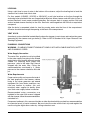
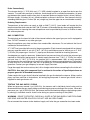
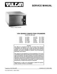
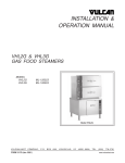
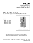
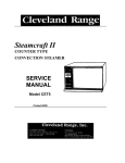
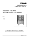
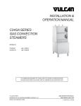
INSTALLATION &
OPERATION MANUAL
GAS CONVECTION STEAMERS MODELS
VSX5G, VSX5GC, VSX7GC & VSX10GC
MODELS
VSX 5G
VSX5GC
VSX7GC
VSX10GC
ML-114046
ML-114947
ML-114948
ML-114949
Model VSX10GC
For additional information on Vulcan-Hart Company or to locate an authorized
parts and service provider in your area, visit our website at www.vulcanhart.com
VULCAN-HART
COMPANY,
P.O.
BOX
696,
LOUISVILLE,
KY
40201-0696,
TEL.
(502)
778-2791
FORM 31051 Rev. B (Jan. 2003)
IMPORTANT FOR YOUR SAFETY
THIS MANUAL HAS BEEN PREPARED FOR PERSONNEL QUALIFIED TO INSTALL GAS
EQUIPMENT, WHO SHOULD PERFORM THE INITIAL FIELD STARTUP AND
ADJUSTMENTS OF THE EQUIPMENT COVERED BY THIS MANUAL.
POST IN A PROMINENT LOCATION THE INSTRUCTIONS TO BE FOLLOWED IN THE
EVENT THE SMELL OF GAS IS DETECTED. THIS INFORMATION CAN BE OBTAINED
FROM THE LOCAL GAS SUPPLIER.
IMPORTANT
IN THE EVENT A GAS ODOR IS DETECTED, SHUT DOWN
UNITS AT MAIN SHUTOFF VALVE AND CONTACT THE LOCAL
GAS COMPANY OR GAS SUPPLIER FOR SERVICE.
FOR YOUR SAFETY
DO NOT STORE OR USE GASOLINE OR OTHER FLAMMABLE
VAPORS OR LIQUIDS IN THE VICINITY OF THIS OR ANY
OTHER APPLIANCE.
WARNING: IMPROPER INSTALLATION, ADJUSTMENT,
ALTERATION, SERVICE OR MAINTENANCE CAN CAUSE
PROPERTY DAMAGE, INJURY OR DEATH. READ THE
INSTALLATION, OPERATING AND MAINTENANCE
INSTRUCTIONS THOROUGHLY BEFORE INSTALLING OR
SERVICING THIS EQUIPMENT.
IN THE EVENT OF A POWER FAILURE, DO NOT ATTEMPT TO
OPERATE THIS DEVICE.
© VULCAN-HART COMPANY, 2003
–2–
TABLE OF CONTENTS
GENERAL .............................................................................................................................................4
INSTALLATION ....................................................................................................................................4
Unpacking .......................................................................................................................................4
Installation Codes and Standards ..................................................................................................5
Location ...........................................................................................................................................5
Legs (Countertop Steamer—Model VSX5G only) ........................................................................5
Leveling ...........................................................................................................................................6
Vent Hood ........................................................................................................................................6
Plumbing Connections ....................................................................................................................6
Gas Connection ..............................................................................................................................7
Testing the Gas Supply Piping .......................................................................................................7
Electrical Connection ......................................................................................................................8
Electrical Data .................................................................................................................................8
Test Procedure ...............................................................................................................................9
OPERATION .......................................................................................................................................10
Controls .........................................................................................................................................10
Startup Procedure ......................................................................................................................... 11
Stand By ........................................................................................................................................11
Steaming ........................................................................................................................................11
Daily Shutdown Procedure ...........................................................................................................11
Procedure for Complete or Prolonged Shutdown .......................................................................11
Steam Cooking .............................................................................................................................. 12
Preparation ....................................................................................................................................12
Compartment Accommodation .....................................................................................................12
Cleaning .........................................................................................................................................13
MAINTENANCE ..................................................................................................................................15
Deliming .........................................................................................................................................15
Steam Unloader Ports .................................................................................................................. 15
Vent ................................................................................................................................................15
Service and Parts Information ...................................................................................................... 15
TROUBLESHOOTING .......................................................................................................................16
–3–
Installation, Operation and Care of
MODELS VSX5G, VSX5GC, VSX7GC & VSX10GC
GAS CONVECTION STEAMERS
SAVE THESE INSTRUCTIONS
GENERAL
The VSX5G, VSX5GC, VSX7GC and VSX10GC gas-fired convection steamers have one or two
pressureless steaming compartments for cooking vegetables, eggs and other foods. Each compartment
has a 0 to 60 minute timer (buzzer requires manual shutoff).
Steamers are for use in commercial kitchens only.
Accommodation and Gas Rating
Model
Compartments
Total Number of 2.5" Deep Pans
Gas Rating
VSX5G
1
5
45,000 BTU/hr
VSX5GC
1
5
45,000 BTU/hr
VSX7GC
2
7
90,000 BTU/hr
VSX10GC
2
10
90,000 BTU/hr
Model VSX5G is provided with a set of legs for installation on a suitable countertop. Models VSX5GC,
VSX7GC and VSX10GC are equipped with a cabinet base for floor installation.
INSTALLATION
UNPACKING
Immediately after unpacking, check for possible shipping damage. If the steamer is found to be
damaged, save the packaging material and contact the carrier within 15 days of delivery.
–4–
INSTALLATION CODES AND STANDARDS
In the United States, the steamer must be installed in accordance with:
1. State and local codes.
2. National Fuel Gas Code, ANSI-Z223.1 (latest edition), available from the American Gas Association,
1515 Wilson Boulevard, Arlington, VA 22209.
3. National Electrical Code, ANSI/NFPA No. 70 (latest edition), available from the National Fire
Protection Association, Batterymarch Park, Quincy, MA 02269.
4. NFPA Standard # 96 Vapor Removal from Cooking Equipment , latest edition, available from the
National Fire Protection Association, Batterymarch Park, Quincy, MA 02269.
In Canada, the steamer must be installed in accordance with:
1. Local codes.
2. Natural Gas and Propane Installation Code CSA B149.1 (latest edition).
LOCATION
Before installing, verify that the gas (natural or propane) and the electrical supply agree with the
specifications on the data plate.
The installation location must be kept free and clear of combustibles. Do not obstruct the flow of
combustion and ventilation air. Minimum clearances from noncombustible and combustible construction
are 8 inches (20 cm) on the right side, 3 inches (8 cm) on the left side, and 6 inches (15 cm) at the rear
for proper air circulation. The steamer should be installed on a noncombustible floor. Provide adequate
clearances for cleaning, maintenance, service and proper operation.
Sufficient air should be allowed to enter the room to compensate for the amount of air removed by any
ventilating system and for combustion of the gas burners. Do not obstruct the air flow into and around
the appliance. Do not obstruct the flow of flue gases from the flue duct located at the rear and above
the steamer. Position the steamer in its final location. Check that there are sufficient clearances to
service the controls, for door(s) to swing and to allow the required supply and drain connections.
Allow enough space between any other piece of equipment or a wall for service access. Service for
the controls for the steamer compartments requires access to the upper right side panel.
LEGS (Countertop Steamer—Model VSX5G only)
Install 4" legs by threading the stud into the holes provided underneath at four corners.
–5–
LEVELING
Using a spirit level or pan of water in the bottom of the steamer, adjust the leveling feet to level the
steamer front to back and side to side.
For floor models (VSX5GC, VSX7GC or VSX10GC), mark hole locations on the floor through the
anchoring holes provided in the rear flanged adjustable feet. Move steamer and drill holes in floor at
marked locations. Insert proper anchoring devices. Set steamer back in proper position. Bolt and
anchor leveled steamer securely to the floor. Seal bolts and flanged feet with Silastic or equivalent
compound.
After the drain is connected, check for level by pouring water onto the floor of the compartment.
All water should drain through the opening at the back of the compartment.
VENT HOOD
An exhaust system should be located directly above the steamer to vent steam and combustion gases
generated by the steamer and gas boiler(s). Refer to NFPA Standard # 96 Vapor Removal from
Cooking Equipment .
PLUMBING CONNECTIONS
WARNING: PLUMBING CONNECTIONS MUST COMPLY WITH APPLICABLE SANITARY, SAFETY
AND PLUMBING CODES.
Water Supply Connection
The water filter, provided, must be installed
in the water supply line going to the filtered
water inlet; or your steamer warranty may be
voided. For incoming water supply line
pressures, refer to the water filter manual
shipped with the water filter. Follow the
recommendations contained in it. Water
pressure to the steamer should be 20 to 60
psi.
Water Requirements
Proper water quality can improve the taste of
the food prepared in the steamer, reduce
liming in the steam generator and extend
equipment life. Local water conditions vary
from one location to another. Ask your
municipal water supplier for details about
your local water supply before installation.
Recommended water parameters are
included in the water filter manual shipped
with the steamer; follow the recommendations
contained in it.
Fig. 1
Presence of sediment, silica, excess chlorides or other dissolved solids may lead to a recommendation
for alternate form(s) of water treatment. Be sure to test the water with the test strip and register the
results using the registration card or by visiting vulcanhart.com.
–6–
Drain Connection(s)
The steamer drain(s) 1" IPS (33.4 mm) (11/4" NPS) should be piped to an open floor drain near the
steamer. To avoid back pressure in the drain, there should not be a solid drain connection. An open
gap between the steamer and the floor drain is required. Maximum length of drain is 6 feet (183 cm);
minimum length, 24 inches (61 cm). Minimize bends or elbows in drain line. Vent steamer drain by
extending the drain pipe 11 inches (28 cm) straight up (from the upper tee on two chamber models).
Draining Requirements
Temperatures in the boiler can reach as high as 240°F (116°C). Local codes will require that the
temperature of the drain water be 140°F (60°C) or lower. At the end of the day when purging the boilers,
some provision for lowering the water temperature must be provided by the user or installer to meet
this code requirement.
GAS CONNECTION
The data plate on the lower left side of the steamer indicates the type of gas your unit is equipped to
burn. DO NOT connect to any other gas type.
Keep the appliance area free and clear from combustible substances. Do not obstruct the flow of
combustion and ventilation air.
A 3/4" NPT line is provided at the rear for the gas connection. Each steamer is equipped with an internal
pressure regulator which is set at 3.5" W.C. (.87 kPa) manifold pressure for natural gas or 5" W.C.
(1.25 kPa) for propane gas. Use the 1/8" pipe tap on the burner manifold for checking pressure.
An adequate gas supply is necessary. Undersized or low-pressure lines will restrict the volume of gas
required for satisfactory performance. A steady supply pressure from 7" W.C. (1.75 kPa) for natural
gas and from 11" W.C. (2.75 kPa) for propane gas is recommended. With all units operating
simultaneously, the manifold pressure on all units should not show any appreciable drop. Fluctuations
of more than 25% on natural gas, and 10% on propane gas, will create problems and affect burner
operation. Contact your gas company for correct supply line sizes.
Purge the supply line to clean out any dust, dirt or foreign matter before connecting the line to the unit.
CAUTION: Use pipe joint compound that is resistant to the action of liquefied petroleum or
propane gases on all threaded connections.
Codes require that a gas shutoff valve be installed in the gas line before the steamer. Make sure the
pipes are clean and free of obstructions, dirt and piping compound. A manual gas shutoff valve is
supplied for each gas burner unit.
TESTING THE GAS SUPPLY PIPING
When test pressures exceed 1/2 psi (3.45 kPa), the steamer and its individual shutoff valve must be
disconnected from the gas supply piping system during any pressure testing of the system. When test
pressures are 1/2 psi (3.45 kPa) or less, the steamer must be isolated from the gas supply piping system
by closing its individual manual shutoff valve during any pressure testing of the system.
WARNING: PRIOR TO STARTUP, CHECK ALL JOINTS IN THE GAS SUPPLY LINE FOR LEAKS.
USE SOAP AND WATER SOLUTION. DO NOT USE AN OPEN FLAME.
Do not connect the steamer to the electrical supply until after the gas connection has been made.
–7–
ELECTRICAL CONNECTION
WARNING: THE STEAMER IS PROVIDED WITH A THREE-PRONG GROUNDING PLUG. THE
OUTLET TO WHICH THIS PLUG IS CONNECTED MUST BE PROPERLY GROUNDED. IF THE
RECEPTACLE IS NOT THE PROPER GROUNDING TYPE, CONTACT AN ELECTRICIAN. DO
NOT REMOVE THE GROUNDING PRONG FROM THE PLUG.
WARNING: DISCONNECT THE ELECTRICAL POWER TO THE MACHINE AND FOLLOW
LOCKOUT / TAGOUT PROCEDURES.
Refer to the data plate and the electrical diagram located on the inside surface of the right side panel.
ELECTRICAL DATA
Models
Volts/Hertz/Ph
Amps
Miminum Circuit Ampacity
Maximum Protective Device Amps
VSX5G
VSX5GC
VSX7GC
VSX10GC
120/60/1
1.5
15
–8–
TEST PROCEDURE
WARNING: THE STEAMER AND ITS PARTS ARE HOT. USE CARE WHEN OPERATING,
CLEANING OR SERVICING THE STEAMER. COMPARTMENTS CONTAIN LIVE STEAM. STAY
CLEAR WHEN OPENING DOOR(S).
Once the steamer is installed and all mechanical connections have been made, thoroughly test the
steamer before operation.
1. Check that proper water, drain, electrical and gas connections have been made.
2. Turn main power switch to ON. After approximately 19 minutes, the Ready Light should come on,
indicating that the water temperature has reached 205°F (97°C).
3. Check that the Ignition Light comes on and cycles ON and OFF.
4. When the Ready Light comes on, set the timer to the 5-minute position. With door open, observe
that no steam is entering the compartment and the Cooking Light is OFF.
5. Close compartment door. The Cooking Light should now be lit, and steam should be heard
entering the compartment after about 45 seconds.
6. Check the drain line to be sure that water from the cold water condenser is flowing through the
drain line.
7. Open compartment door and observe that steam supply to the chamber stops, the Ready Light
comes on and the Cooking Light goes off.
8. Close compartment door and let cooking cycle finish. When the timer returns to the "0" position,
a buzzer will sound, signalling the end of the cooking cycle. To silence the buzzer, turn the dial
timer to OFF.
9. Complete the above steps for each cooking compartment.
10. To shut the cooker down, turn the main Power Switch OFF and close the manual gas shutoff
valve(s). Leave the compartment doors slightly open to allow the inside to dry out.
–9–
OPERATION
WARNING: THE STEAMER AND ITS PARTS ARE HOT. USE CARE WHEN OPERATING,
CLEANING OR SERVICING THE STEAMER. COMPARTMENTS CONTAIN LIVE STEAM. STAY
CLEAR WHEN OPENING DOOR(S).
CONTROLS
Fig. 2
Main Power Switch
ON
— Boiler tank fills [requires 12 minutes], heats water in the boiler tank to
205°F (97°C) [requires 7 minutes more] and maintains this temperature.
OFF
— Boiler tank drains.
Ready Light
— Boiler temperature has reached 205°F (97°C); steamer is ready to start
a cooking cycle.
Cooking Light
— A cooking cycle is in progress.
Timer
— Allows you to set the cooking time (0 to 60 minutes); steam cooking
begins when the door is closed. Steaming stops if the door is opened
during the cooking cycle; resume cooking by closing the door.
When the timed cycle is finished, a buzzer sounds, and steam stops
flowing into the compartment. Turn timer to OFF to stop the buzzer.
Ignition Light
— Boiler tank has filled, burner has ignited and tank water is heating.
NOTE: If the Ignition Light fails to remain on until the Ready Light comes on or the gas supply is
interrupted, a 5-minute period of complete shutoff is required before restarting.
– 10 –
STARTUP PROCEDURE
Open gas supply and make sure that the steamer door(s) are closed.
Turn Power Switch to the ON position. After unit fills with water, the Ignition Light will come on. If Ignition
Light fails to remain on until the Ready Light comes on or the gas supply is interrupted, a 5-minute period
of complete shutoff is required before restarting.
Ignition must be complete in 8.5 seconds, or the boiler control goes into lockout and power must be shut
off and turned back on to restart ignition.
STAND BY
Set Timer to OFF position and leave door slightly open.
STEAMING
Each steaming compartment is controlled by its own controls.
With the Ready Light lit, the steamer is ready for use.
•
Place pans of food to be cooked into compartment and shut door.
•
Set timer to the desired cooking time. Steaming begins.
•
The cooking cycle may be interrupted at any time by opening the compartment door; resume
cooking by closing the door.
•
When the buzzer sounds, the timed steaming cycle has finished. Steaming stops, the
COOKING light goes off and the Ready Light comes on. To silence the buzzer, turn the Timer
OFF.
DAILY SHUTDOWN PROCEDURE
Turn Power Switch to OFF; close manual gas shutoff valve.
NOTE: On steamers with two compartments (i.e., models VSX7GC and VSX10GC), each compartment
has its own boiler. Each compartment must be shut down.
PROCEDURE FOR COMPLETE OR PROLONGED SHUTDOWN
Turn Timer and Power Switch to OFF; boiler will drain.
Close manual water valve(s) and manual gas shutoff valve(s).
Disconnect power cord.
NOTE: On steamers with two compartments (i.e., models VSX7GC and VSX10GC), each compartment
has its own boiler. Each compartment must be shut down.
– 11 –
STEAM COOKING
The steamer efficiently cooks vegetables or other foods for immediate serving. Steam cooking should
be carefully time controlled. Keep holding time of hot food to a minimum to produce the most appetizing
results. Prepare small batches, cook only enough to start serving and then cook additional amounts
to meet demand. Separate frozen foods into smaller pieces to allow more efficient cooking.
Use a pan cover for recooked frozen dishes that cannot be cooked in the covered containers in which
they are packed if they require more than 15 minutes of cooking time. When a cover is used,
approximately one-third additional time is necessary.
Cooking time for frozen foods depends on amount of defrosting required. If time permits, allow frozen
foods to partially thaw overnight in a refrigerator. This will reduce their cooking time.
PREPARATION
Prepare vegetables, fruits, meats, seafood and poultry normally by cleaning, separating, cutting,
removing stems, pealing, etc. Cook root vegetables in a perforated pan unless juices are being saved.
Liquids can be collected in a solid 12" x 20" pan placed under a perforated pan. Perforated pans are
used for frankfurters, weiners and similar items when juices do not need to be preserved. Solid pans
are good for cooking puddings, rice and hot breakfast cereals. Vegetables and fruits are cooked in solid
pans in their own juices. Meats and poultry are cooked in solid pans in their own juices. Meats and
poultry are cooked in solid pans to preserve their own juices or to retain broth. Canned foods can be
heated in their opened cans (cans placed in 12" x 20" solid pans), or the contents may be poured into
solid pans. DO NOT place unopened cans in the steamer.
COMPARTMENT ACCOMMODATION
Steamers are designed to accept combinations of 12" x 20" pans (solid or perforated).
– 12 –
CLEANING
WARNING: DISCONNECT THE ELECTRICAL POWER TO THE MACHINE AND FOLLOW
LOCKOUT / TAGOUT PROCEDURES.
At the end of each day, or between cooking cycles if necessary:
•
Turn main power switch OFF.
•
Remove pans and racks from compartment and wash in sink.
•
Wash compartment interior with clean water. Never use steel wool or abrasive scouring pads
as they will scratch and ruin the general surface appearance of the steamer.
•
Use warm soapy water with a cloth or sponge to clean the exposed bead of the door gasket.
Rinse with warm clear water and wipe dry with a dry cloth.
•
Wipe surfaces which touch the door gasket with a cloth or sponge and warm soapy water. Rinse
with warm clear water and wipe with a dry cloth.
CAUTION: Do not allow the door gasket to come in contact with food oils, petroleum
solvents or lubricants.
•
Wipe all solids away from the drain openings in the compartments to prevent clogging.
•
Keep the cooking compartment drain working freely.
•
After cooking grease-producing foods, operate steamer with compartments empty for 30
minutes at the end of the day; or pour 1/2 gallon (2 liters) of warm soapy water down the drain,
followed by 1/2 gallon (2 liters) of warm clear water.
•
Leave the door slightly open when the steamer is not in use to allow the inside to dry out.
– 13 –
Weekly (More Often if Needed)
Clean exterior with a damp cloth and polish with a soft dry cloth. Use a nonabrasive cleaner to remove
discolorations.
Corrosive cleaning agents such as chlorides, acids, salts or vinegar may cause pitting and corrosion,
which will reduce the life of the appliance. Never spray water into electric controls.
Climatic conditions (salt air) may require more thorough and frequent cleaning, or the life of the
appliance may be adversely affected.
For hard-to-remove stains: Apply cleanser on a damp cloth or sponge and gently rub metal in the
direction of the polish lines. Avoid marring the stainless steel. Do not rub in a circular motion.
If the previous procedure fails, Scotch-Brite or stainless steel wool pads may be used. Do not use
ordinary steel wool because particles left on the surface will rust and spoil the finish. Never use a wire
brush, steel scraper, putty knife, file, steel wool pads (except stainless steel) or other steel tools.
Marring the surface will make it more difficult to clean and will increase the possibility of corrosive
attack.
Heat tint (a darkened area on stainless steel which was subjected to excessive heat) is not harmful but
can usually be removed by vigorous scouring in the direction of the polish lines using Scotch-Brite
scouring pads or a stainless steel wool combined with a moist paste of powdered cleanser.
– 14 –
MAINTENANCE
WARNING: THE STEAMER AND ITS PARTS ARE HOT. USE CARE WHEN OPERATING,
CLEANING OR SERVICING THE STEAMER.
WARNING: DISCONNECT THE ELECTRICAL POWER TO THE MACHINE AND FOLLOW
LOCKOUT / TAGOUT PROCEDURES.
DELIMING
Refer to the water filter manual shipped in the box with your steamer.
STEAM UNLOADER PORTS
Your steamer is equipped with 5 psi steam unloader ports at the rear of the steamer. If steam pressure
reaches 5 psi or more, steam will be exhausted through these ports. This pressure may be caused by
clogged cooking cavity steam ports, clogged steam tubing from the generator to the cooking cavity,
clogged drain plumbing or a blocked cooking cavity drain. Check and clear the cooking cavity drain.
If steam is still exiting the steam unloader ports, contact your local Vulcan-authorized servicer.
VENT
Twice a year, check the vent, remove any obstructions and clean as necessary.
SERVICE AND PARTS INFORMATION
For any repairs or adjustments needed on this equipment, contact the Vulcan-Hart-authorized service
agency in your area or Vulcan-Hart Service Department at the address or phone number on the front
cover of this manual.
– 15 –
TROUBLESHOOTING
WARNING: THE STEAMER AND ITS PARTS ARE HOT. USE CARE WHEN OPERATING,
CLEANING OR SERVICING THE STEAMER.
Symptom
Possible Cause
Burner does not come on.
Gas supply is off, power cord is unplugged or switch is off.
Burner control goes into 100% lockout. If symptom persists,
contact Service.
Boiler dirty (carbon black).
Contact Service.
Water flows into compartment.
Delime. If symptom persists, contact Service.
Door leaks.
Check door gasket for damage. If adjustment is needed,
contact Service.
Water accumulates in compartment.
Drain clogged.
Water not being supplied to boiler.
Water supply valve is off. Check water supply pressure.
If symptom persists, contact Service.
Water flows into drain when unit is off.
Contact Service.
FORM 31051 Rev. B (Jan. 2003)
– 16 –
PRINTED IN U.S.A.