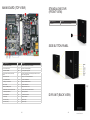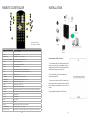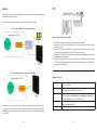
1
APEC CCTV
TVR 3000 Series
Embedded DVR
USERS
MANUAL
TABLE OF CONTENTS
GETTING STARTED
What is a Digital Video Recorder (DVR)?
INSTALLATION AND SAFEGUARDS
Environment Condition for Installation
Before You Start
SUMMARY OF FEATURES SPECIFICATION AND MODEL PACKAGE CONTENTS
Internal Unit of Wall-mount Case
Main Board (Top View) Standalone DVR (Front View)
Side Button Panel
DVR Unit (Back View)
Remote Controller
5
5
6
6
6
7
9
10
11
12
13
13
13
14
INSTALLATION
HDD
Cameras
Sensors
Relays
Network
PTZ
15
16
16
17
17
18
19
LIVE VIEW
Display Components
Main Menu
On-Screen Keyboard
Camera Layout
Cycle Camera
Picture-In-Picture (PIP)
Digital Zoom
Display Freeze
Image Enhance
Manual / Forced Recording
Live Audio
Relay Control
PTZ Control
20
20
21
21
22
22
23
23
24
24
25
25
26
27
SEARCH AND PLAYBACK
Event Search
Smart Search
28
29
29
SETUP MODE
Login
System
Information
Date and Time
Network
TCP/IP Setting
DDNS
User
OSD
Tools
Recording
Camera
Frame Rate
Resolution
Audio
Schedule
Watermark
Event
Notification
Sensor
Relay
Motion
Mappings
Sensor to Camera
Sensor to PTZ
Camera to Relay
Sensor to Relay
Video Lost to Relay
PTZ
Comm Settings
Camera
PTZ Speed
Presets
Language
30
30
31
32
32
34
35
37
37
38
40
42
42
43
44
45
45
47
47
48
49
50
50
51
52
52
53
53
54
55
55
56
56
57
57
BACKUP MODE
Video Backup
Image Backup
58
58
59
REMOTE VIEW
Client Login
DVR Connection
Remote Client OSD
Digital Zoom
Video Event Log
Date and Time
Image Control
Screen Capture
Forced Recording
Sensors
Relays
Audio
PTZ Function
Presets
Pattern Tracking
Group Run
60
61
61
62
62
63
63
64
64
64
65
65
65
66
66
67
67
SEARCH & PLAYBACK
Playback Recordings
68
69
CLIENT SETUP
DVRs
Groups
Users
System
Display
70
70
71
71
72
73
REMOTE SERVER SETUP
Setup Menu Options
Camera Setup
Audio
Sensor Mapping
Sensor PTZ Mapping
Motion Mapping
Relay Reset Mode
Alarm Notification
PTZ Settings
Recording Schedule
System Settings
Network
Users
74
74
75
76
77
78
79
80
81
82
83
84
85
86
GETTING STARTED
What is a Digital Video Recorder (DVR)?
DVR stands for digital video recorder. Digital video recorders run on computers and are equipped with
one or more video capture cards, that record and compress video (and/or audio) to a hard-drive based
storage medium.
Reliability
Digital security solutions offer reliability because these solutions are based on computer hardware and software. Digital security solutions require fewer pieces working together compared to
old VCRs, thus making it less prone to wear and tear. Video can be also stored directly onto hard
drives without much hassle.
Reduced Maintenance Costs
Digital security hardware is designed as a self-contained unit, eliminating the need for quads,
switchers, multiplexers, time-lapse VCRs, motion detectors and remote monitoring devices. With
fewer pieces needed to work together, it enables such digital solutions to be supported and maintained by less people. Digital security solutions also allow most diagnostics, updates and adjustments to be done remotely, thus reducing overall costs.
Constant Quality
Digital security solutions are very stable and reliable as a medium for video storage. You wouldn’t
have to worry about video quality degradation.
More Efficient
With digital security solutions, you do not need to change and replace tapes. You do not need
to clean recording heads to ensure correct recording. Digital security solutions saves you time and
money, because you can overcome serious problems associated with failing to carry out some of
the tasks you need to do for legacy systems. Moreover, while quads and switchers make recording multiple cameras possible, cameras are recorded one at a time in timed segments. With digital
security solutions, you can record all cameras simultaneously.
Flexible Network Monitoring
Network cameras offer remote monitoring from anywhere in the world. Because you can monitor from anywhere, you need not hire a permanent in-house staff to sit and watch at the installed
base. You also eliminate costly in-house cable runs. Digital security solutions also offer centralized
monitoring of all cameras.
INSTALLATION AND SAFEGUARDS
SUMMARY OF FEATURES
All the safety and operating instructions should be read before the unit is operated.
Live View
1. Real-time Display per Camera: 30fps NTSC / 25fps PAL per channel
2. Different View Layouts: 1 or full screen, 2, 4, 9, 16
3. Cycle Cameras: View cameras/channels in sequence
4. Picture-in-Picture: Display camera/channel view on top of another camera/channel
5. Digital Zoom: Up to 9x digital zoom
6. Display Freeze
7. On-screen Status
8. Image Enhance: Adjust brightness, contrast, hue and saturation
9. Manual / Forced Recording: Manually start recording
10. Live Audio
11. Sensor Status and Relay Control: Display sensor status and toggle relay
12. PTZ Control: Presets, Zoom, Focus, Iris Settings and Auto Pan
Environment Condition for Installation
To prevent electric shock or other hazards, do not expose units to rain, moisture or dust.
This unit should be located in an area with low humidity and minimum dust.
Place this unit in a well-ventilated place and do not place heat-generating objects on this unit.
This unit should not be located in an area where it is likely to be subjected to mechanical shocks.
Before You Start
This unit should be operated only from the type of power source indicated on the manufacturer’s label.
Notes
1.
2.
3.
4.
5.
6.
Be aware thoroughly about the power connection before installation of the unit.
Repairs should be referred to the supplier or to the manufacturer.
There are sensitive parts in the equipment. Do not dismantle the equipment.
Power cord should be arranged safely. Do not touch power cord with wet hands.
Do not use loose plug or damaged power cable.
Do not use benzene, thinner or alcohol for cleaning the product. It could damage the
product.
7. Do not touch exposed terminals.
8. To switch off the system, simply unplug power cord from socket, and then switch off the peripheral equipment.
9. When smoke is seen coming from the equipment, immediately unplug the power cord from power source to prevent fire or electric shock.
Recording
1. Variable Resolution: CIF, ½ D1 and D1
2. Variable Image Quality: Low, Medium, High
3. Variable Recording Modes: Continuous, Motion, Sensor and Event
4. Automatic Disk Storage Management
5. Audio Recording
Search and Playback
1. Event Search: Search by year, month, day, hour, event type and camera number
2. Smart Search: Search with timeline display, filter by event type and camera number
3. Single or Multi-channel Playback
4. Variable Playback Speed: 2x, 4x, 8x, 16x, 1/2x, 1/4x, 1/8x, 1/16x
Setup
1. System
2. Information: Display hardware and software information
3. Date and Time: Set date and time
4. Network: Set network configuration
5. DDNS: Set DDNS configuration
6. User: Set password for user
7. OSD: Set On-Screen Display (OSD) settings
8. Tools: Hard disk utilities, Video Signal and DVR Server Updater
9. Recording
10. Camera: Set camera status and video quality
11. Frame Rate: Set normal and event frame rate
12. Resolution: Set normal and event resolution
13. Audio: Set audio status and input gain
14. Schedule: Set recording schedule
15. Watermark: Enable/Disable watermark
SPECIFICATION AND MODEL
cont... Summary of Features
16. Event
17. Notification: Red Border and Email
18. Sensor: Set sensor status
19. Relay: Set relay reset mode as manual, time-based or synchronized
20. Motion: Set area for motion detection
21. Mappings:
22. Sensor to Camera
23. Sensor to PTZ Camera
24. Camera to Relay
25. Sensor to Relay
26. PTZ
27. Communication Settings: Baud Rate, Data Bit, Parity and Stop Bit
28. Camera: Set PTZ Camera Status and Protocol
29. Speed: Pan/Tilt speed, Zoom speed and Focus speed
30. Presets
31. Language
4 channel
HDD
Inputs
Composite
Outputs
TV Out
up to 2 HDDs
up to 2 HDDs
4 ch BNC
8 ch BNC
1 ch TV Out
Compression
Compression Rate
8 channel
Hardware MPEG4
Default
Display Speed
Search
Recording Mode
2-9 Kb per frame (CIF @
2-9 Kb per frame (CIF @
360x240)
360x240)
120/100fps
240/200fps
Event Search and Smart
Event Search and Smart
Search
Search
Continuous, Scheduled,
Continuous, Scheduled,
Motion-Detected, Event-Trig-
Motion-Detected, Event-
gered (Motion and Sensor-
Triggered (Motion and
Triggered), Sensor-Triggered
Sensor-Triggered), SensorTriggered
Backup
Via USB external storage or network
Remote Client (Software included)
1. Remote Surveillance
2.Client Setup: Add/Edit DVR Server Connection, User settings and System settings
3.DVR List
4.Video Event Logs
5.Different View Layouts: 1 or full screen, 4, 9, 16
6.PTZ Control
7.Sensor/Relay/Audio Control
8.Image Enhance
9. Snapshot or Screen Capture
10.Remote Search and Playback
11.1 channel Forced recording
12.Remote Setup
360x240 120fps
360x240 240fps
720x240 120fps
720x240 240fps
720x480 60fps
720x480 120fps
360x288 100fps
360x288 200fps
720x288 100fps
720x288 200fps
720x576 50fps
720x576 100fps
NTSC
720x480, 720x240, 360x240
720x480,720x240, 360x240
PAL
720x576, 720x288, 360x288
720x576,720x288, 360x288
Live View
Output Modes
1, 2, 4
1, 2, 4, 9
Playback
Playback Speed
120/100fps
240/200fps
Ethernet (TCP/IP)
Ethernet (TCP/IP)
10/100 Base T
10/100 Base T
Network
Backup
via USB
PTZ Control
RS-485
Web View
1.Real-time Streaming Video
2. Event notification
Audio
Back up Viewer (Software Included)
Sensor Inputs
4 ch
Relay Outputs
2 ch
Watermark
Yes
Watchdog
Yes
Inputs
4 ch
Outputs
Compression
Hardware G.723.1
* Specification subject to change without prior notice.
8 ch
1 ch
PACKAGE CONTENTS
Internal Unit of Wall-mount Case
DVR – Internal Unit
Description
1. Main Switch
To on/off the DVR unit
2. Hard Disk Bracket
Holds the hard disks
3. Hard Disk Drives
DVR storage device
4. Fan
For DVR ventilation
5. IDE cable
Connects the HDD to the main board
Standalone Digital Video Recorder
6. Video Output
Video out terminal
2. Remote Controller
DVR Remote Controller
7. Speaker Out
Audio out terminal
3. AC Power Cord
Power cord (220/110V)
8. Input voltage
Supplies voltage
4. Hard Disk screws
8 pcs screws for putting the hard disk in place
9. DB25
Audio/Video input terminal
5. IDE Cable
IDE cable for hard disk
10. Power cable
For power supply
6. Audio Video Cable (DB25)
Connection for Camera and Audio
Package Contents
1. DVR Main Unit
Description
7. Keys
To lock/unlock the DVR cover
8. Hardcopy of user’s manual
TVR-3000 User’s Manual
10
11
Main Board (Top View)
Standalone DVR
(Front View)
DVR – External Unit
Description
1. IR Sensor
Infrared Sensor for Remote Controller
Side Button Panel
DVR – Internal Unit
Ref. Des.
Description
1. 4-Pin ATX Power Connector
J17
2 40-Pin IDE Connector
J10
Connection to hard disk (HDD1)
3. Tact Switch “RESET”
SW1
For resetting/rebooting system
4. Terminal Block “Sensor Input & Relay
Output”
Connection to power supply 12V-5V-GND
J1
Connecting Sensor devices and Relay Output devices to control
sensors and trigger alarms
5. Ethernet Connector
J3
Where you can connect the RJ45 cable
6. 2 pc. USB Connector
J16
Connection to USB device
7. Debug1 or uart Connector
B1
RS232 port for GSM connection
8. IR connector
J6
Connection to IR sensor
9. Battery and Battery holder
J7
Battery for Real Time Clock
10. DB25 Video and Audio Input Connector
J3
Connection with CCTV Camera and Audio
11. Audio Output RCA Jack
P3
Audio Output terminal
12. TV Out RCA Jack
P2
1 TV Out RCA connection
13. Audio Input
J5
Audio Input Terminal
14. 8 sensor, 4 relay
J6
Input and output
15. 8 sensor, 4 relay
J7
Input and output
12
DVR Unit (Back View)
13
Remote Controller
INSTALLATION
*For the remote control,
use 1 lithium ion 3V battery
DVR – External Unit
Description
1. Live
Switch to Live View Mode
2. Setup
Switch to Setup Mode
3. ENTER / Cycle
Save settings or Go to / Cycle cameras
4. Up / Down / Left / Right Arrows
Move up / Move down / Move left / Move right
5. Record
Start/Stop FORCED recording
6. Search
Search and playback recorded video
7. Backup
Switch to Backup Mode
8. Focus
For increasing/decreasing focus *For PTZ camera only
9. Iris
For increasing/decreasing brightness *For PTZ camera only
10. Zoom
For zooming in or out
11. Speed Up
To increase playback speed 2x, 4x, 8x or 16x
12. Speed Down
To decrease playback speed 1/2x, 1/4x, 1/8x, 1/16x
13. Play / Freeze
Play video / Freeze or pause video
14. Next
Go to next frame (frame by frame)
15. Previous
Go to previous frame (frame by frame)
16. Forward
Forward playback of video files 10 seconds; also used in search to move 5 hours/minutes up
17. Rewind
Rewind playback of video files 10 seconds; also used in search to move 5 hours/minutes down
18. Audio
Enter Audio Mode
19. Relay
Enter Relay Mode
20. PIP
Picture in Picture
21. PTZ
Enter PTZ
22. Display
Adjust image brightness, contrast, hue and saturation
23. Number Buttons
Go to camera number (1), (2) … and so on
24. Number 10 button
Also functions as a “0” button when used as a single digit in passwords, labels, ip address, etc.
14
How to install the DVR on the wall:
1. For cemented walls, use a drilling machine to drill
screws on the wall. Follow the diagram beside for
drilling positions. (NOTE: If possible, please measure
the distances of screw holes in your unit.)
2. For wooden walls, you may use a hammer to
initially puncture the wall.
3. Insert screws and fasten DVR unit when done.
Ensure that the unit is carefully mounted on the wall
before attaching other peripherals. Use at least 1in
screws.
The approximate net weight of the DVR is 5kg.
15
Sensors
HDD
How to Install the HDD:
How to Connect Sensors to the DVR:
1. Place HDD1 to the left side of the
bracket and connect it using the screws.
Note: The jumper setting of your HDD1
should be on Slave.
1. Connect sensors to Sensor Inputs, marked S1 to S4 and Ground.
2. To connect sensors, simply insert the wire inside the connector hole and push the connector button
to lock the wire.
2. Place HDD2 to the right side of the
bracket and connect it using the screws.
Note: The jumper setting of your HDD2
should be on Master.
3. Place the HDD bracket inside the DVR
unit.
4. Attach the left side of the bracket to the
DVR chassis using the screws.
5. Attach the right side of the bracket to
the DVR chassis using the screws.
6. Connect the IDE cable to HDD1 and
HDD2.
7. Connect the power cable to HDD1 and HDD2.
Cameras
Relays
How to Connect Cameras to the DVR:
How to Connect Sensors to the DVR:
1. Connect cameras to DB25 cable’s Video
Inputs, labeled CAM1 to CAM8.
2. Connect the DB25 cable to the unit’s DB25
Video and Audio Input Connector.
1. Connect relays to the Relay Outputs, marked R1, R2 and Common.
2. To connect relays, simply insert the wire inside the connector hole and push the connector button to
lock the wire.
16
17
Network
PTZ
Please call your service provider to identify which type of service they’re providing to determine which
type of network scenario you will use.
Once you have determined which scenario to use, connect your DVR unit as shown.
Case A: Single or Multiple Static IP w/ Personal Router
How to connect PTZ Cameras to the DVR:
1. Check if the PTZ camera is connected to a power source to enable operation.
2. Connect your PTZ camera to the DVR’s Video Input. You will see the video in your DVR as soon as
this connection is done.
3. Connect your PTZ camera to the RS-485 port. Connection to RS-485 port may be accompanied by
an interface converter, depending on the type of PTZ camera you are using.
4. If you are using an interface converter, ensure that this device (interface converter) is connected to
a power source to enable operation.
5. Enter the DVR’s Setup and go to PTZ Setup. Under PTZ setup, you will have to define which camera
is a PTZ camera and what protocol your PTZ camera is using. Please refer to your PTZ camera’s
manual for the latter information.
Case B: Single Static IP Directly Connected to the DVR
Naming Conventions
Ensure that you verify Internet access after installing any new equipment (routers, hubs, modems, etc.).
If possible, use a PC on a network to verify that an Internet connection can be made and that all current
configurations on any equipment are up and running smoothly. Do this before doing ANY configurations
with your DVR.
18
[BUTTON]
Text enclosed in square brackets refer to a button either on the remote controller
or on the control panel.
MODE
Capitalized text refer to a mode of the DVR. Some examples are LIVE VIEW,
SEARCH, SETUP, BACKUP, RELAY and AUDIO.
Menu
Bold text refer to an item appearing in a selection menu or the selection menu
itself. Some examples are Main Menu, Camera, Mappings and Tools. Note
that MODEs may appear as items in a selection menu
Component
Italicized text refer to important components or features in the DVR that help
users in interacting with the DVR.
KEYS
Text in this font refer to keys on the On-Screen Keyboard.
19
LIVE VIEW
Main Menu
Display Components
The Main Menu is the primary access point for many of the
DVR features. In LIVE VIEW, the Main Menu will be displayed
when [MODE] is pressed on the Control Panel.
Below are the components for Live View.
Note that all of the above functions have equivalent buttons on
the remote controller. Hence, when using the remote controller,
the Main Menu is not needed.
Use [UP] and [DOWN] buttons on the control panel to navigate
through the Main Menu. Use [SELECT] to make a selection.
On-Screen Keyboard
Upon startup, the DVR is in LIVE VIEW. If you are in another mode such as SETUP or SEARCH, press
[LIVE] to go back to LIVE VIEW.
The On-Screen Keyboard appears automatically when there is a need to type alphanumeric characters
on the screen.
Standard Display and Icon
1.
2.
3.
4.
You can move around the On-Screen Keyboard using [LEFT], [RIGHT], [UP] or [DOWN] buttons on the
remote controller or control panel.
Date
Time
Live view mode (or current mode)
Camera label
You can select a character or control on the On-Screen Keyboard using [ENTER] on the remote
controller or [SELECT] on the control panel.
There are special keys on the On-Screen Keyboard:
3 - Cursor Keys move the cursor
4 - DEL deletes the current character
5 - ENTER or SELECT exits the On-Screen Keyboard and returns the characters typed in.
20
21
Picture-In-Picture (PIP)
Camera Layout
Procedure Using Remote Controller:
1. When in Full Screen display, you may press
on [PIP] to view another channel in a smaller
window.
2. Press [1], [2], or [3] … to view camera 1, 2 or
3 in a smaller window.
3. Press [UP], [DOWN], [LEFT] or [RIGHT] to
move the smaller window.
4. To exit PIP, just press [PIP] again.
The PIP function is available only on the remote controller. Although, the [UP], [DOWN], [LEFT] and
[RIGHT] buttons on the control panel will be functional once the DVR is in PIP mode.
Digital Zoom
Cycle Camera
Procedure Using the Remote Controller:
1. In Full Screen, press ZOOM [+] to get a closer
view of the subject or to zoom in.
2. While zoomed in, press [UP], [DOWN], [LEFT],
or [RIGHT] to change the view of the zoomed in
area.
3. Press ZOOM [-] to zoom out.
Procedure Using the Control Panel:
Procedure Using the Remote Controller or Control Panel:
1. In LIVE VIEW, press [MODE].
2. Select Zoom by pressing [UP]/[DOWN] and [SELECT].
3. While zoomed in, press [UP], [DOWN], [LEFT], or [RIGHT] to change the view of the zoomed in
area.
4. Press [BACK] to zoom out and go back to LIVE VIEW.
1. To view in sequence or to view slide show of the channels in Full Screen, press [CYCLE] on the
remote controller or [SELECT] on the control panel. Channel view changes every three (3) seconds by
default.
2. To exit, press on [CYCLE] or [SELECT] again.
3. To configure cycle delay time, please go to SETUP.
22
23
Display Freeze
Manual / Forced Recording
Procedure Using the Remote Controller:
Procedure Using the Remote Controller:
1. Press [FREEZE] to pause display.
2. To exit, press on [FREEZE] again.
Press [RECORD] to start manual or forced
recording. Press [RECORD] again to exit or
stop recording.
This function is available only on the remote
controller.
Procedure Using the Control Panel:
1. In LIVE VIEW, press [MODE].
2. Select Forced Recording by pressing [SELECT]. This will bring you back to LIVE VIEW. The Forced
Recording icon will indicate that the DVR is currently on forced recording mode.
3. In LIVE VIEW mode, press [BACK] to stop recording. In other modes such as SETUP or SEARCH,
pressing [BACK] will not stop the recording.
Image Enhance
Live Audio
Procedure Using the Remote Controller:
Image enhancement capabilities include ability to control Brightness, Contrast, Saturation and Hue of
each camera. Recording (or recorded videos) will be affected by these settings.
Procedure Using the Remote Controller:
1. Press [DISPLAY] to adjust Brightness, Contrast, Saturation and Hue.
2. Press [UP] or [DOWN] to select image enhancement option.
3. Press [LEFT], [RIGHT], [+] or [-] to increase or decrease values.
4. Press [ENTER] to save settings and go back to Live View. Or, press [DISPLAY] to exit, without saving
changes.
Procedure Using the Control Panel:
1. Press [AUDIO] to modify audio settings. Press on [LEFT], [RIGHT], [+] or [-] to increase or decrease
output volume.
2. Press [1], [2], [3], … or [ENTER] to select audio channel.
3. Press [AUDIO] again to exit.
4. Press on [FREEZE] to mute output volume.
Procedure Using the Control Panel:
1. In LIVE VIEW, press [MODE].
2. Select Audio by pressing [UP]/[DOWN] then [SELECT].
3. Press on [LEFT] or [RIGHT] to increase or decrease output volume.
4. Press [SELECT] repeatedly to switch audio channels.
5. Press [BACK] to go back to LIVE VIEW.
1. In LIVE VIEW, press [MODE].
2. Select Display by pressing [UP]/[DOWN] and [SELECT].
3. Press [UP] or [DOWN] to select image enhancement option.
3. Press [LEFT] or [RIGHT] to increase or decrease value for that particular option. 4. Press [SELECT]
to save settings and go back to LIVE VIEW.
5. Press [BACK] to exit without saving changes.
NOTE: Values are displayed on the right, indicated from numbers 1-25. The default value for all images enhance
options is 12.
24
25
Relay Control
PTZ Control
Relay Control is used to manually toggle relays as ON or OFF. A red-colored relay is ON. A transparent
relay is OFF. A relay with a heavy border is the currently selected relay.
To use PTZ Control, ensure that your camera is a PTZ (Pan/Tilt/Zoom) camera.
An alert stating, NOT A PTZ CAMERA will display when you try to use PTZ Control for non-PTZ
cameras.
Procedure Using Remote Controller:
Procedure Using the Remote Controller:
1. Press [RELAY].
2. Press [LEFT], [RIGHT], [+] or [-] to select username.
3. Press [DOWN] to move to the password field. Use the numeric keys to enter the password then press
[ENTER].
4. Press [1], [2], [3]… to toggle relay 1, 2 (and so on) as ON or OFF. Alternatively, press [LEFT] or
[RIGHT] to select a relay, then press [ENTER] to toggle the status of the relay.
5. Press [RELAY] again or [LIVE] to go back to LIVE VIEW.
1. Press [PTZ] to enter PTZ Control.
2. Press [UP], [DOWN], [LEFT] or [RIGHT] to control the direction of the PTZ camera.
3. Press ZOOM [+] or [-] to zoom in or out.
4. Press FOCUS [+] or [-] to adjust focus.
5. Press IRIS [+] or [-] to adjust amount of light captured by the camera.
6. Press [PTZ] again to exit.
Procedure Using the Control Panel:
Procedure Using Control Panel:
1. In LIVE VIEW, press [MODE].
2. Select Relay by pressing [UP]/[DOWN] then [SELECT].
3. Select username by pressing [LEFT/RIGHT].
4. Press [DOWN] to move to the password field. Use the on-screen keyboard to type the password.
5. Press [LEFT] or [RIGHT] to select a relay, then press [SELECT] to toggle the status of the relay.
6. Press [BACK] to go back to LIVE VIEW.
26
1. In LIVE VIEW, press [MODE].
2. Select PTZ by pressing [UP]/[DOWN] then [SELECT].
3. Press [UP], [DOWN], [LEFT] or [RIGHT] to control the direction of the PTZ camera.
3. Press [SELECT] to change the function of [UP] and [DOWN] to zoom in or out, and the function of
[LEFT] and [RIGHT] to focus in or out. Iris control is not supported by the Control Panel.
5. Press [SELECT] again to change the function of [UP], [DOWN], [LEFT] and [RIGHT] to pan/tilt.
6. Press [BACK] to go back to LIVE VIEW.
27
SEARCH AND PLAYBACK
Event Search
Procedure Using the Remote Controller or Control Panel:
1. Under SEARCH and PLAYBACK, select Event Search by pressing on [ENTER] or
[SELECT].
2. Under Event Search, press [UP] or
[DOWN] to select option that you want to
change. For instance, if you want to edit
day, simply press [DOWN] until you highlight the Day option.
3. Press [LEFT], [RIGHT], [+] or [-] to change
the values of the given option.
4. Press [ENTER] or [SELECT] to run search.
If there are no recorded videos, repeat
steps 2 to 5. You will then be taken to a screen, displaying your search results.
5. Select the video that you want to playback by pressing [UP] or [DOWN] and press [ENTER] or
[SELECT] to view recorded video.
6. Press [LEFT] or [RIGHT] to move from previous or next pages.
NOTE: Up to a maximum of 10 recorded videos will be displayed per page.
Smart Search
SEARCH and PLAYBACK can be used for thorough look-up and playback of any recorded video.
Procedure Using the Remote Controller:
1. Press [SEARCH] to activate Search and Playback mode.
2. Press [UP] or [DOWN] to choose between Event Search or Smart Search.
3. Press [ENTER] to go to the selected option.
Procedure Using the Control Panel:
1. In LIVE VIEW, press [MODE].
2. Select Search by pressing [UP]/[DOWN] then [SELECT].
3. Press [UP] or [DOWN] to choose between Event Search and Smart Search.
4. Press [SELECT] to go to the selected option.
28
Legend:
1. Red – indicates that there is an event on
the specific field
2. White – indicates current selected field or
current selection
3. Blue – indicates cursor pointer position
Procedure Using the Remote Controller or
Control Panel:
1. Under Smart Search, press on [LEFT], [RIGHT], [+] or [-] to select camera, and then press [DOWN].
2. Use [LEFT], [RIGHT], [+] or [-] to select event type. You may choose from ALL, FORCED, SENSOR,
MOTION, AUDIO, EVENT or CONTINUOUS. Then, press [DOWN].
3. Select week by pressing [LEFT] or [RIGHT]. If you see red markings, that means there are recordings
on that particular period. Then press [DOWN] to go to next options.
4. Select date, hour and minute by pressing [LEFT] or [RIGHT]. You may also Press [UP] or [DOWN]
to move among options.
5. Then press [ENTER] or [SELECT] to playback video. If there’s more than one video, choose from the
results by pressing [UP] or [DOWN] and then press [ENTER] or [SELECT] to play recorded video.
29
SETUP MODE
System
Login
Procedure Using the Remote Controller or Control Panel:
1. Enter SETUP by pressing the [SETUP] button on the remote controller or selecting Setup from the
Main Menu.
2. Choose your User Name using [LEFT], [RIGHT], [+] or [-] and then press [DOWN]. Only ADMIN has
access rights to Setup. Default system user names are ADMIN, USER1 TO USER9.
3. Key-in Password and press [ENTER]. The default password for ADMIN is 5678. Refer to page 37 to
learn how to change password.
System Setup gives you access to System Information, Date/Time, Network Settings, User, OSD and
Tools.
When you key in an invalid password, system will indicate “Password INVALID”. Simply key-in the correct password afterwards.
Procedure:
Once you are logged in SETUP, you can access system settings for: System, Recording, Event, PTZ
and Language.
1. In SETUP, go to System and press [ENTER/SELECT] or [RIGHT] button to view sub-menus.
2. To view/modify settings under the sub-menus, use [UP] or [DOWN] to select the sub-menu and press
[ENTER/SELECT].
Note:
This function is only available if current user’s Login ID is authorized to go into SETUP mode.
30
31
Information
cont... Date and Time
This section displays hardware and software version. It also shows hard disk capacity as well as used
and free hard disk space.
Date and Time
Date and Time indicate settings for year, month, day, hour, minute, second and timezone. Ensure that
you set the date and time before you operate the system to match your local time. Default year is set
at 1970.
After setting the date and time, you can also set the timezone accordingly.
Procedure Using the Remote Controller or Control Panel:
1. To select the settings that you want to modify, simply navigate by pressing on [UP] or [DOWN].
2. To set date and time, use [+] or [RIGHT] to increase value and [-] or [LEFT] decrease value.
3. Once you are done, press on [ENTER/SELECT] to save your settings. Press [BACK] or [LIVE] to
exit without saving.
Under Date/Time Selection, you can choose to set the date and time such as year, month date, hour,
minute and second.
32
33
Network
TCP/IP Setting
Please fill out the following information: STATIC IP ADDRESS, NET MASK, DEFAULT GATEWAY AND
DNS.
Network configuration allows you to define your IP address, Netmask, Gateway and DNS information
(if using static IP). Please consult with your service provider or network administrator for the values that
you need in order to setup your network.
Next pages explain several network scenarios. Please identify which scenario your current network falls
within and follow the instructions for configuring and accessing your DVR via TCP/IP.
Case A: Single or Multiple Static IP w/ Personal Router
Please call your service provider to identify what type of service they’re providing. You will need to
know:
a.
b.
Addressing – For determining what scenario you should follow
Router On Site or Just Modem – For determining what scenario you should follow
IMPORTANT: Ensure that you verify Internet access after installing any new equipment (routers, hubs, modems, etc.).
If possible, use a PC on a network to verify that an Internet connection can be made and that all current configurations
on any equipment are up and running smoothly. Do this before doing ANY configurations with your DVR.
a. Under Network Setup, assign a private IP address (ex. 192.168.1.105) on the space provided. Navigate by pressing [LEFT] or [RIGHT]. To key-in a value, simply press on the numeric buttons. The IP
address you assign must be a unique to your local network, as well as “match” you local network.
Also make sure that the IP address that you assign must be a private IP address. Please note that
IP addresses that take the form of 192.168.1.105 will have to be configured as 192.168.001.105.
For Multiple Static IPs, just use one that you wish to assign to the DVR.
b. Assign your SUBNET MASK (ex. 255.255.255.0), GATEWAY (ex. 192.168.0.1) and DNS just as you
had assigned your IP address.
c. Press on [ENTER/SELECT] once you are done to save your settings.
If you are behind a firewall, please ensure that you open port numbers: 3492, 9202,9205, 9203, 9201
& 3490 in order for you to have remote connection to your DVR.
34
35
Case B: Single Static IP Directly Connected to the DVR
DDNS
Enter the relevant information to connect to
the DDNS server. The DVR ID field cannot
be blank. You can use the onboard keyboard
to enter the desired DVR ID.
a. Under Network Setup, assign a public IP address (ex. 24.108.1.192) on the space provided. This
STATIC IP address is provided to you by your service provider. Please consult with your ISP if you
do not know such information.
b. Assign your SUBNET MASK, GATEWAY and DNS just as you had assigned your IP address.
c. Press on [ENTER] once you are done to save your settings.
User
To set your Network Setup using DHCP, follow the steps below:
The User settings allow you to modify or set
user IDs/user names and passwords.
1. Simply choose the DHCP option from SETUP > Network.
2. When you are asked to Acquire IP Address, select Yes.
3. The DVR will automatically search and obtain your DHCP settings.
Procedure Using the Remote Controller
or Control Panel:
1. To change password for a particular user,
select the User Name first by pressing [LEFT], [RIGHT], [+] or [-].
2. Using the numeric keys on the remote controller, input your current password.
If you press [SELECT], the On-Screen Keyboard will appear. You can use it to input your current
password. Note that only numbers are allowed.
3. Input your new password.
4. Confirm new password.
5. Press [ENTER] or [SELECT] to save settings. Note: Make sure that the selector is in Username or
Remote View Field to save the new password. Press [SETUP] or [BACK] to exit without saving.
You can navigate by pressing [UP] or [DOWN] anytime.
If the DVR returns with the error message,
“CAN NOT ACQUIRE IP“, please inquire
with your network administrator with regards
to your network configuration/setup. This
error will only appear if the Ethernet cable is
not plugged into the DVR, modem is down,
network is down or cable is defective.
Your password should be a 4-digit number.
Default password for all Users
9
Admin is 5678
14
User5 is 5555
10
User1 is 1111
15
User6 is 6666
11
User2 is 2222
16
User7 is 7777
12
User3 is 3333
17
User8 is 8888
13
User4 is 4444
18
User9 is 9999
When you key-in an invalid password, you will receive an “Invalid Entry” alert.
36
37
OSD
To edit Camera Labels, please follow the steps below:
1. Enter SETUP > OSD.
2. Select Camera Label and press [ENTER/SELECT].
3. Select which camera you want to change by pressing [LEFT], [RIGHT], [+] or [-], then press [ENTER/
SELECT].
4. Using the On-Screen Keyboard, fill in your new camera label and press [ENTER/SELECT] to save
your settings. Up to 6 characters for camera labels are allowed and only English characters are
allowed.
OSD sets screen display for the DVR.
Procedure Using the Remote Controller or Control Panel:
1. To change settings, select the option that you want to modify by pressing [UP] or [DOWN].
2. Switch between ON or OFF by pressing [LEFT], [RIGHT], [+] or [-].
3. Press [ENTER] or [SELECT] to save settings. Press [SETUP] or [BACK] to exit without saving.
OSD Setup
1. Date/Time: Displays time & date
2. Status/Icons: Displays status indicators and icons
3. Camera OSD: Displays camera title
4. Camera Label: Allows you to change camera label
5. Cycle: Allows you to change cycle delay time
By default, the first three options are checked.
38
39
Tools
To Update the Version of your DVR Server, please follow the steps below:
This provides tools for formatting hard
drives, changing the video signal type and
updating the DVR Server firmware.
1. Under System settings, select Tools->Update DVR.
1. To format new hard disk, select Format New Hard
Disk. You will be asked to confirm your request, select YES to confirm or NO to cancel.
2. To format USB hard disk, select Format USB Hard
Disk. You will be asked to confirm your request, select YES to confirm or NO to cancel.
3. To revert the DVR to manufacturing default configuration, select Restore System Defaults. You will be
asked to confirm your request, select YES to confirm or NO to cancel.
To change the Video Signal type, please follow the steps below:
1. Under System settings, select Tools->Video Signal
using [UP], [DOWN] and [ENTER/SELECT].
2. Change to your intended video signal by selecting
the option and press [ENTER/SELECT] to save
your settings. Press [SETUP], [LEFT] or [BACK] to
exit without saving.
3. You will need to restart your DVR before the change
will take effect. Push the reset button of the DVR to
reboot.
2. Press [UP] or [DOWN] to select update either by
Network or Flash Disk and press [ENTER/SELECT]. If you choose updating by Flash Disk,
make sure the Flash Disk is properly attached to
the USB port.
3. If you choose updating by Network, enter the
Server IP and password and press [ENTER/SELECT]. Press [UP] or [DOWN] to move between
fields. Use the numeric keys on the remote controller to input data, or press [ENTER/SELECT]
while the fields are empty to use the On-Screen
Keyboard.
4. A confirmation message will pop up. Select YES to update or NO if you do not want to update. (Make sure that your DVR can connect to the Server IP. Check your network settings.) The total
length of update will take about 10~15 minutes via LAN connection.
5. You will need to restart your DVR to before the changes will take effect. Push the reset button of the
DVR to reboot.
Please contact your nearest distributor for the Server IP and password.
40
41
Recording
Frame Rate
Recording settings provide you access for
configuration of camera, frame rate and resolution, audio recording, recording schedule
and watermark.
Procedure Using the Remote Controller or
Control Panel:
1. In SETUP, use [UP] or [DOWN] to select Recording.
2. Press [ENTER], [SELECT] or [RIGHT] to expand the sub-menus.
3. To view/modify settings under the sub-menus, use [UP] or [DOWN] to select the sub-menu and
press [ENTER] or [SELECT].
4. In the sub-menu, navigate by pressing [UP] or [DOWN], [LEFT] or [RIGHT] to choose which option
to modify.
5. Press [ENTER] or [SELECT] to select a sub-menu.
Camera
Under Camera settings, you may set camera status and video quality per camera
or change camera settings ALL at once. If
you choose to disable a camera, you will
not be able to see the video in LIVE VIEW.
Recording will also not be possible for disabled cameras.
Frame Rate setup allows you to set recording frame rate per camera. Frame rate determines the number of still pictures taken
per second. The more frames taken per
second, the smoother the motion of the
video when played back. In NTSC video
format – the standard used in the United
States, 30 frames per second is considered real-time. In PAL video format – the
standard used in Europe, 25 frames per
second is considered real-time.
In this DVR, there are two types of frame rates in effect: Normal and Event. The frame rate under set
under Normal will be the frame rate used by the DVR when there are no events – motion-triggered
events, sensor-triggered events or forced-recording events. When there are events, the frame rate set
under Event will be used instead. The effect is a more efficient use of hard disk space.
Procedure Using the Remote Controller or Control Panel:
1. In SETUP, select Recording->Frame Rate.
2. In Frame Rate Setup, use [UP],
[DOWN], [LEFT] or [RIGHT] to navigate through the menu.
3. Use [ENTER], [SELECT], [+] or [-] to
change the values. In NTSC video signal type, the range of possible values
is from 2 to 30. In PAL, the range of
possible values is from 2 to 25. Note
that all changes you make are always
saved.
4. When you are done, press [SETUP] or
[BACK].
For Quality of the video recording, you can
choose from Low, Medium or High. In general, the lower the quality of the video recording, the more video you can save on
your hard disk. The higher the quality of
the video recording, the less video you can
save on your hard disk.
Procedure Using the Remote Controller or Control Panel:
1. In SETUP, select Recording->Camera.
2. In Camera Setup, use [UP], [DOWN], [LEFT] or [RIGHT] to navigate through the menu.
3. Use [ENTER], [SELECT], [+] or [-] to change the values. For Status, you can choose either Enabled
or Disabled. For Quality, you can choose from High, Medium or Low. Note that all changes you make
are always saved.
4. When you are done, press [SETUP] or [BACK].
NOTES:
1. Ensure that total recording speed for 4 channels is not greater than 120fps 25/30fps CIF.
2. For an 8-channel DVR, ensure that total recording speed is not greater than 240fps 25/30fps CIF. An alert will
appear if you set the DVR to run more than its record speed.
3. The Normal frame rate should be less than or equal to the Event frame rate.
Note that in a 16-channel DVR, pressing [DOWN] while the current selection is camera 8 will switch the display to
cameras 9 to 16. To go back to cameras 1 to 8, press [UP] while the current selection is camera 9.
42
43
Resolution
Audio
Resolution setup allows you to set recording
resolution per camera. This DVR supports
three different resolutions – CIF, Half-D1
and D1. The actual sizes of these resolutions in pixels are described in detail in the
specifications section which is found near
the start of this document.
The Audio Setup menu sets the status of
audio recording for the DVR. Check the
status of the audio if you want audio recording. Uncheck it if you want to disable
audio recording.
Use the Input Gain settings to increase or
decrease the volume of the input audio
signal.
The biggest resolution is D1. It is 2 times
bigger than Half-D1 and 4 times bigger than
CIF. D1 provides the most detail in the video
at the expense of bigger hard disk space
consumption.
Procedure Using the Remote Controller or Control Panel:
Procedure Using the Remote Controller or Control Panel:
1. In SETUP, select Recording->Resolution.
2. In Resolution Setup, use [UP], [DOWN],
[LEFT] or [RIGHT] to navigate through
the menu.
3. Use [ENTER], [SELECT], [+] or [-] to
change the values. In NTSC video signal
type, the possible values are 360x240,
720x240 and 720x480. In PAL, the possible values are 360x288, 720x288 and
720x576. Note that all changes you
make are always saved.
4. When you are done, press [SETUP] or
[BACK].
1. In SETUP, select Recording->Audio.
2. In Audio Setup, use [UP], [DOWN],
[LEFT] or [RIGHT] to navigate through
the menu.
3. Use [ENTER], [SELECT], [+] or [-] to
change the value of the status. Use
[LEFT] or [RIGHT], [+] or [-] to change
the value of the input gain. Note that all
changes you make are always saved.
4. When you are done, press [SETUP] or
[BACK].
Schedule
You can set the recording policy of the DVR
per camera, by time of day, day of week
and by type of event. For each hour of the
week, you can choose from CONTINUOUS,
MOTION, SENSOR or EVENT recording.
In CONTINUOUS mode, the DVR will record all the time. In MOTION mode, the DVR will record only
when there is motion. In SENSOR mode, the DVR will record only when a sensor is triggered. In EVENT
mode, the DVR will record when either there is motion or a sensor is triggered.
44
45
To set recording time for each time interval using the Remote Controller or Control Panel:
Watermark
1. In SETUP, select Recording->Schedule.
2. In Recording Schedule Setup, use [UP],
[DOWN], [LEFT] or [RIGHT] to navigate
through the menu.
3. Use [ENTER], [SELECT], [+] or [-] to
change values. On the remote controller,
there are shortcuts available:
This DVR can add watermark to key frames
in the recorded video. Watermarking protects the video from tampering.
To enable/disable watermark:
1: Set all to Sensor recording
2: Set all to Motion recording
3: Set all to Event recording
4: Set all to Continuous recording
5: Disable all recording
Focus +: Change values of the current column
Focus -: Change values of the current column
Iris +: Change values of the current row
Iris -: Change values of the current row
Note that all changes you make are always saved.
1. Go to Setup->Recording and select
Watermark.
2. Press either [ENTER], [SELECT], [+] or [-] to enable or disable watermark. A checkbox means it’s
enabled, while a cross will mean otherwise.
4. When you are done, press [SETUP] or [BACK].
Event
Event setup allows user to configure
notifications and settings for event(s) to
be triggered.
Procedure Using the Remote Controller or Control Panel:
1. In SETUP, use [UP] or [DOWN] to select Event.
2. Press [ENTER], [SELECT] or [RIGHT] to expand the sub-menus.
3. To view/modify settings under the sub-menus, use [UP] or [DOWN] to select the sub-menu and
press [ENTER] or [SELECT].
4. In the sub-menu, navigate by pressing [UP] or [DOWN], [LEFT] or [RIGHT] to choose which option
to modify.
5. Press [ENTER] or [SELECT] to select a sub-menu.
46
47
Sensor
Notification
Under Sensor setup, you can modify
sensor settings, view sensor logs and
enable sensor onboard.
Under Event Notification, you may choose
to be alerted by a red border, system beep*
and/or via SMS or email*.
Procedure Using the Remote Controller or Control Panel:
(NOTE: *Some notifications might not be available.)
Procedure Using the Remote Controller or Control Panel:
1. In SETUP, select Event->Notification.
2. Press [LEFT], [RIGHT], [+] or [-] to select a camera or ALL cameras.
3. Press [DOWN] to move to Red Border.
4. Press [LEFT], [RIGHT], [+] or [-] to check or uncheck Red Border.
5. Press [DOWN] to move to SMS.
6. Press [LEFT], [RIGHT], [+] or [-] to check or uncheck SMS. When checked, you may specify the
mobile number. The On-Screen Keyboard will appear automatically.
7. Use the On-Screen Keyboard to specify a mobile number.
8. Press [DOWN] to move to Email.
9. Press [LEFT], [RIGHT], [+] or [-] to check or uncheck Email. When checked, you may specify the
email address. The On-Screen Keyboard will appear automatically.
10.Use the On-Screen Keyboard to specify an email address.
11.Press [ENTER] or [SELECT] to save changes and exit. Or, press [SETUP] or [BACK] to exit without
saving.
1. In SETUP, select Event->Sensor.
2. In Sensor Setup, use [UP], [DOWN], [LEFT] or [RIGHT] to navigate through the menu.
3. Use [ENTER], [SELECT], [+] or [-] to change the values. The
status may be enabled or disabled. The normal state may either
be close or open. Note that all changes you make are always
saved.
4. When you are done, press [SETUP] or [BACK].
Under sensor logs, you can view the list of recorded information or
events collected by a sensor (or set of sensors).
It will automatically log the
sensor(s) that triggered and
the date it triggered.
Sensor On-board option determines the sensors you are
using. Enabling it means you will use the built-in 4 sensors on the
board, while disabling it means you will use the 8 sensors in the
extended IO card (i.e. if you add an IO card to the board).
48
49
Relay
Procedure Using the Remote Controller or Control Panel:
Under Relay setup, you can modify relay
settings. A relay may be reset or returned
to its original state in 3 different ways
– time-based, sensor-synchronized or
manual. With time-based reset, the relay
will be reset after a specified duration (in
seconds). With sensor-synchronized, the
relay will be reset when the corresponding
sensor is reset. With manual reset, the relay will be reset only with manual intervention.
Procedure Using the Remote Controller or Control Panel:
1. In SETUP, select Event->Relay.
2. In Relay Setup, use [UP], [DOWN],
[LEFT] or [RIGHT] to navigate through
the menu.
3. Use [ENTER], [SELECT], [+] or [-] to
change the values. The reset mode
may be time-based, sensor-synchronized or manual. Duration ranges
from 5 seconds to 60 seconds in
increments of 5 seconds. Note that
all changes you make are always
saved.
4. When you are done, press [SETUP] or [BACK].
1. In SETUP, select Event->Motion.
2. Select a camera using [LEFT],
[RIGHT], [+] or [-], then press [ENTER]
or [SELECT].
3. In Motion Setup, use [UP], [DOWN],
[LEFT] or [RIGHT] to select zones.
4. Using the remote controller, you can
change the selected camera by pressing any of the number buttons. Press
zero (0) to select all cameras.
5. Use [ENTER], [SELECT], [+] or [-] to
add or remove the selected zone. Note
that all changes you make are always
saved. Use [Focus +] or [Focus -] to
add or remove contiguous zones.
6. When you are done, press [SETUP] or
[BACK].
Mappings
Mappings are used to map or relate sensors to cameras, sensors to PTZ cameras,
sensors to relays and cameras to relays.
Mappings provide the means for the DVR
to react on certain events.
When a sensor is mapped to a camera, a
change in the state of the sensor will cause
the camera to start recording.
When a sensor is mapped to a PTZ camera, a change in the state of the sensor
will cause a PTZ camera to activate a
preset.
Motion
Motion settings allow you to select area or
adjust zones of motion detection for each
camera. The image below shows all areas
are selected for motion detection.
When a sensor is mapped to a relay, a
change in the state of the sensor will cause
the relay to change its state as well.
Lastly, when a camera is mapped to a
relay, a motion event in the camera will
cause the relay to change its state.
50
51
Sensor to Camera
Camera to Relay
This mapping allows you to match sensors
and cameras.
This mapping allows you to match cameras
and relays.
Procedure Using the Remote Controller
or Control Panel:
Procedure Using the Remote Controller
or Control Panel:
1. In SETUP, select Mappings->Sensor To
Camera.
2. In Sensor To Camera Setup, use [UP], [DOWN], [LEFT] or [RIGHT] to navigate through the menu.
3. Use [ENTER], [SELECT], [+] or [-] to change the values. An “x” means mapped. Note that all changes you make are always saved.
4. When you are done, press [SETUP] or [BACK].
1. In SETUP, select Mappings->Camera
To Relay.
2. In Camera To Relay Setup, use [UP],
[DOWN], [LEFT] or [RIGHT] to navigate through the menu.
3. Use [ENTER], [SELECT], [+] or [-]
to change the values. An “x” means
mapped. Note that all changes you
make are always saved.
4. When you are done, press [SETUP] or
[BACK].
Note: You can map more than 1 camera per sensor. Conversely, you can map more than 1 sensor per camera.
Sensor to PTZ
This mapping allows you to match sensors
to PTZ cameras. If a sensor is matched
with a PTZ camera, then when the sensor is
triggered, the PTZ camera will move to the
preset defined under Preset On and once
the sensor is de-activated, the PTZ camera
will move to preset defined under Preset Off. The Dwell Time indicates the length of time
from when the PTZ camera moves from Present On to Preset Off
Note: You can map more than 1 camera per relay. Conversely, you can map more than 1 relay
per camera.
Sensor to Relay
This mapping allows you to select which
relay(s) will be activated when selected
sensor is triggered.
Procedure Using the Remote Controller or
Control Panel:
Procedure Using the Remote Controller
or Control Panel:
1. In SETUP, select Mappings->Sensor To
PTZ Camera.
2. In Sensor To PTZ Camera Setup, use
[UP], [DOWN], [LEFT] or [RIGHT] to
navigate through the menu.
3. Use [ENTER], [SELECT], [+] or [-] to
change the values. There are 9 possible
presets. (See SETUP->PTZ->Camera.)
An “x” means there is no preset selected.
Note that all changes you make are always saved.
4. When you are done, press [SETUP] or [BACK].
1. In SETUP, select Mappings->Sensor
To Relay.
2. In Sensor To Relay Setup, use [UP],
[DOWN], [LEFT] or [RIGHT] to navigate through the menu.
3. Use [ENTER], [SELECT], [+] or [-]
to change the values. An “x” means
mapped. Note that all changes you
make are always saved.
4. When you are done, press [SETUP] or
[BACK].
NOTE: Dwell settings can be adjusted from 5 to 90 secs. Please ensure that sensors are enabled; refer to page 49.
Note: You can map more than 1 sensor per relay. Conversely, you can map more than 1 relay per sensor.
52
53
Video Lost to Relay
PTZ
This mapping allows you to activate your
relay(s) when there is no video signal.
Before a Pan-Tilt-Zoom (PTZ) camera
can be operated using the DVR, certain
parameters must be set. You may need to
consult the manual of your PTZ camera
for details about the physical connection
with the DVR.
Procedure Using the Remote Controller
or Control Panel:
1. In SETUP, select Mappings->Video Lost
To Relay.
2. In Video Lost to Relay Setup, use [UP],
[DOWN], [LEFT] or [RIGHT] to navigate through the menu.
3. Use [ENTER], [SELECT], [+] or [-]
to change the values. An “x” means
mapped or activated. Note that all
changes you make are always saved.
Procedure Using the Remote Controller or Control Panel:
1. In SETUP, use [UP] or [DOWN] to select PTZ.
2. Press [ENTER], [SELECT] or [RIGHT] to expand the sub-menus.
3. To view/modify settings under the sub-menus, use [UP] or [DOWN] to select the sub-menu and
press [ENTER] or [SELECT].
4. In the sub-menu, navigate by pressing [UP] or [DOWN], [LEFT] or [RIGHT] to choose which option
to modify.
5. Press [ENTER] or [SELECT] to select a sub-menu.
Note: You can map more than 1 camera per relay. Conversely, you can map more than 1 relay
per camera.
Comm Settings
You must set the Baud Rate, Data Bit,
Parity and StopBit to follow the settings
of your PTZ camera so that the DVR
can control it properly. Check your PTZ
camera’s manual for the recommended
values.
Procedure Using the Remote Controller or Control Panel:
1. In SETUP, select PTZ->Comm Setting.
2. In Comm Setting, use [UP] or [DOWN] to navigate through the menu.
3. Use [LEFT], [RIGHT], [+] or [-] to change the values. Make sure the values you select match the
specifications of the PTZ camera.
4. Press [ENTER] or [SELECT] to save and exit. Or, press [SETUP] or [BACK] to exit without saving.
54
55
Camera
Presets
This function enables the user to access/
modify presets. Note that you will not be
allowed to use this function if no PTZ cameras are connected.
Under Camera settings, you can indicate
which camera is a PTZ camera. For PTZ
cameras, you must indicate the communication protocol used by it.
Procedure Using the Remote Controller or Control Panel:
1. In SETUP, select PTZ->Camera.
2. In PTZ Camera Setup, use [UP],
[DOWN], [LEFT] or [RIGHT] to navigate
through the menu.
3. Use [ENTER], [SELECT], [+] or [-]
to change the values. If the status is
checked, the camera is a PTZ camera.
The protocol may either be Pelco-D,
Pelco-P, DynaColor, Merit Li-Lin, Sony
Visca. Note that all changes you make
are always saved.
4. When you are done, press [SETUP] or
[BACK].
Procedure Using the Remote Controller or Control
Panel:
1. In SETUP, select PTZ->Presets.
2. In Presets Setup, use [UP] or [DOWN] to navigate
through the menu.
3. Use [LEFT], [RIGHT], [+] or [-] to change the values.
4. When you check a preset, press [ENTER] or [SELECT]
to set the position of the PTZ camera. After pressing
[ENTER] or [SELECT], [UP], [DOWN], [LEFT] and
[RIGHT] will move the camera position. Use [+], [-],
[MODE] and [BACK] to zoom in or out.
5. After you have positioned the camera to the desired
view and zoom, press [ENTER] or [SELECT]. You will
be able to navigate the menu again as explained in item
#2.
6. When you are done, press [ENTER] or [SELECT] again to exit and save changes. Or, press [SETUP] or [BACK] to exit without saving.
PTZ Speed
Language
You may adjust the panning/tilting speed,
zooming speed and focusing speed of
your PTZ camera. Note, however, that not
all PTZ cameras have all 3 speed controls.
Check your PTZ camera manual to verify.
Language setup allows you to choose which
language the system will use.
Procedure Using the Remote Controller or Control Panel:
Procedure Using the Remote Controller
or Control Panel:
1. In SETUP, select PTZ->Speed.
2. In PTZ Speed Setup, use [UP] or
[DOWN] to navigate through the menu.
3. Use [LEFT], [RIGHT], [+] or [-] to change
the values.
4. Press [ENTER] or [SELECT] to save and exit. Or, press [SETUP] or [BACK] to exit without saving.
1. In SETUP, use [UP] or [DOWN] to select LANGUAGE.
2. Press [ENTER], [SELECT] or [RIGHT] to expand the sub-menu.
3. To select a language, press [ENTER], [SELECT], [+] or [-].
4. Press [LEFT] to go back to the main selection. Or, press [LIVE VIEW] to exit SETUP.
56
English is the language used by default. Other languages available are the following: Traditional Chinese, Simplified
Chinese and Portuguese.
57
BACKUP MODE
cont... Video Backup
Users can back up the recorded data or video onto external hard drives or via USB connection to an
external hard drive.
NOTES:
1. Ensure that your backup device is attached (and turned on, if necessary).
2. The supported file system formats of the attached backup device are as follows:
• VFAT – This is a Windows-supported file system.
• EXT 2 & EXT 3 – These are Linux-supported file systems.
3. You may not be able to change the Storage Medium on certain models.
Procedure Using the Remote Controller:
1. Press [BACKUP] to activate BACKUP
mode.
2. Press [UP] or [DOWN] to choose between
Video Backup and Image Backup.
3. Press [ENTER] to go to the selected option.
Image Backup
The DVR also saves still pictures from Live Display when you press [FREEZE] on the remote controller,
or when a picture is needed as an attachment for email notifications. You may get a copy of those still
pictures using this function.
Procedure Using the Control Panel:
1. In LIVE VIEW, press [MODE].
2. Select Backup by pressing [UP]/[DOWN] then [SELECT].
3. Press [UP] or [DOWN] to choose between Video Backup and Image Backup.
4. Press [SELECT] to go to the selected option.
Video Backup
The DVR recycles the hard disks space by implementing a first-in first-out (FIFO) policy on recorded
video and audio data. That means that whenever the DVR needs disk space to record new video and
audio data, it must delete the oldest video and audio data recorded on the hard disk.
If you have valuable video and audio recordings that you want to save or have a copy of, you can use
this function.
Procedure Using the Remote Controller or Control Panel:
Procedure Using the Remote Controller or Control Panel:
1. In Video Backup, use [LEFT] or [RIGHT] to navigate through the menu.
2. Press [UP], [DOWN], [+] or [-] to change the values.
3. When you are down changing values within the field, press [ENTER] or [SELECT].
4. After pressing [ENTER] or [SELECT], the available size and required size will be displayed.
5. Press [ENTER] or [SELECT] again to start back up. A dialog box will pop up, confirming your request.
6. Select [YES] to continue. Otherwise, select [NO].
7. After selecting [YES], you will be brought back to Live View and the backup process will run in the
background. An icon at the top right will indicate that backup is on-going. During this time, DO NOT
unplug the USB device.
8. Once the icon disappears, backup is done and you may unplug the USB device.
NOTES:
1. Ensure that your backup device is attached (and turned on, if necessary).
2. The supported file system formats of the attached backup device are as follows:
• VFAT – This is a Windows-supported file system.
• EXT 2 & EXT 3 – These are Linux-supported file systems.
1. In Video Backup, use [LEFT] or [RIGHT] to navigate through the menu.
2. Press [UP], [DOWN], [+] or [-] to change the values.
3. When you are down changing values within the field, press [ENTER] or [SELECT].
4. After pressing [ENTER] or [SELECT], the available size and required size will be displayed.
5. Press [ENTER] or [SELECT] again to start back up. A dialog box will pop up, confirming your request.
6. Select [YES] to continue. Otherwise, select [NO].
7. After selecting [YES], you will be brought back to Live View and the backup process will run in the
background. An icon at the top right will indicate that backup is on-going. During this time, DO NOT
unplug the USB device.
8. Once the icon disappears, backup is done and you may unplug the USB device.
58
59
REMOTE VIEW
Client Login
1. To login, click on the DVR Client on your
desktop to open the Remote Client.
2. Enter username and password.
3. Click on the Login button or press
ENTER to login. Click on the X button
to exit.
Gain remote access to the
DVR Server by installing the
Remote Client on the PC that
you wish to have remote connection to the DVR.
NOTE: The factory default for username is “Admin”
and for password is “password” respectively. You
can change the default username and password
once you are logged in.
DVR Connection
To connect to a DVR
1. Remote View - Displays the remote live view.
15. Auto-Enhance – Automatically enhances the image quality of the videos displayed. However, turning this on increases the CPU usage of the
PC.
2. Client Setup – Opens the Client Setup window.
16. FPS and KBps – When connected the number bytes received as well
as the FPS received and displayed are shown.
3. DVR Setup – Opens the DVR Server Setup window.
17. Video Event Log – Displays recent event logs.
4. Search and Playback– Opens the Search and Playback window.
18. Audio – Displays audio devices.
5. Emap – Opens the Emap window.
19. Sensors – Displays sensor devices.
6. Date and Time - Displays date and time of DVR Server.
20. Relays – Displays relay devices.
7. DVRs – Displays list of available DVR connections. Once connected it shows
the list of cameras for the DVR server. Left-clicking on a camera displays the
selected camera and sets the layout to 1-camera.
21. Image Control – Controls to adjust Brightness, Contrast, Hue and
Saturation.
8. Connect/Disconnect button – Connect or disconnects to the selected DVR
Server
22. DVR Selection – Selects the active DVR when in group mode. The
relay and sensor display will depend on the active server selected in this
dropdown.
9. PTZ Function – Shows functions for PTZ control
23. Talk – Click and hold to enable 2-way communication with server. A
microphone must be attached and the MIC boost option turned off. To talk,
click and hold the button. Audio playback will be paused during this period.
Once released, audio playback will be continued. To hear the audio from
the server, the appropriate audio channel must be selected.
10. Screen Layout – Changes the screen layout of the live view.
24. Record – Starts forced or manual recording.
11. Next Camera – Displays video of next camera or cameras. (For instance, if
screen layout is at 4-camera layout, the next 4 cameras will be displayed upon
pressing this button.)
25. Mute – Mutes/Unmutes the alarm sound.
12. Cyclic Screen – Displays videos in sequence. The cycle will follow the
layout currently displayed and will skip those layouts that only show disabled
cameras.
26. Help – Opens the Help window.
13. Full screen – Displays current layout of cameras in full screen.
27. Minimize – Minimizes the Remote Client application.
14. Screen Capture/Snapshot button – Takes a snapshot of the image displayed on-screen.
28. Close – Closes the Remote Client application.
60
1. Select a DVR from the list.
2. Click the Connect button or double-click on the DVR Name to
connect to the selected DVR.
3. A menu will appear with the option for JPEG Stream connection
or MPEG Stream connection. Select the desired connection and
the application will then connect to the DVR Server.
JPEG Stream Connection
This type of connection displays the video as motion-JPEG images. The bandwidth it uses to display
one camera or 16 cameras is the same but it comes with certain limitations. The limitations to this type
of connection are:
•
•
•
•
•
Display is at most 5 frames per second
Live streaming audio is not available
Remote recording is not available
Zoom while in full screen mode is not available
Image enhancements functionality is not available
*note : JPEG streaming is only available on some models
MPEG Stream Connection
This type of connection streams MPEG4 video to the Remote Client. The frames per second display follows what is set on the server just as long as the bandwidth can accommodate it. Once connected, the
number of frames received, frames displayed and the size of data received per second are displayed
for the user.
61
Remote Client OSD
Video Event Log
1. Camera label – Indicates camera label. To
modify, please go to Setup.
2. Recording Status and Recording Type
[REC] appears when there is an ongoing
recording. The [REC] label is color-coded
based on the type of recording.
Types of Recording:
Continuous Recording - Magenta
Sensor-triggered Recording - Yellow
Motion-triggered Recording - Cyan
Object Detection-triggered Recording - Orange
Forced Recording - Red
3. Motion Indicator – A red border around the camera display indicates a detected motion.
View Screen
View Screens in Split Mode
Switch from 1, 4, 9, or 16 channel views. Simply click on your
selected layout to change the layout.
Next Camera
Click on the Next Camera button to switch to the next camera or
cameras.
Cyclic Screen
Click on the Cyclic Screen button to display camera or cameras
in sequence.
Full Screen Mode
To display in full screen, click the Full Screen button. To exit full
screen mode, right-click on the display screen.
The Video Event Log displays all events that
the DVR system has logged. It displays the
DVR Name, DVR’s IP address, date and
time, and the event that occurred.
To instantly play back the video, simply
choose from the log and double-click on your
selection. A smaller playback window will
appear on your screen. This functionality is
only available for PC-based DVRs.
1. Play – Plays playback of the video
2. Pause – Pauses playback of the video
3. Previous Frame – Moves playback to the previous frame and then pauses the playback
4. Next Frame – Moves playback to the next frame and then pauses the playback
5. Skip Back – Moves playback of the selected video 10 seconds back
6. Skip Forward – Moves playback of the selected video 10 seconds forward
7. Playback Speed indicator – Indicates playback speed
8. Playback Speed controls – Increases/Decreases playback speed
Date and Time
Date and Time displays the current date and time of the DVR Server the Remote Client is connected
to.
Digital Zoom
Digital zoom allows you to zoom up to 2x.
Zoom In
On one screen layout or full screen mode, left-click to zoom in.
Zoom Out
While zoomed-in, left-click again to zoom out.
62
63
Image Control
Sensors
Via Image Control, you can change brightness, contrast, hue, and saturation
settings of the cameras currently displayed.
1. Simply click on + or – to increase or decrease the selected image control
option on the cameras currently displayed.
2. To apply the changes to all cameras, click on the Apply to All button.
3. Click the Restore Defaults button to return settings to the factory default
settings for all cameras.
To know which sensors are active, click on the Sensor button. Active sensors are represented as
highlighted buttons. If the beep alarm notification is turned on, the system beep will also be heard.
Relays
Screen Capture
1. To capture an image of the display
screen, click on the Screen Capture
button.
To know which relays are active, click on the Relay button. Active relays are represented as highlighted
buttons. Relays can be activated/deactivated by clicking on the respective relay button.
2. A separate window will open with a
printable form containing the captured
image, time stamp and camera information.
3. To print the captured image, click on
Print.
4. To save the captured image, click on
Save and then select the folder to save
to.
5. Click on the Close button to exit the
Screen Capture window.
Audio
To know which audio is active, click on the Audio button. The active audio channel is highlighted.
Only one audio channel can be on at any particular time. Only the audio channels of the video currently being displayed is available. The audio channel can be activated/deactivated by clicking on the
respective audio button.
Forced Recording
To manually start recording, click on the Record button. Click on Record button again to
stop recording.
64
65
PTZ Function
Pattern Tracking
To use PTZ Function, ensure that your camera is a PTZ (Pan/Tilt/
Zoom) camera.
1. Pan/Tilt buttons – Pans/Tilts camera
2. PTZ Schedule – Indicates that there is/are scheduled PTZ
command(s)
3. Auto Pan – Executes a pre-programmed sequence of PTZ
commands
4. Camera Selector – Selects camera
5. Zoom Control – Zooms In/Zooms Out
6. Focus Control – Adjusts focus
7. Iris Control – Adjusts amount of light entering the camera
8. Pan/Tilt Speed – Adjusts pan/tilt speed
9. Zoom Speed – Adjusts zoom speed
10.Focus Speed – Adjusts focus speed
11.Pattern Tracking – Opens Pattern Tracking table
12.Preset – Opens Preset table
13.Group Run – Opens Group Run table
To display the list of pattern tracking available, simply click on the
Pattern Tracking button. Pattern tracking is a functionality which
allows the DVR Server to control a PTZ camera to move from one
predefined preset to another. It can be used to have a PTZ camera
scan a room or area by automatically focusing on different locations
in a sequential manner.
For details on setting up a pattern tracking sequence, refer to the
Server Setup > Pattern Tracking section.
1. Select a pattern from the list.
2. Click on the Go button to run the selected pattern.
Group Run
To display the list of group runs available, simply click on the
Group Run button. A group run is a functionality that allows the
DVR Server to simultaneously redirect the focus of several PTZ
cameras to specific areas.
Presets
To display the list of presets available, simply click on the Preset button. Presets
are predefined locations where a PTZ camera has been focused.
To set up a preset, refer to the Server Setup > Presets section.
To set up a group run, refer to the Setup > Group Run section.
1. Select a group run from the list.
2. Click on the Go button to run the selected group run.
1. Select a preset from the list.
2. Click on the Go button to run the selected preset.
66
67
SEARCH & PLAYBACK
Playback Recordings
1. To search and playback recorded video, choose the type of event from the Event Filter drop list
menu. You may choose from ALL, CONTINUOUS, SENSOR, MOTION, EVENT, or FORCED RECORDING.
2. Select the date from the Calendar. You may specify the month, year and date.
3. Select the camera by clicking on the camera number. (Simply click on the camera number again to
unselect camera.) If you see colored bars on the Timeline, that means there are recordings for that
particular period.
4. On the Timeline for Hours, double click on the colored bars to view recorded videos for that particular
hour. If there are any, recorded videos will appear as colored bars in the Timeline for Minutes.
5. Click on the colored bars in the Minutes section to play back the recordings starting from the minute
selected. Playback will continue to other recordings until the end of the selected hour.
6. Initially, the recorded video is displayed in its original size (CIF, 1/2 D1 or D1). Left-clicking once will
maximize the display on the playback area. The second left-click will zoom in to the selected area.
Another left-click will then bring the display back to its original size.
NOTE: Sensor-triggered recordings appear as yellow bars, motion-triggered recordings appear as blue bars, continuous recordings appear as purple bars and forced recordings appear as red bars.
Remote Search and Playback can be used for thorough look-up and playback of any recorded video.
1. Calendar – Displays calendar
2. Camera Selector – Selects camera(s)
3. Timeline – Indicates occurrence of recorded video for selected camera based on selected filters
4. Event Filter – Displays drop list menu for type of event
5. Video Playback – Displays recorded video
6. Playback Controls – Controls video playback
7. Full Screen – Displays video in full screen
8. Record button – Starts forced or manual recording (Video quality and resolution will be based on
existing recording settings; frame rate is based on settings for Event-FPS.)
9. Screen Capture/Snapshot button – Takes a snapshot of the image displayed on-screen
10.Close – Closes Search and Playback window
11.DVR Selection – Selects the active DVR when in group mode
68
1. Play/Pause – Plays / Pauses playback of the video
2. Skip Back – Moves playback of the selected video 10 seconds back
3. Previous Frame – Moves playback to the previous frame and then pauses the playback
4. Next Frame – Moves playback to the next frame and then pauses the playback
5. Skip Forward – Moves playback of the selected video 10 seconds forward
6. Playback Speed indicator – Indicates playback speed
7. Playback Speed controls – Increases/Decreases playback speed
69
CLIENT SETUP
Groups
In order to use the Remote Client to access
DVR servers, you will first have to setup the
connection settings of the DVR servers that
you want to connect to. This can be done by
clicking on the Client Setup button once logged
in to the Remote Client application.
Add a Group
1. Click on the Group tab.
2. Click on Add button.
3. Enter the Group Name.
4. Select from the dropdown the DVR you want
to add to the group.
5. Select from camera list the camera you wish to
add to the group and click on the Add button.
6. To remove a camera from the group listing,
select the camera from the group listing and
click on the Delete button.
7. Click on the OK button to save the group
settings.
From the Client Setup, you can manage the
DVR servers that are available to connect to,
the users who can log in to the application and
other settings modifiable by the user.
DVRs
Add a DVR
1. Click on the DVR tab.
2. Click on Add button.
3. Enter the DVR Name.
4. For the connection type, pick from static IP or
hostname.
5. Place the username and password for the
server and then click on the OK button.
Users
Add a User
1. Under Client Setup, click on the User tab.
2. Click on Add button.
3. Enter User (User ID or username), Full Name
and Password. Confirm your password.
4. Click on OK button.
70
71
System
Display
Set Alarm Sound
1. To enable Alarm Sound, select “System”.
This will enable the system beep.
2. Or select “None” if otherwise.
3. Click the OK button to save your settings.
On Screen Display Options
The user has the option to display various OSD labels on the video whether in Live View or in Search
and Playback. OSD modifications will take effect even while connected to a DVR.
Set Recording Path
1. Under the File System box, click on Browse
to open the search dialog box.
2. Search for the folder where you want your video recordings to be stored/saved.
3. Once you are done, click on OK to set the path.
4. Click the OK button to save your settings.
Set Cycle Dwell Time
1. To set how long the camera waits before moving on to the next camera in cycle mode, place the
desired number in seconds in the text box under the label Cycle Dwell Time.
2. Click the OK button to save your settings.
72
73
REMOTE SERVER SETUP
Camera Setup
The DVR Remote Server Setup for Embedded
DVRs can be accessed through the Remote
Client application.
NOTE: Use of the DVR Setup function is only allowed
if current user’s Login ID is authorized for this function.
User Login
1. Enter the username and password.
2. Click on the Login button or press ENTER to login. Click on the X button to exit.
NOTE: The factory default for username is “Admin” and for password is “5678” respectively. You can change the default username and password once you are logged in.
Setup Menu Options
The server setup is divided into several sections each with it’s own sub-menu.
Camera
This section contains the setup for the camera
settings - labels, Frames Per Second (FPS), video size, video quality, buffers and audio quality.
Event
This section contains the setup for sensor and
relay related settings - sensor-relay mappings,
sensor-camera mappings, sensor-ptz mappings,
motion-relay mappings and alarm notification details on these events.
PTZ
This section contains setup information on PTZ
cameras - protocols and general communication
settings.
Schedules
This section contains the setup for video recording schedules.
System
This section contains a variety of settings - Initial
overlay screen, video signal, DDNS settings, network configuration and user setup.
Close
The X on the upper right-hand area of the menu
is the close button for the DVR server setup.
Only upon clicking this button will the DVR server
reload the changes in the settings that have been
applied in the setup.
74
1. Unique settings checkbox – Indicates whether unique settings are used per camera or otherwise.
If checked, unique settings are used per camera. To have all cameras use the same settings, keep
this option unchecked and modify the settings in Camera All.
2. Enabled Status – Indicates whether the camera is enabled or otherwise. If checked, it means that
the camera is enabled.
3. Label – Indicates the camera label that will be displayed as an OSD in live view.
4. Normal FPS – Indicates the frames per second the video will be recorded/streamed at during normal circumstances when continuous recording is set.
5. With Event FPS – Indicates the frames per second the video will be recorded/streamed at when an
event occurs. Events comprise of a sensor being triggered, motion being detected or when forced
recording is turned on.
6. Video Quality – Indicates the quality the video will be recorded/streamed at. Five settings are available from High, Medium, Low. With higher video quality, though, the file size of the recording will
also increase.
7. Normal Video Size – Indicates the resolution size the video will be recorded/streamed when there is
no event active. For NTSC the settings are 720x480 (D1), 720x240 (1/2 D1) and 360x240 (CIF). For
PAL the settings are 720x576 (D1), 720x288 (1/2 D1) and 360x288 (CIF). The higher the resolution,
the bigger the size in the recording file size.
8. Event Video Size – Indicates the resolution size the video will be recorded/streamed at when an
event is active. For NTSC the settings are 720x480 (D1), 720x240 (1/2 D1) and 360x240 (CIF). For
PAL the settings are 720x576 (D1), 720x288 (1/2 D1) and 360x288 (CIF). The higher the resolution,
the bigger the size in the recording file size. There is a limitation on the combination of settings for
the Video Size in conjunction with the With Event FPS. Please see the note below for more details
on this.
9. Restore Defaults – Restores the default settings.
10. Apply – Saves the settings.
75
Sensor Mapping
cont... Camera Setup
10.Video Size – Indicates the resolution size the video will be recorded/streamed at. For NTSC the
settings are 720x480 (D1), 720x240 (1/2 D1) and 360x240 (CIF). For PAL the settings are 720x576
(D1), 720x288 (1/2 D1) and 360x288 (CIF). The higher the resolution, the bigger the size in the recording file size. There is a limitation on the combination of settings for the Video Size in conjunction
with the With Event FPS. Please see the note below for more details on this.
11.Pre-Record Buffer – Indicates how long in seconds the recording will be buffered at the start of an
event recording.
12.Post-Record Buffer – Indicates how long in seconds the recording will be buffered at the end of an
event recording.
13.Restore Defaults – Restores the default settings.
14.Apply – Saves the settings.
Important Note:
Cameras 1 to 16 has a maximum total capture speed of 480/400 fps for NTSC/PAL. This allows 30/25 fps per camera
at CIF resolution. With larger video sizes, the set fps becomes equivalent to double, for 1/2 D1 resolution, and quadruple, for D1 resolution, when calculating the total capture speed for 16 cameras. Because of this, the maximum fps
that can be set when cameras 1 to 16 are all set to D1 is 7.5 fps for NTSC.
Audio
1. Sensor Mapping – Indicates what sensor mapping is currently displayed; mapping to cameras or
relays.
2. Normal State – Indicates what the normal state of the sensor is set to. If the sensor is normally set
to ON, then click on the normal state to set it on.
3. Mapping – Indicates the mapping that have been set. An “X” signifies that there is a mapping
there.
4. Restore Defaults – Restores the default settings.
5. Apply – Saves the settings.
Map Sensors
1. Unique settings checkbox – Indicates whether unique settings are used per audio or otherwise.
If checked, unique settings are used per audio. To have all audio use the same settings, keep this
option unchecked and modify the settings in Audio All.
2. Enabled status – Indicates whether the audio is enabled or otherwise. If checked, it means that the
audio is enabled. If the audio is disabled, the input gain controls will not be displayed. If there are
no audio inputs, disable the audio to save on storage space.
3. Input Gain volume control – Shows current input gain volume. Click on the + or - to increase or
decrease the input gain of the specific audio.
4. Restore Defaults – Restores the default settings.
5. Apply – Saves the settings.
76
1. To map the sensors to cameras, simply select Cameras in the Sensor Mapping option. Click on
the grid to place an “O” to mark the sensor-camera mapping. Once a sensor has been mapped to
a camera, this means that when that particular sensor is triggered, such as when a smoke detector
detects smoke, the camera which is mapped to that sensor will start to record. NOTE: You can map
one sensor to more than one camera and vice versa. When applied, this means that when a smoke
detector or an infrared proximity sensor are triggered, the camera that is mapped to these sensors
will start to record.
2. To map the sensors to relays, simply select Relays in the Sensor Mapping option. Click on the grid
to place a mapping. Depending on what reset mode is selected in the drop down list menu, the
appropriate mark will appear on the grid. A “T” for time-based reset mode, an “S” for sensor synchronized reset mode or an “X” for manual reset mode. Once a sensor has been mapped to a relay, this
means that when that particular sensor is triggered, such as when a smoke sensor detects smoke,
the relay which is mapped to that sensor will either open or close. NOTE: You can map one sensor
to more than one relay and vice versa. When applied, this means that when a smoke detector or an
infrared proximity sensor are triggered, the relay that is mapped to these sensors will open or close,
i.e. light will turn on.
3. To apply settings, click on the Apply button.
77
Sensor PTZ Mapping
Motion Mapping
1. Map Preset – Indicates if the sensor will be mapped to a PTZ preset when it is triggered. If this is
unchecked, then the Camera, PTZ On, PTZ Off and Dwell Time options are also disabled.
2. Camera – Displays a drop down list menu of available cameras that can be called when the sensor
is triggered.
3. Preset On – Displays a drop down list menu of available presets from the selected camera that can
be called when the sensor is triggered.
4. Preset Off – Displays a drop down list menu of available presets from the selected camera that can
be called when the Dwell Time length has been reached.
5. Dwell Time – Indicates the length in seconds on how long the PTZ will remain in the Preset On position before going to the Preset Off position.
6. Restore Defaults – Restores the default settings.
7. Apply – Saves the settings.
78
1. Mapping – Indicates the mapping that have been set. An “X” signifies a mapping exists with the
corresponding camera and relay.
2. Restore Defaults – Restores the default settings.
3. Apply – Saves the settings.
Map Camera Motion
1. To map the cameras to relays, click on the grid to place a mapping. Click on the grid to place an “X”
to mark the camera-relay mapping. Once a camera has been mapped to a relay, this means that
when that particular camera detects motion, the relay which is mapped to that camera will either
open or close. NOTE: You can map one camera to more than one relay and vice versa. When
applied, this means that when motion is detected in any of the cameras, the relay that is mapped to
these cameras will open or close, i.e. light will turn on.
2. To apply settings, click on the Apply button.
79
Alarm Notification
Relay Reset Mode
1. Unique settings checkbox – Indicates whether unique settings are used per relay or otherwise.
If checked, unique settings are used per relay. To have all relays use the same settings, keep this
option unchecked and modify the settings in Relays All.
2. Reset Mode – Displays a drop down list menu for the types of reset modes available. Relays can
be reset either based on a specified amount of time, synchronized to the sensor or manually by the
user.
3. Duration – Displays the length in seconds before the relay is reset back to its normal state.
4. Restore Defaults – Restores the default settings.
5. Apply – Saves the settings.
80
1. Unique settings checkbox – Indicates whether unique settings are used per camera or otherwise.
If checked, unique settings are used per camera. To have all cameras use the same settings, keep
this option unchecked and modify the settings in Camera All.
2. Red Border – Indicates whether a motion icon alarm notification is enabled or not. If checked, it
means that a motion icon will appear on top of the video in live view if motion is detected.
3. E-mail – Indicates whether e-mail alarm notification is enabled or not. If checked, it means that
an e-mail notification will be sent to the specified e-mail along with a jpeg screenshot attached to it
when an alarm occurs for that specific camera.
4. E-mail Address – Displays e-mail address used for the e-mail alarm notification.
5. Email Notification Delay – Sets the minimum delay between email notifications. If an alarm is
triggered for a specific camera and an email notification has already been sent, an email will not be
sent again for that camera if the same type of alarm is triggered within the delay period. This is to
prevent the spamming of email notifications.
6. Restore Defaults – Restores the default settings.
7. Apply – Saves the settings.
81
PTZ Settings
Recording Schedule
1. Baud Rate – Displays a drop down list menu for baud rate settings.
2. Parity – Displays a drop down list menu for parity settings.
3. Data Bit – Displays a drop down list menu for data bit settings.
4. Stop Bit – Displays a drop down list menu for stop bit settings.
5. With PTZ – Indicates the PTZ status of the camera. If checked, it means that the camera is equipped
with PTZ capabilities.
6. Protocol – Displays a drop down list menu for supported PTZ protocols. Currently supported PTZ
protocols include Pelco D, Pelco P, Merit Li-Lin, DynaColor (DSCP), and VISCA SNC-R225. NOTE:
VISCA SNC-R225 protocol does not have autopan or iris functionality. It also only supports 6 preset
positions.
7. Restore Defaults – Restores the default settings.
8. Apply – Saves the settings.
82
1. Camera – Displays a drop down list menu listing all cameras. Choose “All” to update all cameras
with the same settings.
2. Recording Schedule grid – Displays the complete recording schedule.
3. Recording Type menu – After selecting a time period, this menu will appear where the user can
select what type of recording will be assigned to the selected time period. Possible recording options
are Sensor, Motion, Event, Continuous or No Recording.
4. Restore Defaults – Restores the default settings.
5. Apply – Saves the settings.
Set Recording Schedule
1. To set recording schedules, first select the camera desired by choosing from the Camera drop down
list menu. Choosing the Camera All option will allow the settings to apply to all cameras.
2. Click and drag the mouse pointer over the grid to select the area to schedule for recording. Once
you release the mouse pointer, a menu will appear, indicating the recording options: S – Sensor, M
– Motion, E – Event = Sensor and Motion, C – Continuous, X – No Recording or Cancel to cancel
the selection. When the recording is set to sensor, then only sensor triggered events are recorded.
When motion recording is set, only motion detected events are recorded. Event recordings allow for
both motion, sensor and object detection events. However, if all of these events are triggered, sensor recording takes priority, then motion. Continuous recording simply sets the camera to record all
the time but should a sensor or motion event be triggered, the recording will be changed according
to the event type triggered.
3. To apply settings, click on the Apply button.
83
System Settings
Network
1. DVR Name – This is the name to be used by the DVR server. If the DVR server will be registered
to the DDNS server, then the DVR Name must be unique per client account.
2. Location – The location of where the DVR server is.
DDNS Server Settings
1. DVR Name – This is the name to be used by the DVR server.
2. Location – The location of where the DVR server is.
3. Description – The description of the specific DVR server.
4. Initial Overlay Screen – Displays the default screen layout when the DVR server starts.
5. Video Signal – Displays the current video signal.
6. SMTP Server – Displays the SMTP server address.
7. Username – Displays the username to be used when validating for the SMTP server.
8. Password – Displays the password to be used when validating for the SMTP server.
9. Date/Time and Time Zone Option – Option to enable the setup of either the date/time or the time
zone.
10.Date/Time Setup – Enables the setup of the date and time for the DVR.
11.Time Zone Setup – Enables the setup of the time zone for the DVR.
12.Set Date and Time Option – When this is selected, it will reset the DVR settings for the date/time
or the time zone depending on what option was selected.
13.Restore Defaults – Restores the default settings.
14.Apply – Saves the settings.
84
3. DDNS Server – Address of DDNS server.
4. Port – The port to be used for the DDNS server.
5. Update Alive Status – Indicates how often the DVR server will update the DDNS server on the
online status of the DVR server.
6. Send Alarm – Indicates how often the DVR server will update the DDNS server on the status of the
alarms of the DVR server.
7. Auto Connect to DDNS Server – To set the server to automatically connect the DDNS server at
startup, check this option.
8. Ports – Displays the various ports used by the DVR and related applications.
9. Restore Defaults – Restores the default settings.
10. Apply – Saves the settings.
85
Users
1. User selector – Selects the specific user either for editing.
2. Edit – Opens a new page to edit the selected user.
Edit User
To edit a user, just click on the Edit button in
the users setup page and a new page will
open up where the user information can be
edited. Saving the data will then display the
list of users once again. When editing an
existing user, the Login Name of the user
can no longer be modified.
86