1
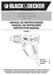
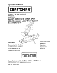
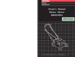
Questions? See us on the World Wide Web at www.dewalt.com
INSTRUCTION MANUAL
DW744XP-XE
HEAVY-DUTY 254 MM (10") JOB SITE TABLE SAW
14. Disconnect tool.
Shut off power and wait for the tool to come to a complete standstill before leaving it unattended. Unplug the
tool when not in use, before servicing or changing accessories.
15. Remove adjusting keys and wrenches.
Always check that adjusting keys and wrenches are removed from the tool before operating the tool.
16. Use appropriate tool.
The intended use is described in this instruction manual. Do not force small tools or attachments to do the job
of a heavy-duty tool. The tool will do the job better and safer at the rate for which it was intended.
WARNING! The use of any accessory or attachment or performance of any operation with this tool, other than
those recommended in this instruction manual may present a risk of personal injury.
17. Do not abuse cord.
Never carry the tool by its cord or pull it to disconnect from the socket. Keep the cord away from heat, oil and
sharp edges.
18. Maintain tools with care.
Keep the tools in good condition and clean for better and safer performance. Follow the instructions for
maintenance and changing accessories. Inspect the tool cords at regular intervals and, if damaged, have them
repaired by an authorized DEWALT repair agent. Inspect the extension cords periodically and replace them if
damaged. Keep all controls dry, clean and free from oil and grease.
19. Check for damaged parts.
Before using the tool, carefully check it for damage to ensure that it will operate properly and perform its
intended function. Check for misalignment and seizure of moving parts, breakage of parts and any other
conditions that may affect its operation. Have damaged guards or other defective parts repaired or replaced as
instructed. Do not use the tool if the switch is defective. Have the switch replaced by an authorized DEWALT
repair agent.
20. Have your tool repaired by an authorized DEWALT repair agent.
This power tool is in accordance with the relevant safety regulations. To avoid danger, electric appliances
must only be repaired by qualified technicians.
Definitions: Safety Guidelines
The definitions below describe the level of severity for each signal word. Please read the manual and pay
attention to these symbols.
DANGER: Indicates an imminently hazardous situation which, if not avoided, will result in death or
serious injury.
WARNING: Indicates a potentially hazardous situation which, if not avoided, could result in death or
serious injury.
CAUTION: Indicates a potentially hazardous situation which, if not avoided, may result in minor or
moderate injury.
CAUTION: Used without the safety alert symbol indicates a potentially hazardous situation which, if not
avoided, may result in property damage.
IF YOU HAVE ANY QUESTIONS OR COMMENTS ABOUT THIS OR ANY DEWALT TOOL, CALL US AT: 1800 654 155
(Aust) or 0800 339258 (NZ).
SAFETY INSTRUCTIONS
When using power tools, always observe the safety regulationsapplicable in your country to reduce the risk of fire,
electric shockand personal injury. Read the following safety instructions beforeattempting to operate this product.
KEEP THESE INSTRUCTIONS IN A SAFE PLACE!
General
1. Keep work area clean.
Cluttered areas and benches can cause accidents.
2. Consider work area environment.
Do not expose power tools to humidity. Keep work area well lit. Do not use power tools in the presence of
flammable liquids or gases.
3. Guard against electric shock.
Prevent body contact with earthed surfaces (e.g., pipes, radiators, cookers and refrigerators). For use under
extreme conditions (e.g., high humidity, when metal swarf is being produced, etc.) electric safety can be
improved by inserting an isolating transformer or a (FI) earth-leakage circuit-breaker.
4. Keep children away.
Do not let children come into contact with the tool or extension cord. Supervision is required for inexperienced
operators.
5. Extension cords for outdoor use.
When the tool is used outdoors, always use extension cords intended for outdoor use and marked
accordingly.
6. Store idle tools.
When not in use, power tools must be stored in a dry place and locked up securely, out of reach of children.
7. Dress properly.
Do not wear loose clothing or jewellery. They can be caught in moving parts. Preferably wear rubber gloves
and non-slip footwear when working outdoors. Wear protective hair covering to keep long hair out of the way.
8. Wear safety goggles.
Also use a face or dust mask in case the operations produce dust or flying particles.
9. Beware of maximum sound pressure.
Take appropriate measures for the protection of hearing if the sound pressure of 85 dB(A) is exceeded.
10. Secure workpiece.
Keep proper footing and balance at all times.
11. Do not overreach.
Always check that adjusting keys and wrenches are removed from the tool before operating the tool.
12. Avoid unintentional starting.
Do not carry the plugged-in tool with a finger on the switch. Be sure that the switch is released when
plugging in.
13. Stay alert.
Watch what you are doing. Use common sense. Do not operate the tool when you are tired.
Additional Safety Rules for Saw Benches
• Do - protect the electrical supply line with a suitable fuse or circuit breaker.
• Do - make certain the blade rotates in the correct direction and that the teeth are pointing to the front of the
saw bench.
• Do - be sure all clamp handles are tight before starting any operation.
• Do - be sure all blade and arbor collars are clean and the recessed sides of the collars are against the blade.
• Do - keep the saw blade sharp and properly set.
• Do - keep hands out of the path of the saw blade.
• Do - shut off the power and wait for the saw blade to stop before servicing or adjusting the tool.
• Do - disconnect the saw from the mains supply before changing the blade or carrying out maintenance.
• Don’t - attempt to operate on anything other than the designated voltage.
• Don’t - use blades larger or smaller than those which are recommended.
• Don’t - force the cutting action. (Stalling or partial stalling of the motor can cause major damage. Allow the
motor to reach full speed before cutting.)
• Don’t - cut ferrous metals, non-ferrous metals or masonry.
• Don’t - use abrasive wheels.
• Don’t - apply lubricants to the blade when it is running.
• Don’t - place either hand in the blade area when the saw is connected to the power source.
• Don’t - use any blades other than those specified in this instruction manual.
• Don’t - operate the saw without the guards in place.
• Don’t - reach around behind the saw blade.
• Don’t - place hands closer than 150 mm from the saw blade while cutting.
• Don’t - use damaged or cracked saw blades.
Residual Risks
The following risks are inherent to the use of saws:
– injuries caused by touching the rotating parts
2
In spite of the application of the relevant safety regulations and the implementation of safety devices, certain
residual risks cannot be avoided. These are:
– Impairment of hearing.
– Risk of accidents caused by the uncovered parts of the rotating sawblade.
– Risk of injury when changing the blade.
– Risk of squeezing fingers when opening the guards.
– Health hazards caused by breathing dust developed when sawing wood, especially oak, beech and MDF.
A1
Package Contents
The package contains:
1 Partly assembled machine
1 Rip fence
1 Mitre gauge
1 TCT saw blade
1 Upper blade guard assembly
1 Table insert
1 Blade wrench
1 Arbor wrench
1 Dust extraction adapter
1 Instruction manual
1 Exploded drawing
• Check for damage to the tool, parts or accessories which may have occurred during transport.
• Take the time to thoroughly read and understand this manual prior to operation.
Description (fig. A1, A2)
Your DW744XP jobsite table saw has been designed to perform the four main sawing operations of ripping,
cross-cutting, bevelling and mitring easily, accurately and safely in wood, wood products and plastics. This unit is
designed for use with a 250 mm carbide-tipped blade.
A1
A2
1 On/off switch
13 Rip fence latch
2 Mounting holes
14 Dust extraction outlet (accepts dust
3 Mitre gauge
extraction adaptor)
4 Table
15 Blade/wrench storage
5 Upper blade guard
16 Fence rail
6 Table insert
17 Locking knobs
7 Rip fence
18 Fence slot
8 Rip scale indicator
9 Fine adjustment knob
10 Combined elevating and bevel control wheel
11 Bevel lock lever
12 Ripping position lock lever
A2
ELECTRICAL SAFETY
The electric motor has been designed for one voltage only. Always check that the power supply corresponds to the
voltage on the rating plate.
Mains Plug Replacement (U.K. & Ireland Only)
• Should your mains plug need replacing and you are competent to do this, proceed as instructed below. If you
are in doubt, contact an authorized DEWALT repair agent or a qualified electrician.
• Disconnect the plug from the supply.
• Cut off the plug and dispose of it safely; a plug with bared copper conductors is dangerous if engaged in a
live socket outlet.
• Only fit 13 Amperes BS1363A approved plugs fitted with the correctly rated fuse (1).
• The cable wire colours, or a letter, will be marked at the connection points of most good quality plugs. Attach
the wires to their respective points in the plug (see below). Brown is for Live (L) (2), blue is for Neutral (N)
(4) and green/yellow is for Earth (E).
3
B1
• Before replacing the top cover of the mains plug ensure that the cable restraint (3) is holding the outer sheath
of the cable firmly and that the leads are correctly fixed at the terminal screws.
B2
1
2
4
3
WARNING: Never use a light socket. Never connect the live (L) or neutral (N) wires to the earth pin
marked E or .
For 115 V units with a power rating exceeding 1500 W, we recommend to fit a plug to BS4343 standard.
Using an extension cable
If an extension cable is required, use an approved extension cable suitable for the power input of this machine
(see technical data). The minimum conductor size is 1.5 mm2.
When using a cable reel, always unwind the cable completely.
Also refer to the table below.
Conductor size (mm2)
0.75
1.00
1.50
2.50
4.00
Voltage
230
0
2.1
3.5
5.1
7.1
12.1
-
2.0
3.4
5.0
7.0
12.0
20.0
C1
C2
Cable rating (Amperes)
6
10
15
20
25
Cable length (m)
7.5
15
25
30 45
Amperes Cable rating (Amperes)
6
6
6
6
6
6
6
6
6
6
6
6
6
6
10
10
10
10
10 15
15
15
15
15 20
20
20
20
20 25
60
6
6
15
15
20
-
ASSEMBLY AND ADJUSTMENT
WARNING: Prior to assembly and adjustment always unplug the tool.
WARNING: The teeth of a new blade are very sharp and can be dangerous.
The machine is fully assembled except for the blade, rip fence, upperblade guard and table insert.
Fitting the Rip Fence (fig. B1, B2)
1. Raise the blade arbor to its maximum by rotating the control wheel (10) clockwise (fig. A1).
2. Place the saw blade onto the spindle in the order shown in figure C1. Make sure the teeth point down at the
front of the table.
3. Hold the spindle using the open-ended wrench and tighten the arbor nut by rotating clockwise using the arbor
wrench (fig. C2).
4. To remove the blade, proceed in reverse order.
The rip fence (7) can be installed on the left- or right-side of your table saw.
1. Locate the pin (19) with the slot (20) in the rip fence and align the opening (21) with the rip fence latch (22)
(fig. B1, B2).
2. Secure the rip fence by snapping both latches in place (fig. B2).
Mounting the Saw Blade (fig. A1, C1, C2)
WARNING: Always check the rip fence pointer and the riving knife after having changed the blade.
WARNING: Ensure the machine is disconnected from the power source.
4
Parallel Adjustment (fig. A2, D)
D
E
F
G
For optimum performance, the blade must be parallel to the mitre slots.
This adjustment has been made at the factory. To re-adjust:
1. Place the unit in upright position.
2. Using a 10 mm socket wrench, slacken the bracket fasteners (25)
slightly (fig. D).
3. Adjust the bracket (26) until the blade is parallel to the fence slot (18)
(fig. A2).
4. Tighten the bracket fasteners (25) to 11 Nm (fig. D).
BLADE HEIGHT ADJUSTMENT (FIG. A1)
The blade can be raised and lowered by turning the combined elevating
and bevel control wheel (10).
Make sure the top three teeth of the blade are just breaking through the
upper surface of the workpiece when sawing. This will ensure that the
maximum number of teeth are removing material at any given time, thus
giving optimum performance.
Adjusting the Rip Scale (fig. A1, E)
1.
2.
3.
4.
5.
6.
Remove the blade guard.
Unlock the lock lever (12) by pulling it up (fig. A1).
Unlock the bevel lock lever (11) and set the bevel angle to 0°.
Move the fence (7) until it touches the blade.
Lock the lock lever (12).
Loosen the rip scale pointer screws (27) and set the pointer (28) to
zero (fig. E).
7. Tighten the screws (27).
The rip scale reads correctly only when the fence is mounted to the right
of the blade.
Mounting the Riving Knife Assembly (fig. A1, F)
1. Raise the blade arbor to its maximum by rotating the blade height
adjustment wheel (10) clockwise (fig. A1).
2. Slacken the two bolts (29) (fig. F).
3. Align the slots (30) with the bolts (29) and insert the fence until the
tops of the slots rest on the bolts (fig. F).
NOTE: When properly aligned, the riving knife will be in line with
the blade at the table top and at the top of the blade. Check using a
straight edge in all bevel and blade height positions.
4. If adjustment is required, remove the blade guard and adjust the
shims (32).
5. Mount the blade guard on the bolts.
6. Retighten the bolts (29) securely.
WARNING: When properly aligned, the riving knife will be in
line with the blade at the table top and at the top of the blade.
Check using a straight edge in all bevel and blade height
positions.
WARNING: Correct mounting and alignment of the riving knife
and upper blade guard is essential to safe operation!
Mounting the Table Insert (fig. H)
1. Align the table insert (6) as shown and insert the tabs of the back of
the table insert into the holes on the back of the table.
2. Press down the front of the table insert.
3. The front of the table insert must be flush or slightly below the table
top. The rear should be flush or slightly above the table top. Adjust
using the four adjustment screws (33).
4. Turn the locking screw (see insert in fig. H) clockwise 90° to lock the
table insert in place.
WARNING: Never use the machine without the table insert.
Immediately replace the table insert when worn or damaged.
Bench Mounting (fig. A1)
• Holes (2) are provided in all four feet to facilitate bench mounting.
Two different sized holes are provided to accommodate different
sizes of bolts. Use either hole; it is not necessary to use both.
Always mount your saw firmly to prevent movement. To enhance the
portability, the tool can be mounted to a piece of 12.5 mm or thicker
plywood which can then be clamped to your work support or moved
to other job sites and reclamped.
• When mounting your saw to a piece of plywood, make sure that the
mounting screws do not protrude from the bottom of the wood. The
plywood must sit flush on the work support. When clamping the saw
to any work surface, clamp only on the clamping bosses where the
mounting screw holes are located. Clamping at any other point will
interfere with the proper operation of the saw.
• To prevent binding and inaccuracy, be sure the mounting surface is
not warped or otherwise uneven. If the saw rocks on the surface,
place a thin piece of material under one saw foot until the saw is firm
on the mounting surface.
5
H
WARNING: The mounting surface must have a 350 x 500 mm
opening to allow dust to escape.
J
K1
K2
L
Rail lock adjustment (fig. A1, J)
The rail lock has been factory-set. If you need to re-adjust, proceed as
follows:
1. Lock the lock lever (12) by pushing it down (fig. A1).
2.Adjust the nut (34) on the underside of your saw until the gap between
the Belleville washers (35) closes (fig. J).
3. Once the Belleville washers are almost touching, loosen the nut (34)
half a turn.
Bevel Stop and Pointer Adjustment (fig. K1, K2)
1. Raise the blade to its maximum by rotating the blade height
adjustment wheel (10) clockwise (fig. K1).
2. Unlock the bevel lock lever (11) by pushing it up and to the right.
3. Loosen the bevel stop screw (36).
4. Place a set square (37) on the table and up against the blade (38)
(fig. K2).
5. Adjust the bevel angle using the bevel lock lever (11) until the blade is
flat against the square.
6. Tighten the bevel lock lever (11).
7. Turn the bevel stop cam (39) until it firmly contacts the bearing block
(fig. K1).
8. Check the bevel angle scale. If adjustment is required, loosen the
pointer screw (40) and set the pointer to 0°.
9. Tighten the pointer screw (40).
10. Repeat the procedure at 45° for the 45° bevel stop, but do not adjust
the pointer.
Mitre Gauge Adjustment (fig. A3, L)
Your mitre gauge (3) is equipped with adjustable stops at 90° and 45°.
To adjust these stops, loosen the lock nuts (41) and set the adjusting
screws (42) as required.
Adjusting the Fence Parallel to the Blade (fig. A1, D)
The fence has been factory-set. If you need to re-adjust, proceed as
follows:
1. Unlock the rail lock lever (12).
2. Remove the upper blade guard (5).
3. Locate the rear pinion bearing and loosen the two hex bolts (25A) just
enough to allow side-to-side movement.
4. Move the fence over until it touches the side of the blade.
5. Adjust the fence parallel to the blade.
6. Tighten the hex bolts.
7. Lock the rail lock lever and check that the fence is parallel to the blade.
WARNING: If there is not enough travel in the pinion bearing
assembly, take the unit to an authorized DEWALT repair agent.
Fine Adjustment Knob (fig. D)
The fine adjustment knob is factory adjusted.
If adjustment is required, proceed as follows:
1. Turn the saw upside down and locate the front pinion bearing.
2. Using a narrow blade screwdriver, access the screw through the slot
(26A).
3. Loosen the screw by turning counterclockwise until the head touches
the inside of the bearing box.
4. Tighten the screw 1/2 of a turn.
5. Repeat this procedure for the rear pinion bearing.
INSTRUCTIONS FOR USE
WARNING:
• Always observe the safety instructions and applicable
regulations.
• Install the appropriate saw blade. Do not use excessively
worn blades. The maximum rotation speed of the tool must
not exceed that of the saw blade.
• Do not attempt to cut excessively small pieces.
• Allow the blade to cut freely. Do not force.
• Allow the motor to reach full speed before cutting.
• Make sure all locking knobs and clamp handles are tight.
• Never place either hand in the blade area when the saw is
connected to the electrical power source.
• Never use your saw for freehand cuts!
6
• Do not saw warped, bowed or cupped workpieces. There
must be at least one straight, smooth side to go against the
rip fence or mitre fence.
• Always support long workpieces to prevent kickback.
• Do not remove any off-cuts from the blade area while the
blade is running.
The attention of UK users is drawn to the "woodworking machines
regulations 1974" and any subsequent amendments.
Switching on and off (fig. A1)
The on/off switch of your saw bench offers multiple advantages:
– No-volt Release Function: should the power be shut off for any
reason, the switch has to be deliberately reactivated.
– Extra Safety: the hinged safety enclosure plate can be locked by
passing a padlock through the centre hasp. The plate also serves as
an "easy to locate" emergency stop button as pressure on the front of
the plate will depress the stop button.
To switch the machine on, press the green start button.
To switch the machine off, press the red stop button.
BASIC SAW CUTS
M1
WARNING:
• Connect a suitable dust extraction device during all sawing
operations.
Ripping (fig. A1, A2, M1, M2)
• Whenever possible, connect a dust extraction device
designed in accordance with the relevant regulations
regarding dust emission.
WARNING: Sharp edges.
1. Set the blade to 0°.
2. Lock the rip fence (7) (fig. A1).
3. Raise the blade until it is about 3.2 mm higher than the top of the
workpiece.
4. Hold the workpiece flat on the table and against the fence. Keep the
workpiece approx. 25 mm away from the blade.
WARNING: Keep both hands away from the path of the blade
(fig. M2).
5. Press the green button to switch ON and allow the blade to reach full
speed.
6. Slowly feed the workpiece underneath the guard, keeping it firmly
pressed against the rip fence. Allow the teeth to cut, and do not force
the workpiece through the blade. The blade speed should be kept
constant.
7. Always use a push stick (43) when close to the blade (fig. M1).
8. After completing the cut, switch the saw OFF, allow the blade to
stopand remove the workpiece.
Transporting (fig. A1)
•Always carry the machine at the hand indentations.
WARNING: Always transport the machine with the upper blade
guard fitted.
MAINTENANCE
Your DEWALT machine has been designed to operate over a long period of
time with a minimum of maintenance. Continuous satisfactory operation
depends upon proper tool care and regular cleaning.
M2
Lubrication (fig. N)
The motor and bearings require no additional lubrication. If raising
and lowering the blade becomes difficult, clean and grease the height
adjustment screws:
1. Turn the saw on its side.
2. Clean and grease the height adjustment threads as shown in figure N.
Use general purpose grease.
WARNING:
• Never push or hold the "free" or cut-off-side of the
workpiece.
• Do not cut excessively small workpieces.
• Always use a push stick when ripping small workpieces.
Cleaning
WARNING: To reduce the risk of serious personal injury, turn unit
off and disconnect machine from power source before cleaning. An
accidental start-up can cause injury.
To maintain correct operation of your saw, clean the table insert area
regularly. Remove saw dust, chips and any other debris. If using
compressed air, always wear approved eye protection.
Regularly clean the dust collection system:
1. Turn the saw on its side.
2. Remove the screws (44) (fig. O).
3. Remove all dust and resecure the access door (45) using the screws
(fig. O).
IMPORTANT: The guard and throat plate must be placed in position before
operating the saw.
N
Bevel Cuts
1. Set the required bevel angle (refer to the section "Adjusting the rip
scale").
2. Proceed as for ripping.
Cross-cutting and Bevel Cross-cutting
1. Remove the rip fence and install the mitre gauge in the desired slot.
2. Lock the mitre gauge at 0°.
3. Proceed as for ripping.
Mitre Cuts (fig. A1)
Accessories
1. Set the mitre gauge to the required angle.
2. Always hold the workpiece tightly against the face of the mitre gauge.
3. Proceed as for ripping.
WARNING: Since accessories, other than those offered by
DEWALT, have not been tested with this product, use of such
accessories with this tool could be hazardous. To reduce the
risk of injury, only DEWALT, recommended accessories should
be used with this product.
Compound Mitre
This cut is a combination of a mitre and a bevel cut.
1. Set the bevel to the angle required.
2. Proceed as for a cross-cut mitre.
O
Recommended accessories for use with your tool are available at extra
cost from your local service center. If you need any assistance in locating
any accessory, please contact DEWALT Industrial Tool Co., 20 Fletcher
Road, Mooroolbark, VIC 3138 Australia or call 1800 654 155 or (NZ)
0800 339258.
Support for Long Pieces
Always support long pieces.
Support long workpieces using any convenient means such as sawhorses or similar devices to keep the ends from dropping.
The following attachments are available:
– legstand DE7440
Dust Extraction (fig. A2)
WARNING: Sharp edges.
The machine is provided with dust extraction outlets (5, 14). An adaptor is
provided for outlet (14).
7
Unwanted Tools and the Environment
Take your tool to an authorized DEWALT repair agent where it will
bedisposed of in an environmentally safe way.
Service Information
Please have the following information available for all service calls:
Model Number _____________ Serial Number _________________
Date and Place of Purchase __________________________________
Repairs
To assure product SAFETY and RELIABILITY, repairs, maintenance and
adjustments should be performed by a DEWALT factory service center,
a DEWALT authorized service center or other qualified service personnel.
Always use identical replacement parts.
Guarantee
Applicable to hand held Power Tools, Lasers and Nailers.
Three Year Limited Warranty
DEWALT will repair, without charge, any defects due to faulty materials or
workmanship for three years from the date of purchase. Please return the
complete unit, transportation prepaid, to any DEWALT Service Centre, or
any authorised service station.
For warranty repair information, call (AUS) 1800 654 155 or (NZ) 0800
339258.
This warranty does not apply to
• Accessories
• Damage caused where repairs have been made or attempted by
others.
• Damage due to misuse, neglect, wear and tear, alteration or
modification.
This warranty gives you specific legal rights and you may have other rights
under the provisions of the Consumer Guarantee Act 1993 (New Zealand
only), Trade Practices Act 1974 and State Legislation (Australia only).
In addition to the warranty, DEWALT tools are covered by our:
FREE ONE YEAR SERVICE CONTRACT
DEWALT will also maintain the tool for free at any time during the first year
of purchase. This includes labour, parts and lubrication required to restore
the product to sound mechanical and/or electrical condition. Normal wear
parts are not covered in this service. Carbon brushes worn more then
50% will be replaced.
NOTE: Three Year Warranty is not applicable to items deemed as
consumables. Radial arm saws are covered by a one (1) year warranty
only. DEWALT reserves the right to review its warranty policy prior to
launch of any new business development products.
30 DAY NO SATISFACTION GUARANTEE
If you are dissatisfied with any DEWALT power tool, laser or nailer, for any
reason, simply return it to the point of purchase with your sales receipt
within 30 days for a replacement unit or a full refund.
FREE WARNING LABEL REPLACEMENT: If your warning labels become
illegible or are missing, call (AUS) 1800 654 155 or (NZ) 0800 339258
for a free replacement.
Specifications
Voltage
Motor power (input)
Motor power (output)
No load speed
Blade diameter
Blade bore
Depth of cut at 90˚
Depth of cut at 45˚
Ripping capacity
Overall dimensions
Weight
Lpa (sound pressure)
Lwa (acoustic pressure)
DW744XP-XE
V
W
W
min-1
mm
mm
mm
mm
mm
mm
kg
db(A)•
db(A)•
• at operator's ear
8
220-240
2000
1300
3000
250
15.88 (5/8")
77
56
610
570 x 700 x 410
29
91
104
9
10
11
DEWALT Industrial Tool Co.,
20 Fletcher Road, Mooroolbark, VIC 3138 Australia (03 8720 5100) • 5 Te Apunga Place, Mt Wellington, New Zealand (0800 339258)
(AUG08)
Part No. 662700-00
DW744XP-XE
Copyright © 2008 DEWALT
The following are trademarks for one or more DEWALT power tools: the yellow and black color scheme; the “D” shaped air intake grill; the array of pyramids on the handgrip; the kit box configuration; and the array of lozenge-shaped humps
on the surface of the tool.