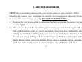
1
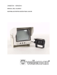
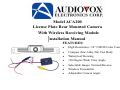
Model ACA200
License Plate Rear Mounted Camera
With Wireless Receiving Module
Installation Manual
FEATURES:
●
High Resolution: 1/4” CMOS Color Camera
●
Compact Zinc Alloy Die Cast Body
●
Waterproof Housing
●
130 Degree Wide View Angle
●
Selectable Image: Normal/Reverse
●
Wireless Transmitter
●
Adjustable Camera Angle
TABLE OF CONTENTS
1.
2.
3.
4.
5.
6.
7.
8.
9.
Warnings
Product Description
Packing List
Camera Installation
Wireless Receiver Installation
Camera Wiring Diagrams
Specifications
2
4
5
6
9
11
12
Troubleshooting
FCC Statement
13
15
1
Warnings
This product is intended to assist in safe driving and to allow the driver to have
a broader rear view while the vehicle is in reverse. You, as the driver, are solely
responsible for the safe operation of your vehicle and the safety of your
passengers according to local traffic regulations. Do not use any features of this
system to the extent it distracts you from safe driving. Your first priority while
driving should always be the safe operation of your vehicle. Audiovox
Electronics Corporation cannot accept any responsibility whatsoever for
accidents resulting from failure to observe these precautions or safety
instructions.
2
1.
This product utilizes high voltage. Any unauthorized modifications or damage to the
product may result in electrical shock. Handle all components with care. Inspect
regularly for damage to components and cabling.
2.
You are responsible for ensuring that the installation of this product does not void or
affect the vehicle manufacturer’s warranty. Audiovox Electronics Corporation or its
subsidiaries are not liable in full or in part for improper installation resulting in loss
or damage to your property, or for voiding all or part of the vehicle manufacturer’s
warranty.
3.
Do not apply excessive force to any of the components contained within this kit.
Excessive force used before, during or after installation that results in a damaged or
non-functional part will void all warranties.
4.
Please follow the procedures in this installation manual. Improper installation or
modification of this product will void all warranties.
3
Product Description
This revolutionary camera design integrates a wireless backup camera with your vehicle’s rear
license plate without covering the license plate. The camera is easy to mount on your car, truck,
or van with the bracket being hidden by your license plate.
This Wireless Camera transmits a signal using a 2.4 GHz frequency. Reception can be affected
by use of other wireless products utilizing the same frequency, i.e. cell phones and Bluetooth
products. Static or scrolling lines on the monitor are a normal and may be caused by other
wireless products. This is not the result of a defective product.
The wireless receiver has been developed to convert a hard wire camera/monitor system to a
wireless operation. The following information contained in the installation manual is for
camera backup systems. Note: this product can be used on any Camera/Monitor system.
4
Packing List
1.
CMOS Camera − 1 qty
2.
Wireless Receiving Module − 1 qty
3.
Theft-proof Screws: 2 each course thread and machine thread
4.
Flat Washer, 6mm − 2 qty
5.
Anti-Theft Allen Key − 1 qty
6.
Wire connectors:
a)
Tap connectors-3 qty
b)
Ring connector-1 qty
7.
Warranty Card
8.
Owners Manual
5
Camera Installation
NOTE: The transmitting antenna is located in the camera’s wire shielding. When
installing the camera wire, straighten the wire for best transmission, allowing the monitor
to receive the clearest image possible. DO NOT CUT THIS WIRE.
1.
Remove the rear license plate to determine the best way to run the power wires to the
reverse lights.
2.
The camera cable can be routed through an existing grommet, or through a 5/8 inch
hole drilled near the vehicle’s rear license plate. Be sure to check behind the intended
drilling location before drilling to ensure no wires or mechanisms interfere or could
be damaged during drilling. Check for interference with license plate lights and the
hatch release switch and/or mechanism. If not using an existing factory grommet, drill
a 5/8 inch hole at the selected location. Coat the edge of the hole with rust
6
preventative. Route the camera cable connector through the hole and insert the
grommet into the hole to prevent water from entering into the vehicle.
3.
Place the camera bracket behind the license plate and line up the holes. Fasten the
camera mounting bracket and the license plate to the vehicle using the anti-theft
screws provided. After installation of screws with the tool provided, place the tool in
the glove compartment or other safe place for future use.
4.
Wire the Camera to the vehicle’s reverse lamp.
a)
Locate the reverse lamp in the tail light assembly. Using the tap connector
supplied, perform the following steps:
i.
Place the un-stripped positive lead wire on the run channel.
ii.
Insert the un-stripped red power wire completely.
iii.
Fold the tap connector back over the wires and make the connection by
crimping the u-contact down flush with the plastic insulator.
7
iv.
b)
Close the top hinged cover until latched.
Attach the black wire to the ground.
i.
Place the un-stripped ground lead wire on the
Tap/Run Connection
run channel.
ii.
Insert the un-stripped black ground wire completely.
iii.
Fold the tap connector back over the wires and make the connection by
crimping the u-contact down flush with the plastic insulator.
iv.
c)
Close the top hinged cover until latched.
Reverse/Normal Image Jumper: The blue jumper wire loop is located at the
camera cable connector, installed in the harness. The camera image is pre-wired
for reverse image. If mounting the camera on the front of the vehicle, cut the
blue wire loop to change the camera image to normal. Secure cut wires with
electrical tape.
8
Receiver Installation
The receiver must be installed in the vehicle’s trunk or interior. The receiver are not
weather proof and must be located in a dry location
Tap/Run Connection
1.
Wiring the receiver connection.
a.
Wiring the receiver to the vehicle. Choose a source that only has power
when the vehicle is running. Connect as shown using the tap connectors
supplied.
i. Place the unstripped ignition source wire on the run channel
ii. Place the unstripped red power wire completely.
iii. Fold the tap connector back over the wires and make the
9
connection by crimping the u-contact down flush with the plastic
connector.
iv. Close the top hinged cover until latched.
b.
Black wire-Chassis/Ground. Using ground ring supplied,
i. Place stripped wire (1/4”) inside connector.
ii. Crimp the connector using a crimping tool to secure the wire.
iii. Connect to a vehicle body grounded screw (bare metal) directly.
2.
Wiring the receiver to the monitor
a.
Connect the receivers RCA connector to the monitor RCA connector.
10
Camera Wiring (Color Camera View)
Camera Wiring
11
Specifications
1.
Voltage: DC12V
2.
Operating Current:
a.
Transmitter: 130 mA
b.
Receiver: 180mA
3.
Signal System: NTSC
4.
Image Sensor: ¼” CMOS Sensor
5.
Horizontal Resolution: 480 lines
12
6.
Viewing Angle: 130 degrees
7.
Minimum Illumination: 0.3Lux
8.
Image Display: Selectable Normal/Reverse Image
9. Wireless Transmission Operating Frequency: 2.4GHz
10. Operating temperature: 0°C-50°C
11. Adjustable Viewing Angle
12. Camera Outer Dimensions: 25mm (W) x 30mm (H) x 62mm (D)
Troubleshooting
Symptoms
No video signal appears
Solutions
1. Check the rear view camera lens and clean if
13
while reversing the
vehicle
needed.
2. Check the rear view camera wiring and
connection.
Video image is not sharp
enough
Clean the camera lens.
Symptoms
Solutions
The Monitor is not on
after the vehicle is started
and vehicle is in reverse?
Check the monitor and the receiver wiring and
connection.
No video signal appears
while
reversing
the
vehicle?
Check the rearview Camera wiring connection.
14
Video image is not sharp
enough?
Clean the lens of the camera.
FCC STATEMENT
1. This device complies with Part 15 of the FCC Rules.
Operation is subject to the following two conditions:
a. This device may not cause harmful interference, and
b. This device must accept any interference received, including interference
that may cause undesired operation.
2. Changes or modifications not expressly approved by the party responsible for
15
compliance could void the user’s authority to operate the equipment
16
17