1
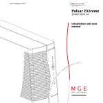
Pulsar EXtreme
1500/2000/2500/3000 VA
installation and user
manual
51033211EN/AA
- Page 1
Introduction
Thank you for selecting an MGE UPS SYSTEMS product to protect your electrical equipment.
The Pulsar EXtreme range has been designed with the utmost care. We recommend that you take the time
to read this manual to take full advantage of the many features of your UPS.
MGE UPS SYSTEMS pays great attention to the environmental impact of its products. Measures that have
made Pulsar EXtreme a reference in environmental protection include:
◗ production in an ISO 14001 certified factory;
◗ recycling of Pulsar EXtreme at the end of its service life.
To discover the entire range of MGE UPS SYSTEMS products and the options available for the Pulsar
EXtreme range, we invite you to visit our web site at Erreur! Signet non défini. or contact your MGE UPS
SYSTEMS representative.
Page 2 - 51033211EN/AA
Safety
Safety rules
Safety of persons
A UPS has its own internal power source (the battery). Consequently, the power outlets may be energized
even if the UPS is disconnected from the AC-power source.
Dangerous voltage levels are present within the UPS. It should be opened exclusively by qualified
service personnel.
The UPS must be properly earthed. If it is connected to the AC-power source via a wall outlet,
measurements are required to ensure that the total leakage current of the UPS and the protected
equipment does not exceed 3.5 mA. If the total leakage current exceeds this value, the INSTALL
version is mandatory and the earth wire must be connected to the input terminal block.
The battery supplied with the UPS contains small amounts of toxic materials. To avoid accidents,
the directives listed below must be observed.
◗ Never operate the UPS if the ambient temperature and relative humidity are higher than the levels
specified in the documentation.
◗ Never burn the battery (risk of explosion).
◗ Do not attempt to open the battery (the electrolyte is dangerous for the eyes and skin).
◗ Comply with all applicable regulations for the disposal of the battery.
Product safety
UPSs connected to the AC-power source via a wall outlet must remain in the immediate vicinity of the outlet.
The outlet must be easily accessible. For UPSs connected to the AC-power source via a terminal block,
a protection circuit breaker must be installed upstream and be easily accessible.
The UPS can be disconnected from the AC-power source by removing the power cord or the UPS
power cable.
◗ Never install the UPS near liquids or in an excessively damp environment.
◗ Never let a liquid or foreign body penetrate inside the UPS.
◗ Never block the ventilation grates on the front or back of the UPS.
◗ Never expose the UPS to direct sunlight or a source of heat.
Special precautions
The UPS connection instructions contained in this manual must be followed in the indicated order.
Check that the indications on the rating plate correspond to your AC-power system and to the actual
electrical consumption of all the equipment to be connected to the UPS.
If the UPS is positioned flat, check that not more than five modules are stacked on top of each other.
If the UPS must be stored prior to installation, storage must be in a dry place.
The admissible storage temperature range is -40° C to +50° C.
If the UPS remains de-energized for a long period, we recommend that you energize the UPS
for a period of 24 hours, at least once every month.
This charges the battery, thus avoiding possible irreversible damage.
51033211EN/AA
- Page 3
Foreword
Using this document
Information may be found primarily by consulting:
◗ the contents;
◗ the index.
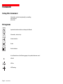
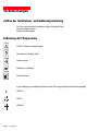
Pictograms
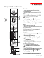
Important instructions that must always be followed.
Information, advice, help.
Visual indication.
Action.
Audio indication.
In the illustrations on the following pages, the symbols below are used:
LED off.
LED on.
LED flashing.
Page 4 - 51033211EN/AA
Contents
1.
Presentation
1.1
Pulsar EXtreme range ................................................................................................................. 7
Tower model .................................................................................................................................... 7
Rack model ..................................................................................................................................... 7
1.2
Connection modules .................................................................................................................. 8
Fault tolerant ................................................................................................................................... 8
Hot swap ......................................................................................................................................... 8
Install ............................................................................................................................................... 8
2.
1.3
Back ............................................................................................................................................. 9
1.4
Control panel ............................................................................................................................... 10
Installation
2.1
Unpacking and checks ............................................................................................................... 11
"Tower" model ............................................................................................................................... 11
"Rack" model ................................................................................................................................ 12
2.2
Installation (rack version) .......................................................................................................... 13
2.3
Connection to the RS 232 communications port (optional) ................................................... 14
2.4
Installation of the communications-card option ...................................................................... 14
2.5
Securing and connecting the connection modules ................................................................. 15
Securing the connection modules ................................................................................................. 15
Fault tolerant ................................................................................................................................. 15
Hot swap ....................................................................................................................................... 16
Install ............................................................................................................................................. 17
3.
Operation
3.1
Operating mode .......................................................................................................................... 18
ON-LINE mode ............................................................................................................................. 18
ECO mode .................................................................................................................................... 18
3.2
Start-up ........................................................................................................................................ 19
3.3
Bargraph indications .................................................................................................................. 19
51033211EN/AA
- Page 5
Contents
3.4
Failure of AC input power and operation on battery power .................................................... 20
Transfer to battery power .............................................................................................................. 20
Threshold for the low-battery shutdown warning .......................................................................... 20
End of backup time ....................................................................................................................... 20
Sleep mode ................................................................................................................................... 20
Return of AC input power .............................................................................................................. 20
3.5
Personalization ........................................................................................................................... 21
Function ........................................................................................................................................ 21
"ON / OFF conditions" tab ............................................................................................................. 21
"Battery" tab .................................................................................................................................. 22
"Output" tab ................................................................................................................................... 22
"By-pass" tab ................................................................................................................................ 22
"ECO mode" tab ............................................................................................................................ 23
3.6
4.
Shutdown ..................................................................................................................................... 23
Maintenance
4.1
Troubleshooting .......................................................................................................................... 24
4.2
UPS replacement ........................................................................................................................ 26
Fault-tolerant connection module .................................................................................................. 26
Hot-swap and Install connection modules .................................................................................... 27
Page 6 - 51033211EN/AA
5.
Environment ..................................................................................................................................... 28
6.
Appendices
6.1
Glossary ....................................................................................................................................... 29
6.2
Index ............................................................................................................................................. 31
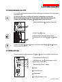
1. Presentation
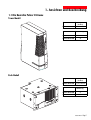
1.1 Pulsar EXtreme range
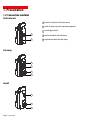
Tower model
Dimensions in mm
(H x W x D)
EXtreme 1500 to 3000
443 x 173 x 465
Weight in kg
EXtreme 1500 to 2000
29
EXtreme 2500 to 3000
36
Rack model
Dimensions in mm
(H x W x D)
EXtreme 1500 to 3000
177 (4U) x 483 x 462
Weight in kg
EXtreme 1500 to 2000
31
EXtreme 2500 to 3000
38
51033211EN/AA
- Page 7
1. Presentation
1.2 Connection modules
Fault tolerant
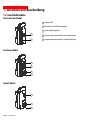
1 socket for connection to AC-power source.
2 outlets for direct connection to protected equipment.
3 manual bypass switch.
1
2
Hot swap
3
1
5
2
Install
3
5
4
Page 8 - 51033211EN/AA
4 input terminal block with cable clamp.
5 output terminal block with cable clamp.
1. Presentation
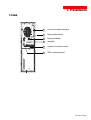
1.3 Back
6
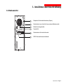
slot for communications-card option.
7
battery module connector.
8
battery circuit breaker.
9
rating plate.
10
connector for connection modules.
11
RS232 communications port.
51033211EN/AA
- Page 9
1. Presentation
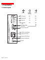
1.4 Control panel
Page 10 - 51033211EN/AA
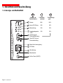
Alarms
% battery
␣ ␣ remaining
% load
14
UPS overload
100%
100%
15
electronics fault
80%
80%
16
battery fault
50%
50%
17
ambient temp.
> 40°C
20%
20%
18
hold down to display
percent load.
19
lamp test or buzzer OFF.
20
operation on manual bypass.
21
operation in ECO mode.
22
operation in ON-LINE mode.
23
operation on battery power.
24
ON/OFF.
2. Installation
2.1 Unpacking and checks
Tower model
29
26
25
27
28
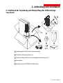
25 RS 232 communications cable.
26 "Solution Pac" CD ROM.
27 "UPS Driver" diskette for UPS personalization.
28 documentation.
29 electrical power cord (except INSTALL version).
51033211EN/AA
- Page 11
2. Installation
Rack model
30
29
26
25
25 RS 232 communications cable.
26 "Solution Pac" CD ROM.
27 "UPS Driver" diskette for UPS personalization.
28 documentation.
29 electrical power cord (except INSTALL version).
30 telescopic rails for mounting in 19" bay with mounting hardware.
Page 12 - 51033211EN/AA
27
28
2. Installation
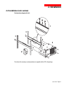
2.2 Installation (rack version)
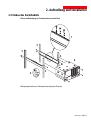
Rack mounting diagram with rails.
1
3
3
3
4
3
2
The rails and the necessary mounting hardware are supplied with the UPS in the package.
51033211EN/AA
- Page 13
2. Installation
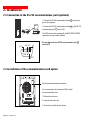
2.3 Connection to the RS 232 communications port (optional)
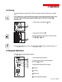
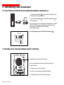
1. Connect the RS 232 communications cable 25 to the serial
port on the computer.
2. Connect the RS 232 communications cable 25 to the RS 232
communications port 11 on the UPS.
The UPS can now communicate with all MGE UPS SYSTEMS
supervision, set-up or safety software.
Pin-out diagram for the RS 232 communications port 11
on the UPS.
RD TD
OV
5
4
9
3 2
8
1
7 6
RTS
2.4 Installation of the communications-card option
Slot for the communications-card option.
It is not necessary to shut down the UPS to install
the communications card:
1. Remove the slot cover.
2. Insert the card in the slot.
3. Secure the card with the two screws.
Page 14 - 51033211EN/AA
2. Installation
2.5 Securing and connecting the connection modules
Securing the connection modules
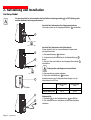
1. Insert the connection module in the connector 10 .
10
2. Secure the connection module to the UPS using
the two screws 31 .
31
31
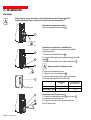
Fault tolerant
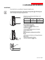
Before carrying out any connections, check that the battery circuit breaker 8
electrical power cord to the AC-power source is disconnected.
is OFF and that the
Connection of equipment:
Connect the protected equipment directly to the outlets 2 .
2
1
Connection to the AC-power source
29
1. Connect the electrical power cord 29 to the socket 1
for connection to AC-power source.
2. Connect the other end of the electrical power cord
to an AC-power outlet.
51033211EN/AA
- Page 15
2. Installation
Hot swap
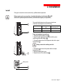
Before carrying out any connections, check that the battery circuit breaker 8 is OFF
and that the electrical power cord to the AC-power source is disconnected.
Connection of equipment to outlets
Plug your equipment into the outlets 2 .
2
8
32
33
Connection of equipment to a terminal block:
This type of connection must be carried out by qualified
electrical personnel.
1. Remove the terminal-block cover 32 .
2. Insert the cable supplying the equipment through the cable
clamp 33 .
3. Connect the three wires to the output terminal block 5 .
Always connect the earthing wire first.
4. Remove the terminal-block cover.
5. Tighten the nut on the cable clamp 33 .
5
The overall cable diameter and the cross-sectional area
of the three wires depends on the UPS rating.
cable diameter
(mm)
Earthing wire
1
29
Page 16 - 51033211EN/AA
cross-sectional area
of each wire (mm2)
EXtreme 1500 to 2000
9 to 12
1 to 4
EXtreme 2500 to 3000
9 to 12
1,5 to 4
Connection to the AC-power source:
1. Connect the electrical power cord 29 to the socket 1
for connection to AC-power source.
2. Connect the other end of the electrical power cord
to an AC-power outlet.
2. Installation
Install
This type of connection must be carried out by qualified electrical personnel.
Before carrying out any connections, check that the battery circuit breaker 8 is OFF
and that the upstream protection devices (AC distribution system) are open (OFF).
8
The overall cable diameter and the cross-sectional area
of the three wires depends on the UPS rating.
cable diameter
(mm)
cross-sectional area
of each wire (mm2)
EXtreme 1500 to 2000
9 to 12
1 to 4
EXtreme 2500 to 3000
9 to 12
1,5 to 4
32
Power and equipment connections:
1. Remove the terminal-block cover 32 .
2. Insert the cable supplying the equipment and the power
cable through the cable clamps 33 .
3. Connect the three wires of the equipment cable to the output
terminal block 5 .
Always connect the earthing wire first.
33
4. Connect the three wires of the power cable to the input
terminal block 4 .
5. Refit the terminal_block cover.
6. Tighten the nut on the cable clamp 33 .
Earthing wires
5
4
51033211EN/AA
- Page 17
3. Operation
3.1 Operating mode
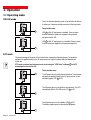
ON-LINE mode
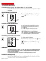
This is the standard operating mode, set by default in the factory.
It makes use of electronic double conversion of the input power.
Two possible cases:
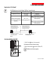
22
LED 22 is ON: AC input power is available. Power is drawn
from the distribution system and supplied to the protected
equipment via the UPS.
LED 23 is ON: AC input power is not available. Power is drawn
from the battery and supplied to the protected equipment.
23
ECO mode
The main advantage of this mode is that it reduces the consumption of electrical power. The protected
equipment is supplied directly by the AC-power source as long as it remains within the tolerances set
by the user.
ECO mode is selected and tolerance levels are set using the "UPS Driver" software 27 for UPS
personalization (see section 3.5).
Three possible cases:
21
The AC-power source is within the set tolerances. The protected
equipment is supplied directly by the AC-power source, via the
automatic bypass. LED 21 is ON.
The AC-power source is not within the set tolerances. The UPS
automatically shifts to ON-LINE mode. LED 22 is ON.
22
The AC-power source is not available. LED 23 is ON.
The battery supplies power to the protected equipment.
23
Page 18 - 51033211EN/AA
3. Operation
3.2 Start-up
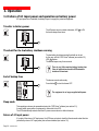
The protected equipment connected to the UPS can be energized, whether AC input power is available
or not.
Prior to initial start-up, check the UPS voltage settings. If the protected equipment voltage is other
than 230 V / 50 Hz, the UPS settings must be modified using the "UPS Driver" software 27
(see section 3.5).
1. Set the battery circuit breaker(s) 8 to ON.
8
2. Press the ON / OFF button 24 .
All connected equipment is energized. The buzzer sounds.
LEDs 21 , 22 and 23 go ON.
24
If LEDs 21 , 22 and 23 do not go ON or if LEDs 14 , 15 , 16 or 17 flash, there is a fault (see section 4.1).
3.3 Bargraph indications
LEDs 14 to 17 provide three different indications.
1. Remaining backup time in percent.
14
15
16
17
18
2. Percent load drawn by the protected equipment,
when button 18 is pressed.
3. Operating faults (flashing LED and beeps):
14 Overload.
15 UPS fault.
16 Battery fault.
17 Excessive ambient temperature.
51033211EN/AA
- Page 19
3. Operation
3.4 Failure of AC input power and operation on battery power
AC input power is not available, the battery steps in to supply the protected equipment.
Transfer to battery power
The AC-power source is outside tolerances, LED 23 is ON,
the buzzer beeps three times.
23
Threshold for the low-battery shutdown warning
The low-battery shutdown warning threshold can be set
by the user, with the "UPS Driver" software (see section 3.5).
LED 23 flashes.
The buzzer beeps every three seconds.
23
There is very little remaining battery backup time.
Close all applications because UPS automatic
shutdown is imminent.
End of backup time
The buzzer sounds continuously.
Press button 19 to turn the buzzer OFF.
19
The equipment is no longer supplied with power.
Sleep mode
This operating mode may be personalized using the "UPS Driver" software (see section 3.5).
It saves battery power when no equipment is connected to the UPS.
The UPS automatically restarts when the AC-power source returns to within tolerances.
Return of AC input power
If, in spite of the return of AC input power, the UPS does not restart, check that the automatic-restart function
(activated by return of AC input power) has not been disabled (see section 3.5).
Page 20 - 51033211EN/AA
3. Operation
3.5 Personalization
Function
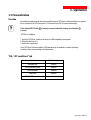
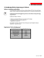
Personalization parameters can be set and modified using the "UPS Driver" software installed on a computer
that is connected to the UPS (see section 2.3 Connection to the RS 232 communications port).
Check that the RS 232 cable 25 is correctly connected and that the battery circuit breaker 8
is closed.
"UPS Driver" installation:
1. Insert the "UPS Driver" diskette in the drive of an IBM-compatible microcomputer.
2. Select the disk drive (A :\).
3. Double-click "upsdriv.exe".
Once "UPS Driver" has been installed, UPS parameters can be modified in a window containing
a number of tabs, each presenting a set of parameters.
"ON / OFF conditions" tab
Personalizable function
Default setting
Automatic start
Enabled
Cold start (battery power)
Enabled
Forced shutdown
Enabled
Sleep mode
Disabled
UPS ON / OFF via software
Enabled
51033211EN/AA
- Page 21
3. Operation
"Battery" tab
Personalizable function
Default setting
Options
"Battery test" intervals
Every day
Once a week
Once a month
No test
"Low-battery shutdown warning" threshold
20% remaining battery
backup time
40% remaining battery
backup time
Charger
Standard
CLA (2, 4 or 8 hours)
"Output" tab
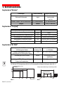
Rated AC-power source voltage (see figure 1)
230 V
200 V-208 V-220 V-240 V
Rated AC-power source frequency
50 Hz
60 Hz
Tolerance for AC-power source frequency (fig. 2)
± 5%
± 1% to ± 10% , in 1% steps
Frequency-regulation rate
Standard
Redundancy (see section 6.1)
Overload alarm level
100%
0 to 100%, in 10% steps
UPS restart after a short-circuit
Disabled
Enabled (click to add check)
Authorized voltage range for transfer to bypass
(see figure 3) if fault or overload
187 V to 265 V (for
230 V rated voltage)
187 V to 265 V,
in 1V steps
Authorized frequency range for transfer to bypass
(see figure 2) if fault or overload
± 10%
± 1% to ± 10%, in 1% steps
Transfer to bypass if overload
Enabled
Disabled (click to remove check)
Transfer to bypass following a fault, whatever
the conditions on the AC-power source
Disabled
Enabled (click to add check)
"By-pass" tab
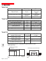
The value selected for the rated UPS voltage impacts on the power available at UPS output
(see the diagram below).
Available power as a percentage
of the rated power
Authorized frequency range for transfer to bypass
Tolerance for AC-power
source frequency
Fig. 1
Page 22 - 51033211EN/AA
Voltage in V
Mini
Fig. 2
Maxi
3. Operation
"ECO mode" tab
ECO mode is not possible unless it has first been authorized using the "UPS Driver" software
Personalizable function
Default setting
Options
ECO mode authorization
Disabled
(not authorized)
Enabled (click to check)
Authorized voltage range for
operation in ECO mode (see figure 3)
Range for minimum authorized
voltage for operation in ECO mode
200 V to 240 V
(for 230 V rated
voltage)
The upper threshold (max. voltage) is between
the maximum authorized voltage for transfer to
the bypass and the rated voltage.
The lower threshold (min. voltage) is between
the minimum authorized voltage for transfer to
the bypass and the rated voltage.
Range for maximum authorized
voltage for operation in ECO mode
Voltage in V
Minimum authorized voltage
for transfer to the bypas
Rated
voltage
Maximum authorized voltage
for transfer to the bypass
Fig. 3
3.6 Shutdown
1. Press button 24 (return to the OFF position).
The connected equipment is no longer supplied with power.
24
2. Set the battery circuit breaker(s) 8 to OFF.
The battery is no longer recharged.
8
51033211EN/AA
- Page 23
4. Maintenance
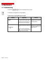
4.1 Troubleshooting
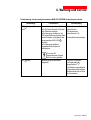
If any of LEDs 14 , 15 , 16 or 17 flash, there is a operating anomaly or an alarm.
If a LED flashes, the bargraph data is no longer displayed.
Troubleshooting not requiring MGE after-sales support
Indication
Signification
LED 14 flashes and the buzzer UPS overload. Overload is too long
beeps.
or too high. The UPS cuts the supply
of power to the connected equipment
and the buzzer sounds continuously.
The ambient temperature is higher than
40° C.
LED 17 flashes.
The UPS is not designed to
operate more than eight hours
under these conditions.
Page 24 - 51033211EN/AA
Correction
Check the power drawn by the
equipment and disconnect any
non-priority devices.
Install the UPS in a room where
the ambient temperature is not
greater than 40° C.
4. Maintenance
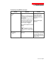
Troubleshooting requiring MGE after-sales support
Indication
Signification
LED 15 flashes and the buzzer
beeps.
UPS electronics have detected a UPS
fault.
Depending on the UPS personalization
parameters (see section 3.5), there are
two possibilities:
◗ the equipment connected to the UPS
continues to be supplied, but directly
from the AC-power source (via the
automatic bypass (LED 21 ON);
Correction
For UPSs equipped with Hot
swap or Install connection
modules, follow the UPS
replacement procedure (see
section 4.2).
Call the after-sales support
department.
the connected equipment is no longer
supplied.
◗
The equipment connected to
the UPS is no longer protected.
LED 16 flashes.
A battery fault was detected during the
battery test.
Make sure that the battery
circuit breaker(s) is closed.If that
is the case, call the after-sales
support department because the
battery is not OK
51033211EN/AA
- Page 25
4. Maintenance
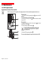
4.2 UPS replacement
Fault-tolerant connection module
Before carrying out this operation, the supply of power to the connected equipment must be cut.
24
8
Disconnection:
1. Shut down the UPS by pressing button 24 (return to the OFF
position).
2. Open the battery circuit breaker(s) 8 .
3. Remove the two fixing screws 31 and the connection module
from the UPS.
Reconnection:
1. Insert the connection module in the connector 10 and secure
using the two screws 31 .
2. Close the battery circuit breaker(s) 8 .
Check that UPS personalization settings still
correspond to the equipment to be supplied
(see section 3.5).
10
3. Start the UPS by pressing button 24 .
31
The connected equipment is again protected by the UPS.
31
Page 26 - 51033211EN/AA
4. Maintenance
Hot-swap and Install connection modules
Disconnection:
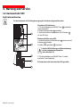
1. Turn the manual bypass switch 3 from the NORMAL
to the intermediate position.
2. Check that LED 21 is ON before continuing to the BYPASS
position.
Before turning the switch,
see the manual
NORMAL
BY-PASS
20
21
Before turning the switch,
see the manual
NORMAL
BY-PASS
If LED 21 is not ON, do not switch to the BYPASS
position and call the after-sales support
department.
3. Turn the manual bypass switch 3 from the intermediate
position to the BYPASS position.
The connected equipment is supplied by the AC-power source,
via the manual bypass.
4. Shut down the UPS by pressing button 24 (return to the OFF
position).
5. Open the battery circuit breaker(s) 8 .
6. Remove the two fixing screws 31 and the connection module
from the electronic module.
The UPS can be replaced. The connected equipment is
supplied by the AC-power source.
Reconnection:
1. Insert the connection module in the connector 10 and secure
using the two screws 31 .
2. Close the battery circuit breaker(s) 8 .
24
8
Check that UPS personalization settings still
correspond to the equipment to be supplied
(see section 3.5).
3. Start the UPS by pressing button 24 .
4. Check that LED 20 is ON before turning the manual bypass
switch 3 to the intermediate position.
If LED 20 is not ON, do not switch to the
intermediate position and call the after-sales
support department.
10
31
5. Turn the manual bypass switch 3 from the BYPASS position
to the intermediate position and check that LED 21 is ON.
6. Turn the manual bypass switch 3 from the intermediate
position to the NORMAL position.
The connected equipment is again protected by the UPS.
31
51033211EN/AA
- Page 27
5. Environment
This product has been designed to respect the environment:
It does not contain CFCs or HCFCs.
It was manufactured in a factory certified ISO 14001.
UPS recycling at the end of service life:
MGE UPS SYSTEMS undertakes to recycle, by certified companies and in compliance with all applicable
regulations, all UPS products recovered at the end of their service life (contact your branch office).
Packing:
UPS packing materials must be recycled in compliance with all applicable regulations.
Warning:
This product contains lead-acid batteries. Lead is a dangerous substance for the environment if it is not
correctly recycled by specialized companies.
Web site : www.mgeups.com
Page 28 - 51033211EN/AA
6. Appendices
6.1 Glossary
Authorized voltage
range for operation
in ECO mode
The range of voltage supplied by the AC-power source within which the UPS
can operate in ECO mode. In ECO mode, the equipment connected to the
UPS is supplied directly by the AC-power source, via the automatic bypass.
Authorized voltage
range for transfer to
bypass if fault or overload
Upper and lower voltage thresholds within which the UPS can operate
on the automatic bypass in the event of a UPS fault or overload.
Automatic bypass
Automatic switch controlled by the UPS, used to connect the equipment
directly to the AC-power source.
Automatic start following
return of AC input power
When AC input power returns following shutdown at the end of the battery
backup time, UPS automatic start can be enabled or disabled.
Backup time
Time that the connected equipment can operate on battery power.
Bargraph
Device on the front panel indicating the percent remaining backup time
or the percent load.
Battery test
Internal UPS test on battery status.
CLA (Long backuptime charger)
Module incorporating a charger for long backup times. The charger is powerful
enough to charge battery extension modules offering very long backup times.
Cold start
See "Start on battery power".
Connection module
Unit grouping the receptacles for connection to the AC-power source
and the equipment.
Dialog box
A window in a computer program displayed for selection by the user of various
options and parameter settings.
Double conversion
The power supplied to the connected equipment is completely regenerated
by continuous double conversion, i.e. the AC power from the AC-power source
is rectified (AC - DC), then converted back (DC - AC) to AC power.
ECO mode
Operating mode by which the equipment is supplied directly by the AC-power
source if it is within the tolerances defined by the user. This mode reduces
the consumption of electrical power.
Equipment
Devices or systems connected to the UPS output.
Fault tolerant
Connection module (without manual bypass) offering receptacles
for connection to the AC-power source and the equipment.
Forced shutdown
Ten-second interruption in the supply of power to the connected equipment
following a system shutdown, even if AC input power returns during
the interruption period.
51033211EN/AA
- Page 29
6. Appendices
Frequency-regulation rate
The rate at which the UPS frequency is synchronized with that
of the AC-power source. Two possible cases:
1. The installation comprises a single UPS. The frequency-regulation rate
is set to "Standard".
2. The installation comprises two UPSs connected in series. The AC-power
source supplies power to the first UPS which in turn supplies the second UPS.
The connected equipment is supplied by the second UPS.
The frequency regulation rate of the first UPS must be set to "Standard",
the frequency regulation rate of the second UPS must be set to "Redundancy".
Hot swap
Connection module (with manual bypass) offering a socket for connection
to the AC-power source and outlets or a terminal block for connection
to the equipment.
Install
Connection module (with manual bypass) offering terminal blocks
for connection to the AC-power source and the equipment.
Manual bypass
Rotary switch controlled by the user, used to connect the equipment directly
to the AC-power source. Transfer of the load to the manual bypass enables
UPS maintenance or replacement, without interrupting the supply of power
to the connected equipment.
ON-LINE mode
The normal UPS operating mode, by which the AC-power source supplies
the UPS, which in turn, following double conversion of the AC power,
supplies the connected equipment.
Percent load
Ratio between the power drawn by the connected equipment and the total
power that the UPS can supply.
Personalization
A number of UPS functions can be modified using the "UPS Driver" software
to better meet the user's needs.
Redundancy
See "Frequency-regulation rate".
Sleep mode
This function shuts down the UPS when it operates on battery power
and no load is detected on the UPS output.
Start on battery power
This function makes it possible to energize the connected equipment even
when AC input power is not available (operation exclusively on battery power).
Tolerance for AC-power
source frequency
The range of frequency supplied by the AC-power source within which
the UPS can operate in ON-LINE mode (double conversion).
UPS
Uninterruptible Power Supply.
UPS ON / OFF
via software
It is possible to enable or disable use of UPS ON / OFF controls
by the computer-system protection software.
Page 30 - 51033211EN/AA
6. Appendices
6.2 Index
A
L
AC power
Failure ........................................................... 20
Frequency tolerance ..................................... 22
Rated frequency ............................................ 22
Rated voltage ................................................ 22
Return ............................................................ 20
LEDs
Lamp test ....................................................... 10
M
Mode
ECO mode .......................................... 10-18-23
ON LINE mode ......................................... 10-18
B
Bargraph .............................................................. 19
Battery
Battery test .................................................... 22
End of backup time ....................................... 20
Fault ......................................................... 10-19
Low-battery shutdown warning ..................... 20
Recycling ....................................................... 28
Transfer to battery power .............................. 20
Buzzer ......................................................... 4-10-20
By-pass
Automatic bypass ..................................... 18-25
Manual bypass ......................................... 10-26
C
Communication .................................................... 14
Connection
Communications card ................................... 14
Connection modules ................................ 16-17
RS 232 communications port ........................ 14
E
ECO mode ................................................ 10-18-23
F
Fault (UPS)
Load .............................................................. 10
Transfer to automatic bypass ........................ 25
Fault tolerant ............................................... 8-15-26
H
Hot swap ..................................................... 8-16-27
O
Overload .................................................... 10-22-24
P
Personalization ...................................................
Battery ..........................................................
ECO mode ....................................................
ON / OFF conditions .....................................
Output ...........................................................
21
22
23
21
22
R
Rack .................................................................. 7-13
S
Safety .................................................................... 3
Shutdown
Forced shutdown ........................................... 21
UPS ON / OFF via software .......................... 21
UPS shutdown ......................................... 10-23
Sleep mode ................................................... 20-21
Software
UPS Driver .......................................... 11-12-21
Start-up
Automatic start .............................................. 21
T
Temperature
Excessive ambient temp .................... 10-19-24
U
UPS Driver ................................................ 11-12-21
I
Install ........................................................... 8-17-27
51033211EN/AA
- Page 31
140, Avenue Jean Kuntzmann
ZIRST - Montbonnot St Martin
38334 - ST ISMIER CEDEX - FRANCE
www.mgeups.com
51033211EN/AA
Page 32 - 51033211EN/AA
Nothing will stop you now
Publication : MGE UPS SYSTEMS, 11/99.
MGE UPS SYSTEMS
Pulsar EXtreme
1500/2000/2500/3000 VA
Installations- und
Bedienungsanleitung
51033211DE/AA
- Page 1
Einleitung
Wir danken Ihnen, daß Sie sich für ein Produkt von MGE UPS SYSTEMS zum Schutz Ihrer Anwendungen
entschieden haben.
Die Baureihe Pulsar EXtreme wurde mit größter Sorgfalt entwickelt.
Um die Leistungen Ihrer USV (Unterbrechungsfreien Stromversorgung) optimal nutzen zu können, empfehlen
wir Ihnen, sich ein wenig Zeit zu nehmen und das vorliegende Handbuch aufmerksam zu lesen.
Für MGE UPS SYSTEMS ist Umweltschutz ein wichtiger Aspekt bei der Entwicklung und Herstellung seiner
Produkte.
Ein hoher Forschungs- und Entwicklungsaufwand macht Pulsar EXtreme zu einem echten Musterbeispiel
für ein umweltfreundliches Produkt. Dabei sind folgende Aspekte hervorzuheben:
◗ Herstellung an einem Produktionsstandort gemäß ISO 14001,
◗ Recycling von Pulsar EXtreme nach Ablauf der Lebensdauer.
Entdecken Sie das umfassende Angebot von MGE UPS SYSTEMS sowie weitere Optionen zur Baureihe
Pulsar EXtreme auf unserer WEB-Site www.mgeups.com, oder wenden Sie sich persönlich an einen
Vertreter von MGE UPS SYSTEMS in Ihrer Nähe. Aufgrund ständiger Weiterentwicklung bleiben technische
Änderungen vorbehalten.
Page 2 - 51033211DE/AA
Sicherheit
Sicherheitsregeln
Personenschutz
Die USV verfügt über eine eigene interne Energiequelle (Batterie). Die Abgangssteckdosen können daher
unter Spannung stehen, selbst wenn die USV vom Leitungsnetz getrennt ist.
Gefährliche Spannung im Innern der USV. Öffnen des Gehäuses darf nur durch Fachpersonal
erfolgen.
Die USV muß in jedem Fall gemäß den gültigen Vorschriften geerdet werden. Bei Anschluß an das
elektrische Leitungsnetz über die Steckdose ist sicherzustellen, daß die Fehlerströme der USV und
der über sie gespeisten Systeme insgesamt nicht mehr als 3,5 mA betragen. Andernfalls muß die
FESTINSTALLATIONS-Version der USV verwendet und der Erdungsleiter an die Eingangsklemmleiste
angeschlossen werden.
Die zum Lieferumfang der USV gehörende Batterie in geringen Mengen enthält giftige Bestandteile.
Um jegliche Unfälle zu vermeiden, müssen folgende Regeln eingehalten werden:
◗ Die USV darf nicht in Betrieb genommen werden, wenn Umgebungstemperatur und Luftfeuchtigkeit
über den spezifizierten Grenzwerten liegen.
◗ Die Batterie darf nicht ins offene Feuer geworfen werden (Explosionsgefahr).
◗ Die Batterie darf nicht geöffnet werden (die enthaltene Säure kann Haut oder Augen verätzen).
◗ Die Entsorgung muß gemäß den geltenden gesetzlichen Bestimmungen erfolgen.
Geräteschutz
Bei Anschluß der USV an eine normale Netzsteckdose soll sich diese in der Nähe der USV befinden und
leicht zugänglich sein. Bei Netzanschluß der USV über die Klemmleiste muß ein Schutzorgan
(Sicherungsautomat) vorgeschaltet werden und leicht zugänglich sein.
Die Trennung vom Leitungsnetz erfolgt durch Herausziehen des Netzsteckers bzw. Abklemmen des
Einspeisekabels der USV.
◗ Die USV darf nicht in der Nähe von Flüssigkeiten oder in sehr feuchter Umgebung betrieben werden.
◗ Es dürfen keine Flüssigkeiten oder Fremdkörper in das Innere der USV eindringen.
◗ Die Lüftungsgitter an der Vorder- und Rückseite der USV dürfen nicht abgedeckt werden.
◗ Die USV darf nicht starkem Sonnenlicht oder der Einwirkung einer starken Wärmequelle ausgesetzt sein.
Besondere Vorsichtsmaßnahmen
Die Reihenfolge der in dieser Installations- und Bedienungsanleitung angegebenen Anschlußhinweise ist
einzuhalten.
Die Kenndaten auf dem Typenschild sind hinsichtlich der Übereinstimmung mit den vorhandenen
Netzparametern und der Leistungsaufnahme aller angeschlossenen Verbraucher zu überprüfen.
Bei liegender Aufstellung der USV dürfen maximal fünf Einheiten aufeinandergelegt werden.
Eine eventuelle Lagerung der USV vor ihrer Inbetriebnahme muß an einem trockenen Ort erfolgen.
Grenzwerte für die Lagertemperatur: -40°C bis +50°C.
Bei längerer Trennung vom Netz empfiehlt es sich, die USV etwa einmal pro Monat über 24 Stunden an
Spannung zu legen, um die Batterie aufzuladen, da diese sonst dauerhaft geschädigt werden kann.
51033211DE/AA
- Page 3
Vorbemerkungen
Aufbau der Installations- und Bedienungsanleitung
Die Suche nach bestimmten Informationen erfolgt auf einfachste Weise:
◗ über das Inhaltsverzeichnis,
◗ über das Stichwortregister.
Bedeutung der Piktogramme
WICHTIG, Hinweise unbedingt befolgen
Informationen, Ratschläge, Hilfen
Optische Anzeige
Maßnahmen, Handlungen
Akustischer Alarm
In den Abbildungen der nachfolgenden Seiten sind die LED-Anzeigen mit folgenden Symbolen dargestellt:
LED AUS
LED AN
LED blinkt
Page 4 - 51033211DE/AA
Inhalt
1.
Ansichten und Beschreibung
1.1
Die Baureihe Pulsar EXtreme .................................................................................................... 7
Tower-Modell ................................................................................................................................... 7
Rack-Modell .................................................................................................................................... 7
1.2
Anschlußmodule ......................................................................................................................... 8
Fault tolerant Modul ........................................................................................................................ 8
Hot Swap Modul .............................................................................................................................. 8
Install Modul .................................................................................................................................... 8
2.
1.3
Rückansicht ................................................................................................................................. 9
1.4
Anzeige- und Bedienfeld ............................................................................................................ 10
Aufstellung und Installation
2.1
Entfernen der Verpackung und Überprüfung des Lieferumfangs .......................................... 11
Tower-Modell ................................................................................................................................. 11
Rack-Modell .................................................................................................................................. 12
2.2
Einbau des Rack-Modells ........................................................................................................... 13
2.3
Anschluß des RS232-Kommunikationskabels (wahlweise) .................................................... 14
2.4
Einbau einer Kommunikationskarte (Option) ........................................................................... 14
2.5
Montage der Anschlußmodule ................................................................................................... 15
Befestigung der Anschlußmodule ................................................................................................. 15
Fault tolerant Modul ...................................................................................................................... 15
Hot-Swap Modul ........................................................................................................................... 16
Install Modul .................................................................................................................................. 17
3.
Betriebszustände
3.1
Betriebsarten ............................................................................................................................... 18
ONLINE-Mode .............................................................................................................................. 18
ECO-Mode .................................................................................................................................... 18
3.2
Inbetriebnahme der USV ............................................................................................................ 19
3.3
Balkenanzeige ............................................................................................................................. 19
51033211DE/AA
- Page 5
Inhalt
3.4
Batterieversorgung der Verbraucher bei Netzausfall .............................................................. 20
Umschaltung auf Batteriebetrieb ................................................................................................... 20
Voralarm "Ende der Autonomiezeit" .............................................................................................. 20
Abschaltung am Ende der Autonomiezeit ..................................................................................... 20
Sleep-Modus ................................................................................................................................. 20
Rückkehr der Netzspannung ........................................................................................................ 20
3.5
Kundenspezifische Anpassung per Software .......................................................................... 21
Software, Installation und Funktion ............................................................................................... 21
Registerkarte "Ein/Aus-Bedingungen" .......................................................................................... 21
Registerkarte "Batterie" ................................................................................................................. 22
Registerkarte "Ausgang" ............................................................................................................... 22
Registerkarte "BY-PASS" .............................................................................................................. 22
Registerkarte "ECO-Mode" ........................................................................................................... 23
3.6
4.
Ausschalten der USV .................................................................................................................. 23
Wartung und service
4.1
4.2
Fehlerbehebung .......................................................................................................................... 24
Austausch der USV ..................................................................................................................... 26
Fault tolerant-Version .................................................................................................................... 26
Hot-Swap- und Install-Version ...................................................................................................... 27
5.
6.
Page 6 - 51033211DE/AA
Umweltschutz .................................................................................................................................. 28
Anhang
6.1
Fachbegriffe ................................................................................................................................ 29
6.2
Stichwortregister ........................................................................................................................ 31
1. Ansichten und Beschreibung
1.1 Die Baureihe Pulsar EXtreme
Tower-Modell
Abmessungen in mm
(H x B x T)
EXtreme 1500 bis 3000
443 x 173 x 465
Gewicht in kg
EXtreme 1500 bis 2000
29
EXtreme 2500 bis 3000
36
Rack-Modell
Abmessungen in mm
(H x B x T)
EXtreme 1500 bis 3000
177 (4U) x 483 x 462
Gewicht in kg
EXtreme 1500 bis 2000
31
EXtreme 2500 bis 3000
38
51033211DE/AA
- Page 7
1. Ansichten und Beschreibung
1.2 Anschlußmodule
Fault tolerant Modul
1 Netzanschluß
2 Steckdosen für Verbraucherabgänge
3 Handumgehungsschalter
1
2
Hot Swap Modul
3
1
5
2
Install Modul
3
5
4
Page 8 - 51033211DE/AA
4 Eingangs-Klemmenanschlüsse mit Kabeleinführung
5 Ausgangs-Klemmenanschlüsse mit Kabeleinführung
1. Ansichten und Beschreibung
1.3 Rückansicht
6
Steckplatz für Kommunikationskarte (Option)
7
Steckverbinder zum Anschluß eines externen Batteriemoduls
8
Batterie-Leistungsschalter
9
Typenschild
10
Steckverbinder für Anschlußmodule
11
RS232-Kommunikationsschnittstelle
51033211DE/AA
- Page 9
1. Ansichten und Beschreibung
1.4 Anzeige- und Bedienfeld
Anzeige- und
Bedieneinheiten
Page 10 - 51033211DE/AA
14
Überlast
15
% Restautonomiezeit
% Auslastungsgrad
100%
100%
interne USV-Störung
80%
80%
16
Batteriestörung
50%
50%
17
Umgebungstemperatur
> 40°C
20%
20%
18
Auslastungsgrad
(Taste gedrückt halten):
19
Taster LED-Test und
Summerabschaltung
20
Betrieb über Handumgehung
21
ECO-Mode
22
ONLINE-Mode
23
Batteriebetrieb
24
Ein/Aus-Taster (ON/OFF)
2. Aufstellung und Installation
2.1 Entfernen der Verpackung und Überprüfung des Lieferumfangs
Tower-Modell
29
26
25
27
28
25 Verbindungskabel für RS232-Kommunikationsschnittstelle
26 CD ROM mit USV-Software Solution-Pac
27 Diskette mit Software UPS Driver zur kundenspezifischen Anpassung der USV
28 Dokumentation
29 Netzkabel (außer bei FESTINSTALLATIONS-Version)
51033211DE/AA
- Page 11
2. Aufstellung und Installation
Rack-Modell
30
29
26
25
27
25 Verbindungskabel für RS232-Kommunikationsschnittstelle
26 CD ROM mit USV-Software Solution-Pac
27 Diskette mit Software UPS Driver zur kundenspezifischen Anpassung der USV
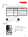
28 Dokumentation
29 Netzkabel (außer bei FESTINSTALLATIONS-Version)
30 Teleskopschienen und Schraubenmaterial für Einbau in 19"-Schränke
Page 12 - 51033211DE/AA
28
2. Aufstellung und Installation
2.2 Einbau des Rack-Modells
Einbau und Befestigung der Teleskopschienen und der Rack.
1
3
3
3
4
3
2
Befestigungsschrauben und Teleskopschienen liegen dem Gerät bei.
51033211DE/AA
- Page 13
2. Aufstellung und Installation
2.3 Anschluß des RS232-Kommunikationskabels (wahlweise)
1. Kommunikationskabel 25 an die serielle Schnittstelle des zu
schützenden Systems anschließen.
2. Kommunikationskabel 25 an die RS232-Schnittstelle 11 der
USV anschließen.
Die USV kann nun über verschiedene Softwarepakete von MGE
UPS SYSTEMS mit dem angeschlossenen Rechnersystem
kommunizieren (Überwachung, Konfiguration,
Sicherheitsparameter).
Anschlußbelegung der USV RS232-Schnittstelle 11 .
RD TD
OV
5
4
9
3 2
8
1
7 6
RTS
2.4 Einbau einer Kommunikationskarte (Option)
Steckplatz für eine Kommunikationskarte.
Die Kommunikationskarte kann bei eingeschalteter USV
installiert werden:
1. Abdeckung an der USV entfernen.
2. Karte in den zugehörigen Steckplatz einstecken.
3. Kartenabdeckung mit 2 Schrauben befestigen.
Page 14 - 51033211DE/AA
2. Aufstellung und Installation
2.5 Montage der Anschlußmodule
Befestigung der Anschlußmodule
1. Anschlußmodul auf den Steckverbinder 10 aufstecken.
10
2. Anschlußmodul mit 2 Schrauben 31 an der USV befestigen.
31
31
Fault tolerant Modul
Vor dem Anschluß ist sicherzustellen, daß der Batterie-Leistungsschalter 8 in OFF-Stellung steht
und das Netzkabel nicht angeschlossen ist.
Anschluß der Verbraucher:
Verbraucher direkt an die Abgangssteckdosen 2 anschließen.
2
1
Netzanschluß:
29
1. Netzkabel 29 an die Gerätesteckdose 1 anschließen.
2. Das andere Ende des Netzkabels 29 mit einer normalen
Netzsteckdose verbinden.
51033211DE/AA
- Page 15
2. Aufstellung und Installation
Hot-Swap Modul
Vor dem Anschluß ist sicherzustellen, daß der Batterie-Leistungsschalter 8 in OFF-Stellung steht
und das Netzkabel nicht angeschlossen ist.
Anschluß der Verbraucher über Abgangssteckdosen:
Verbraucher direkt an die Abgangssteckdosen 2 anschließen.
2
8
32
Anschluß der Verbraucher über Klemmleiste:
Dieser Anschluß darf nur von qualifiziertem Fachpersonal
durchgeführt werden.
1. Klemmenabdeckung 32 entfernen.
2. Verbraucher-Anschlußkabel durch die Kabeleinführung 33
führen.
3. Alle drei Leiter des Kabels an die Ausgangs-Klemmleiste 5
anschließen.
33
Erdungsleiter unbedingt zuerst anschließen.
4. Klemmendeckung wieder anbringen.
5. Mutter der Kabeleinführung 33 anziehen.
5
Kabeldurchmesser und Leiterquerschnitte hängen von der
Nennleistung der USV ab.
Kabeldurchmesser
(mm)
Erdleiter
Leiterquerschnitt
(mm2)
EXtreme 1500 bis 2000
9 bis 12
1 bis 4
EXtreme 2500 bis 3000
9 bis 12
1,5 bis 4
1
29
Page 16 - 51033211DE/AA
Netzanschluß:
1. Netzkabel 29 an die Gerätesteckdose 1 anschließen.
2. Das andere Ende des Netzkabels mit einer Netzsteckdose
verbinden.
2. Aufstellung und Installation
Install Modul
Dieser Anschluß darf nur von qualifiziertem Fachpersonal durchgeführt werden.
Vor dem Anschluß ist sicherzustellen, daß der Batterie-Leistungsschalter 8 in OFF-Stellung steht
und die netzseitigen Schutzorgane ausgeschaltet sind.
8
Kabeldurchmesser und Leiterquerschnitte hängen von der
Nennleistung der USV ab.
Kabeldurchmesser
(mm)
Leiterquerschnitt
(mm2)
EXtreme 1500 bis 2000
9 bis 12
1 bis 4
EXtreme 2500 bis 3000
9 bis 12
1,5 bis 4
32
Netz- und Verbraucheranschluß:
1. Klemmenabdeckung 32 entfernen.
2. Verbraucher- und Netz-Anschlußkabel durch die
Kabeleinführung 33 führen.
3. Alle drei Leiter des Abgangskabels an die AusgangsKlemmleiste 5 anschließen.
Erdungsleiter unbedingt zuerst anschließen.
33
4. Alle drei Leiter des Netzkabels an die Eingangs-Klemmleiste
␣ ␣ 4 anschließen.
5. Klemmenabdeckung wieder anbringen.
6. Mutter der Kabeleinführung 33 anziehen.
Erdleiter
5
4
51033211DE/AA
- Seite 17
3. Betriebszustände
3.1 Betriebsarten
ONLINE-Mode
Diese Betriebsart ist werksseitig voreingestellt. Dabei arbeitet
die USV nach dem Doppelwandlerprinzip.
Es können zwei Betriebszustände vorliegen:
22
LED 22 leuchtet: Das Einspeisenetz ist vorhanden
(Normalbetrieb).
Das Einspeisenetz versorgt über die USV die Verbraucher.
LED 23 leuchtet: Das Einspeisenetz ist nicht vorhanden
(Batteriebetrieb).
Die Batterie versorgt über die USV die Verbraucher .
23
ECO-Mode
Der Hauptvorteil dieser Betriebsart ist ihr geringer Energieverbrauch. Sie ermöglicht die direkte
Verbraucherversorgung über das Netz, solange dessen Kennwerte innerhalb der Toleranzgrenzen liegen.
Die Umschaltung auf den ECO-Mode und die Festlegung der Toleranzgrenzen für die direkte
Netzeinspeisung können über die Software "UPS Driver" (mitgelieferte Diskette 27 ) individuell
festgelegt werden (siehe Abschnitt 3.5).
Es können drei Betriebszustände vorliegen:
21
22
Das Einspeisenetz liegt innerhalb der festgelegten Toleranzen:
Die an die USV angeschlossenen Verbraucher werden über die
automatische Netzrückschalteinrichtung (NRE) direkt aus dem
Netz versorgt, und die LED 21 leuchtet.
Das Einspeisenetz liegt außerhalb der festgelegten Toleranzen:
Die USV schaltet automatisch in den ONLINE-Mode, und die
LED 22 leuchtet.
Das Einspeisenetz ist ausgefallen: Die LED 23 leuchtet, und
die USV arbeitet im Batteriebetrieb.
23
Seite 18 - 51033211DE/AA
3. Betriebszustände
3.2 Inbetriebnahme der USV
Die an die USV angeschlossenen Verbraucher können unabhängig vom Vorhandensein des Einspeisenetzes
eingeschaltet werden.
Vor dem ersten Einschalten der USV ist die Einstellung der Netzspannung zu überprüfen.
Werden die Verbraucher nicht mit 230 V / 50 Hz eingespeist, müssen die entsprechenden USVParameter über die Software "UPS Driver" 27 angepaßt werden (siehe Abschnitt 3.5).
1. Batterie-Leistungsschalter 8 einschalten (Stellung ON).
8
2. EIN/AUS-Taster 24 drücken.
24
Alle angeschlossenen Verbraucher werden versorgt.
Der Summer ertönt, und die LEDs 21 , 22 und 23 leuchten
auf.
Leuchten die Anzeigen 21 , 22 oder 23 nicht auf, oder blinkt eine der LEDs 14 , 15 oder 16 , liegt eine
Störung vor (siehe Abschnitt 4.1).
3.3 Balkenanzeige
Die in einer senkrechten Leiste angeordneten LEDs 14 bis 17 zeigen drei verschiedene Informationen an:
1. Restautonomiezeit der Batterie in %.
14
15
16
17
18
2. Bei Betätigung der Taste 18 : Auslastungsgrad durch die
angeschlossenen Verbraucher in %.
3. Betriebsstörungen (Blinken + Piepton):
14 Überlast
15 interne USV-Störung
16 Batteriestörung
17 Umgebungstemperatur zu hoch
51033211DE/AA
- Seite 19
3. Betriebszustände
3.4 Batterieversorgung der Verbraucher bei Netzausfall
Bei Netzausfall werden die an die USV angeschlossenen Verbraucher unterbrechungsfrei über die Batterie
weiter versorgt.
Umschaltung auf Batteriebetrieb
Das Einspeisenetz liegt außerhalb der zulässigen Toleranzen,
die Anzeige 23 leuchtet auf und der Summer erzeugt 3
Pieptöne.
23
Voralarm "Ende der Autonomiezeit"
Der Alarmgrenzwert kann über die Software "UPS Driver"
kundenspezifisch angepaßt werden (siehe Abschnitt 3.5).
Die LED 23 blinkt.
Der Summer erzeugt alle 3 Sekunden einen Piepton.
23
Die Batterie ist kurz vor dem Entladeende.
Es sollten alle Anwendungen geschlossen werden,
da die Abschaltung der USV kurz bevorsteht.
Abschaltung am Ende der Autonomiezeit
Der Summer erzeugt einen Dauerton.
Zur Unterdrückung des akustischen Alarms, Taste 19 drücken.
19
Die Verbraucher werden NICHT mehr versorgt.
Sleep-Modus
Diese Betriebsart kann über die Software "UPS Driver" (siehe Abschnitt 3.5) individuell eingestellt werden.
Sind keine Verbraucher aufgeschaltet, wird die USV-Anlage bei Batteriebetrieb, abgeschaltet, damit die
Batterie nicht unnötig entladen wird.
Bei Rückkehr des Einspeisenetzes schaltet die USV wieder automatisch auf ONLINE-Mode.
Rückkehr der Netzspannung
Geht die USV trotz Netzrückkehr nicht wieder in den Normalbetrieb über, ist zu überprüfen, ob die Option
"Automatischer Neustart" deaktiviert wurde (siehe Abschnitt 3.5).
Seite 20 - 51033211DE/AA
3. Betriebszustände
3.5 Kundenspezifische Anpassung per Software
Software, Installation und Funktion
Die kundenspezifische Anpassung der USV kann mit Hilfe der Software "UPS Driver" über einen Rechner
erfolgen, der über die serielle Kommunikationsschnittstelle mit der USV verbunden ist (siehe Abschnitt 2.3).
Das RS232-Kommunkationskabel 25 muß angeschlossen und der Batterie-Leistungsschalter 8
eingeschaltet sein.
Installation der Software "UPS Driver":
1. Diskette mit der Aufschrift "UPS Driver" in das Laufwerk des PCs einlegen.
2. Kennbuchstaben für Diskettenlaufwerk eingeben (A :\).
3. Doppelklicken auf "Upsdriv.exe".
Nach Installation der Software "UPS Driver" können Änderungen in einem Dialogfeld mit mehreren
Registerkartes vorgenommen werden.
Registerkarte "Ein/Aus-Bedingungen"
Einstellungen
Default-Einstellung
Automatischer Neustart
Aktiviert
Kaltstart über Batterie
Aktiviert
Zwangsabschaltung
Aktiviert
Sleep-Modus
Deaktiviert
USV-Start/Stop über Software
Aktiviert
51033211DE/AA
- Seite 21
3. Betriebszustände
Registerkarte "Batterie"
Einstellungen
Default-Einstellung
Mögliche Einstellwerte
Zeitintervall für Batterietest
täglich
einmal wöchentlich
einmal monatlich
kein Test
Grenzwert Voralarm "Ende der Autonomiezeit"
20% Restautonomiezeit
40% Restautonomiezeit
Ladegerät
Standard
CLA (2, 4 oder 8 Std.)
Registerkarte "Ausgang"
Nennspannung des Einspeisenetzes (Abb. 1)
230 V
200 V-208 V-220 V-240 V
Nennfrequenz des Einspeisenetzes
50 Hz
60 Hz
Zulässiger Frequenzbereich des Einspeisenetzes (Abb. 2)
± 5%
von ± 1% bis ± 10% in 1%-Schritten
Geschwindigkeit der Frequenzanpassung
Standard
Redundanz (siehe Abschnitt 6.1)
Alarmgrenzwert für Verbraucher-Überlast
100%
von 0 bis 100% in 10%-Schritten
USV-Neustart nach Kurzschluß
Deaktiviert
aktiviert (Optionsfeld anklicken)
Registerkarte "BY-PASS"
Spannungsschwellwert für NRE-Umschaltung bei
USV-Störung oder Überlast
187 V – 265 V
(bei Nennsp. 230 V)
von 187 V bis 265 V
in 1V-Schritten
Zulässige Frequenzabweichung für NREUmschaltung bei inUSV-Störung oder Überlast
± 10%
von ± 1% à ± 10% in 1%-Schritten
Umschaltung auf NRE bei Überlast
Aktiviert
nicht zulässig (Optionsfeld
deaktivieren)
Umschaltung auf NRE bei Störung unabhängig vom
Zustand des Einspeisenetzes
Deaktiviert
aktiviert (Optionsfeld anklicken)
Die Wahl der USV-Nennspannung wirkt sich auf die abgangsseitig verfügbare Leistung aus (siehe Abb. 1).
verfügbare Leistung in % der
Nennleistung
Zulässige Frequenzabweichung für Umschaltung auf NRE
Zulässiger Frequenzbereich
des Einspeisenetzes
Min
Abb. 1
Seite 22 - 51033211DE/AA
Spannung in V
Abb. 2
Max
3. Betriebszustände
Registerkarte "ECO-Mode"
Der ECO-Mode kann nur über die Software "UPS Driver" eingestellt werden.
Einstellungen
Default-Einstellung
Mögliche Einstellwerte
Freigabe des ECO-Mode
keine Freigabe
(unzulässig)
freigegeben
(Optionsfeld anklicken)
Zulässiger Spannungsbereich
für Umschaltung auf ECO-Mode
(siehe Abb. 3)
Zulässiger Einstellbereich des
unteren Spannungsgrenzwerts für
Umschaltung auf ECO-Mode
200 V – 240 V
(bei Nennspannung 230 V)
Oberer Grenzwert zwischen Höchstwert
der Spannung für Umschaltung auf NRE
und Nennspannung.
Unterer Grenzwert zwischen Mindestwert
der Spannung für Umschaltung auf NRE
und Nennspannung.
Zulässiger Einstellbereich des
oberen Spannungsgrenzwerts für
Umschaltung auf ECO-Mode
Spannung in V
Unterer Grenzwert der Spannung
für Umschaltung auf NRE
Nennspannung
Oberer Grenzwert der Spannung für
Umschaltung auf NRE
Abb. 3
3.6 Ausschalten der USV
1. EIN/AUS-Taste 24 drücken (Taste ausgerastet).
Die Verbraucher werden nicht mehr versorgt.
24
2. Batterie-Leistungsschalter 8 ausschalten (Stellung OFF).
Die Batterie wird nicht mehr geladen.
8
51033211DE/AA
- Seite 23
4. Wartung und Service
4.1 Fehlerbehebung
Das Blinken einer der LEDs 14 , 15 , 16 oder 17 zeigt eine Betriebsstörung oder einen Alarmzustand an.
Sobald eine der LEDs blinkt, ist die Balkenanzeige für Autonomiezeit/Auslastungsgrad nicht mehr aktiv.
Fehlerbehebung ohne Inanspruchnahme des MGE Kundendiensts
Fehleranzeige
LED 14 blinkt und Summer
ertönt.
LED 17 blinkt.
Seite 24 - 51033211DE/AA
Fehlerursache
Fehlerbehebung
USV ist überlastet und schaltet bei
Fortdauer der Überlast die
Verbraucherversorgung ab (Dauerton
des Summers).
Leistungsaufnahme der
angeschlossenen Systeme
überprüfen und weniger
wichtige Verbraucher
abschalten.
Umgebungstemperatur liegt über 40 °C.
USV in einem Raum aufstellen,
dessen Umgebungstemperatur
nicht über 40° C liegt.
Die USV kann max. 8 Stunden
bei dieser Übertemperatur
arbeiten.
4. Wartung und Service
Fehlerbehebung, die eine Inanspruchnahme des MGE UPS SYSTEMS Kundendienstes erfordert
Fehleranzeige
LED 15 blinkt und Summer
ertönt.
Fehlerursache
Je nach kundenspezifischer Einstellung
der USV (siehe Abschnitt 3.5) können
zwei Situationen eintreten:
◗ Die Versorgung sämtlicher an die
USV angeschlossenen Systeme bleibt
aufrecht erhalten, erfolgt jedoch über
die automatische NRE (LED 21
leuchtet).
◗ Die Versorgung sämtlicher
angeschlossenen Systeme ist
unterbrochen.
Fehlerbehebung
Bei Hot-Swap- oder Fault
tolerant-Version,
USV austauschen
(siehe Abschnitt 4.2).
Kundendienst benachrichtigen.
Die an die USV
angeschlossenen Systeme
sind nicht mehr geschützt.
LED 16 blinkt.
Batteriestörung bei Batterietest
festgestellt.
Überprüfen, ob BatterieLeistungsschalter 8
eingeschaltet ist.
Falls Schalter eingeschaltet ist,
Kundendienst benachrichtigen
(Batterie defekt oder am Ende
der Lebensdauer).
51033211DE/AA
- Seite 25
4. Wartung und Service
4.2 Austausch der USV
Fault tolerant-Version
Vor dem Austausch muß die Energieversorgung der Verbraucher abgeschaltet werden.
24
8
Vorhandene USV abklemmen:
1. USV durch Betätigung der EIN/AUS-Taste 24 ausschalten
(Taste ausgerastet).
2. Batterie-Leistungsschalter 8 ausschalten.
3. Anschlußmodul durch Herausdrehen der 2 Schrauben 31
von der USV lösen.
Wiederanschluß der neuen USV:
1. Anschlußmodul auf den Steckverbinder 10 stecken und mit 2
Schrauben 31 befestigen.
2. Batterie-Leistungsschalter 8 einschalten.
Aktuelle USV-Einstellungen auf Übereinstimmung
mit den Lastparametern überprüfen
(siehe Abschnitt 3.5).
10
3. USV durch Betätigung der EIN/AUS-Taste 24 wieder
einschalten (Taste eingerastet).
31
Die Verbraucher sind wieder durch die USV geschützt.
31
Seite 26 - 51033211DE/AA
4. Wartung und Service
Hot-Swap- und Install-Version
Vorhandene USV abkemmen:
1. Handumgehung 3 von der Stellung "NORMAL" auf die
Zwischenstellung schalten.
2. Vor dem Umschalten in die Stellung "BY-PASS" prüfen, ob
LED 21 leuchtet.
Vor Umschaltung,
Hinweis! beachten!
NORMAL
BY-PASS
20
21
Vor Umschaltung,
Hinweis! beachten!
NORMAL
BY-PASS
Falls die LED 21 NICHT leuchtet, Handumgehung
NICHT in die Stellung "BY-PASS" umschalten und
Kundendienst benachrichtigen.
3. Handumgehung 3 von der Zwischenstellung in die Stellung
"BY-PASS" umschalten.
Die Stromversorgung der Verbraucher erfolgt aus dem
Einspeisenetz über die Handumgehung.
4. USV durch Betätigung der EIN/AUS-Taste 24 ausschalten
(Taste ausgerastet).
5. Batterie-Leistungsschalter 8 ausschalten.
6. Anschlußmodul durch Herausdrehen der 2 Schrauben 31
von der USV lösen.
Die USV kann nun ausgetauscht werden, die
Verbraucherversorgung erfolgt direkt aus dem
Einspeisenetz.
Wiederanschluß der neuen USV:
1. Anschlußmodul auf den Steckverbinder 10 stecken und mit 2
Schrauben 31 befestigen.
2. Batterie-Leistungsschalter 8 einschalten.
24
8
10
31
31
Aktuelle USV-Einstellungen auf Übereinstimmung
mit den Lastparametern überprüfen
(siehe Abschnitt 3.5).
3. USV durch Betätigung der EIN/AUS-Taste 24 einschalten
(Taste eingerastet).
4. Vor dem Umschalten der Handumgehung von der Stellung
"BY-PASS" in die Zwischenstellung prüfen ob LED 20 leuchtet.
Falls die Anzeige 20 NICHT aufleuchtet,
Handumgehung NICHT umschalten und
Kundendienst benachrichtigen.
5. Handumgehung 3 von der Stellung "BY-PASS" in die
Zwischenstellung umschalten ob LED 21 leuchtet.
6. Handumgehung 3 von der Zwischenstellung auf Stellung
"NORMAL" umschalten.
Die Verbraucher sind wieder durch die USV geschützt.
51033211DE/AA
- Seite 27
5. Umweltschutz
Das vorliegende Produkt wurde im Hinblick auf seine Umweltverträglichkeit entwickelt:
Es enthält weder FKW- noch FCKW-Verbindungen.
Seine Herstellung erfolgte in einer Produktionsstätte gemäß ISO 14001.
Recycling der USV nach Ablauf der Lebensdauer:
MGE UPS SYSTEMS verpflichtet sich, sämtliche nach Ablauf der Lebensdauer rückgeführten Komponenten
durch zugelassene Entsorgungsunternehmen einer Wiederverwertung gemäß den gesetzlichen
Bestimmungen zuzuführen (wenden Sie sich bitte an Ihre MGE-Vertretung).
Verpackung:
Verpackungsmaterial muß gemäß den gesetzlichen Bestimmungen entsorgt werden.
Hinweis:
Dieses Produkt enthält Bleibatterien. Blei kann die Umwelt schädigen wenn es nicht, gemäß den gesetzlichen
Vorschriften, durch Spezialunternehmen entsorgt wird.
Web-Site : www.mgeups.com
Seite 28 - 51033211DE/AA
6. Anhang
6.1 Fachbegriffe
Anschlußmodul
Modul mit netz- und lastseitigen Anschlüssen.
Auslastungsgrad
Verhältnis der durch die angeschlossenen Verbraucher aufgenommenen
Leistung zur verfügbaren USV-Nennleistung.
Ausrüstungen
An die USV angeschlossene Geräte und Verbraucher.
Automatische Netzrückschalteinrichtung
Über die USV gesteuerter, automatischer Umschalter zur direkten
Verbraucherversorgung aus dem Einspeisenetz.
Automatischer Neustart
Wahlweise Freigabe des automatischen Wiederanlaufs der USV bei
Netzrückkehr nach Abschaltung am Ende der Autonomiezeit.
Autonomiezeit
Nutzbare Batteriekapazität.
Balkenanzeige
LED-Leiste am Bedienfeld zur Anzeige des Auslastungsgrades oder der
Restautonomiezeit.
Batterietest
Interne Überprüfung der Batterie zur Feststellung des Zustandes.
CLA Hochleistungsladegerät
Spezielles Ladegerät mit hoher Kapazität zur Aufladung von BatterieErweiterungsmodulen für sehr lange Autonomiezeiten.
Doppelwandlerprinzip
Die Netzspannung wird permanent in der USV gleichgerichtet und
anschließend wieder in eine saubere Wechselspannung umgewandelt.
ECO-Mode
Betriebsart zur direkten Verbraucherversorgung über das Netz, wenn dessen
Kennwerte innerhalb der kundenspezifischen Toleranzgrenzen liegen. Durch
diese Betriebsart läßt sich eine Energieeinsparung erzielen.
Fault tolerant
USV-Version bzw. Anschlußmodul ohne Handumgehung für Netz- und
Verbraucheranschluß über Steckdosen.
Geschwindigkeit der Frequenzanpassung
Geschwindigkeit der Frequenzsynchronisation zwischen USV und
Einspeisenetz.
1. Bei Anschluß einer USV wird für die Einstellung der
Synchronisationsgeschwindigkeit die Option "Standard" gewählt.
2. Bei Anschluß von zwei USV in sequentieller Redundanz wird die erste USV
über das Netz, die zweite USV über die erste und die Last über die zweite
USV eingespeist. Die Geschwindigkeit der Frequenzsynchronisation muß für
die erste USV auf "Standard" und für die zweite USV auf "Redundanz"
eingestellt sein.
Handumgehung
Vom Anwender manuell zu betätigender Drehschalter zur direkten
Verbraucherversorgung aus dem Einspeisenetz. Die Umschaltung auf die
Handumgehung erlaubt die Wartung oder den Austausch der USV ohne
Betriebsunterbrechung.
51033211DE/AA
- Seite 29
6. Anhang
Hot Swap
USV-Version bzw. Anschlußmodul mit Handumgehung für Netz- und
Verbraucheranschluß über Steckdose.
Install
USV-Version bzw. Anschlußmodul mit Handumgehung für Netz- und
Verbraucheranschluß über Anschlußklemmen.
Kaltstart
Siehe "Start im Batteriebetrieb".
Kundenspezifische Anpassung
Bestimmte USV-Funktionen können über die Software "UPS Driver" an
individuelle Kundenbedürfnisse angepaßt werden.
Registerkarte
Bildschirmdarstellung einer Software zur Auswahl bestimmter Optionen.
NRE
siehe "Automatische Netzrückschalteinrichtung".
ONLINE-Mode
Normale Betriebsart, in der die USV im Doppelwandlerprinzip die Verbraucher
versorgt.
Redundanz
Siehe "Geschwindigkeit der Frequenzanpassung".
Sleep-Mode
Abschaltung der USV im Batteriebetrieb, wenn verbraucherseitig keine
Leistungsentnahme erfolgt.
Spannungsschwellwerte für NRE-Umschaltung bei interner USV-Störung oder Überlast
Spannungsgrenzwerte (Min./Max.) für die automatische Umschaltung auf die
NRE bei interner USV-Störung oder Überlast.
Start im Batteriebetrieb
Aufschalten der an die USV angeschlossenen Verbraucher ohne
Vorhandensein des Einspeisenetzes (Stromversorgung ausschließlich aus der
Batterie).
USV
Unterbrechungsfreie Stromversorgung.
USV-Start/Stop über Software
Aktivierung/Deaktivierung von Start/Stop-Bedingungen für die USV über die
USV-Managementsoftware der angeschlossenen Rechnersysteme.
Zulässiger Frequenzbereich des Einspeisenetzes
Frequenzwerte des Einspeisenetzes, für die der ONLINE-Mode der USV
zulässig ist (Doppelwandlerprinzip).
Zulässiger Nennspannungsbereich für Umschaltung auf ECO-Mode
Netzspannungswerte, bei denen die USV im ECO-Mode arbeitet. Die
Versorgung der an die USV angeschlossenen Systeme erfolgt dabei über die
automatische Netzrückschalteinrichtung direkt vom Netz.
Zwangsabschaltung
Seite 30 - 51033211DE/AA
Abschaltung der Stromversorgung der Verbraucher (10s) nach einem System
Shutdown selbst bei Rückkehr des Einspeisenetzes .
6. Anhang
6.2 Stichwortregister
A
Alarmton (Summer) ..................................... 4-10-20
Anschlüsse
Anschlußmodul ........................................ 16-17
Kommunikationskarte .................................... 14
RS232-Kommunikationsschnittstelle ............. 14
Ausschalten der USV ...................................... 10-23
Ausschalten der USV über Software ................... 21
Automatische Netzrückschalteinrichtung (NRE)
................................................................. 18-25
Automatischer Neustart ....................................... 21
I
B
N
Balkenanzeige ..................................................... 19
Batterie
Voralarm "Ende der Autonomiezeit" .............. 20
Batteriefehler ............................................ 10-19
Ende der Autonomiezeit ................................ 20
Recycling ....................................................... 28
Test der Autonomiezeit ................................. 22
Umschaltung auf Batteriebetrieb ................... 20
NRE ................................................................. 18-25
E
S
ECO-Mode ................................................ 10-18-23
Freigabe/keine Freigabe ............................... 23
Zulässiger Spannungsbereich ....................... 23
Einbau des Rack-Modells .................................... 13
Einschalten der USV ............................................ 19
Automatischer Neustart ................................. 21
Einspeisenetz
Frequenzbereich ........................................... 22
Nennfrequenz ................................................ 22
Nennspannung .............................................. 22
Netzausfall ..................................................... 20
Netzrückkehr ........................................................ 20
T
F
Fault tolerant ............................................... 8-15-26
Festinstallation ............................................ 8-17-27
Install ........................................................... 8-17-27
K
Kommunikation .................................................... 14
Kundenspezifische Anpassung ............................ 21
Ausgang ........................................................ 22
Batterie .......................................................... 22
ECO-Mode .................................................... 23
Ein/Aus-Bedingungen ................................... 21
O
ON LINE-Mode ..................................... 10-18-25-30
R
Rack-Modell ...................................................... 7-13
Sicherheit ............................................................... 3
Sleep-Mode ..................................................... 20-21
Störung der USV ............................................. 10-19
Automatische Umschaltung auf NRE-Zweig
...................................................................... 25
Test der Leuchtanzeigen ..................................... 10
Tower-Modell .................................................... 7-11
U
Überlast ..................................................... 10-22-24
Umgebungstemperatur zu hoch ................ 10-19-24
UPS Driver ................................................ 11-12-21
Z
H
Zwangsabschaltung ............................................. 21
Handumgehung .............................................. 10-26
Hot Swap ..................................................... 8-16-27
51033211DE/AA
- Seite 31
140, Avenue Jean Kuntzmann
ZIRST - Montbonnot St Martin
38334 - ST ISMIER CEDEX - FRANCE
www.mgeups.com
51033211DE/AA
Seite 32 - 51033211DE/AA
Nichts hält Sie mehr auf Verantwortlich
Publication : MGE UPS SYSTEMS, 10/99.
MGE UPS SYSTEMS