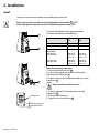
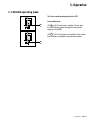
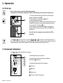
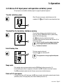
1
www.mgeups.com
MGE UPS SYSTEMS
Pulsar EXtreme
2000/3000 VA
Installation and user
manual
P
P
O
W
E
D E R
V I
R O
R
T H E
U N
I N
T E
R
R
U
P
T
I
B
L
E
51033211EN/AC
- Page 1
Introduction
Thank you for selecting an MGE UPS SYSTEMS product to protect your electrical equipment.
The Pulsar EXtreme range has been designed with the utmost care. We recommend that you take the time
to read this manual to take full advantage of the many features of your UPS.
MGE UPS SYSTEMS pays great attention to the environmental impact of its products. Measures that have
made Pulsar EXtreme a reference in environmental protection include:
◗ Production in an ISO 14001 certified factory,
◗ Recycling of Pulsar EXtreme at the end of its service life.
To discover the entire range of MGE UPS SYSTEMS products and the options available for the Pulsar
EXtreme range:
◗ We invite you to visit our Web site at www.mgeups.com
(page: www.mgeups.com/products/pdt230/smallups/extreme/extrem10.htm),
◗ Or contact your MGE UPS SYSTEMS representative.
Page 2 - 51033211EN/AC
Foreword
Using this document
Information may be found primarily by consulting:
◗ The contents,
◗ The index.
Pictograms
Important instructions that must always be followed.
Information, advice, help.
Visual indication.
Action.
Audio indication.
In the illustrations on the following pages, the symbols below are used:
LED off.
LED on.
LED flashing.
51033211EN/AC
- Page 3
Contents
1.
Presentation
1.1
Pulsar EXtreme range ................................................................................................................. 7
Tower model .................................................................................................................................... 7
Rack model ..................................................................................................................................... 7
1.2
Connection modules ................................................................................................................... 8
Fault tolerant ................................................................................................................................... 8
Hot swap ......................................................................................................................................... 8
Install ............................................................................................................................................... 8
1.3
Back ............................................................................................................................................. 9
1.4
Options .......................................................................................................................................... 9
Transformer for galvanic isolation or earthing arrangement change .............................................. 9
Battery extensions for UPS backup times of 66 minutes ................................................................ 9
CLA module (Long backup time charger) for backup times of 2 to 8 hours .................................. 10
1.5
2.
Control panel ............................................................................................................................... 10
Installation
2.1
Unpacking and checks ............................................................................................................... 12
"Tower" model ............................................................................................................................... 12
"Rack" model ................................................................................................................................ 13
2.2
Installation of the rack version .................................................................................................. 14
2.3
Connection to the RS 232 communications port (optional) ................................................... 15
2.4
Installation of the communications-card option ...................................................................... 15
2.5
Securing and connecting the connection modules ................................................................. 16
Securing the connection modules ................................................................................................. 16
Fault tolerant ................................................................................................................................. 16
Hot swap ....................................................................................................................................... 17
Install ............................................................................................................................................. 18
3.
Page 4 - 51033211EN/AC
Operation
3.1
ON-LINE operating mode ........................................................................................................... 19
3.2
Start-up ........................................................................................................................................ 20
3.3
Bargraph indications .................................................................................................................. 20
Contents
3.4
Failure of AC input power and operation on battery power .................................................... 21
Transfer to battery power .............................................................................................................. 21
Threshold for the low-battery shutdown warning .......................................................................... 21
End of backup time ....................................................................................................................... 21
Sleep mode ................................................................................................................................... 21
Return of AC input power .............................................................................................................. 21
3.5
Personalization ........................................................................................................................... 22
Function ........................................................................................................................................ 22
"ON / OFF conditions" tab ............................................................................................................. 22
"Battery" tab .................................................................................................................................. 23
"Output" tab ................................................................................................................................... 23
"By-pass" tab ................................................................................................................................ 23
3.6
Shutdown ..................................................................................................................................... 24
Shutdown of connected equipment ............................................................................................... 24
Complete shutdown of the UPS .................................................................................................... 24
4.
Maintenance
4.1
4.2
Troubleshooting .......................................................................................................................... 25
UPS replacement ........................................................................................................................ 27
Fault-tolerant connection module .................................................................................................. 27
Hot-swap and Install connection modules .................................................................................... 28
5.
6.
Environment ..................................................................................................................................... 30
Appendices
6.1
Glossary ....................................................................................................................................... 31
6.2
Index ............................................................................................................................................. 33
51033211EN/AC
- Page 5
1. Presentation
1.1 Pulsar EXtreme range
Tower model
Dimensions in mm
(H x W x D)
EXtreme 2000 - 3000
443 x 173 x 465
Weight in kg
Pulsar EXtreme 2000
29
Pulsar EXtreme 3000
36
Rack model
Dimensions in mm
(H x W x D)
EXtreme 2000 - 3000
177 (4U) x 483 x 462
Weight in kg
Page 6 - 51033211EN/AC
Pulsar EXtreme 2000
31
Pulsar EXtreme 3000
38
1. Presentation
1.2 Connection modules
Fault tolerant
1 Socket for connection to AC-power source.
2 Outlets for direct connection to protected equipment.
3 Manual bypass switch.
1
2
4 Input terminal block with cable clamp.
5 Output terminal block with cable clamp.
Hot swap
Different types of sockets available on Fault tolerant and Hot swap
connection modules:
AC input cord
Outlet sockets
Power cords to
equipment
3
1
USE
DIN plug,
2.5m cable,
IEC320C20 cable
4 USE outlets (16A)
5
DIN
DIN plug,
2.5m cable,
IEC320C20 cable
4 DIN outlets (16A)
BS
BS plug,
2.5m cable,
IEC320C20 cable
4 BS outlets (13A)
IEC
IEC320C20 plug
(not supplied)
4 IEC320C13 outlets
(10A) protected by
10A circuit breaker
and 1 IEC320C20
outlet (16A)
NEMA
NEMA plug,
2.5m cable,
IEC320C20 cable
4 NEMA outlets
(15A / 250V)
2
Install
3
SWITZERLAND Swiss plug,
2.5m cable,
IEC320C20 cable
5
4
AUSTRALIA
4 IEC320C13 outlets
(10A) protected by
10A circuit breaker
and 1 IEC320C20
outlet (16A)
2x
IEC320C13 plug,
2.5m cable,
IEC320C13 plug
2x
IEC320C13 plug,
2.5m cable,
IEC320C13 plug
AUSTRALIAN plug, 4 AUSTRALIAN
2.5m cable,
outlets (16A)
IEC320C20 cable
51033211EN/AC
- Page 7
1. Presentation
1.3 Back
Page 8 - 51033211EN/AC
6
Slot for communications-card option.
7
Battery module connector.
8
Battery circuit breaker.
9
Rating plate.
10
Connector for connection modules.
11
RS232 communications port.
1. Presentation
1.4 Options
Transformer for galvanic isolation or earthing arrangement change
Pulsar EXtreme Transformer
Nominal power
3 kVA
16 A
Nominal current
Input voltage
230V (+15%, -20%)
< 3%
Voltage drop
Frequency
50/60 Hz (+/-10%)
3.75 kV / 5 M ohms
Isolation (EN 61558-1-2-4)
Operating temperature
Max. operating rel. humidity
From 0° to +40°C
95%
Derating / altitude
Natural ventilation
Pn-10% > 1000 m
IP20 ANAN
Dimensions HxWxD (tower)
Dimensions HxWxD (rack 4U)
443 x 173 x 465 mm
177 x 483 x 462 mm
Weight (tower)
Weight (rack)
24 kg
28 kg
Important: to simplify installation, connect the Pulsar EXtreme Transformer downsteam of the UPSs.
Visit our Web site: www.mgeups.com/products/pdt230/smallups/extreme/transfo.htm
Battery extensions for UPS backup times of 66 minutes
Battery extensions for Pulsar EXtreme:
Pulsar EXtreme
9 min
Pulsar
Pulsar
Pulsar
Pulsar
EXtreme
+ EXtreme
+ EXtreme
+ EXtreme
EXB
EXB
EXB
EXB
20 min
36 min
Pulsar EXtreme offers a standard
backup time of 9 minutes.
To increase backup time, it is possible
to connect Pulsar EXtreme EXB
modules to the UPSs.
Visit our Web site: www.mgeups.com/
products/pdt230/smallups/extreme/
guide.htm.
66 min
The Pulsar EXtreme EXB modules are available in "tower" and in "rack" models.
The Pulsar EXtreme EXB modules come with their connection cables.
51033211EN/AC
- Page 9
1. Presentation
CLA module (Long backup time charger) for backup times of 2 to 8 hours
Very long backup times, from 2 to 8 hours at full load, require a Pulsar EXtreme CLA module (2000VA or
3000VA).
Visit our Web site: www.mgeups.com/products/pdt230/smallups/extreme/cla/cla2.htm.
Pulsar
EXtreme
25A
5Ah
12V-6
Pulsar
EXtreme
CLA
1
1
5Ah
12V-6
6
9
2
2
5Ah
12V-6
h
5A
12V-6
5Ah
1
1
5Ah
12V-6
5Ah
12V-6
VA
2000 A
V
3000
5Ah
12V-6
5Ah
12V-6
5Ah
12V-6
5Ah
12V-6
7
10
6
9
2
2
12V-6
5Ah
12V-6
2h
Page 10 - 51033211EN/AC
VA
2000 A
V
3000
7
10
5Ah
12V-6
1
1
5Ah
12V-6
4h
6
9
2
2
5Ah
12V-6
5Ah
12V-6
5Ah
12V-6
5Ah
12V-6
5Ah
12V-6
5Ah
12V-6
5Ah
12V-6
5Ah
12V-6
8h
VA
2000 A
V
3000
7
10
5Ah
12V-6
5Ah
12V-6
5Ah
12V-6
1. Presentation
1.5 Control panel
bypass
Alarms
% battery
remaining
% load
14
UPS overload
100%
100%
15
Electronics fault
80%
80%
16
Battery fault
50%
50%
17
Ambient temp.
> 40°C
20%
20%
18
Hold down to display
percent load.
19
Lamp test or buzzer OFF.
20
Operation on manual bypass.
21
Operation on automatic bypass.
22
Operation in ON-LINE mode.
23
Operation on battery power.
24
ON/OFF.
51033211EN/AC
- Page 11
2. Installation
2.1 Unpacking and checks
Tower model
29
27
25
26
28
25 RS 232 communications cable.
26 CD ROM with "Solution Pac" and "UPS Driver" softwares.
27 Quick Start documentation.
28 Installation and user manual.
29 Electrical power cord (except INSTALL version and version with IEC outlets).
Page 12 - 51033211EN/AC
2. Installation
Rack model
30
29
27
25
26
28
25 RS 232 communications cable.
26 CD ROM with "Solution Pac" and "UPS Driver" softwares.
27 Quick Start documentation.
28 Installation and user manual.
29 Electrical power cord (except INSTALL version and version with IEC outlets).
30 Telescopic rails for mounting in 19" bay with mounting hardware.
51033211EN/AC
- Page 13
2. Installation
2.2 Installation of the rack version
Rack mounting diagram with rails.
1
3
3
3
4
3
2
The rails and the necessary mounting hardware are supplied with the UPS in the package.
Page 14 - 51033211EN/AC
2. Installation
2.3 Connection to the RS 232 communications port (optional)
11
1. Connect the RS 232 communications cable 25 to the serial
port on the computer.
2. Connect the RS 232 communications cable 25 to the RS 232
communications port 11 on the UPS.
25
The UPS can now communicate with all MGE UPS SYSTEMS
supervision, set-up or safety software.
Pin-out diagram for the RS 232 communications port 11
on the UPS.
RD TD
OV
5
4
9
3 2
8
1
7 6
RTS
2.4 Installation of the communications-card option
Slot for the communications-card option.
It is not necessary to shut down the UPS to install
the communications card:
1. Remove the slot cover.
2. Insert the card in the slot.
3. Secure the card with the two screws.
51033211EN/AC
- Page 15
2. Installation
2.5 Securing and connecting the connection modules
Securing the connection modules
1. Insert the connection module in the connector 10 .
10
2. Secure the connection module to the UPS using
the two screws 31 .
31
31
Fault tolerant
Before carrying out any connections, check that the battery circuit breaker 8 is OFF and that the
electrical power cord to the AC-power source is disconnected.
Connection of equipment:
Connect the protected equipment directly to the outlets 2 .
2
1
Connection to the AC-power source:
29
1. Connect the electrical power cord 29 to the socket 1
for connection to AC-power source.
2. Connect the other end of the electrical power cord
to an AC-power outlet.
Page 16 - 51033211EN/AC
2. Installation
Hot swap
Before carrying out any connections, check that the battery circuit breaker 8 is OFF
and that the electrical power cord to the AC-power source is disconnected.
Connection of equipment to outlets
Plug your equipment into the outlets 2 .
2
Connection of equipment to a terminal block:
This type of connection must be carried out by qualified
electrical personnel.
1. Remove the terminal-block cover 32 .
2. Insert the cable supplying the equipment through the cable
clamp 33 .
3. Connect the three wires to the output terminal block 5 .
8
32
Always connect the earthing wire first.
4. Remove the terminal-block cover.
5. Tighten the nut on the cable clamp 33 .
The overall cable diameter and the cross-sectional area
of the three wires depends on the UPS rating.
33
Pulsar EXtreme
2000
5
Output terminal block
Phase
Neutral
Earthing wire
1
29
Pulsar EXtreme
3000
Cable diameter
From 9 to 12 mm
From 9 to 12 mm
Cross-sectional area of each wire
1 to 4 mm2
1,5 to 4 mm2
C60N 10A 2P
(maximum line
current = 9A)
C60N 16A 2P
(maximum line
current = 13A)
C60N 16A 2P
(maximum line
current = 11A)
C60N 20A 2P
(maximum line
current = 16A)
Recommended upstream
circuit breaker
◗ Nominal rating
(47 to 63Hz, 230V)
◗ Maximum rating
(47 to 63Hz, 187V)
Connection to the AC-power source:
1. Connect the electrical power cord 29 to the socket 1
for connection to AC-power source.
2. Connect the other end of the electrical power cord
to an AC-power outlet.
51033211EN/AC
- Page 17
2. Installation
Install
This type of connection must be carried out by qualified electrical personnel.
Before carrying out any connections, check that the battery circuit breaker 8 is OFF
and that the upstream protection devices (AC distribution system) are open (OFF).
8
The overall cable diameter and the cross-sectional area
of the three wires depends on the UPS rating.
Cable diameter
Cross-sectional area of each wire
32
Recommended upstream
circuit breaker
◗ Nominal rating
(47 to 63Hz, 230V)
◗ Maximum rating
(47 to 63Hz, 187V)
33
Pulsar EXtreme
2000
Pulsar EXtreme
3000
From 9 to 12 mm
From 9 to 12 mm
1 to 4 mm
2
1,5 to 4 mm2
C60N 10A 2P
(maximum line
current = 9A)
C60N 16A 2P
(maximum line
current = 13A)
C60N 16A 2P
(maximum line
current = 11A)
C60N 20A 2P
(maximum line
current = 16A)
Power and equipment connections:
1. Remove the terminal-block cover 32 .
2. Insert the cable supplying the equipment and the power
cable through the cable clamps 33 .
3. Connect the three wires of the equipment cable to the output
terminal block 5 .
Always connect the earthing wire first.
Earthing wires
Page 18 - 51033211EN/AC
5
Output terminal block
4
Input terminal block
4. Connect the three wires of the power cable to the input
terminal block 4 .
5. Refit the terminal-block cover.
6. Tighten the nut on the cable clamp 33 .
3. Operation
3.1 ON-LINE operating mode
This is the normal operating mode for the UPS.
bypass
Two possible cases:
22
LED 22 is ON: AC input power is available. Power is drawn
from the distribution system and supplied to the protected
equipment via the UPS.
LED 23 is ON: AC input power is not available. Power is drawn
from the battery and supplied to the protected equipment.
bypass
23
51033211EN/AC
- Page 19
3. Operation
3.2 Start-up
Prior to initial start-up, check the UPS voltage settings.
The frequency of the output voltage (50 or 60 Hz) is automatically set to that of the input source.
8
24
1. Close the upstream device (ON position) controlling the
supply of AC power to the UPS.
2. Set the battery circuit breaker(s) 8 to ON.
The buzzer beeps three times.
If the supply frequency is different than the default value set on
the UPS, the new value is set and the buzzer beeps 4 times.
3. Press the ON / OFF button 24 .
All the equipment connected to the UPS is now energised,
however it takes another 30 seconds before the UPS is fully
operational.
After this time, the equipment connected to the UPS is
protected.
If LED 22 or 23 do not go ON or if one of LED 14 , 15 , 16 or 17 flash, there is a fault (see section 4.1).
In order to detect any wiring errors, it is essential that the AC-power source be present at the first switch-on.
Subsequently, the device may be switched-on without the presence of the AC-power source.
◗
◗
3.3 Bargraph indications
LEDs 14 to 17 provide three different indications.
1. Remaining backup time in percent.
14
15
2. Percent load drawn by the protected equipment,
when button 18 is pressed.
16
17
18
3. Operating faults (flashing LED and beeps):
14 Overload.
15 UPS fault.
16 Battery fault.
17 Excessive ambient temperature.
Page 20 - 51033211EN/AC
3. Operation
3.4 Failure of AC input power and operation on battery power
AC input power is not available, the battery steps in to supply the protected equipment.
Transfer to battery power
When AC-power source goes outside tolerances or fails
completely, LED 23 goes ON and the buzzer beeps three times.
bypass
23
Threshold for the low-battery shutdown warning
bypass
23
The low-battery shutdown warning threshold can be set
by the user, with the "UPS Driver" software (default setting
equal to 20% of full backup time).
LED 23 flashes when the setted level is reached.
The buzzer beeps every three seconds when less than 10% of
backup time remains.
There is very little remaining battery backup time.
Close all applications because UPS automatic
shutdown is imminent.
End of backup time
The buzzer sounds continuously.
Press button 19 to turn the buzzer OFF.
19
The equipment is no longer supplied with power.
Sleep mode
This operating mode may be personalized using the "UPS Driver" software (see section 3.5).
It saves battery power when no equipment is connected to the UPS. Shutdown occurs after 5 minutes.
The UPS automatically restarts when the AC-power source returns to within tolerances.
Return of AC input power
If, in spite of the return of AC input power, the UPS does not restart, check that the automatic-restart function
(activated by return of AC input power) has not been disabled (see section 3.5).
51033211EN/AC
- Page 21
3. Operation
3.5 Personalization
Function
Personalization parameters can be set and modified using the "UPS Driver" software installed on a computer
that is connected to the UPS (see section 2.3 Connection to the RS 232 communications port).
Check that the RS 232 cable 25 is correctly connected and that the battery circuit breaker 8
is closed.
"UPS Driver" installation:
1 - Insert the Solution-Pac CD-ROM containing the UPS Driver software in the drive of a PC running
Windows.
2 - Open the Windows File manager or Explorer and select the CD-ROM drive.
3 - Double-click "\Emb\Index.htm", then "UPS Driver".
Once "UPS Driver" has been installed, UPS parameters can be modified in a window containing
a number of tabs, each presenting a set of parameters.
"ON / OFF conditions" tab
Page 22 - 51033211EN/AC
Personalizable function
Default setting
Automatic start
Enabled
Cold start (battery power)
Enabled
Forced shutdown
Enabled
Sleep mode
Disabled
UPS ON / OFF via software
Enabled
3. Operation
"Battery" tab
Personalizable function
Default setting
Options
"Battery test" intervals
Every day
Once a week
Once a month
No test
"Low-battery shutdown warning" threshold
20% remaining battery
backup time
40% remaining battery
backup time
Charger
Standard
CLA (2, 4 or 8 hours)
"Output" tab
Rated AC-power source voltage (see figure 1)
230 V
200 V-208 V-220 V-240 V
Rated AC-power source frequency
50 Hz
60 Hz
Tolerance for AC-power source frequency
± 5%
± 1% to ± 10% , in 1% steps
Overload alarm level
100%
0 to 100%, in 10% steps
UPS restart after a short-circuit
Disabled
Enabled (click to add check)
187 V to 265 V (for
230 V rated voltage)
187 V to 265 V,
in 1V steps
Authorized frequency range for transfer to bypass
if fault or overload
± 10%
± 1% to ± 10%, in 1% steps
Transfer to bypass if overload
Enabled
Disabled (click to remove check)
Transfer to bypass following a fault, whatever
the conditions on the AC-power source
Disabled
Enabled (click to add check)
"By-pass" tab
Authorized voltage range for transfer to bypass
if fault or overload
The value selected for the rated UPS voltage impacts on the power available at UPS output
(see the diagram below).
100%
95%
90%
Available power as a percentage
of the rated power
66%
50%
Voltage in V
84
Fig. 1
51033211EN/AC
- Page 23
3. Operation
3.6 Shutdown
Shutdown of connected equipment
1. Press button 24 (return to the OFF position).
21
The connected equipment is no longer supplied with power,
but the battery is maintened charged if AC-power source is
present.
If the AC source fails, even though the connected
equipment is no longer supplied, the UPS operates on
battery power and therefore reduces the available
backup time.
Complete shutdown of the UPS
1. Press button 24 (return to the OFF position).
The connected equipment is no longer supplied with power.
8
2. Open the upstream device (OFF position) controlling the
supply of AC power to the UPS.
3. Switch the battery circuit breaker(s) 8 to OFF position.
The UPS is now de-energised and the batteries are
no longer recharged.
Warning: if the upstream source is not switched off, the UPS
remains in operation.
Page 24 - 51033211EN/AC
4. Maintenance
4.1 Troubleshooting
If one or more LEDs 14 , 15 , 16 or 17 flash, there is a operating anomaly or an alarm.
If a LED flashes, the bargraph data is no longer displayed.
Troubleshooting not requiring MGE after-sales support
Indication
Signification
Correction
LEDs 14, 15 , 16 , 17
flash and the buzzer
beeps.
The UPS has detected a problem
concerning the wiring of the
connection module input.
Shut down the UPS and check that the
input power cable is properly connected to
the input terminal block and the load to the
output terminal block (see p. 18).
After correcting any wiring errors, restart
the UPS as indicated on page 20. If the
problem persists, call MGE after-sales
support.
LED 14 flashes and
the buzzer beeps.
UPS overload. Overload is too long
or too high. The UPS cuts the supply
of power to the connected equipment
and the buzzer beeps continuously.
Check the power drawn by the equipment
and disconnect any non-priority devices.
LED 17 flashes.
Install the UPS in a room where the
The ambient temperature is higher
ambient temperature is not greater than
than 35° C.
35° C.
The UPS is not designed to
operate more than eight
hours under these conditions.
LED 20 is ON.
The UPS is in maintenance mode
(manual bypass)
See point 3 to 6 of in the "Hot-swap and
Install connection modules" part of section
4.2.
51033211EN/AC
- Page 25
4. Maintenance
Troubleshooting requiring MGE after-sales support
Indication
Signification
LED 15 flashes and the buzzer
beeps.
UPS electronics have detected a UPS
fault.
Depending on the UPS personalization
parameters (see section 3.5), there are
two possibilities:
◗ the equipment connected to the UPS
continues to be supplied, but directly
from the AC-power source (via the
automatic bypass for a maximum of 8
hours (LED 21 ON);
◗ the connected equipment is no longer
supplied.
Correction
For UPSs equipped with Hot
swap or Install connection
modules, follow the UPS
replacement procedure (see
section 4.2).
Call the after-sales support
department.
The equipment connected to
the UPS is no longer protected.
LED 16 flashes.
Page 26 - 51033211EN/AC
A battery fault was detected during the
battery test.
Call the after-sales support
department because the
batteries need replacing.
4. Maintenance
4.2 UPS replacement
Fault-tolerant connection module
Before carrying out this operation, the supply of power to the connected equipment must be cut.
The equipment will therefore no longer be powered.
Disconnection:
24
1. Shut down the UPS by pressing button 24 (return to the OFF
position).
2. Open the battery circuit breaker(s) 8 .
3. Open the upstream device (OFF position) controlling the
supply of AC power to the UPS.
4. Remove the two fixing screws 31 and the connection module
from the UPS.
Reconnection:
8
10
31
1. Insert the connection module in the connector 10 and secure
using the two screws 31 .
2. Close the upstream device (ON position) controlling the
supply of AC power to the UPS.
3. Close the battery circuit breaker(s) 8 .
Check that UPS personalization settings still
correspond to the equipment to be supplied
(see section 3.5).
4. Start the UPS by pressing button 24 .
The connected equipment is again protected by the UPS.
31
51033211EN/AC
- Page 27
4. Maintenance
Hot-swap and Install connection modules
Disconnection:
Before turning the switch,
see the manual
NORMAL
BY-PASS
3
20
bypass
21
1. Turn the manual bypass switch 3 , located behind the UPS
(see section 2.5), from the NORMAL
to the intermediate position.
2. Check that LED 21 is ON before continuing to the BYPASS
position.
If LED 21 is not ON, do not switch to the BYPASS
position and call the after-sales support
department.
3. Turn the manual bypass switch 3 from the intermediate
position to the BYPASS position.
The connected equipment is supplied by the ACpower source, via the manual bypass.
24
Before turning the switch,
see the manual
NORMAL
Page 28 - 51033211EN/AC
BY-PASS
4. Shut down the UPS by pressing button 24 (return to the OFF
position).
5. Open the battery circuit breaker(s) 8 .
6. Remove the two fixing screws 31 and the connection module
from the electronic module (see next page).
The UPS can be replaced. The connected equipment is
supplied by the AC-power source.
4. Maintenance
Reconnection:
20
21
22
24
1. Insert the connection module in the connector 10 and secure
using the two screws 31 .
2. Switch the battery circuit breaker(s) 8 to the ON position
and check that LED 20 is ON.
Check that UPS personalization settings still
correspond to the equipment to be supplied
(see section 3.5).
8
3. Press button 24 and wait 20 seconds.
4. Check that LED 21 is ON.
If LED 21 is not ON, do not switch to the
intermediate position and call the after-sales
support department.
10
31
5. Turn the manual bypass switch 3 from the BYPASS position
to the intermediate position and check that LED 20 is ON.
6. Turn the manual bypass switch 3 from the intermediate
position to the NORMAL position. LED 21 goes OFF and
LED 22 goes ON.
3
31
The connected equipment is again protected by the UPS.
51033211EN/AC
- Page 29
5. Environment
This product has been designed to respect the environment:
It does not contain CFCs or HCFCs.
It was manufactured in a factory certified ISO 14001.
UPS recycling at the end of service life:
MGE UPS SYSTEMS undertakes to recycle, by certified companies and in compliance with all applicable
regulations, all UPS products recovered at the end of their service life (contact your branch office).
Packing:
UPS packing materials must be recycled in compliance with all applicable regulations.
Warning:
This product contains lead-acid batteries. Lead is a dangerous substance for the environment if it is not
correctly recycled by specialized companies.
Web site : www.mgeups.com
Page 30 - 51033211EN/AC
6. Appendices
6.1 Glossary
Authorized voltage
range for transfer to
bypass if fault or overload
Upper and lower voltage thresholds within which the UPS can operate
on the automatic bypass in the event of a UPS fault or overload.
Automatic bypass
Automatic switch controlled by the UPS, used to connect the equipment
directly to the AC-power source.
Automatic start following
return of AC input power
When AC input power returns following shutdown at the end of the battery
backup time, UPS automatic start can be enabled or disabled.
Backup time
Time that the connected equipment can operate on battery power.
Bargraph
Device on the front panel indicating the percent remaining backup time
or the percent load.
Battery test
Internal UPS test on battery status.
CLA (Long backuptime charger)
Module incorporating a charger for long backup times. The charger is powerful
enough to charge battery extension modules offering very long backup times.
Cold start
See "Start on battery power".
Connection module
Unit grouping the receptacles for connection to the AC-power source
and the equipment.
Dialog box
A window in a computer program displayed for selection by the user of various
options and parameter settings.
Double conversion
The power supplied to the connected equipment is completely regenerated
by continuous double conversion, i.e. the AC power from the AC-power source
is rectified (AC - DC), then converted back (DC - AC) to AC power.
Equipment
Devices or systems connected to the UPS output.
Fault tolerant
Connection module (without manual bypass) offering receptacles
for connection to the AC-power source and the equipment.
Forced shutdown
Allows a "clean" of computer operating systems depending on the low battery
threshold setting. If the input source is restored during the time period
between the shutdown order and actual system shutdown, it causes a
voluntary interruption of the supply of power to the connected equipment
(lasting 10 seconds) after system shutdown.
51033211EN/AC
- Page 31
6. Appendices
Out of tolerance
The AC input source is either absent or its voltage or frequency is outside the
set limits.
Hot swap
Connection module (with manual bypass) offering a socket for connection
to the AC-power source and outlets or a terminal block for connection
to the equipment.
Install
Connection module (with manual bypass) offering terminal blocks
for connection to the AC-power source and the equipment.
Manual bypass
Rotary switch controlled by the user, used to connect the equipment directly
to the AC-power source. Transfer of the load to the manual bypass enables
UPS maintenance or replacement, without interrupting the supply of power
to the connected equipment.
ON-LINE mode
The normal UPS operating mode, by which the AC-power source supplies
the UPS, which in turn, following double conversion of the AC power,
supplies the connected equipment.
Percent load
Ratio between the power drawn by the connected equipment and the total
power that the UPS can supply.
Personalization
A number of UPS functions can be modified using the "UPS Driver" software
to better meet the user's needs.
Sleep mode
This function shuts down the UPS after 5 minutes when it operates on
battery power and no load is detected on the UPS output. The UPS restarts
automatically as soon as the AC input source is restored.
Start on battery power
This function makes it possible to energize the connected equipment even
when AC input power is not available (operation exclusively on battery power).
Tolerance for AC-power
source frequency
The range of frequency supplied by the AC-power source within which
the UPS can operate in ON-LINE mode (double conversion).
UPS
Uninterruptible Power Supply.
UPS ON / OFF
via software
It is possible to enable or disable use of UPS ON / OFF controls
by the computer-system protection software.
Page 32 - 51033211EN/AC
6. Appendices
6.2 Index
A
L
AC power
Failure ........................................................... 21
Frequency tolerance ..................................... 23
Rated frequency ............................................ 23
Rated voltage ................................................ 23
Return ............................................................ 21
LEDs
Lamp test ....................................................... 11
B
O
Bargraph .............................................................. 20
Battery
Battery test .................................................... 23
End of backup time ....................................... 21
Fault ........................................................ 11, 20
Low-battery shutdown warning ..................... 21
Recycling ....................................................... 30
Transfer to battery power .............................. 21
Buzzer ........................................................ 3, 11, 21
By-pass
Automatic bypass .................................... 19, 26
Manual bypass ........................................ 11, 27
Overload ................................................... 11, 23, 25
C
Shutdown
Forced shutdown ........................................... 22
UPS ON / OFF via software .......................... 22
UPS shutdown ........................................ 11, 24
Sleep mode ................................................... 21-22
Software
UPS Driver ......................................... 12-13, 22
Start-up
Automatic start .............................................. 22
Communication .................................................... 15
Connection
Communications card ................................... 15
Connection modules ................................ 17-18
RS 232 communications port ........................ 15
F
Fault (UPS)
Load .............................................................. 11
Transfer to automatic bypass ........................ 26
Fault tolerant .............................................. 7, 16, 27
H
Hot swap ............................................... 7, 17, 28-29
M
Mode
ON LINE mode ........................................ 11, 19
P
Personalization ...................................................
Battery ..........................................................
ON / OFF conditions .....................................
Output ...........................................................
22
23
22
23
R
Rack ................................................................. 6, 14
S
T
Temperature
Excessive ambient temp ................... 11, 20, 25
U
UPS Driver .............................................. 12-13, 22
I
Install ..................................................... 7, 18, 28-29
51033211EN/AC
- Page 33
Page 34 - 51033211EN/AC